

Page 1

28.02.2014 a – 107297 – en
UT 9000
Operating instructions
EDENBROS, LLC
Page 2
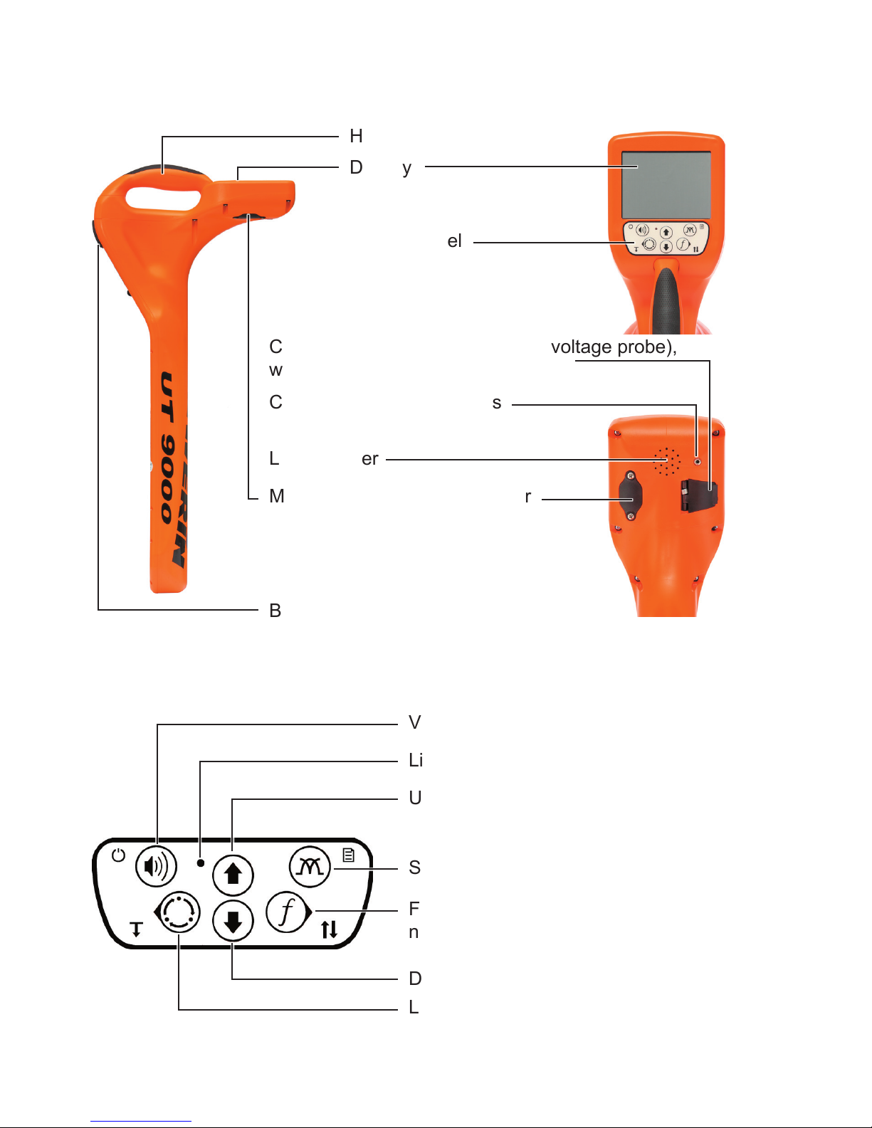
UT 9000 R receiver
Handle
Display
Control panel
Connection for accessories (step-voltage probe),
with cover
Connection for headphones
Battery compartment
Fig. 1: UT 9000 R receiver
Volume, ON/OFF, measuring mode
Light sensor
Frequency, direction recognition,
next, select
Location type, depth, back
Fig. 2: UT 9000 R receiver control panel (functions of the keys)
Loudspeaker
Mini USB connector, with cover
Up, gain up
Signal behaviour, menu
Down, gain down
Page 3
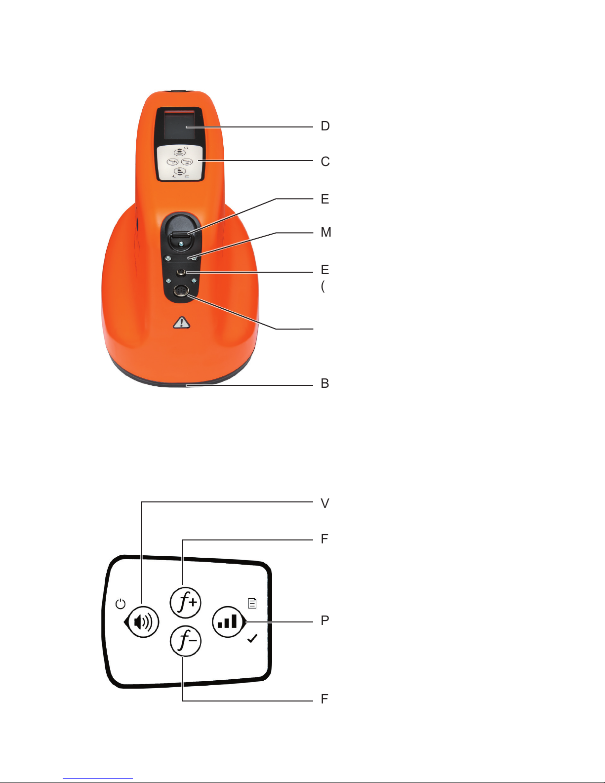
UT 9012 TX generator
Display
Control panel
Eye ring for carrying strap
Mini USB connector, with cover
External power supply connector
(vehicle cable)
Battery compartment
Fig. 3: UT 9012 TX generator
Volume, ON/OFF, back
Frequency up
Fig. 4: Generator control panel (functions of the keys)
Power level, menu, next, select
Frequency down
Connection for accessories
(set of cables, cable clamp)
Page 4

Information about this document
The warnings and notes in the document mean the following:
A
WARNING!
Risk of personal injury. Can result in serious injury or
death.
A
CAUTION!
Risk of personal injury. Can result in injury or a risk to
health.
NOTICE!
Risk of damage to property.
Note:
Tips and important information.
Enumerated lists (numbers, letters) are used for:
● Instructions that must be followed in a specic sequence
Bullet lists (bullet points, dashes) are used for:
● Lists
● Instructions comprising only one action
Page 5

I
Contents Page
1 Introduction .............................................................................1
1.1 Warranty ....................................................................................1
1.2 Purpose ..................................................................................... 2
1.3 Intended use .............................................................................3
1.4 General safety information ........................................................3
2 UT 9000 R receiver ..................................................................4
2.1 General .....................................................................................4
2.2 Location methods, location types and signal behaviour ............5
2.3 Control panel ............................................................................. 7
2.4 Display ......................................................................................9
2.5 Conguringthedevice(menu) ................................................13
2.5.1 Frequencies menu item ........................................................14
2.5.2 Settings menu item ..............................................................14
2.5.2.1 Language ..........................................................................15
2.5.2.2 Units .................................................................................. 15
2.5.2.3 Backlight............................................................................15
2.5.2.4 Shutdown Timer ................................................................15
2.5.2.5 Communications ...............................................................16
2.5.3 Options menu item ............................................................... 17
2.5.3.1 Audio Mode ....................................................................... 17
2.5.3.2 Audio Style ........................................................................ 18
2.5.3.3 Gain...................................................................................18
2.5.3.4 Autodepth .......................................................................... 18
2.5.3.5 Offset Depth ...................................................................... 18
2.5.4 System Info menu item ........................................................19
2.5.5 Ambient Noise menu item .................................................... 19
2.5.6 TX Control menu item ..........................................................19
2.6 Power supply ........................................................................... 20
3 UT 9005 TX / UT 9012 TX generator ..................................... 22
3.1 General ...................................................................................22
3.2 Operating modes ..................................................................... 22
3.3 Control panel ........................................................................... 23
3.4 Display ....................................................................................24
3.5 Conguringthedevice(menu) ................................................27
3.5.1 Frequencies menu item ........................................................28
3.5.2 Settings menu item ..............................................................28
3.5.2.1 Backlight............................................................................28
Page 6

II
Contents Page
3.5.2.2 Output ...............................................................................28
3.5.2.3 Meter ................................................................................. 30
3.5.2.4 Communications ...............................................................30
3.5.3 Options menu item ............................................................... 31
3.5.3.1 Language ..........................................................................31
3.5.3.2 Defaults ............................................................................. 32
3.5.3.3 Step-voltage probe ............................................................33
3.5.4 System info menu item .........................................................33
3.6 Power supply ........................................................................... 34
3.6.1 Changing the batteries ......................................................... 35
3.6.2 Lithium-ion rechargeable battery ..........................................36
3.6.2.1 Safety information regarding the lithium-ion rechargeable
battery ...............................................................................36
3.6.2.2 Storage of the rechargeable battery..................................36
3.6.2.3 Charging the battery..........................................................37
4 Using the UT 9000 system .................................................... 39
4.1 Device pairing .........................................................................39
4.1.1 Pairing the generator and the receiver ................................. 39
4.1.2 Disconnecting the generator and the receiver .....................40
4.2 Frequency selection ................................................................40
4.2.1 Enabling a frequency ...........................................................42
4.2.2 Selecting the frequencies ..................................................... 42
4.3 Gain control on the receiver ....................................................43
4.4 Depth measurement ................................................................ 44
4.4.1 Determining the depth automatically .................................... 44
4.4.2 Determining the depth manually ..........................................45
4.4.3 Determining the offset depth ................................................45
4.5 UT 9000 software ....................................................................47
5 Active location: lines ............................................................49
5.1 Determining the ambient noise ...............................................49
5.2 Energising a line ...................................................................... 51
5.2.1 Galvanic energising ..............................................................51
5.2.1.1 Parallel connection ............................................................52
5.2.1.2 Points to note when changing the set of cables ................54
5.2.2 Inductive energising .............................................................55
5.2.2.1 Energising with a cable clamp...........................................55
5.3 Locating a line .........................................................................56
5.4 Direction recognition ...............................................................58
Page 7

III
Contents Page
5.5 High Power .............................................................................. 60
6 Active location: sondes ........................................................ 62
7 Passive location ....................................................................65
8 Troubleshooting ....................................................................68
8.1 Sources of error when locating ...............................................68
8.2 Problems with the receiver ...................................................... 69
8.3 Problems with the generator ...................................................69
9 Appendix ................................................................................ 71
9.1 Technical data .........................................................................71
9.1.1 UT 9000 R receiver ..............................................................71
9.1.2 UT 9005 TX / UT 9012 TX generator ...................................72
9.2 Pre-set frequencies (factory settings) .....................................74
9.2.1 UT 9000 R receiver ..............................................................74
9.2.2 UT 9005 TX / UT 9012 TX generator ...................................75
9.3 Accessories and consumables ................................................ 76
9.4 EC Declaration of Conformity .................................................. 76
9.5 Advice on disposal ..................................................................77
10 Index ....................................................................................... 78
Page 8

1
1 Introduction
1 Introduction
1.1 Warranty
The following instructions must be complied with in order for any
warranty to be applicable regarding functionality and safe operation of this equipment. The product must only be operated by
qualiedspecialisttechnicians.
●
Read these operating instructions prior to operating the product.
● Use the product only as intended.
● Repairs and maintenance must only be carried out by special-
ist technicians or other suitably trained personnel. Only spare
parts approved by Hermann Sewerin GmbH may be used
when performing repairs.
● Use only suitable battery types.
● Changesormodicationstothisproductmayonlybecarried
out with the approval of Hermann Sewerin GmbH.
●
Use only Hermann Sewerin GmbH accessories for the product.
Hermann Sewerin GmbH shall not be liable for damages resulting
from the non-observance of this information. The warranty conditions of the General Terms and Conditions ("AGB") of Hermann
Sewerin GmbH are not affected by this information.
In addition to the warnings and other information in these Operating Instructions, always observe the generally applicable safety
and accident prevention regulations.
The manufacturer reserves the right to make technical changes.
Page 9

2
1 Introduction
1.2 Purpose
UT 9000 is an electronic location system for detecting electri-
cally conductive lines laid in the ground. The system comprises the UT 9000 R receiver and a generator (UT 9012 TX or
UT 9005 TX). Data is sent between the receiver and the generator via bidirectional radio.
The UT 9000 can be used for:
● Locating and tracking lines
Lines refers here to both power and signal cables as well as
supply lines, for example.
● Determining the depth of a line
Location can be carried out passively or actively. For active lo-
cation,therequiredelectromagneticeldisgeneratedbymeans
of a generator. Passive location makes use of existing electro-
magneticelds.
As with other systems, it is always advisable to check the plausibility of the result of the UT 9000 location process.
Note:
In these operating instructions, we describe the UT 9000 system
working in conjunction with a UT 9012 TX generator. The descriptions are also valid for the UT 9005 TX generator, however
it offers fewer functions.
All descriptions refer to the system as delivered (factory settings).
The manufacturer reserves the right to make changes.
Page 10

3
1 Introduction
1.3 Intended use
UT 9000 is intended for professional industrial and commercial
use. The appropriate specialist knowledge is required to operate
the device.
Note:
If necessary, learn more about pipe location theory before commencing practical work with the UT 9000.
Thesystemmustonlybeusedfortheapplicationsspeciedin
Section 1.2.
1.4 General safety information
● Contact the local utility companies to establish the route of un-
derground cables and lines before commencing location work.
●
Before starting work, check that the equipment is in good working order. Never use damaged or faulty equipment.
● Never use the equipment in the vicinity of explosive areas.
●
Always adequately secure the setup locations of the equipment to prevent injury to persons and damage to vehicles.
● Always observe the applicable safety regulations when work-
ing on electrical installations (e.g. power cables).
● Do not drop the devices.
●
Never place the devices in places where they are at risk of
falling.
● Ensure that no dirt or moisture can get into the connections
on the devices.
● Always observe the permitted operating and storage temper-
atures.
● Do not immerse the devices in liquids.
Page 11

4
2 UT 9000 R receiver
2 UT 9000 R receiver
2.1 General
The UT 9000 R receiver receives the signals from electromag-
neticelds.Thesignalsarerelayed:
● audibly via a loudspeaker or headphones
● visually on the display
Theeldstrengthisdisplayedingraphicalandnumericalformon
the display. The directional arrow and other graphical elements
help guide you towards the location object.
Youwill ndanoverview withthe namesofthe receiverparts
inside the front cover (Fig. 1).
The selected volume of the loudspeaker or headphones does
not affect the sensitivity of the device, i.e. loud signals are not
necessarily strong signals.
The UT 9000 R receiver can be used for both active and passive
location. Semi-automatic gain control can be used to simplify
active location.
The lower part of the receiver contains multiple antennas. The
selected signal behaviour determines exactly how they combine
within the device.
Page 12
5
2 UT 9000 R receiver
2.2 Location methods, location types and signal behaviour
Active and passive location with the UT 9000 are referred to location methods.
Two different location types are available for each of the location
methods. Different signal behaviours can be selected depending
on the location type. The location types and signal behaviour are
shown using symbols.
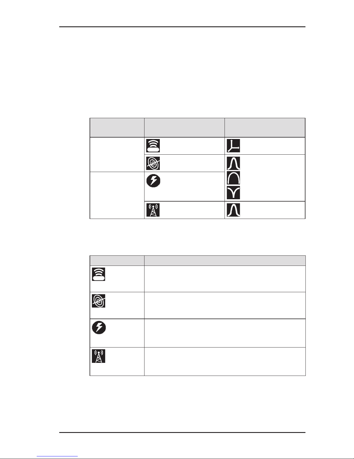
Location
mode
Location type Signal behaviour
active
location
sonde coordinates
line maximum narrow
maximum wide
minimum
passive
location
current
radio maximum narrow
Location types
Location type Suitable location objects
Sonde
● non-metal pipes carrying a sonde
Line
● lines being energised by a generator
(see section 3.2 on page 22)
Current
● current-carrying cables
– available frequencies: 50 Hz, 100 Hz,
150 Hz or 60 Hz, 120 Hz, 180 Hz
Radio
● metallic lines
– available frequency: radio, i.e. frequency
range 11.6 – 31.4 kHz (VLF range)
Page 13
6
2 UT 9000 R receiver
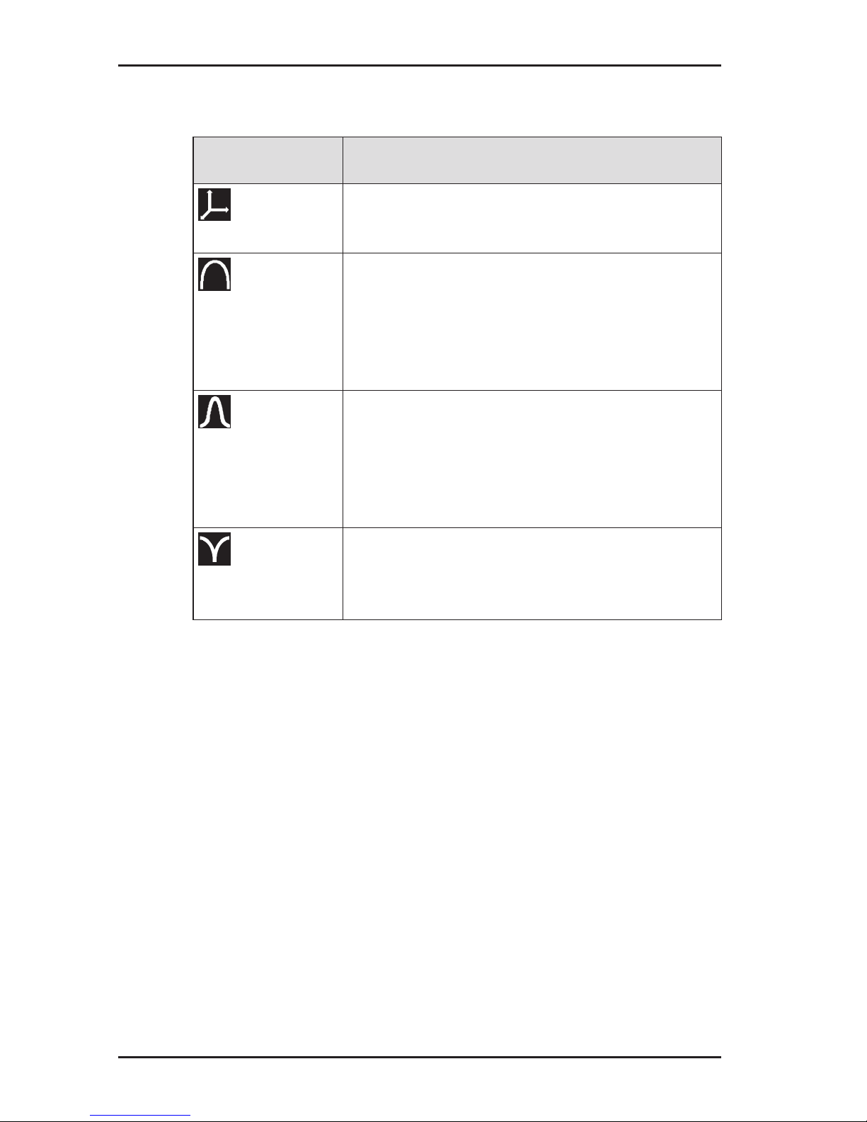
Signal behaviour
Signal
behaviour
Description
Coordinates
● for precise location of a sonde
● fordeterminingwherebre-opticcables
end
Maximum wide
● to determine the location of a line using
the maximum method
● in comparison to maximum narrow sig-
nal behaviour:
– wider range
– lower accuracy
Maximum
narrow
● to determine the location of a line using
the maximum method
● in comparison to maximum wide signal
behaviour:
– lower range
– greater accuracy
Minimum
● to determine the location of a line using
the minimum method (zero signal)
● signicantdistinctsignalcurveoverthe
line
Page 14

7
2 UT 9000 R receiver
2.3 Control panel
The control panel consists of six keys (Fig. 2 inside front cover).
Some keys have more than one function.
Key Function Action
Volume
● to increase the
volume or turn the
sound off
● presskeybriey
several times
ON/OFF
● to switch the de-
vice on
● press the key
● to switch the de-
vice off
● hold down the key
Measuring
mode
● to close the menu
and return directly
to the measuring
mode
● press the key
Location
type
● to select the loca-
tion type
● press the key
Depth
● in the case of
determining the
depth manually: to
enable the depth
measurement
● press the key until
an acoustic signal
sounds
Back
● in a menu: to re-
turn to the next
level up
● press the key
briey
Up
● in a menu: to se-
lect or to move up
● press the key
Gain up ● to increase the
gain
● press the key
(semi-automatic
gain control adjustment)
● press the key re-
peatedly (manual
gain control adjustment)
Page 15
8
2 UT 9000 R receiver
Key Function Action
Down
● in a menu: to se-
lect or to move
down
● press the key
Gain down ● to reduce the gain ● press the key
(semi-automatic
gain control adjustment)
● press the key re-
peatedly (manual
gain control adjustment)
Signal
behaviour
● to select the sig-
nal behaviour
● press the key
briey
Menu
● to open a menu ● hold down the key
Frequency
● to select a fre-
quency
● presskeybriey
several times
Direction
recognition
● to enable direction
recognition
● press the key until
an acoustic signal
sounds
Next
● in a menu: to go
to the next level
down
● press the key
Select ● to select a setting
(enable/disable)
● press the key
Page 16
9
2 UT 9000 R receiver
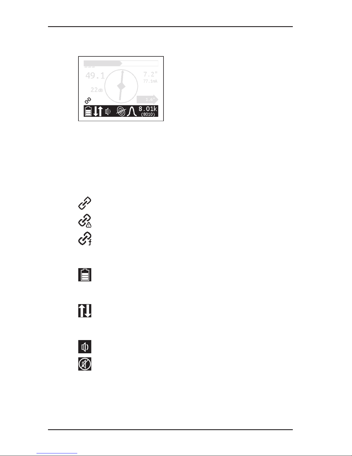
2.4 Display
Fig. 5: UT 9000 R receiver display (overview)
Theupperareadisplaystheeldstrengthandgainingraphical
form. The lower area consists of a tool bar which displays the
current settings and conditions using symbols.
The central area is used to help guide you towards the location
object with the help of graphical elements. The current measurement values are displayed on the right and left-hand sides.
Field strength
Fig. 6: Receiverdisplay–eldstrengthdisplay
Theeldstrengthisdisplayed:
● numerically
in the example (Fig. 6): 49.1
● graphically
thelargerthebar,thegreatertheeldstrength.
Page 17
10
2 UT 9000 R receiver
Gain
Fig. 7: Receiver display – gain display
Theeldstrengthisdisplayed:
● numerically
in the example (Fig. 7): 22 dB
● graphically
The more segments that are visible, the higher the gain.
Depth
Fig. 8: Receiver display – depth and distance display
The depth is displayed numerically. The unit of measurement
can be set.
in the example (Fig. 8): 7.2"
If offset depth determination is enabled, the distance to the location object is also displayed inside a black arrow.
in the example (Fig. 8): 1.6"
In addition, the current is also shown on the display. This helps for
example in identifying the energised line in case of parallel lines.
in the example (Fig. 8): 77.1 mA
Page 18
11
2 UT 9000 R receiver
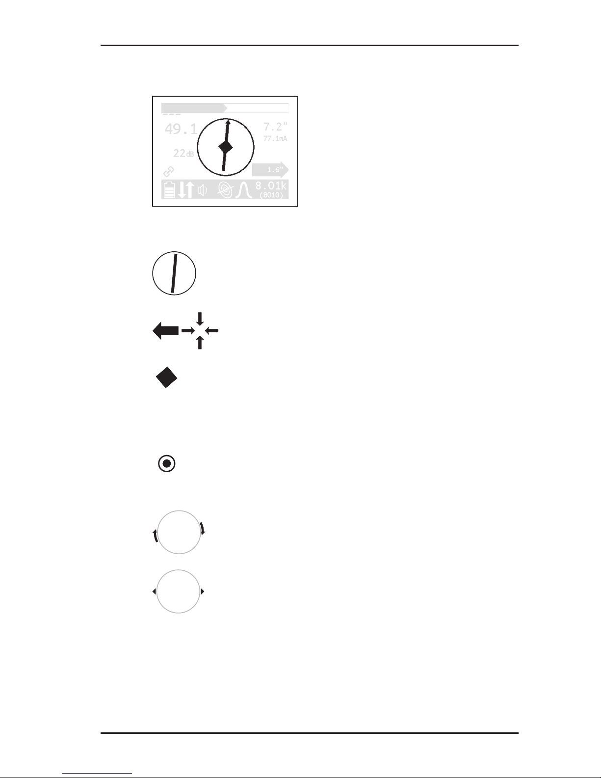
Graphical elements
Fig. 9: Receiver display – graphical elements
Compass with needle
● the compass needles show the position of the
line.
Directional arrows
● the receiver needs to be moved in the direction
of the arrow shown.
Diamond
● the receiver is located directly above the loca-
tion object.
When locating sondes:
Point
● the receiver is located above a minimum in the
signal curve.
Turn arrows
● the receiver needs to be turned in the direction
of the arrow shown.
Tips
● the tips show the position of the sonde.
Page 19
12
2 UT 9000 R receiver
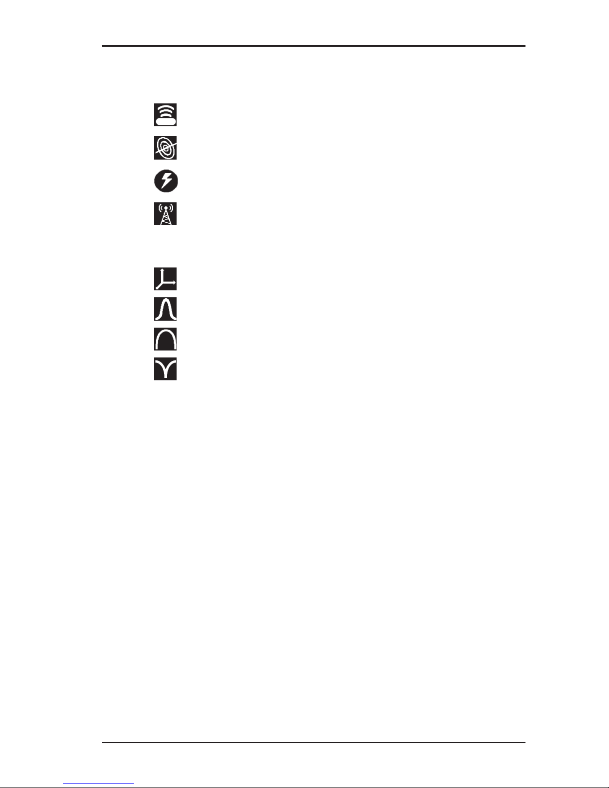
Symbols
Fig. 10: Receiver display – symbols
The selected frequency is displayed twice on the right-hand side
of the tool bar. For frequencies over 1,000 Hz, the top value is
displayed in kHz and underneath in Hz.
Information about the generator
receiver and generator paired
generator beyond radio range
selected frequency not enabled in generator
Battery status
remaining battery capacity
Miscellaneous
direction recognition enabled
Volume
tone switched on
tone switched off
Page 20
13
2 UT 9000 R receiver
Location type
sonde
line
current
radio
Signal behaviour
coordinates
maximum narrow
maximum wide
minimum
2.5 Conguring the device (menu)
The menu can be used for making settings and for retrieving information about the device. The following menu items are available:
● Frequencies
● Settings
● Options
● System Info
● Ambient noise
● TX Control
Opening the menu
With the device switched on:
● Hold down the menu key. The menu appears.
Page 21

14
2 UT 9000 R receiver
Opening a menu item
With the menu open:
1. Press the up or down key. The selected menu item will be
highlighted.
2. Press the next key. The selected menu item is opened.
Changing the settings
With the menu item for which you wish to change the settings:
1.
Press the up or down key. The selected setting is highlighted.
2. Press the next key. The setting will be enabled/disabled.
3. Press the back key. The setting will be accepted. The device
will be returned to the next level up.
Exiting the menu or a menu item
With the menu or a menu item open:
●
Press the back key. The device will be returned to the next
level up.
Returning directly to the measuring mode
With the menu or a menu item open:
●
Press the volume key. The device will return directly to the
measuring mode.
2.5.1 Frequencies menu item
The Frequencies menu item is used to enable or disable the
pre-set frequencies. Symbols indicate which individual frequencies are suitable for the different location types.An explanation
of these symbols can be found in section 9.2.1 on page 74.
For more detailed information on which frequencies to select,
please refer to section 4.2 on page 41.
Page 22

15
2 UT 9000 R receiver
2.5.2 Settings menu item
The Settings menu item can be used to modify the following
settings:
● Language
● Units
● Backlight
● Shutdown Timer (shutdown time)
● Communications
2.5.2.1 Language
The Language menu item is used to change the language used
on the display.
2.5.2.2 Units
The Units menu item is used to modify the units of measurement
for the distance (depth) and offset depth.
2.5.2.3 Backlight
The Backlight menu item is used to switch the display backlight
on and off.
If the backlight is enabled (Autom./automatic), the display is lit
up in the case of low levels of light. The sensor for this automatic
control can be found on the control panel.
2.5.2.4 Shutdown Timer
The Shutdown Timer menu item is used to set the time after
which the device should be shut down if not in use.
If Always On is selected, the device never shuts down auto
-
matically.
Page 23

16
2 UT 9000 R receiver
2.5.2.5 Communications
The following options are available in the Communications
menu item:
● Radio On/Off
● Bluetooth
● Link Info (linking information)
● Link TX
● Unlink TX
Radio On/Off
The Radio On/Off menu item can be used to disconnect or re-
establish the radio connection between the generator and the
receiver.
An example of when it may be necessary to disconnect the radio
connection is when attempting to make a secure connection to a
Bluetooth device (e.g. GPS mouse).
Note:
Disconnecting the radio connection does not cut an existing pairing of generator and receiver.
Bluetooth
The Bluetooth menu item is used for saving location results on
an external Bluetooth device (e.g. GPS mouse), making it possible to document location results.
The receiver needs to be connected to the Bluetooth device in
order for data transmission to be possible. Once the data has
been transmitted, the devices are disconnected again.
Page 24

17
2 UT 9000 R receiver
Pairing information
The Link Info menu item is used to display information on pairing
with a generator.
If a receiver is paired with a generator, the device number of the
generator is displayed in Linked To.
Link TX
The menu item Link TX is used to pair a receiver with a generator.
For more detailed information on pairing, please refer to section 4.1.1 on page 39.
Unlink TX
The menu item Unlink TX is used to unpair an existing link between a receiver and a generator.
For more detailed information on unpairing, please refer to section 4.1.1 on page 39.
2.5.3 Options menu item
The Options menu item can be used to modify the following:
● Audio Mode
● Audio Style
● Gain
● Autodepth
● Offset Depth
2.5.3.1 Audio Mode
The Audio Mode menu item can be used to set the acoustic
signal type.
● Pitch
The pitch of the signal changes (up/down).
● Volume
The volume of the signal changes (loud/quiet).
Page 25

18
2 UT 9000 R receiver
2.5.3.2 Audio Style
The Audio Style menu item is used for setting which kind of
sound reproduction is used.
● Classic
● Smooth
2.5.3.3 Gain
The Gain menu item is used to set how the gain on the received
signals is readjusted. The gain control must always be readjusted
by the user.
● Manual
Incremental gain control adjustment up to desired gain.
● Semi-auto (semi-automatic)
Gain control adjustment is carried out within the optional gain
range.
More information about adjusting the gain can be found in section 4.3 on page 43.
2.5.3.4 Autodepth
The Autodepth menu item is used to set how the depth of the
location object should be determined.
● Autodepth (automatically)
The depth is displayed automatically as soon as the device is
located directly above the location object.
● Manual
The user need to press the depth key for the depth to be determined.
2.5.3.5 Offset Depth
The Offset Depth menu item can be used to enable or disable
the determination of the offset depth.
For more detailed information on the offset depth, please refer to
section 4.4.3 on page 45.
Page 26

19
2 UT 9000 R receiver
2.5.4 System Info menu item
The System Info menu item displays information about the device. This information may be spread across several pages.
● Press the down key to display all the information.
2.5.5 Ambient Noise menu item
The Ambient Noise menu item can be used to determine which
of the enabled frequencies are present and at what strength in
the surrounding areas for each location type.
For more detailed information on ambient noise, please refer to
section 5.1 on page 49.
2.5.6 TX Control menu item
Note:
The TX Control menu item is only available when the receiver
is paired with a generator.
With the help of the TX Control menu item, the receiver is able
to control the generator in measuring mode. The generator must
be switched on.
Thefollowing settingscanbe modiedfor thecurrent location
situation:
● Power level
● Dual Output, as long as a Y-cable (double set of cables) is
attached to the generator.
Thischangestheassignation oftheowof currentbetween
the red and white cables. The cable not in use is shown as
crossed out.
Information on dual output can be found in section 3.5.2.2 on
page 28.
Page 27

20
2 UT 9000 R receiver
Controlling the generator via the receiver
On the receiver:
1. In the menu, select: Settings > TX Control.
The operating mode display appears. The symbol of the func-
tionwhichcanbemodiedashes.
− Press the down or up key to change between power level
and dual output.
−
Click on the next key to change the corresponding settings.
2. Click on the back key to accept the changes.
2.6 Power supply
The device can be operated with either disposable or regular
rechargeable batteries.
NOTICE! Risk of damage due to leaking batteries
● Never mix power sources of different types (disposable or re-
chargeable), capacity, condition (new or used) or manufacturer.
Page 28

21
2 UT 9000 R receiver
Changing the batteries
The battery compartment cover is locked with a quick-release
fastener.
1. Turn the quick-release fastener to open the battery compartment.
2. Remove the used batteries.
3. Insert new batteries. Ensure correct polarity (Fig. 11).
Fig. 11: Changing the batteries in the receiver – battery polarity
4. Close the battery compartment.
5.
Check that the device is ready for operation by switching it on.
If the battery polarity is incorrect, the device will not switch on.
Page 29

22
3 UT 9005 TX / UT 9012 TX generator
3 UT 9005 TX / UT 9012 TX generator
3.1 General
The generator can be used to energise lines both galvanically
and inductively. The generator is, therefore, often also referred
to as a transmitter.
Different frequencies are available for energising lines. The most
common frequencies are pre-set as default settings (see section 9.2.2 on page 75).
Youwillndanoverviewwiththenamesofthegeneratorparts
inside the front cover (Fig. 3).
When the sound is switched on, a continuous signal sounds. This
signal is used to ensure the working area is safe.
The generator is available in two different models:
● UT 9012 TX
− 12 watt output
● UT 9005 TX
− 5 watt output
− no external power source connector
3.2 Operating modes
The device can be used to energise lines galvanically and inductively. The selected operating mode is indicated by means
of symbols.
Operating mode Energising with
inductive
energising
cable clamp
generator without accessories
(using internal frame coil)
galvanic
energising
set of cables (single set of cables)
Y-cable (double set of cables)
Page 30

23
3 UT 9005 TX / UT 9012 TX generator
3.3 Control panel
The control panel consists of four keys (Fig. 4 inside front cover).
Some keys have more than one function.
Key Function Action
Volume
● to turn the tone on
● to turn the tone off
● press the key
briey
ON/OFF
● to switch the de-
vice on
● press the key
● to switch the de-
vice off
● hold down the key
Back
● in a menu: to re-
turn to the next
level up
● press the key
briey
Power Level
● to select the pow-
er level
● presskeybriey
several times
Menu
● to open a menu ● hold down the key
Next
● in a menu: to go
to the next level
down
● press the key
briey
Select
● to select a setting
(enable/disable)
● press the key
briey
Frequency
up
● to increase the
frequency
● press the key
briey
Frequency
down
● to reduce the
frequency
● press the key
briey
Page 31

24
3 UT 9005 TX / UT 9012 TX generator
3.4 Display
Fig. 12: UT 9012 TX generator display (overview)
The left-hand side of the display uses symbols to show the current settings and statuses. The right-hand side of the display
shows the frequency and different parameters as numerical values.
Symbols
Fig. 13: Generator display – symbols
Battery status
remaining capacity of the battery or lithium-ion rechargeable battery
Connections
USB connected
external power supply
Page 32

25
3 UT 9005 TX / UT 9012 TX generator
Power
selected power level
high power enabled
Volume
tone switched on
tone switched off
Generator status
generator transmitting
generator not transmitting
generator unable to transmit (connection error during
galvanic energising)
Miscellaneous
direction recognition enabled
generator paired with receiver
step-voltage probe enabled
Energising with
cable clamp connected
generator without accessories (using internal frame coil)
set of cables (single set of cables) connected
Y-cable (double set of cables) connected
Page 33

26
3 UT 9005 TX / UT 9012 TX generator
Frequency
Fig. 14: Generator display – frequency display
The selected frequency is displayed twice. For frequencies over
1,000 Hz, the top value is displayed in kHz and underneath in Hz.
Parameters
Fig. 15: Generator display – parameters
The parameters show the current generator values when energising. The values shown depend on:
● operating mode
● the settings in Meter
More information about the settings for meter can be found in
section 3.5.2.3 on page 30.
Page 34

27
3 UT 9005 TX / UT 9012 TX generator
3.5 Conguring the device (menu)
The menu can be used for making settings and for retrieving information about the device. The following menu items are available:
● Frequencies
● Settings
● Options
● System Info
Opening the menu
With the device switched on:
● Hold down the menu key. The menu appears.
Opening a menu item
With the menu open:
1. Press the frequency up or frequency down key. The selected menu item will be highlighted.
2. Press the next key. The selected menu item is opened.
Changing the settings
With the menu item for which you wish to change the settings:
1. Press the frequency up or frequency down key. The selected setting is highlighted.
2. Press the select key. The setting will be enabled/disabled.
3. Press the back key. The setting will be accepted. The device
will be returned to the next level up.
Exiting the menu or a menu item
With the menu or a menu item open:
●
Press the back key. The device will be returned to the next
level up.
Page 35

28
3 UT 9005 TX / UT 9012 TX generator
3.5.1 Frequencies menu item
The frequencies menu item is used to enable or disable the pre-
set frequencies. Symbols indicate which individual frequencies
are suitable for the different operating modes.
An explanation of these symbols can be found in section 9.2.1
on page 74.
For more detailed information on which frequencies to select,
please refer to section 4.2 on page 41.
3.5.2 Settings menu item
The settings menu item can be used to modify the following
settings:
● Backlight
● Output
● Meter
● Communications
3.5.2.1 Backlight
The Backlight menu item is used to switch the display backlight
on and off.
If the backlight is enabled (ON), an additional menu item appears:
Timer. This menu item can be used to set the time after which the
backlight is automatically switched off if the device is temporarily
not in use. Default: 5 seconds.
3.5.2.2 Output
Note:
The Output menu item is only available when a set of cables is
connected to the generator. The set of cables must be connected
before opening the menu.
Page 36

29
3 UT 9005 TX / UT 9012 TX generator
The Output menu item can be used to set special functions for
the output signal. The following menu items are available:
● Direction Enabled (direction recognition)
● High Power
● Dual Output (Y-cable)
Direction Enabled
The Direction Enabled menu item is used to enable direction
recognition.
For more detailed information on direction recognition, please
refer to section 5.4 on page 58.
High Power
The High Power menu item is used to set the generator to ener-
gisewithanoutputpowerof12Wforaspeciedtime.
When the High Power function is enabled, a Timer can be set
to specify how long the generator should be energised at 12 W.
Default: 5 minutes.
For more detailed information on this function, please refer to
section 5.5 on page 60.
Dual Output
When working with a parallel connection, we need to specify
which of the cables in a Y-cable (double set of cables) is primarily
enabled and which is blocked during energising. This pre-allocation can be set in the Dual Output menu item.
For more detailed information on parallel connections and preallocation, please refer to section 5.2.1.1 on page 53.
Page 37

30
3 UT 9005 TX / UT 9012 TX generator
3.5.2.3 Meter
The Meter menu item is used to specify which values are shown
on the display in the parameter area (Fig. 15).
Operating mode Meter
Simple Advanced
inductive energising
with
cable
clamp
● current [mA] ● current [mA]
● voltage [V]
generator
without
accessories
● power percentage
based on output
power [%]
● power percentage
based on output
power [%]
● voltage [V]
galvanic energising
● current [mA] ● current [mA]
● power output [W]
● resistance[Ω]
● voltage [V]
3.5.2.4 Communications
The following options are available in the Communications
menu item:
● Radio On/Off
● Link RX
● Un-Link RX
● Link Information (pairing information)
Radio On/Off
The Radio On/Off menu item can be used to disconnect or re-
establish the radio connection between the generator and the
receiver.
An example of when it may be necessary to disconnect the radio
connection is when attempting to make a secure connection to a
Bluetooth device (e.g. GPS mouse).
Page 38

31
3 UT 9005 TX / UT 9012 TX generator
Note:
Disconnecting the radio connection does not cut an existing pairing of generator and receiver.
Link RX
While the receiver and generator are paired, information on the
status of the connection is displayed in the Link RX menu item.
For more detailed information on pairing, please refer to section 4.1.1 on page 39.
Un-Link RX
The menu item Un-Link RX is used to unpair an existing link
between a generator and a receiver.
For more detailed information on unpairing, please refer to section 4.1.1 on page 39.
Pairing information
The Link Information menu item is used to display information
on pairing with a receiver.
If a generator is paired with a receiver, the device number of the
receiver is displayed in RX Name.
3.5.3 Options menu item
The Options menu item can be used to modify the following:
● Language
● Defaults
● Fault Mode (step-voltage probe)
3.5.3.1 Language
The language menu item is used to change the language used
on the display.
Page 39

32
3 UT 9005 TX / UT 9012 TX generator
3.5.3.2 Defaults
Use the Defaults menu item to return the following settings to
factory defaults:
● Settings (backlight, output, meter, communications)
● Options (language, fault mode)
Note:
The default language setting for the device is English: be aware
that all text on the display will appear in English after returning
to factory settings.
Resetting the defaults
1. Open the Defaults menu item. A warning prompt will appear.
2. If you really wish to reset the default values, press the fre-
quency up key. The OK eldishighlighted.
3. Press the select key. The settings are now returned to their
defaults.
Page 40

33
3 UT 9005 TX / UT 9012 TX generator
3.5.3.3 Step-voltage probe
Note:
The Fault Mode menu item is only available when a set of cables
is connected to the generator. The set of cables must be connected before opening the menu.
The Fault Mode menu item is used to enable or disable a
step-voltage probe.
Step-voltage probes are used to measure cable faults. FF (Fault
Finder) will appear on the display instead of the frequency when
a step-voltage probe is enabled.
The step-voltage probe can be purchased additionally as an accessory.
3.5.4 System info menu item
The System Info menu item displays information about the device. This information may be spread across several pages.
● Press the frequency down key to display all the information.
Page 41

34
3 UT 9005 TX / UT 9012 TX generator
3.6 Power supply
Both internal and external power supplies can be used to provide
power.
Internal power supply
The device can be operated with either disposable or rechargeable lithium-ion batteries.
Different battery compartment covers (Fig. 16) are required depending on which kind of battery is used.
Power source Battery compartment feature
Disposable batteries Battery holder for ten batteries inside
the battery compartment
Lithium-ion
rechargeable battery
Rechargeable battery integrated into
battery compartment
The battery compartment covers have a sticker on the outside
whichspeciesthepowersupply.
Fig. 16: A generator with the battery compartment open (upper image).
Both battery compartment covers with disposable batteries (bottom left) or with an integrated rechargeable lithium-ion battery
(bottom right) can be used.
Page 42

35
3 UT 9005 TX / UT 9012 TX generator
External power supply
The external power supply is connected via a vehicle cable.
Whenever a power source (e.g. external rechargeable battery)
is connected to the external power supply, the internal power
supply is cut off.
3.6.1 Changing the batteries
Ten disposable D/LR20 alkaline batteries are required to power
the device.
NOTICE! Risk of damage due to leaking batteries
● Never mix power sources of different types (disposable or re-
chargeable), capacity, condition (new or used) or manufacturer.
The battery compartment cover is locked with quick-release fasteners.
1.
Turn the quick-release fasteners to open the battery compartment.
2. Remove the used batteries.
3. Insert new batteries. Ensure correct polarity (Fig. 17).
Fig. 17: Changing the batteries in the generator – battery polarity
4. Close the battery compartment.
5.
Check that the device is ready for operation by switching it on.
If the battery polarity is incorrect, the device will not switch on.
Page 43

36
3 UT 9005 TX / UT 9012 TX generator
3.6.2 Lithium-ion rechargeable battery
A special lithium-ion rechargeable battery is required to power
the device.
The lithium-ion rechargeable battery can be purchased additionally as an accessory.
3.6.2.1 Safety information regarding the lithium-ion rechargeable
battery
●
Danger of short-circuit! Do not touch the power connector
poles with metallic objects.
● Never attempt to open the rechargeable battery.
● Never use a damaged rechargeable battery.
● Prevent humidity from entering the rechargeable battery.
● Ensure the correct conditions when charging, storing and op-
erating the battery.
Ensure special protection against very high or low temperatures.
● Protect the battery from mechanical stress (knocks, vibration).
Never drop the battery.
● Neverdisposeofthebatteryinare.
● Always dispose of rechargeable batteries in accordance with
local regulations.
3.6.2.2 Storage of the rechargeable battery
If the rechargeable battery is to be stored for a long period of
time, certain preventive and care measures need to be taken
during storage.
Storage conditions
ideal ● temperature < 21 °C
● dry environment
● ambient air free of corrosive gases
permissible ● temperature -20 °C to 50 °C
● relative humidity < 80 %
Page 44

37
3 UT 9005 TX / UT 9012 TX generator
Note:
The device can be stored temporarily up to a temperature of
50°C, however prolonged exposure to temperatures above 45 °C
will reduce the battery's performance and life.
NOTICE! Danger of battery destruction
Rechargeable batteries which have completely lost their charge
cannot be recharged.
● Before storage, charge or discharge the rechargeable battery
to around 30 – 50 % capacity.
● Always store the battery in optimum storage conditions.
● Recharge the battery every 6 months in order to ensure it nev-
er self-discharges entirely. Only ever charge the rechargeable
battery to around 30 – 50 % capacity.
3.6.2.3 Charging the battery
The rechargeable battery is integrated into battery compartment
cover. There is a charging socket on the long side of the battery
compartment cover.
NOTICE! Danger of battery destruction
The rechargeable battery has a dedicated adapter.
● Only use the UT 9000 AC/DC adapter to charge the battery.
● Before using the AC/DC adapter to charge the battery, ensure
it is in perfect condition. Never use a damaged AC/DC adapter.
● Always observe the permitted charging conditions: tempera-
ture 0 °C – 45 °C, relative humidity < 80 %.
The battery compartment cover is locked with quick-release fasteners.
1.
Turn the quick-release fasteners to open the battery compartment. Remove the battery compartment cover with the
integrated rechargeable battery.
Page 45

38
3 UT 9005 TX / UT 9012 TX generator
2. Connect the rechargeable battery to a suitable power source
using the AC/DC adapter.
The battery will be charged. The LED on the AC/DC adapter
will display the current charging status:
LED State of charge
red battery charging
green battery fully charged (charging process completed)
Note:
The LED will still be green when the power supply
is connected to the mains, even if the rechargeable battery is not connected to the charging unit.
3. Once the battery is fully charged, remove it from the power
supply.
4. Replace the battery compartment cover into the battery compartment. Close the battery compartment.
Page 46

39
4 Using the UT 9000 system
4 Using the UT 9000 system
4.1 Device pairing
For active location, a receiver needs to be assigned to a generator so that the two form a device pair. To do so, the receiver
and generator are linked. The device number is the means of
identication.
Existing device pairings can be removed and the devices can
then be paired once again or different devices can be paired.
4.1.1 Pairing the generator and the receiver
During the pairing process, a generator is assigned to a receiver.
Only paired devices can communicate via radio.
Note:
the connection between the receiver and the generator can only
be established from the receiver.
1. On the generator:
− In the menu, select:
Settings > Communications > Link RX.
2. On the receiver:
a) In the menu, select:
Settings > Communications > Link TX.
b) Wait until the initialisation process is complete.
c)
Press the next key. The search for suitable devices begins.
A message appears with how many suitable devices have
been found in the area. The compatible devices are then
shown alongside their device numbers.
d) Select the desired device.
e) Press the next key. The pairing is established.
Once the receiver and generator have been paired successfully, a message appears.
Page 47

40
4 Using the UT 9000 system
Once the receiver and generator are paired, the measuring mode
display on each device shows the paired symbol.
4.1.2 Disconnecting the generator and the receiver
In order to disconnect an existing device pairing, each device
must be disconnected separately.
1. On the generator:
a) In the menu, select:
Settings > Communications > Unlink RX. A prompt will
appear.
Note:
The prompt will even appear if there is no pairing between the
generator and receiver.
b)
Press the frequency up key if you really want to disconnect
the devices. The OK eldishighlighted.
c) Press the select key. The pairing is disconnected.
The paired symbol no longer appears on the display in
measuring mode.
d) Switch the generator off and then back on again.
2. On the receiver:
a) In the menu, select:
Settings > Communications > Unlink TX. A prompt will
appear.
b)
Press the down key if you really want to disconnect the
devices. The Unlink eldishighlighted.
c) Press the next key. The pairing is disconnected.
The paired symbol no longer appears on the display in
measuring mode.
d) Switch the receiver off and then back on again.
Page 48

41
4 Using the UT 9000 system
4.2 Frequency selection
Frequencies can be available, pre-set and enabled. Only enabled
frequencies can be used for location.
● Available frequencies
75 different frequencies are available in the system.
An overview of the available frequencies can be found in the
appendix (section 9.2 on page 74).
● Pre-set frequencies
The pre-set frequencies are a selection of all of the available
frequencies.
All pre-set frequencies can be found on the devices in the
menu under Frequencies.
The most common frequencies are pre-set as default settings.
If other, additional frequencies are required, they must be set
up on the system using the UT 9000 software.
● Enabled frequencies
Enabled frequencies are a selection of all of the pre-set frequencies.
Only enabled frequencies can be used for location. Frequencies which are not required can be disabled.
Page 49

42
4 Using the UT 9000 system
4.2.1 Enabling a frequency
Note:
SEWERIN recommends enabling any eligible frequencies before
starting the location process in order to successfully determine
the ambient noise.
The required frequencies must be enabled on both the generator
and the receiver.
1. On the generator:
a) In the menu, select: Frequencies
b)
Enable the required frequencies. Where applicable, disable
any unrequired frequencies.
Pay attention to the suitability of the different frequencies
for certain operating modes.
2. On the receiver:
a) In the menu, select: Frequencies
b)
Enable the required frequencies. Where applicable, disable
any unrequired frequencies.
Pay attention to the suitability of the different frequencies
for certain location types.
4.2.2 Selecting the frequencies
Optimum results are only possible when the correct frequency
is set.
In the case of the location type Sonde, the frequency on the receiver must correspond with the frequency of the location object.
Thefrequency canbemodied duringthe locationprocess in
the following location types until the optimum frequency is found:
● line (active location)
● current (passive location)
All enabled frequencies will be available for selection.
Page 50

43
4 Using the UT 9000 system
Note:
SEWERIN recommends beginning the location process with a
suitable frequency.
● Always determine the ambient noise before starting (see sec-
tion 5.1 on page 49).
Thefrequencycanbemodiedoneitherthereceiverorthegenerator. NB:
●
If the frequency is changed on the receiver, it will automatically
bemodiedonthepairedgenerator.
● If the frequency is changed on the generator, however, it must
bemodiedmanuallyonthereceiver.
The following keys are used to change the frequency:
● On the receiver: frequency
● On the generator: frequency up or frequency down
4.3 Gain control on the receiver
During the location process, the signal reception can be inadequate or excessive. This effect can be counterbalanced by adjusting the gain.
In the case of gain:
● high gain > high signal sensitivity: location can be carried out
further away from the generator
● low gain > low signal sensitivity: may reduce excessive signal
strength
The gain can be controlled either manually or semi-automatically
according to the settings (see section 2.5.3.3 on page 18).
Page 51

44
4 Using the UT 9000 system
Manual adjustment of gain
●
Press the gain up key several times or hold it down to increase
the gain.
● Press the gain down key several times or hold it down to re-
duce the gain.
Semi-automatic adjustment of gain
The gain is optimised automatically when you press the key.
● Press the gain up key once if the gain is too low.
● Press the gain down key once if the gain is too high.
4.4 Depth measurement
Thedepthspecies thedistancefrom thebottom edgeofthe
receiver and the middle of the line. When locating sondes, the
depth shown refers to the middle of the sonde.
Note:
Please note before any excavation that the depth always refers
tothecentreoftheelectromagneticeld.Thetopedgeoflarge
lines,therefore,maynotbeasdeepasspecied.
Units
The depth can be displayed in various units.
The unit of measurement can be set in the menu under Settings >
Units.
Depth measurement type
The depth can either be determined automatically or manually.
The type of depth measurement can be set in the menu under
Options > Autodepth.
Page 52

45
4 Using the UT 9000 system
4.4.1 Determining the depth automatically
If automatic depth measurement is set, the depth is displayed as
soon as the receiver is located above the location object.
If the receiver is not located above the location object, no value
is displayed for the depth.
Note:
In the case of very uneven surfaces, it is not always possible for
the device to determine the depth, however in such cases it is
always possible to determine the depth manually.
4.4.2 Determining the depth manually
If manual depth measurement is set, the depth key needs to be
pressed until the unit emits a beep.
4.4.3 Determining the offset depth
In addition to simple depth measurement, the so-called offset
depth can also be calculated. In this case, the device also determines the distance to the location object as well as its depth.
This function is useful if
●
obstacles above the line in question prevent a direct depth
measurement
●
the plausibility of results for a simple depth measurement
should be checked
The offset depth is determined by triangulation. The display
shows the following:
● the distance X from the receiver to the location object
● the depth D of the location object
Page 53

46
4 Using the UT 9000 system
Fig. 18: Determining the offset depth
D depth
X distance receiver – location object
T tilt angle of the receiver
The settings in Options > Autodepth are used to specify wheth-
er the offset depth is displayed automatically or determined manually.
1. Enable the Offset Depth function.
To do so, select the following in the menu: Options > Offset
Depth > On.
2. Locate a line.
3.
Hold the receiver as parallel as possible to the assumed route
of the line.
4. Tilt the receiver to an angle T of between 10° – 60° (Fig. 18).
5. Once directional arrows appear on the screen:
−
move the receiver according to the directional arrows
shown.
− while doing so, vary the tilt angle of the receiver.
The directional arrows change into a diamond once the receiver is in an optimum position.
6. The values for the depth and distance are now shown
− automatically if automatic depth measurement is set
−
upon pressing the depth key if manual depth measurement
is set
Page 54

47
4 Using the UT 9000 system
4.5 UT 9000 software
The UT 9000 softwareisusedtoupdateandconguredevices
inanefcientmanner.Individualsettingscanbestoredinale
for future use.
Requirements:
● the software must be installed on a computer
● the device (receiver or generator) must be connected to the
computer via a USB cable
The software is used to carry out the following tasks:
● updatingthermware
● pre-setting the frequencies
● enabling the frequencies
● conguringthedevice(accordingtomenuitemsSettings and
Options)
● setting up the start screen (e.g. adding a company logo)
The software can be downloaded free of charge from www.
sewerin.com(Products>Downloads>Software).Anotication
is displayed if there is an update available for the software.
Updating or conguring the device via the software
1. Remove the cover to the USB connection on the device.
2. Connect the device to the computer using a USB cable.
3. Launch the software.
4. Click on Connect on the Software Update tab. The device
should now be recognised by the software.
5. Perform the required tasks in the software.
6. Disconnect the device from the computer.
7. Ensure that the USB cover on the device is closed properly
to make sure that no humidity can enter.
Page 55

48
4 Using the UT 9000 system
NOTICE! Possibility of destroying thread when replacing
screws
The cover to the USB connection is adapted to the contour of the
UT 9000 R receiver.
● Ensure that the cover is replaced correctly.
8. Ifnecessary,updateorcongureotherdevices.
9. Close the software.
Page 56

49
5 Active location: lines
5 Active location: lines
In active location, a generator is used to produce an electromag-
neticeldaroundthelinetobelocated.Theenergisedlinecan
then be located.
Carry out the following steps to locate a line using active location:
1. determine the ambient noise
2. energise the line
3. locate the line
5.1 Determining the ambient noise
Lines are often surrounded by frequencies which can make loca-
tionmoredifcult(interferencesignals).Theambientnoiseneeds
to be determined in order to be able to select a suitable frequency
for energising and locating the line despite these interferences.
The process consists of the receiver testing which enabled frequencies are found in the surroundings and at what strength.
Ambient noise can only be determined in the following location
types:
● line (active location)
● current (passive location)
Suitability of a frequency for location
Location
mode
Location
type
Signal strength (interference signal)
high low
active line
unsuitable
frequency
suitable frequency
passive current
suitable frequency unsuitable
frequency
Page 57

50
5 Active location: lines
Note:
The decision on which of the suitable frequencies is actually used
for subsequent energising and locating assumes corresponding
expert knowledge.
1. Ensure that the generator is switched off.
2. On the receiver:
a) Select the location type: Line.
b) In the menu, select: Ambient Noise.
The receiver now scans the surroundings for all enabled frequencies in a row for their signal strengths. The results are
shown on the display (Fig. 19).
3. If more than eight frequencies are enabled:
− press the down key in order to scan further frequencies.
4. Select a frequency from one of the suitable options.
5. Press the back key.
The selected frequency is now used for location. If the frequency is enabled in the generator, the receiver sends the
frequency by radio to it.
Fig. 19: Receiver display – ambient noise
The strength of the signals is displayed both as a bar (middle)
and value (right).
Page 58

51
5 Active location: lines
5.2 Energising a line
In active location the line is galvanically or inductively energised.
5.2.1 Galvanic energising
Galvanic energising involves supplying power from a generator
to the line via a cable. This is only possible if an electrical connection can be made at an exposed part of the line.
Energising requires a generator and a set of cables.
Sets of cables come in simple and double models. Double cables, also known as Y-cables, are used in parallel connections
(see section 5.2.1.1 on page 52).
Fig. 20: Simple set of cables (left) and Y-cable (right)
with the corresponding symbol below.
Fig. 21: Arrangement of the devices for galvanic energising
1 Electrical connection at the line to be located, 2 Generator,
3 Earthing spike
The connection between the three terminals is established using
a set of cables.
Page 59

52
5 Active location: lines
A
WARNING! Risk of injury from high voltage
High voltages can occur at exposed parts of lines.
● Carryouttheinstructionsinthespeciedorder.
●
Always switch off the generator before moving the
earthing spike.
With the generator switched off:
1. Firmly stick an earthing spike into the ground.
If possible, position the earthing spike at an angle of 90° to
the line.
2.
Connect the phone jack from the set of cables to the generator
(port for accessories).
3. Connect the black cable from the set of cables to the earthing
spike.
4. Connect the red cable from the set of cables to the line to be
energised.
A
CAUTION! Risk of accident in the work area
Equipment and cables lying on the ground can cause a
tripping hazard.
● Secure the entire work area to prevent access by third
parties.
5. Switch on the generator.
6. Select a suitable power level.
The line is energised with the selected power.
5.2.1.1 Parallel connection
In a so-called parallel connection, two lines are connected simul
-
taneously to the generator using a Y-cable (double set of cables).
The Y-cable (double set of cables) can be purchased additionally
as an accessory.
Page 60

53
5 Active location: lines
The receiver can then control via radio which of the two connections, i.e. which line, is energised. The other connection is then
de-energised. This process saves time as the connections do not
need to be repeatedly changed.
Note:
Lines connected in parallel cannot be energised simultaneously.
When working with a parallel connection, the following parameters need to be set:
● Pre-allocation
Pre-allocationspecieswhichofthetwocablesintheY-cable
carries current at the start of a location process and which is
blocked.
● Assignment
The TX Control on the receiver is used for changing which
cable of the Y-cable carries current and which is blocked.
For more information on TX Control, please refer to section 2.5.6
on page 19.
Pre-allocation of the cables (reset)
Colour of cable Assignment Symbol
black earth
red current
white blocked
Changing the pre-allocation
On the generator:
1. In the menu, select: Settings > Output > Dual Output > En-
abled > Output Select.
2.
Select the cable which should be pre-allocated as the current-carrying cable.
Page 61

54
5 Active location: lines
5.2.1.2 Points to note when changing the set of cables
A set of cables connected to the generator is recognised by
the system and shown on the generator's display via a symbol
(Fig. 20).
If a simple cable is swapped for a Y-cable (double set of cables),
this recognition needs to be carried out manually.
On the generator:
1. In the menu, select: Settings > Output > Dual Output.
− Select Enabled if a Y-cable (double set of cables) is con-
nected.
− Select Disabled if a simple set of cables is connected.
2. Check that the correct symbol is displayed on the screen.
Page 62

55
5 Active location: lines
5.2.2 Inductive energising
Inductive energising involves positioning the generator above
thelinetobelocated.Theelectromagneticeldgeneratedbythe
generatorcausesacurrentowinthelinetobelocated.
Energising only requires a generator. The line must be metallic.
Fig. 22: Orientation of the generator in relation to the line for inductive
energising
With the generator switched off:
1. Position the longitudinal axis of the generator parallel to the
line to be located (Fig. 22).
The angle between the line and the longitudinal axis of the
device must not exceed 15°.
A
CAUTION! Risk of accident in the work area
Equipment and cables lying on the ground can cause a
tripping hazard.
● Secure the entire work area to prevent access by third
parties.
2. Switch on the generator.
3. Select a suitable power level.
The line is energised with the selected power.
Page 63

56
5 Active location: lines
5.2.2.1 Energising with a cable clamp
Individual cables can be energised selectively using a cable
clamp. Unlike galvanic energising, this does not require a direct
connection to the cable and the cable does not need to be exposed.
Energising requires a generator and a cable clamp.
A
NOTICE! Risk of injury from high voltage
If the cable clamp is connected to a single core of a power
cable, high voltages can occur in the cable clamp. These
voltages can lead to shock currents or can destroy the
receiver.
● Only use the cable clamp if you are certain that the cur-
rent in the power cables does not exceed 300 A.
Fig. 23: Arrangement of the devices for energising with a cable clamp
1 cable clamp, 2 generator
With the generator switched off:
1. Connect the cable from the cable clamp to the generator.
2. Attach the cable clamp to the cable to be located.
Follow the operating instructions for the cable clamp.
3. Switch on the generator.
4. Select a suitable power level.
The line is energised with the selected power.
Page 64

57
5 Active location: lines
5.3 Locating a line
With the line energised:
1. Switch on the receiver.
2. Choose the following settings:
− location type: Line
−
signal behaviour: Maximum narrow, Maximum wide or
Minimum
3. Hold the receiver vertically downwards.
4. Locate the line. Evaluate the response by the receiver.
Note:
When locating inductively energised lines, it is possible to mis-
takenlylocatethegenerator'sownmagneticeld.
●
When locating inductively energised lines, always keep the
receiver about 15 m away from the generator.
Response from the receiver when locating a line
Audio maximum directly above the line *
Field strength maximum directly above the line *
Gain readjust as required, possibly several times
Directional arrows change into a diamond directly above the
line *
Compass needles show the position of the line *
Depth in the case of measuring the depth manu-
ally: value appears as soon as the receiver
is located directly above the line *
Current current running along the line * is greater
than the current on a neighbouring line
onto which the current signal has "jumped"
* i.e.: the line to be located
Page 65

58
5 Active location: lines
5.4 Direction recognition
Lines may be incorrectly located if there are additional lines running close to the one to be located. The reason for this is that
neighbouring lines may also be energised unintentionally.
The direction recognition function can be used to avoid locating
incorrect lines.
● Thecurrentowsaway fromthegeneratoron thelinetobe
located, i.e. the line being energised.
● Thecurrentowstowardsthegeneratoronalinetowhichthe
current "jumps".
The direction of the current is shown on the receiver by an arrow
on the compass needles when direction recognition is enabled.
Page 66

59
5 Active location: lines
This function is only available for:
● location type: Line
● frequencies between 8 kHz and 10 kHz
1. Enable direction recognition on the generator.
a) Connect a set of cables to the generator.
b) In the menu, select: Settings > Output > Direction Ena-
bled > Enabled.
The direction recognition enabled symbol appears on the
generator display.
2. Choose the following settings on the receiver:
− location type: Line
−
signal behaviour: Maximum narrow, Maximum wide or
Minimum
− a frequency between 8 kHz and 10 kHz
The direction recognition enabled symbol appears on the
receiver display.
3.
Press the direction recognition key on the receiver until you
hear a beep.
An arrow on the compass needles shows the direction the
currentisowing.
4. Locate the line.
Fig. 24: Receiver display – direction recognition display
Page 67

60
5 Active location: lines
Note:
●
If a frequency of less than 8 kHz or greater than 10 kHz is
selected during measuring mode, the function is switched off
automatically. If a frequency between 8 kHz and 10 kHz is then
subsequently selected, the function is automatically switched
back on.
●
Direction recognition is not available on the receiver if the High
Power function is enabled on the generator.
5.5 High Power
The UT 9012 TX generator has a maximum output power of
12 W. In order to reduce power consumption, in normal measuring mode its highest power level is 7 W. The High Power function
is used to set the generator to energise with an output power of
12Wforaspeciedtime.
Note:
The High Power function is not available on the UT 9005 TX
generator.
This function is particularly useful for locating across large distances.
This function is only available for:
● operating mode: Galvanic energising
● frequencies below 10 kHz
Page 68

61
5 Active location: lines
The function is only enabled in the generator.
1. In the menu, select: Settings > Output > High Power > En-
abled.
2. The default setting is that the generator will energise at 12 W
for a period of 5 minutes.
If required, set a longer value under Timer.
The High Power symbol appears on the display.
Note:
●
SEWERIN recommends the following for frequent or prolonged
use of the High Power function:
Use a lithium-ion rechargeable battery or an external power
source to power the generator.
● The function is only available for frequencies below 10 kHz.
●
The function can only be enabled for the current set frequency.
Ifthefrequencyismodiedduringmeasuringmode,thefunction switches off automatically. In order to be able to use the
function once more, it needs to be re-enabled.
Page 69

62
6 Active location: sondes
6 Active location: sondes
Lines that are not electro-conductive can be located using sondes
which are placed in the line. When switched on, sondes generate
anelectromagneticeldwhichcanbelocatedbythereceiver.
Sondes come in different shapes and sizes. They can also be
integrated into cameras for performing line diagnostics.
1. Switch on the sonde. Further information can be found in the
sonde operating instructions.
2. Switch on the receiver.
3. Choose the following settings on the receiver:
− location type: Sondes
− signal behaviour: Coordinates
− frequency
Note:
The frequency selected on the receiver must coincide with the
frequency of the sonde.
4. Check that the sonde is working and can be located by the
receiver by performing a location test outside of the line.
5. Insert the sonde into the line to be located.
6. Hold the receiver vertically downwards.
7. Locate the sonde by checking the response from the receiver
(Fig. 25).
Page 70

63
6 Active location: sondes
Response from the receiver when locating a sonde
Audio maximum directly above the sonde
Field strength maximum directly above the sonde
Gain readjust as required, possibly several times
Directional
arrows
change into a diamond directly above the
sonde
Tips show the position of the sonde
Depth in the case of measuring the depth manual-
ly: value appears as soon as the receiver is
located directly above the sonde
Note:
When locating sondes, the depth shown refers to the middle of
the sonde. Note that in general this does not coincide with the
middle of the line.
Page 71

64
6 Active location: sondes
Approach Alignment Measuring the position and
depth
signal curve
location situ-
ation
display on
the receiver
screen
Fig. 25: Steps involved in locating a sonde
Page 72

65
7 Passive location
7 Passive location
Passivelocationuses electromagnetic elds thatare already
present on a line to be located. Only the receiver is needed for
location.
The following frequencies can be used for location:
● 50 Hz, 100 Hz, 150 Hz (power line frequency in Europe)
● 60 Hz, 120 Hz, 180 Hz (power line frequency in North
America, etc.)
Note:
SEWERIN recommends determining the ambient noise before
starting the passive location process. For more detailed information on ambient noise, please refer to section 5.1 on page 49.
Please note that the results need to be interpreted differently from
the results obtained during active location:
●
in the case of passive location, the frequency with the strongest
signal is the most suitable for location.
1. Switch on the receiver.
2.
Select the location type Current or Radio using the menu
key.
3. Hold the receiver vertically downwards.
4. Move around the site as shown in Fig. 26.
Fig. 26: Path to follow for passive location
Page 73

66
7 Passive location
5. As soon as you receive a corresponding signal, hold the receiver with the handle parallel to the assumed route of the
line (Fig. 27).
Fig. 27: Receiver oriented to the assumed route of the line for passive
location
6. Locate the line by checking the response from the receiver.
Response by the receiver during passive location
Audio maximum or minimum directly above the
line *
Field strength maximum or minimum directly above the
line *
Gain readjust as required, possibly several times
Depth in the case of measuring the depth manual-
ly: location type Current, frequency 50 Hz:
value appears as soon as the receiver is
located directly above the line *
* i.e.: the line to be located
Page 74

67
7 Passive location
Points to note when working with the radio location type
Note the following points when locating with the Radio location
type rather than the Current location type and active location:
Signal behaviour only available for maximum narrow
Gain only manual
Display onlygainandeldstrengthvisible
(Fig. 28)
Acoustic signals no modulation
– sounds like signal noise
Field strength strength high over the line to be located
– as soon as the receiver moves only
slightly away from the line to be located,
theeldstrengthdropsconsiderably.
Fig. 28: Receiver display – passive location in radio location type
Page 75

68
8 Troubleshooting
8 Troubleshooting
8.1 Sources of error when locating
Interferenceeldsarethemostcommonsourcesoferror.Interferenceeldscandistorttheelectromagneticeldsalongtheline,
thus producing erroneous location results. This can apply to both
the position and the depth of the line or sonde.
Electromagneticelds thataretooweakor distortedcan also
leadtoincorrectlocationresults.Distortedeldsoccur,forexam-
ple, when other lines cross the line to be located or at junctions
and bends.
Adjacent lines
Fig. 29: Location situation with adjacent lines
A Line to be located (galvanically energised), B Additional line,
1 Signal curve, 2 Directional arrows
Fig. 29 shows a location situation with an additional line B close
to the line to be located, line A. Line A is galvanically energised.
The signal curve (1) shows a maximum above each line.
Page 76

69
8 Troubleshooting
Users who primarily use acoustic location can sometimes locate
actitiouslineCbetweenlineAandlineB.
It is possible to avoid this error by checking carefully the directional arrows on the display. The directional arrows show the
direction in which a line is located. Directly over a line the directional arrows turn into a diamond. As C is not a line, no diamond
appears.
8.2 Problems with the receiver
Problem Possible cause Corrective action
Cannot switch on
receiver
Remaining battery
capacity too low
● Change the batteries
● Charge the batteries
Power supply
interrupted
● Check battery contact
Receiver does
not respond when
switched on
Receiver faulty ● Remove and replace the
batteries > attempt to
switch receiver on once
more
Remaining battery
capacity too low
● Change the batteries
No acoustic signal
audible
Tone switched off or
volume setting too
low
● Increase volume
Display shows un-
usuallyuctuating
values
Interferenceelds
present
● Eliminate interference
elds:e.g.switchoffcomputers, monitors, light
dimmers, industrial appliances
Active location:
Field strength overloaded (with minimum gain)
Receiver too close to
generator
● Move receiver away from
generator
Page 77

70
8 Troubleshooting
8.3 Problems with the generator
Problem Possible cause Corrective action
Cannot switch on
generator
Remaining battery
capacity too low
● Change the batteries
● Charge rechargeable battery
● Use the external power
source
Generator does
not transmit when
switched on
Generator faulty ● Check that the generator is
working correctly: switch on
the generator and receiver >
measure the ambient noise:
the frequency set on the
generator must be picked up
bythereceiverwithasignicantly stronger signal
strength.
Remaining battery
capacity too low
● Change the batteries
● Charge rechargeable battery
● Use the external power
source
Galvanic energising
not working
Line is not electro-conductive
● UT 9000 is unsuitable > use
a different device or location
method
Electrical circuit
interrupted
● Move earthing spike
Not enough or no
currentowing
through the line to
be located
Cable set faulty ● Replace cable set
Cable set not connected correctly
● Check cable set connection
Inductive energising
not working
Generator not positioned correctly
above the line to be
located
● Reposition the generator
Generator switches
off during the location process
Insufcientpower
supply
● Choose a lower power level
● Change the batteries
Page 78

71
9 Appendix
9 Appendix
9.1 Technical data
9.1.1 UT 9000 R receiver
Device data
Dimensions (W × D × H): 120 × 325 × 705 mm
Weight 2.2 kg incl. batteries
Certicates
Certicate FCC, IC, CE
Marking Contains
FCC ID: QOQWT41
IC: 5123-BGTWT41
Features
Display Graphic liquid crystal display with LED back-
light and light sensor
Interface USB
Controls Membrane keypad with 6 keys
Operating conditions
Operating temperature -20 °C – +50 °C
Storage temperature -32 °C – +70 °C
Humidity 10 % – 90 % r.h., non-condensing
Atmospheric pressure 950 – 1,100 hPa
Protection rating IP65
Non-permitted operating
environments
in potentially explosive areas
Power supply
Power supply 2 cells, type: mono D, either
– batteries (as delivered)
– rechargeable batteries
Operating time, typical 30 hrs with disposable batteries
Page 79

72
9 Appendix
Data transmission
Transmission frequency 2.4 GHz
Radio range maximum 800 m
Communications Radio
Location
Receiving frequency ● 75 active frequencies
between 64 Hz and 200 kHz
● passive frequencies:
– 50/60 Hz
– 100/120 Hz
– 150/180 Hz
Location depth maximum 12 m
error:
– active location: ±5 % up to 3 m
– passive location: ±10 % up to 3 m
– sondes: ±5 % up to 3 m
9.1.2 UT 9005 TX / UT 9012 TX generator
Device data
Dimensions (W × D × H): 295 × 180 × 260 mm
Weight 3.75 kg incl. batteries
Certicates
Certicate FCC, IC, CE
Marking Contains
FCC ID: QOQWT41
IC: 5123-BGTWT41
Features
Display Graphic liquid crystal display with LED back-
light
Interface USB
Controls Membrane keypad with 4 keys
Page 80

73
9 Appendix
Operating conditions
Operating temperature -20 °C – +50 °C
Storage temperature -32 °C – +70 °C with batteries, rechargeable
batteries
-20 °C – +45 °C with lithium-ion rechargeable
battery
Humidity 10 % – 90 % r.h., non-condensing
Atmospheric pressure 950 – 1,100 hPa
Protection rating IP65
Non-permitted operating
environments
in potentially explosive areas
Power supply
Power supply either:
– batteries or rechargeable batteries, 10 cells,
type: mono D (as delivered)
– lithium-ion rechargeable battery (integrated
into special battery compartment cover)
Operating time, typical 100 hrs with disposable batteries
80 hrs with lithium-ion rechargeable battery
Data transmission
Transmission frequency 2.4 GHz
Radio range maximum 800 m
Communications radio
Location
Transmitting frequency 75 active frequencies between 64 Hz and
200 kHz
Transmitting power ● UT 9012 TX: 12 W, 5 power levels
● UT 9005 TX: 5 W, 5 power levels
Page 81

74
9 Appendix
9.2 Pre-set frequencies (factory settings)
9.2.1 UT 9000 R receiver
Frequency suitable for
Explanation of symbols:
current
line
sonde
50 Hz
60 Hz
100 Hz
120 Hz
150 Hz
180 Hz
256 Hz
263 Hz
512 Hz
640 Hz
815 Hz
1.02 kHz
1.17 kHz
8.19 kHz
9.5 kHz
9.82 kHz
32.8 kHz
44.6 kHz
80.4 kHz
83.1 kHz
116 kHz
131 kHz
200 kHz
Page 82

75
9 Appendix
9.2.2 UT 9005 TX / UT 9012 TX generator
Frequency suitable for
Explanation of symbols:
galvanic energising
inductive energising
cable clamp for low fre-
quencies
cable clamp 5" (default)
256 Hz
263 Hz
512 Hz
640 Hz
815 Hz
1.02 kHz
1.17 kHz
8.19 kHz
9.5 kHz
9.82 kHz
32.8 kHz
44.6 kHz
80.4 kHz
83.1 kHz
131 kHz
200 kHz
Page 83

76
9 Appendix
9.3 Accessories and consumables
Accessories
Part Order number
UT 9000 5" cable clamp UT90-Z1000
UT 9000 simple set of cables UT90-Z0100
UT 9000 double set of cables UT90-Z0300
lithium-ion rechargeable battery UT90-Z0500
UT 9000 Euro AC/DC adapter LD90-10000
step-voltage probe UT90-Z1100
Consumables
Part Order number
Battery, mono, LR20 1353-0003
Other accessories and consumables are available for the product. Please contact our SEWERIN sales department for further
information.
9.4 EC Declaration of Conformity
Hermann Sewerin GmbH hereby declares that the UT 9000fulls
the requirements of the following directives:
● 1999/5/EC
● 2004/108/EC
● 2006/95/EC
The complete declarations of conformity can be found online.
Page 84

77
9 Appendix
9.5 Advice on disposal
The European Waste Catalogue (EWC) governs the disposal of
appliances and accessories.
Description of waste Allocated EWC waste code
Device 16 02 13
Disposable battery,
rechargeable battery
16 06 05 / 20 01 34
End-of-life equipment
Used equipment can be returned to Hermann Sewerin GmbH.
We will arrange for the equipment to be disposed of appropriately
bycertiedspecialistcontractorsfreeofcharge.
Page 85

78
10 Index
A
active location 49, 62
ambient noise 49
menu item 19
audio mode 17
audio style 18
autodepth 18
B
backlight 15, 28
Bluetooth 16
C
cable clamp 56
communications 16, 30
compass 11
congure
generator 27
receiver 13
via the software 47
control panel 7, 23
coordinates 6
current (location type) 5
D
defaults 32
depth 44
automatic 45
display on the screen 10
manual 45
measurement type 44
menu item 18
offset depth 45
unit 44
devices
link 39
pairing 39
un-link 40
update 47
diamond 11
directional arrows 11
direction enabled 29
direction recognition 58
menu item 29
display 9
graphical elements 11
symbols 12, 24
distinguishing battery compartments 34
dual output 29
E
energising 51
galvanic 51
inductive 55
with cable clamp 56
F
fault mode 33
eldstrength9
frequency
available 41
display on the screen 26
enable 42
enabled 41
menu item 14, 28
pre-set 41
select 42
suitability for location 49
G
gain
display on the screen 10
manual adjustment 44
menu item 18
on the receiver 43
semi-automatic adjustment 44
galvanic energising 51
generator 22
battery compartment 34
changing the batteries 35
congure27
controlling via the receiver 20
control panel 23
display 24
menu 27
power supply 34
tone 22
10 Index
Page 86

79
10 Index
H
high power 29, 60
I
inductive energising 55
L
language 15, 31
LED 38
line
energising 51
location 49, 57
location type 5
link information 17, 31
lithium-ion rechargeable battery
charging 37
safety information 36
storage 36
storage conditions 36
location
active 49
adjacent lines 68
error 68
line 49, 57
passive 65
sonde 62
suitable frequency 49
location mode 5
location type 5
M
maximum
narrow 6
wide 6
menu
exiting 14, 27
open 13, 27
opening a menu item 14, 27
meter 30
minimum 6
O
offset depth
determining 45
menu item 18
operating mode 22
options 17, 31
output 28
output power 12 W 60
P
parallel connection 52
pre-allocation of the cable 53
parameters 26
passive location 65
pipe location see locating a line
pitch 17
point 11
power level 23
power supply
external (generator) 35
generator 34
internal (generator) 34
receiver 20
pre-allocation of the cable
change 53
reset 53
R
radio connection 16, 30
radio (location type) 5
radio on/off 16, 30
receiver 4
changing the batteries 21
congure13
control panel 7
display 9
gain 43
menu 13
power supply 20
signal reception 4
volume 4
Page 87

80
10 Index
rechargeable battery see lithium-ion
rechargeable battery
reset 32
RX
link 31
un-link 31
S
set of cables
double 51
simple 51
to be noted when changing 54
settings
change 14, 27
menu item 28
shutdown timer 15
signal behaviour 6
coordinates 6
maximum 6
minimum 6
software 47
conguringdevices47
updating devices 47
sonde
location 62
location type 5
step-voltage probe 33
symbols 12, 24
system info 19, 33
T
timer 28, 29
tips 11
turn arrows 11
TX
-control 19
link 17
un-link 17
U
units 15
use, intended 3
UT 9000 R see receiver
UT 9005 TX see generator
UT 9012 TX see generator
Y
Y-cable 51
pre-allocation 53
Page 88

EDENBROS, LLC
Products:
1. Pipe & Cable Locators
2. Metal Detectors
3. Sewer Cameras
4. Duct Rodders & Sondes
5. Leak Noise Correlators
6. Leak Listeners
7. Noise Loggers
8. Gas Detectors
9. Ground Penetrating Radar
10.Data Loggers
11.Tools
12.Software
Services:
1. CCTV Inspection
2. Leak Detection
3. Utility Location
4. Fault Finding
5. Ground Penetrating Radar
6. Thermal Imaging
Used Equipment & Ex-Demo
Items always available.
Check our website for a current
listing:
www.edenbros.com
EDENBROS, LLC
PO BOX 247
SAINT JAMES, MO 65559
Tel: 800-526-5246
Fax: 800-807-9368
Web: www.edenbros.com
 Loading...