

Page 1

103971
Operating
Instructions
S
ePem® 0
2
Page 2

Measurable success by Sewerin equipment
You settled on a precision instrument.
A good choice!
Our equipment stands out for guaranteed safety, optimal output and
efficiency.
They correspond with the national and international guidelines.
These operating instructions will help you to handle the instrument quickly
and competently.
Please pay close attention to our operating instructions before usage.
In case of further queries our staff is at your disposal at any time.
Yours
Hermann Sewerin GmbH
Robert-Bosch-Straße 3
D-33334 Gütersloh
: +49 - (0) - 52 41/9 34-0
FAX :< +49 - (0) - 52 41/9 34-4 44
www.sewerin.com
info@sewerin.com
Page 3

1
Components of the SePem 02 system
1
2
4
3
Fig. 1: Components of the SePem 02 system (carrying box variant)
1 SePem devices (data loggers)
2 Charging adapter for up to six SePem devices;
optionally available as carrying case or box
3 Power supply unit for charging the devices
4 Connection cable for the data exchange between
SePem software and devices
SePem software for evaluating data on the PC (not shown in fig.)
Page 4

Before the system is used for the first time ...
Put stickers with device numbers on the SePem devices
Place SePem devices in the charging adapter
Connect the required cables
Boot the computer and start the program
Save device numbers on the PC with the help of the SePem software
Define a measurement time scheme
Preparing the measurement
Place SePem devices in the charging adapter
Connect the required cables
Boot the computer and start the program
Click on the Assistant button and select item Preparing devices for
measuring
Enter the measurement place
Print out a distribution list
Measuring
Install the SePem devices on the pipes or hydrants as specified on the list
Collect the SePem devices after the measurements
Evaluating the measurements
Place SePem devices in the charging adapter
Connect the required cables
Boot the computer and start the program
Read out the devices
Click on the Assistant button and select item Reading measurements
from devices
Print out the measurement data
Call up the history of the measurement place
Note:
This overview can be used for the first orientation. All actions
are described in detail in the operating instructions.
2
Commissioning of the SePem 02 system – Brief instructions
Page 5

3
103971 - 05.12.2003 - V 1.X
S
e P e m
®
0 2
Electronic Measuring
and Data Logging System
Operating Instructions
Page 6

4
For your safety
This product may only be used after the operating instructions have been
read and understood and only by appropriately trained operators.
This product may only be used for its designated purpose, and only in
industry and trade.
Repair work may only be carried out by appropriately trained persons.
Changes and modifications to the product may only be carried out with the
consent of Hermann Sewerin GmbH. Unauthorised modifications to the
product render the warranty null and void.
Only accessories from Hermann Sewerin GmbH may be used with this
product.
Only spare parts approved by us may be used for repairs.
Hermann Sewerin GmbH bears no liability for damage attributable to noncompliance with these instructions. The terms of warranty and liability of
the conditions of sale and delivery of Hermann Sewerin GmbH are not
extended by the above.
We reserve the right to make technical modifications in the interests of
further development.
Please comply with general safety rules in addition to these instructions!
Page 7

Note:
This symbol is used to call attention to information and tips
which may be helpful and which are exceeding the basic
operating procedures.
This refers to specific procedures, functions, actions etc.,
which - if neglected - may lead to errors, troubles or
damages as well as to useful advice which may help to
optimise working with the SePem 02 system.
5
Used Symbols & Notes on the copyright
Used Symbols
CAUTION!
This symbol is used to indicate dangers which may either
result in hazards for the operators or in severe damage - or
even destruction - of the product.
If you do not pay attention to these warnings serious injuries
or accidents may occur and the component, system and/or
the processed product may be damaged or destroyed.
Notes on the copyright
All rights are reserved – including the translation. For this reason, reproduction, copying,
propagation, or any other use by a third party of these operating instructions – whether in
parts or as a whole – is strictly prohibited without prior written consent by Hermann Sewerin
GmbH. This does not apply to the cases explicitly mentioned in §53, 54 UrhG [German
copyright law].
These operating instructions are prepared and worked out with utmost care. However,
errors cannot be completely ruled out. Hermann Sewerin GmbH cannot be held responsible
or made liable in any way for possible errors and their consequences.
These operating instructions include references to products of other manufacturers.
Microsoft, Windows and Microsoft Internet Explorer are registered trademarks of Micro-
soft Corporation. Adobe Acrobat is a registered trademark of Adobe Systems Incorporated.
Pentium is a registered trademark of Intel Corporation. IBM is a registered trademark of
International Business Machines Corporation. All other used icons, symbols, logos as well
as the mentioned product names and company names are trademarks, registered
trademarks or property of the respective owners.
Page 8

6
Contents Page
1 Introduction................................................................................ 9
2 Safety Instructions.................................................................. 10
2.1 Intended Usage ......................................................................... 10
2.2 Inappropriate Usage ...................................................................11
2.3 Directives and Requirements .....................................................11
2.3.1 EMC Directive .............................................................................11
2.3.2 Low Voltage Directive / Electrical Safety ....................................11
2.4 Application Fields and Requirements for the Site of Operation 12
2.5 Other Safety Instructions ........................................................... 14
3 System Overview .................................................................... 15
3.1 Components of the SePem 02 System .................................... 15
3.1.1 SePem Device ........................................................................... 15
3.1.2 Charging Adapter ....................................................................... 18
3.1.3 Power Supply Unit and Cable .................................................... 20
3.1.4 Accessories ............................................................................... 21
3.1.5 SePem Software ........................................................................ 22
4 Installing and Configuring the Software .............................. 23
4.1 Minimum Requirements ............................................................. 23
4.1.1 Minimum Requirements to the Hardware ................................... 23
4.1.2 System Requirements for the SePem Software ....................... 23
4.2 Notes on the CD-ROM ............................................................... 23
4.3 Installation from CD-ROM .......................................................... 24
4.3.1 Network Installation .................................................................... 27
4.4 De-installing the SePem Software ............................................. 27
4.5 Releasing the Software.............................................................. 28
5 Commissioning ....................................................................... 29
6 Preparing Measurements....................................................... 30
6.1 Preparation - Part 1 .................................................................... 30
6.2 Preparation - Part 2 .................................................................... 31
7 Intended Purpose and Principle of Operation .................... 32
7.1 Noise Sensors ........................................................................... 32
7.1.1 Functionality and Measuring Principle ........................................ 32
7.1.2 Procedures for Recording Data................................................. 34
7.1.3 Problems during the Application of Noise Sensors ................... 34
7.2 Installing SePem Devices at the Measurement Location .......... 35
7.2.1 Installing SePem Devices on Underground Hydrants ............... 37
Page 9

7
Contents Page
7.2.2 Installation on the Conduit Pipe ................................................. 39
7.2.3 Installation on Overground Hydrants .......................................... 39
8 Performing Measurements -
The Most Important Steps at a Glance ................................. 40
8.1 Starting the Program .................................................................. 40
8.2.1 Fading In/Out the Help Assistant ............................................... 42
8.2 Calling Up the Help Assistant ..................................................... 42
8.2.2 Installing the Help Assistant Later On ........................................ 43
8.3 Placing SePem Devices ............................................................ 44
8.3.1 Entering the Date of the First Measurement .............................. 45
8.3.2 Setting Up or Modifying a Measurement Time Scheme ............ 46
8.3.3 Entering Project Names and Measurement Places ................... 48
8.3.4 Defining Device Changes .......................................................... 49
8.3.5 Transmitting Settings to the SePem Devices and Printing Out a
Distribution List........................................................................... 50
8.4 Placing SePem Devices ............................................................ 50
8.5 Collecting SePem Devices ........................................................ 51
8.6 Reading Out SePem Devices ................................................... 51
8.7 Showing Stored Measurements ................................................. 52
8.8 Printing Out Measurement Data ................................................. 52
9 Power Supply of the SePem Devices ................................... 53
9.1 Accumulator Operation .............................................................. 53
9.1.1 Charging Devices with the Help of the Plug-In Power Supply ... 54
9.1.2 Charging Inside a Vehicle .......................................................... 54
10 Signal Indication on the Charging Adapter ......................... 55
10.1 Position of the Signal Indicators ................................................ 55
10.2 Preparing the Signal Indicator Query ......................................... 56
10.2.1 Query with Available Power Source ........................................... 56
10.2.2 Query Using a Voltage Generator .............................................. 56
10.3 Operating Principle and Meaning of the Signal Indications ....... 57
10.3.1 Operating Principle .................................................................... 57
10.3.2 Meaning of the Signal Indications .............................................. 58
11 Menus and Functions of the SePem Software.................... 59
11.1 File Menu.................................................................................... 59
11.1.1 Show measurement data ........................................................... 59
11.1.2 Editing measurement places and comments ............................ 84
11.1.3 Repairing the database .............................................................. 86
11.1.4 Importing measurement data ..................................................... 88
Page 10

8
11.1.5 Exporting measurement data ..................................................... 89
11.1.6 Printing ....................................................................................... 92
11.1.7 Adjust page settings .................................................................. 96
11.1.8 Exiting the SePem software ....................................................... 96
11.2 The Devices menu ..................................................................... 97
11.2.1 Prepare for measuring ............................................................... 97
11.2.2 Adjust settings ......................................................................... 102
11.2.3 Reading out the devices ........................................................... 111
11.2.4 Start diagnostics ....................................................................... 112
11.3 The Settings menu ................................................................... 115
11.3.1 Program settings ...................................................................... 115
11.3.2 Help assistant........................................................................... 127
11.4 The View menu ........................................................................ 128
11.4.1 Information on the symbol bar ................................................. 128
11.4.2 Information on the status bar ................................................... 129
11.5 The Help menu......................................................................... 130
11.5.1 Calling up the Help menu ......................................................... 130
11.5.2 Establishing direct contact ....................................................... 131
11.5.3 Info about SePem 02............................................................... 133
12 Help and Advice..................................................................... 134
12.1 Frequently Asked Questions.................................................... 134
12.2 How to ... .................................................................................. 138
12.3 If you cannot cure a fault ... ...................................................... 138
13 Maintenance (Replacing Batteries and Accumulators) ... 139
14 Exchanging the Sensor........................................................ 142
Appendix ................................................................................ 143
Technical Data / Features ........................................................ 143
Structure and layout of important SePem files ........................ 144
Example of a distribution list....................................................... 150
Example of a measurement data printout - compact list format ... 152
Example of a measurement data printout - detailed list format .... 154
Declaration of Conformity ........................................................ 156
Abbreviations and glossary...................................................... 157
Software release history .......................................................... 158
Accessories - SePem 02 ........................................................ 159
Contents Page
Page 11
9
1 Introduction
The SePem 02 system is designed for detecting leaks and ana-
lyzing water piping networks. The system excels in safety, optimum performance and efficiency. Beyond that, it complies with
all valid national and international directives.
This manual will help you to work with the SePem 02 system in
no time.
Note:
Adhere strictly to all operating and safety instructions!
1 Introduction
Page 12
10
2 Safety Instructions
2.1 Intended Usage
SePem 02 is a modular system for acquiring and evaluating
measured values. Depending on the installed sensor type, it can
be used for a large variety of applications (see chapter 7).
Note:
The SePem 02 system may only be used by qualified
staff of water supply companies, skilled workers,
master mechanics/electricians and technicians.
The components of the SePem 02 system are constructed in
compliance with all obligatory legal regulations and established
safety rules. They correspond to the current state of technology
and to the requirements of EU conformity.
Nevertheless, it cannot be completely ruled out that the system
components may cause injuries or damage to goods when handled improperly or incorrectly (see chapter 2.2).
Note:
The appropriate usage depends on the installed type
of sensor. Refer to chapter 7 for more information.
Adhere exactly to all safety instructions to avoid injuries or damage to goods.
The local safety and accident prevention specifications, such as
VBG 4 and DIN VDE 015, apply to the operation of the system
and/or its components.
All functional groups, including the software, correspond to the
current state of technology. They can be reliably operated when
the system and/or its components are appropriately used.
2 Safety Instructions
Page 13
11
2.2 Inappropriate Usage
Every type of usage exceeding or deviating from the usage specified in chapter 2.1 is considered as inappropriate.
The manufacturer cannot be made liable for any injuries or damages resulting from inappropriate usage.
2.3 Directives and Requirements
2.3.1 EMC Directive
This product meets the requirements of EU directive 89/336/EEC,
“Electromagnetic Compatibility”. According to the CE mark it is
rated for the following field of application:
Fields of application: Tested:
Noise immunity Radiated interference:
Residential, commercial EN 61000-6 EN 61000-6
and industrial areas Parts 1 and 2 Parts 3 and 4
Note:
The electromagnetic behaviour of the entire system
can be influenced by the characteristics of the used
computer system.
The certificate of conformity can be found in the
appendix of this manual.
2.3.2 Low Voltage Directive / Electrical Safety
This product meets the requirements of EU directive 73/23/EEC,
”Low Voltage Directive”. The delivered power supply units meets
the requirements for separating and safety current transformers
according to standard EN 60 742 (1995).
2 Safety Instructions
Page 14

12
2.4 Application Fields and Requirements for the Site of
Operation
The following tables contain information on the requirements which
must be fulfilled to permit the operation of
the SePem devices and/or
power supply unit and adapter for recharging the batteries.
SePem devices
Ingress protection of the housing: IP 68
Splash-proof: YES
Outdoor operation: YES
Underwater operation: up to a water depth of 1 m
Permissible water pressure: normal atmosphere
Permissible relative humidity: 100 %
Power supply: permissible operating
temperature range
Alkaline-Mangan battery: - 20 °C ... + 50 °C
Lithium Iron Disulphide battery(Li/FeS
2
):- 30 °C ... + 60 °C
Rechargeable NiCd battery: - 20 °C ... + 60 °C
Use in aggressive media: NO
Other liquids except for water: NO
Application in explosion-
hazardous surroundings: NO
2 Safety Instructions
Page 15

13
Power supply unit and adapter
Ingress protection of the housing: IP 20
Splash-proof: NO
Permissible relative humidity: up to 90 % (without dewing)
Permissible operating
temperature range: + 5 °C ... + 40 °C
Application in explosion-
hazardous surroundings: NO
Power supply/mains supply: 1/N/230 V~ / 50 Hz
Protective insulation: Class of insulation 2
Unattended charging
via mains connection: YES
Unattended charging via car battery: YES
Power supply in vehicle: 12 V: YES, via adapter
24 V: NO
CAUTION!
Power supply unit and charging adapter may never
get wet or humid. For this reason, always charge
devices in dry indoor locations.
Power supply unit and charging adapter may be
operated outdoors for short periods (e. g. for reading
out data), provided that they are sufficiently protected
against rain.
2 Safety Instructions
Page 16
14
2.5 Other Safety Instructions
Read these operating instructions attentively. Pay attention to the
instructions on use included this manual!
CAUTION!
Adhere strictly to all valid accident prevention
regulations!
Charging Mode
Unattended charging using the mains or the car battery is only
permitted with the original SEWERIN plug-in power supply and/
or car connection cable!
Opening the SePem Devices
Only persons who are sufficiently qualified or instructed by
SEWERIN may perform repairs, changes and modifications on
SePem components. Otherwise injuries or damages to the de-
vices cannot be ruled out.
Inappropriately performed works and repairs can damage the
integral safety and protection functions. In addition, the electro-
magnetic behaviour of the SePem devices may be altered so
that injuries and damages to the devices may occur!
Use only original spare parts and accessories which are approved by SEWERIN!
Replacing Accumulators, Batteries and Sensors
Before replacing accumulators, batteries or sensors, it is absolutely required to read chapter 13. If the instructions listed in this
chapter are ignored, injuries and damages to the SePem de-
vices cannot be ruled out.
2 Safety Instructions
Page 17

15
3 System Overview
You can find an comprehensive view of the individual system
components on the front folding page (fig. 1).
3.1 Components of the SePem 02 System
The basic version of the SePem system includes the following
components:
SePem devices (see chapter 3.1.1)
Carrying case or box with charging adapter for 6 devices (see
chapter 3.1.2)
Power supply unit and cable (see chapter 3.1.3)
CD-ROM with SePem software (see chapters 3.1.5, 4.2, 11)
Accessories, such as:
Voltage generator
Car connection cable
Various adapters for the connection to hydrants
3.1.1 SePem Device
SePem devices are data loggers. They are used to detect and
store measuring data in water supply networks ”on the spot”. A
SePem device consists of:
Base unit with measured value memory integrated in the
stainless steel housing (SePem K)
an exchangeable, easily detachable sensor
(e. g. noise sensor SePem G)
Both parts form a compact, robust and waterproof unit.
Thanks to the modular structure of the SePem devices, several
sensor types can be combined with the same base unit (e. g.
noise, pressure or temperature sensors).
Note:
Six SePem devices form a device set for which a
single charging adapter is rated.
3 System Overview
Page 18
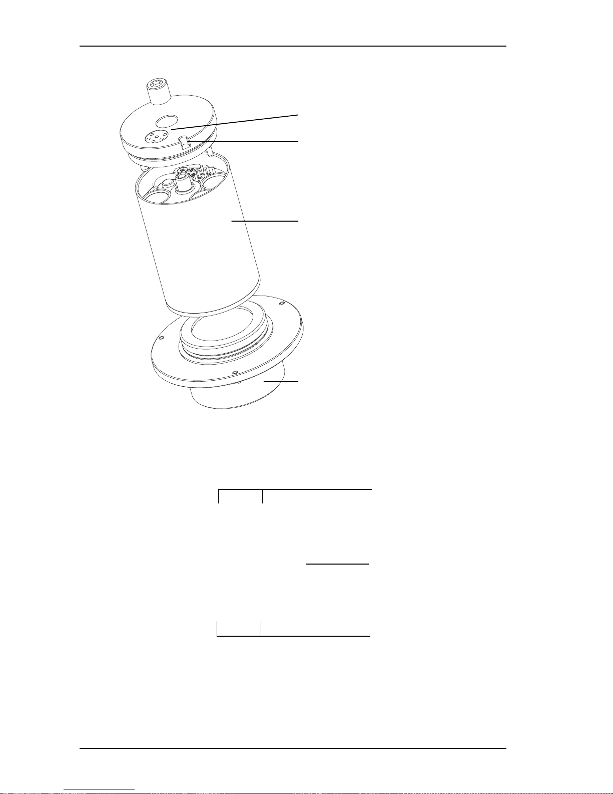
16
electrical contact
Guide slot
SePem base unit (SePem K)
Sensor, shown in the illustration:
SePem G (for noise measurements)
Fig. 2: Structure of a SePem device
3 System Overview
Compartments for
accumulators/batteries
Switch for accumulator/
battery operation
Compartments for
accumulators/batteries
Fig. 3: Opened SePem device (top view)
Page 19

17
3 System Overview
Each SePem device is supplied with four accumulator cells (for-
ming a set) and is ready to use immediately after charging. As an
alternative, also commercially available, non-rechargeable batteries may be used.
SePem devices are additionally provided with a charging automatism ensuring that the SePem devices after automatically char-
ged after being placed in the charging adapter (provided that the
charging adapter is supplied with power).
Note:
Make sure that the screw connection between base
unit and sensor is never loosened by mistake.
Otherwise, problems during the acquisition of
measurement data may occur or moisture may enter
the device.
Page 20
18
3 System Overview
3.1.2 Charging Adapter
The charging adapter permits to recharge
1
and read out up to six
SePem devices at the same time.
Depending on the selected equipment variant, the charging ad-
apter is either integrated into a carrying case or box (see fig. 4
and 5).
Note:
The functionality of both equipment types is identical
- in spite of the differing design.
The charging adapter is provided with:
Six slots for holding the SePem devices
Connector socket (12 V =) for the connection to a power source
Interface for the connection of a further charging adapter (not
indicated in fig. 4, due to its position on the rear of the box)
Interface for the data exchange with a personal computer
Signal LEDs for the indication of operating conditions
The Signal LEDs are located:
between the slots for holding the SePem devices (carrying
box)
OR
on a separate indicator panel (carrying case)
1
SePem devices with inserted batteries cannot be recharged.
Page 21

19
3 System Overview
Fig. 4: Charging adapter with six SePem devices in carrying box
Fig. 5: Charging adapter for six devices in carrying case
Page 22

20
3 System Overview
3.1.3 Power Supply Unit and Cable
The power supply unit is used to connect the charging adap-
ter to the mains.
The communication cable PC <-> charging adapter is used
to connect the charging adapter to the computer on which the
SePem software is installed.
The communication cable charging adapter <-> charging
adapter permits to combine several charging adapters when,
for example, more than six SePem devices are to be used.
The car connection cable permits to connect the charging ad-
apter to the cigarette lighter of a vehicle if no other source of
power is available.
Fig. 6: Power supply unit with mains cable
Page 23

21
3 System Overview
3.1.4 Accessories
Voltage generator
The SePem 02 voltage generator permits to read out signal
LEDs at installation sites with no other available power supply.
The device generates a voltage pulse which is transmitted to the
LEDs of the charging adapter. This permits to read out informati-
on on the current state of the SePem devices directly at the mea-
surement place.
Fig. 7: Voltage generator
Page 24
22
Transport case
The transport case provides space to carry up to twelve SePem
devices. It is lined with resin foam so that the devices can always
be transported with optimum protection.
3 System Overview
Fig. 8: SePem 02 transport case
Note:
Information on other accessories and wearing parts
can be taken from the appendix.
3.1.5 SePem Software
The SePem 02 software permits to perform the following
functions:
Programming the SePem devices
Evaluating measurement data
Page 25

23
4 Installing and Configuring the Software
4.1 Minimum Requirements
4.1.1 Minimum Requirements to the Hardware
IBM-compatible personal computer
at least Pentium II processor, 350 MHz
recommended: Pentium III processor, 600 MHz
working memory 128 MB, recommended 256 MB
at least 80 MB free hard-disk space
graphics card with min. resolution of 1024 x of 768 pixels,
256 colours
serial interface at the PC for data transmission
(at least 57.6 kBit/s)
CD-ROM drive
sound card (optional, for the playback of audible measurement signals)
4.1.2 System Requirements for the SePem Software
Microsoft Windows XP, 2000, NT 4.0, ME, 98SE, 98
Microsoft Internet Explorer 5.01 or higher
Optional:
For calling up the assistant:
Windows 2000/ME/XP or Office 2000/XP
For calling up the help file:
Acrobat-Reader, version 4.0 or higher
4.2 Notes on the CD-ROM
Apart from the SePem software, the supplied CD-ROM contains
further software products from SEWERIN together with the corresponding manuals as PDF files.
The SePem software must be installed and released (see chap-
ters 4.3 and 4.5). The serial number, which is required for this, is
included in the scope of delivery.
All other software products can only be installed as demo versions with reduced functionality. If you decide to purchase one of
these products, we will forward to you the serial number required
for registration.
4 Installing and Configuring the Software
Page 26

24
4.3 Installation from CD-ROM
The procedure for installing the SePem software is as follows.
Exit all Windows programs.
Place the SEWERIN CD in the CD-ROM drive of your
computer. After a short time, the SEWERIN user dialogue
comes up automatically.
4 Installing and Configuring the Software
Fig. 9: SEWERIN user dialogue
Page 27

25
4 Installing and Configuring the Software
Note:
If the SEWERIN user dialogue does not start up
automatically on your computer, open the start.exe
file in the Windows Explorer. You can find this file in
the root directory of the SEWERIN CD ROM.
If problems occur during installation, refer to chapter
12 for troubleshooting measures.
Click on SePem 02 Software (marked with NEU!).
Depending on the computer configuration, the following two
windows may appear:
Window File Download > Select option Run this program
from its current location.
Confirm with OK.
Window Security Warning >Click on Yes.
In the next window, select the desired language . Confirm your
selection with OK. The window for initializing the installation
appears. (This process may take some time.)
Read the displayed instructions. Click on Next. The license
contract appears.
Read the license contract. Select option I accept the license
agreement. Click on Next. A note on network installation
appears.
Read this note. Click on Next. The following window appears:
Fig. 10: Select target directory for SePem software
Page 28
26
Fig. 11: Structure of the SePem directory
In the SePem 02 installation folder, all required program files
are stored automatically.
Take over the suggested installation path by clicking on Next.
OR
Click on Browse if you want to install the SePem software on
another drive (for example D:, E:) or in another directory. Enter
the desired installation path.
In the next window, you can start the installation. To do so, click
on Next.
Note:
Depending on the available computing power of your
PC it may take several minutes before the installation
really starts. The program will be installed correctly
nevertheless.
After finishing installation a corresponding message appears.
Click on Finish. A corresponding message appears on the
screen.
Click on Yes to restart the computer immediately. After restarting
the PC, you can use the SePem software right away. The
SePem icon is added to the Windows desktop.
4 Installing and Configuring the Software
The installation wizard suggests the following destination folder:
Page 29

27
4 Installing and Configuring the Software
4.3.1 Network Installation
Proceed as follows to install the SePem software in a network:
Install the software as described in chapter 4.3.
Read the help text under Start - Programs - Hermann
Sewerin GmbH - SePem 02 - SePem 02 network installation.
Pay attention to the notes and instructions listed there.
4.4 De-installing the SePem Software
Note:
Before de-installing the SePem software, make a
backup of the SePem 02 Data.mdb database. You
can find this file in the installation directory. This
ensures that the saved measurement data is archived.
In the Windows start menu, click on Settings - Control Panel.
Double-click on Add/Remove programs. The Add/Remove
programs window is opened.
Click on Change or Remove Programs.
Select SePem 02 in the list of installed programs.
Click on Remove.
The operating system deletes all SePem program files and
removes the corresponding entries from the Windows registry.
Page 30
28
4.5 Releasing the Software
In order to make full use of the SePem software you must re-
lease it by entering the serial number.
You receive the serial number when purchasing the SePem system.
Note:
You can only communicate with the SePem devices
if the software is released.
Without release you can use only the demo version
of SePem 02 with reduced functionality.
Proceed as follows to release the SePem software:
In the Help menu (”?”), click on Program Release. A new
window appears.
4 Installing and Configuring the Software
Fig. 12: Window for releasing the program
Enter your serial number.
Confirm your entry with OK.
Close the SePem program and restart it.
The software is now released and can be used without restrictions.
Page 31

29
5 Commissioning
It is required to carry out the following steps before the first commissioning and after altering the device numbers or the measurement time scheme:
Assign to the SePem devices only device numbers with max.
two digits.
Recommendation:
Use the last two digits of the FAB number as device numbers
(can be found on the label on the side of the SePem device).
As default, the SePem devices are pre-set conforming to this
recommendation.
Stick-on labels with individual digits are included in the scope
of delivery.
Stick the device number on the SePem devices. Make sure
that the series of digits can be read without problems when the
devices are placed in the charging adapter.
Perform all steps from chapter 6.1 in the prescribed order.
If you do not want to use the last two digits of the FAB numbers
as device numbers, you must change the default setting in the
software.
Enter the new SePem-device numbers under Devices - Adjust
Settings - General - Device Nr. - Change (see chapter
11.2.2.1).
Plan a measurement time scheme, i. e. the cycle with which
the measurements are to be carried out. Enter the desired
scheme under Devices - Prepare for measuring - Meas.
times - New (see chapter 8.3.2).
You can then prepare the first measurement (see chapter 6).
5 Commissioning
Page 32

30
6 Preparing Measurements
Note:
The measurement preparation is described in two se-
parate sections. You always need to perform all
steps from both sections, 1 and 2, to prepare a
measurement completely.
When the system is taken into service for the first time,
it is also required to perform the steps listed under
”Preparation - Part 1”.
6.1 Preparation - Part 1
Switch off your computer, provided that it is switched on.
Place the SePem devices into the slots of the charging adapter.
While doing so, turn the devices slightly until they lock into place.
Note:
Ensure that the SePem devices are correctly locked
in the charging slots. Only then the data transmission
can be performed correctly. During data transmission,
the SePem devices must not be taken from the
charging adapter. If devices with rechargeable
batteries (accumulators) are used, it is required to
charge them before the system is taken into service
(see chapter 9).
6 Preparing Measurements
Connection for
PC connection cable
Power supply connection
Fig. 13: Exterior of the carrying case or box: Connections for power supply
and data exchange at the charging adapter
Page 33

31
Connect the data-exchange cable first to the charging adapter
(port for PC connection cable, see fig. 12) and then to your
computer.
Connect the cable of the power supply unit to the charging
adapter (connector for power supply, see fig. 12).
Connect the plug of the power supply unit to the mains.
Note:
If no other power supply is available at the installation
site, you can also connect the charging adapter to the
cigarette lighter of your vehicle using the car
connection cable.
Switch on your computer and call up the SePem software. (See
chapter 8.1. for further information.)
6.2 Preparation - Part 2
Click on the Help Assistant and select Preparing devices for
measuring (see chapter 8.3).
Enter the measurement places (see chapter 8.3.3).
Print out a distribution list (see chapter 8.3.5).
Note:
You can find a more comprehensive summary of the
basic operating steps in chapter 8.
6 Preparing Measurements
Page 34

32
7 Intended Purpose and Principle of Operation
The SePem 02 system is modularly structured. It is designed to
be used with different sensors. Therefore, it can be used for a
wide range of applications. (See chapter 14 for information on
exchanging sensors.)
7.1 Noise Sensors
SePem devices with inserted noise sensor can be used for
localizing leaks in water-supply distribution systems (remote
detection).
Electro-acoustic processes for localizing water leaks depend to
a large extent on the intensity of the ambient noise. For this reason,
it is often unavoidable to check the pipeline networks during the
night - i. e. outside the regular working hours. The SePem system
is based on sound level measurements and offers a reasonably
priced and efficient alternative to nightshift work.
7.1.1 Functionality and Measuring Principle
The SePem devices take over the sound recording directly on-
site. All present sound signals are amplified and filtered (50 Hz
filter). The sound level is determined using filtered signals.
Noise sensors allow to measure the following:
Volume level
Complete sound samples
7 Intended Purpose and Principle of Operation
Page 35

33
7.1.1.1 Volume Level
The sound volume levels are measured over a pre-set period of
time. During the measurements, the SePem devices record in
specific chronological intervals the present sound level and further statistical data.
Evaluation
When the sound level is very low during the measurement (mea-
sured value close to 0), there is no leakage in the area which
can currently be detected by the SePem devices.
A continuously high sound level is a reliable indicator for a leak,
since it generates a permanent and uniform noise signal (see
also graphics of the measurement details in chapter 11.1.1.10).
The absolute volume of the leak sound level may vary extremely
since this value depends on the size of the leak and the distance
between device and leak.
Consumption noise caused, for example, by water being drawn
off by a consumer, occurs only during the draw-off. Depending
on the quantity of the flow rate, an sound level is generated during the draw-off period reflecting the consumption.
Interfering noise on the other hand, caused by background
noise, cars, etc., generates sound patterns with increasing and
decreasing intensity.
7.1.1.2 Complete Sound Samples
Sound samples are also recorded over a pre-set period of time.
During the measurement, the SePem devices detect internally
the point of time at which the minimum sound level is present.
Then, the measurement is started for a defined time. During the
measurement, all sounds are recorded.
Evaluation
You can listen to the sound sample at the PC. Usually, leaks can
be clearly distinguished from interfering noise.
7 Intended Purpose and Principle of Operation
Page 36

34
7.1.2 Procedures for Recording Data
Basically, the SePem 02 system provides two different approa-
ches for handling data recording.
On the one hand, the individual data loggers can be regularly
moved, for example after one or two measurement nights. For
this purpose, the SePem software provides a wide range of
functions for planning measurement cycles and conditioning
the data which is read out at the end of a measurement period.
On the other hand, SePem devices can be used stationary -
thanks to the GSM module. This extra feature permits to monitor
crucial spots within the pipeline network continuously. Otherwise
these spots could only be controlled with considerable effort.
7.1.3 Problems during the Application of Noise Sensors
The SePem 02 system cannot make a distinction between cer-
tain types of interfering noise, such as pumps, transformers, etc.,
which are generating a steady and uniform sound signal and the
noise generated by leaks.
To detect interfering noise nevertheless, the SePem software is
provided with several options of how to display and evaluate the
measurement results:
Combination of different display types (e. g. frequency spec-
trum, histogram, representation as a chronological function)
Acoustic control with the help of sound samples
7 Intended Purpose and Principle of Operation
Page 37

35
7.2 Installing SePem Devices at the Measurement Location
You can install the SePem devices in defined spaces at the pipe-
line system.
Recommendation for determining proper spacing
Provided that the spacing between the hydrants is 100 m:
metallic pipeline systems: every 2
nd
hydrant
non-metallic pipeline systems: every hydrant
The sound is recorded automatically in user-defined cycles.
Note:
The transmission of the structure-borne sound must
not be dampened by dirt, mud or rust.
If required, clean the coupling positions before
installing the adapter.
The acoustic coupling is realized with the help of various adapters.
The following table is an overview of the adapters and other accessories which can be used for the different types of coupling
positions.
Coupling Adapter/ Remark
position Accessories
Underground Adapter ring Available
2
on the
hydrant SePem device
Hydrant adapter Is used when the SePem
device cannot be completely inserted in the hydrant
mouth due to the construction
of the hydrant
Hydrant combi Can be used for coupling
adapter the adapter the devices to
square-head covers
... Continued on next page
2
Only special versions are delivered without adapter ring.
7 Intended Purpose and Principle of Operation
Page 38

36
Coupling Adapter/ Remark
position Accessories
Slider Hydrant combi
adapter
Pipeline Magnet
Overground Fixed coupling Various couplings to
hydrant & blanking flanges choose from (see offer)
More detailed information on placing the SePem devices can be
found in chapter 8.3.
If the SePem devices are not used for stationary measurements,
they are, for example, collected after two measurement nights
(typical practice-oriented value. They can then be installed at the
next hydrant or connected to a PC for evaluating the data.
Note:
Max. 50 SePem devices can be read out at the same
time.
7 Intended Purpose and Principle of Operation
Page 39

37
7.2.1 Installing SePem Devices on Underground Hydrants
When installing the devices on underground hydrants, you can
select between two variants of how to record the structure-borne
sound:
via the hydrant mouth
via the square-head cover
Recording structure-borne sound via the hydrant mouth
Install the SePem device on the
underground hydrant, using the
adapter ring, as shown in the
illustration.
If required, use additionally the
hydrant adapter (available as an
accessory part) to improve the
coupling.
7 Intended Purpose and Principle of Operation
Fig. 14: Installing SePem device at the hydrant mouth
Page 40

38
Recording structure-borne sound via the square-head
cover
You need a hydrant combi adapter (available as an accessory
part) to record structure-borne sound via the square-head cover.
Screw the hydrant combi adapter
on the SePem device.
Place the SePem device on the
appropriate underground hydrant.
7 Intended Purpose and Principle of Operation
Fig. 15: Installing SePem device at the square-head cover
Page 41

39
7 Intended Purpose and Principle of Operation
7.2.2 Installation on the Conduit Pipe
On metallic conduits, SePem devices with noise sensor record
the structure-borne sound via a magnet.
Screw the D55 magnet (with M10 thread) on the bottom of the
SePem device. This magnet is available as an accessory part.
Place the SePem device, with the magnet pointing down, on
the corresponding conduit.
7.2.3 Installation on Overground Hydrants
Connect the SePem device to the discharge pipe of the
hydrant. While doing so, do not open the hydrant.
Push a protecting tube over the SePem device to protect it
against external influences.
Lock the protective tube to the hydrant using a chain.
Fig. 16: Installation on overground hydrant
Page 42

40
8 Performing Measurements -
The Most Important Steps at a Glance
This chapter describes how to perform measurements with the
SePem devices. In addition, it includes a comprehensive over-
view of the most important actions which you need to perform
after the measurements.
Topic-wise, the chapter picks up the thread of chapter 6. This
means, before carrying out the following actions you must first
prepare the measurement as described in chapter 6.
You can find more detailed information, as well as numerous tips
and instructions, on how to make optimum use of the SePem
software in chapter 11.
8.1 Starting the Program
Start the SePem software in the Windows start menu (Start -
Programs - Hermann Sewerin GmbH - SePem 02 - SePem
02)
OR
use the SePem icon on the Windows desktop.
When the program is started the first time, a welcome window
appears.
Uncheck the check box Don’t show this dialog again if you
want to skip the welcome screen the next time the program is
started.
Close the window with OK.
The SePem user interface appears from which you can select
all software menus and functions.
8 Performing Measurements - The Most Important Steps at a Glance
Page 43

41
Fig. 17: User interface of the SePem software
1 2
4 5 63
1 Menu bar
2 Icon bar
3 Status bar
4 Status field
5 Number of SePem devices which are currently inserted in the
charging adapter
6 Signal field; indicating the status of data transmission
8 Performing Measurements - The Most Important Steps at a Glance
Page 44

42
Fig. 18: Advice and guidance of the Assistant (optional)
8.2 Calling Up the Help Assistant
The Microsoft Help Assistant guides you safely through the Se-
Pem software. Speech balloons are used to suggest the next
logical steps which can be taken. In addition, it provides help and
advice.
It goes without saying that you can also use the program without
the Assistant. Just use the various menus. The most important
actions can also be started with function keys on the keyboard
(for example, key F5 opens the Show measurement data win-
dow).
8.2.1 Fading In/Out the Help Assistant
You can use a toggle button to fade in/out the Help Assistant.
Click on the Enable/disable help agent button in the icon bar.
OR
In the Settings menu, select the item Help assistant.
Note:
If you cannot call up the Help Assistant, check whether
this optional feature is really installed on your computer
(see chapter 8.2).
8 Performing Measurements - The Most Important Steps at a Glance
Page 45

43
8.2.2 Installing the Help Assistant Later On
If you want to install the Help Assistant later on, you can find the
required program on your Microsoft Windows/Office CD ROM
(2000 or XP). You can find it under the path: Features to install
- Office Shared Features - Office Assistant.
You can also download the Help Assistant from the Internet (http:/
/www.microsoft.com/msagent/resources.htm, keyword ”Downloads”).
When installing the Assistant, you may select one or several animations.
8 Performing Measurements - The Most Important Steps at a Glance
Page 46

44
8.3 Placing SePem Devices
Before placing the SePem devices you must first program them.
The following data is required:
Date and time of the first measurement
Duration of the individual measurements
Cycle in which the measurements are to be executed
The two last items are part of the so-called ”measurement time
scheme” (see chapter 8.3.2).
If you want to work with the Help Assistant:
Click on Preparing devices for measuring in the speech
balloon of the Assistant.
OR
If you do not want to use the Help Assistant:
Click on Devices - Prepare for measuring or press F9 on the
keyboard.
Note:
The following screens are examples, illustrating typical
application situations. Therefore, they can differ from
your individual application situation.
At first, a window is opened in which the data transmission
between SePem software and devices is indicated.
Fig. 19: Read device window
8 Performing Measurements - The Most Important Steps at a Glance
Page 47

45
Note:
Before starting the data transmission, make sure that
the SePem devices are correctly inserted and locked
in the charging slots (screw in the devices carefully
until they audibly lock in).
During data transmission, the SePem devices must
not be taken from the charging adapter.
After transmitting data to the SePem devices, the Expose
devices window is opened.
8 Performing Measurements - The Most Important Steps at a Glance
Fig. 20: Expose devices window
8.3.1 Entering the Date of the First Measurement
The date of the first measurement determines on which day a
series of measurements is started (see measurement time scheme, chapter 8.3.2).
Click on the arrow on the right-hand side of the First
measurement at field. A calendar appears on screen.
Click on the desired date on which the first measurement is to
be started. The calendar field is closed and the selected day is
automatically taken over in the Expose devices window.
Page 48

46
8.3.2 Setting Up or Modifying a Measurement Time Scheme
The SePem software functions are based on a measurement time
scheme. The measurement time scheme is used to determine
when the measurements are to be started, how long they should
take and in which cycles they are to be performed (for example,
on five consecutive days with two measurements per night). Measurement time schemes offer the advantage that the measurement times need only to be entered once.
The scheme contains a varying number of entries which are
modifiable.
After installing the software, the measuring-time scheme is still
empty. This means, before placing the SePem devices for the
first time the required data has to be entered or modified.
Proceed as follows if you want to set up or modify the measurement time scheme:
Click on the Meas. times button in the Expose devices window.
The Adjust measurement scheme window is opened.
Fig. 21: Adjust measurement scheme window
8 Performing Measurements - The Most Important Steps at a Glance
Page 49

47
The entries in the Adjust measurement scheme window will
be taken over in the Expose devices window when the window
is closed.
Close the Adjust measurement scheme window with
OK if you want to take over the entered measuring-time scheme
only for the planned series of measurements
OR
Save to store the measurement time scheme permanently.
Then, close the window with OK.
Registering new entries
In the Adjust measurement scheme window (fig. 21), click on
New.
The Create new entry window is opened.
Enter the desired values in the
input fields. For detailed
information on the individual
fields refer to chapter 11.2.1.1.
Confirm your entries with Accept.
Fig. 22: Create new entry window
Changing entries
In the list of measurement time schemes (Adjust measurement
scheme window, fig. 21) double-click on the entry which you
want to change. The Change entry window is opened.
Change the values as desired.
Confirm your entries with Accept.
8 Performing Measurements - The Most Important Steps at a Glance
Page 50

48
Fig. 23: Select project window
8.3.3 Entering Project Names and Measurement Places
Project names and specifications on the measurement place (e.
g. place, street, hydrant number) help you to set up a plan for
placing the devices. This permits to place SePem devices easier.
Selecting existing and entering new project names
In the Expose devices window (fig. 20), click on Project. The
Select project window appears. If project names are already
available, you can select an entry from the indicated list.
8 Performing Measurements - The Most Important Steps at a Glance
Select the desired project name if you want to assign it to the
current measurement. Click on Accept.
OR
Click on New if you want to enter a new project name.
See chapter 11.1.1.6 for further information.
Selecting available or entering new information on the
measurement place
In the Expose devices window, select the data record for which
you want to enter information.
Click on Meas. place. The Edit measurement places window
is opened. If measurement places are already available, you
can select an entry from the indicated list.
Page 51

49
Fig. 24: Edit measurement places window
Fig. 25: Change measurement place window
Select the desired measurement place if you want to assign it
to the current measurement. Click on Accept
OR
Click on New if you want to enter a new measurement place.
See chapter 11.1.1.7 for further information.
8.3.4 Defining Device Changes
You can pre-set the point of time at which a SePem device is to
be placed at a new measurement place. This requires that a measurement place was assigned to the device beforehand.
In the Expose devices window (fig. 20), assign a measurement
place to the appropriate measurement (i. e. the device), provided
that you did not do it yet (see previous section).
Double-click on the desired measurement. The Change
measurement place window is opened.
Enter the desired date (day, time) and confirm it with OK.
8 Performing Measurements - The Most Important Steps at a Glance
Page 52

50
8.3.5 Transmitting Settings to the SePem Devices and Printing
Out a Distribution List
Finally, all entered settings need be transmitted by the PC to the
SePem devices.
Distribution lists make it easier to obtain a general overview which SePem
device is to be placed where and when for measurements. The distribu-
tion printouts include the information required for placing all SePem
devices at a different location (date and time, installation site, precise
place of the measurement and designation of the hydrants). A sample pattern of a distribution list is included in the appendix.
Distribution lists can be printed out via the Expose devices window
using the Print button. If you do not want to start a printout right away,
an appropriate message will appear after starting the data transmission. You can then start the printout in the displayed message window.
Click on Accept in the Expose devices window. A message
appears on screen.
Click on Yes to start the list printout.
Note:
Always print out a distribution list before placing the
SePem devices!
After the data is transmitted successfully, a corresponding
message is indicated on-screen. During data transmission the
Expose devices window is automatically closed.
8.4 Placing SePem Devices
After having programmed the SePem devices as laid out in the
preceding sections, you can now place them at the desired measurement places. Adhere to the installation instructions and tips
listed in chapter 7.2!
Note:
When placing SePem devices, make absolutely sure that
they are really placed at the prescribed measurement
places. Otherwise mistakes cannot be ruled out. Only
then the data can be evaluated correctly.
8 Performing Measurements - The Most Important Steps at a Glance
Page 53

51
8.5 Collecting SePem Devices
After the measurements, the SePem devices can be picked up at
the measurement places again.
You can then proceed with reading out the measurement data
(see chapter 8.6).
8.6 Reading Out SePem Devices
Place the SePem devices into the slots of the charging adapter.
Note:
Ensure that the SePem devices are correctly inserted
and locked in the charging slots.
During data transmission, the SePem devices must
not be taken from the charging adapter.
Start the SePem software.
To start reading out the SePem devices, open the Devices -
Read measurements menu or press function key F10.
The transmission progress between SePem devices and PC is
indicated. The measurement data is stored in the SePem
database. After the transmission the Show measurement data
window is opened. Each line of the displayed table represents
an individual measurement.
Fig. 26: Show measurement data window
8 Performing Measurements - The Most Important Steps at a Glance
Page 54

52
8.7 Showing Stored Measurements
The measurements listed in the Show measurement data win-
dow (fig. 26) can be edited as follows:
Selective display of specific measurements with the help of filters
and control fields
Indication of the appropriate graphics (max. four measurements
can be displayed at the same time); four different types of
representation can be selected
Assignment of projects, measurement places and/or
modification of data which is already assigned
Deletion
Entries can be selected and deleted just like in the Microsoft Windows Explorer. You can, for example, select several lines for furt-
her editing by holding down the Ctrl key, or you can delete the
selected line(s) by pressing the Del key on the keyboard. A detai-
led description of all other functions can be found in chapter 11.1.1.
Note:
The buttons on the bottom edge of the screen (e. g.
Project, Meas. place, Details) are only available after
selecting one or several lines in the table.
Depending on the default setting, the table may have more co-
lumns as can be shown in the Show measurement data win-
dow. You can access these hidden columns with the help of the
scroll bar at the bottom edge of the table. Refer to chapters 11.1.1.2
and 11.1.1.3 for notes on setting up and adjusting the table (e. g.
selection of columns).
8.8 Printing Out Measurement Data
Proceed as follows if you want to print out measurement data:
Open the Show measurement data window.
(For detailed information refer to chapter 11.1.1.)
Select the measurement(s) which you want to print out from the table.
Click on the Print icon in the icon bar. The Print window is opened.
Select the desired printing options. (For detailed information
refer to chapter 11.1.5.)
8 Performing Measurements - The Most Important Steps at a Glance
Page 55

53
9 Power Supply of the SePem Devices
The SePem devices can be used with both - batteries as well as
rechargeable accumulators. Depending on the used type of battery or accumulator, the maximum operating time may vary.
Accumulators must be recharged in regular intervals. This can
either be done using the power supply unit or via a car battery.
Detailed information on the technical specifications of the power
supply can be found in the appendix.
Chapter 2.4 contains information on the in-service conditions.
9.1 Accumulator Operation
Thanks to the integrated accumulator management system it is
practically impossible to overcharge or damage accumulators.
The integrated electronic system monitors the charging process
and switches automatically to charge retention.
It is recommended to recharge the accumulators regularly after
finishing a series of measurements. This ensures that your Se-
Pem devices are always ready to use.
Note:
On delivery the accumulators are not completely
charged! For this reason, charge the accumulators
for 14 hours before taking them into service!
Note:
When charging SePem devices in the carrying case
variant, make absolutely sure that the lid remains
open during charging.
Otherwise the devices will be charged extremely slowly
due to the heat development in the closed case.
9 Power Supply of the SePem Devices
Page 56

54
9.1.1 Charging Devices with the Help of the Plug-In Power
Supply
Place the SePem devices in the charging adapter. Then, connect
the power supply unit to the power supply connector (see fig. 13).
Note:
Use only the original SEWERIN plug-in power supply!
Only with this unit it is permitted to charge the devices
unattended.
9.1.2 Charging Inside a Vehicle
Place the SePem devices in the charging adapter. Then, connect
the car connection cable (available as accessory) to the power
supply connector (see fig. 13).
9 Power Supply of the SePem Devices
Page 57

55
Fig. 27: Signal indicators on the charging adapter - box type
SePem K
Fig. 28: Signal indicators on the charging adapter - carrying case type
10 Signal Indication on the Charging Adapter
The signal indicators inform on the current operating status of the
SePem devices.
10.1 Position of the Signal Indicators
The exact position of the signal LEDs depends on the type of
charging adapter. The functionality of the signal indicators is identical for both types of charging adapter (carrying case and box).
Box
The LEDs are arranged in groups
of three (red, yellow, green)
directly under and/or over the
appropriate charging slots.
Carrying case
The signal LEDs of all charging
slots are arranged on a separate
indicator panel on the left-hand
side of the carrying case.
10 Signal Indication on the Charging Adapter
Page 58

56
10.2 Preparing the Signal Indicator Query
The current operating status of the SePem devices can be que-
ried any time. You only require the following accessories:
Accessory Application field
Power supply unit 230 V power supply available
Car connection cable Permits queries ”on the spot”, provided
that a car is available
Voltage generator Permits queries ”on the spot”, provided
(accessory) that no mains connection is available
10.2.1 Query with Available Power Source
Place the SePem devices into the slots of the charging adapter.
Connect the cable of the power supply unit, or the car connection
cable, to the charging adapter (connector for power supply, see
fig. 13).
10.2.2 Query Using a Voltage Generator
Use a voltage generator (accessory) for querying devices when
no mains connection is available at the installation site.
Connect the voltage generator as shown in fig. 29.
Press the key on the voltage generator and hold it in that
position. After approx. 2-3 seconds the LEDs start to flash.
Fig. 29: Connection of the voltage generator
10 Signal Indication on the Charging Adapter
Page 59

57
Fig. 30: LED indicators during accumulator operation
Read the signal indicators with the key kept pressed down.
You have approx. 5 seconds for reading. After that, the LEDs
stop flashing.
Release the key of the voltage generator.
Why?
SePem devices with batteries The display goes out.
SePem devices with The charging mode starts
accumulators automatically. For this, the
available power source is used.
This means that the battery of
the voltage generator is used,
therefore rapidly discharging it.
10.3 Operating Principle and Meaning of the Signal Indications
The signal indicators inform on:
Status of data evaluation (flashing phases)
Operating status of the accumulators, provided that
accumulators are inserted in the devices
10.3.1 Operating Principle
SePem devices with batteries
After preparing the signal indication (see chapter 10.2), the data
evaluation is lit for approx. 5 seconds. After that, the indication
goes out.
If you need the signals indication again, you must re-connect the
power supply (by pulling the connector first, then replugging it).
SePem devices with accumulators
After preparing the signal indication (see chapter 10.2), the data
evaluation is displayed for approx. 5 seconds. This is followed
by a pause of approx. 3 seconds, i. e. all LEDs go out. After that,
the charging status of the accumulators is indicated continuously.
10 Signal Indication on the Charging Adapter
Page 60

58
10.3.2 Meaning of the Signal Indications
The red and green LEDs are pre-set ex-works (exception: green
LED, flashing). The default settings can be individually adjusted
(see chapter 11.2.2.4).
The yellow LEDs have a fixed-assigned meaning which cannot
be changed.
LEDs with default setting, freely configurab le
Indication
Data evaluation Indication charging
red flashing Accu is excessively
discharged or working
in reduced charging
mode
(temperature > 50° C)
red steady Measurement Charging operation
light evaluation exceeds
threshold value
(3 % of end value)
green steady Measurement Charge retention
light evaluation falls below
threshold value
(3 % of end value)
LED without default setting, freely configurable
green flashing
LEDs with fixed-assigned meaning (unchangeable)
Description Remedy
yellow flashing Error Start diagnostics
(see chapter 11.2.4)
yellow steady Device not Contact SEWERIN
light ready to operate customer service
10 Signal Indication on the Charging Adapter
Page 61

59
11 Menus and Functions of the SePem Software
This chapter describes in detail all menus and functions of the
SePem software. The structure of the chapter corresponds to the
order of menus in the menu bar, i. e., the description starts with
item Show measurement data in the File menu and ends with
item Info about SePem 02 in the Help (?) menu.
11.1 File Menu
The File menu comprises the following functions:
Show measurement data
Handle measurement places and comments
Repair and compress database
Import of measurement data
Export of measurement data
Print
Adjust page settings
Close (for exiting the SePem program)
11.1.1 Show measurement data
The SePem software indicates stored measurement data in a
separate window.
In the menu bar, click on File – Show measurement data.
OR
Click on Show stored measurements in the icon bar.
OR
Press key F5 on the keyboard.
11 Menus and Functions of the SePem Software
Page 62

60
Fig. 31: Show measurement data window
Each line of the table represents an individual measurement.
These measurements can be generated by various SePem
devices.
The table can be configured individually. It is possible to adjust
or select the following:
Sorting of the measurement data
Width of columns
Selection of columns which are to be displayed on-screen or
faded out
Order of columns
You can use the scroll bar (at the bottom of the table) to access
columns which are lying outside of the display area.
Selecting measurement data (lines)
Selection of 1 line Click with left mouse button
Selection of several lines Shift key and + click with left mouse
(grouped together) button
selection of several CTRL key and + click with left
individual lines mouse button
11 Menus and Functions of the SePem Software
Page 63

61
Key functions for editing measurement data
Deleting line(s) Select line(s), then press the DEL key
Reading out individual Select line(s), then
sound data records Press letter A (see chapter 11.2.3.1)
Assigning projects, Select line(s), then
measurement places, Press letter D (see chapter 11.1.1.7)
storing comments
11.1.1.1 Sorting measurement data
Any column can be used as a criterion for sorting the order of
measurement data.
Click on the header of the column whose entries are to be used
for sorting the measurement data.
The measurements are immediately displayed in ascending order (i. e., for letters: A > Z). At the same time, a small white sorting arrow appears in the column header.
Fig. 32: Measurements – sorted according to starting date
If you now click again on the column header, the sorting order
is reversed (for letters: Z > A). The sorting arrow points downwards.
11.1.1.2 Changing the column width
Move the mouse over the header of the column whose width
you want to change.
Press the left mouse button as soon as the mouse pointer
changes into a double arrow (<->).
Move the lateral borders of the column until it has the desired
width.
Release the mouse button.
11 Menus and Functions of the SePem Software
Page 64

62
11.1.1.3 Selecting column for the measurement data table
The table in the Show Measurement data window can contain
up to 31 different measurement parameters (fig. 31). The number
and sequence of columns can be determined individually.
The stored settings are taken over for printing out the
measurement data.
Overview of the selectable measurement data information
FAB No. Serial number of the SePem device
Device No. User-definable number (see chapter 5)
Status graphics Indication of the measurement status
with the help of color symbols
Red An error has occurred, measurement
not performed
Green Measurement finished successfully
Yellow A problem has occurred, the displayed
measurement result may be incorrect
(e. g. when a SePem device is not ta-
ken out of the charging slot before the
measurement starts)
Status text Comment or description of the measu-
rement status
Start date Day of the measurement start
Start time Time of the measurement start
Stop date Day of the measurement end
Stop time Time of the measurement end
Evaluation A, B, C Depending on the used sensor type and
selected sensor settings (see following
table)
Evaluation A, B, C Depending on the used sensor, sche-
(Graphics) matic representation of the measure-
ment result
Info evaluation A, B, C Depending on the sensor type (see fol-
lowing table)
Temperature (° C) Ambient temperature measured at the
beginning of the measurement
11 Menus and Functions of the SePem Software
Page 65

63
Transfer Day at which the SePem devices are
transferred
Measurement type The type of measurement (Time, event
or stationary measurement)
Measurement interval Interval between two 2 measurement
(in sec.) values
Project User-definable name (e. g. ”Town cen-
tre”)
Measurement place #1 Information on the point of measure-
ment (e. g. street name)
Measurement place #2 Information on the measurement place
(e. g. place name)
Hydrant Designation of the hydrant
Comment Comment on the measurement
Channel 1, 2, 3, 4 Display of the measuring range of the
appropriate channel (e. g. noise sensor=1-channel sensor, combined temperature/pressure sensor=2-channel
sensor, etc.)
Next service Suggestion for the next scheduled ser-
vice
Last service Last registered service
Parameter - Info evaluation A, B, C for noise sensors
Display Description
A 5 % level (minimum) minimum measurement value
B 5 % level (filtered) This value is required when a GSM
module is used
C Spectrum of the Deviation from the mean value measu-
rement
If only a single sensor type is used, the parameter Info evaluation
is not available.
In this case, instead of Evaluation A , B, C, the column headers
5 % level (minimum), 5 % level (filtered) and/or Width are
indicated.
11 Menus and Functions of the SePem Software
Page 66

64
Configuring the table (selection of columns)
Click with the right mouse button on the table of measurement
data. A menu pops up.
Click with the left mouse button on the item Adjust table. The
window Adjust measurement data table appears.
Fig. 33: Window Adjust measurement data table
You can now change the order, status (enabled/disabled) and
format (only for numerical fields) of every individual parameter.
Double-click on the line which you want to edit.
The Change measurement data table window appears.
Fig. 34: Window Change measurement data table,
modification of parameter Evaluation A
Perform the desired changes. A tick in the check box Activate
means that the column will be displayed in the measurement
data table.
Click on Accept.
In the Adjust measurement data table window, click also on
Accept to apply the changes to the table view.
11 Menus and Functions of the SePem Software
Page 67

65
11.1.1.4 Generating the history log of a specific measurement place
or project
All measurement data records which are assigned to a specific
measurement place or project (see also chapter 11.1.1.7), form
the history of this particular project or measurement place.
Select a line in the Show measurement data window (fig. 31)
which is containing measurement data of a particular measurement place or project whose history you want to generate.
Optionally, you may select the options only same project or
only same meas. place (a tick appears in the appropriate check
box when the option is selected). The corresponding data records
are immediately filtered and shown in the Show measurement
data window.
If you select both check boxes, the history of a specific measurement place belonging to a particular project will be indicated.
After disabling the options (i. e. no tick in the check boxes) all
data records are indicated again.
11 Menus and Functions of the SePem Software
Page 68

66
11.1.1.5 Setting filters
Filters can be used to perform precise and fast search runs for
specific measurement data records included in the SePem
database. Filters are very convenient, for example, if you want to
call up the results of a specific day, interval, place or device.
You can use the following options:
fixed-assigned (pre-defined) filter schemes
freely configurable filters
Both filter options can also be combined with each other. In
addition, you may also set up new filter schemes.
Note:
Select item Filter settings only with schemes if you
want to block the freely configurable filter function. You
can select this item following the path: Settings –
Program settings – Miscellaneous area.
Click on Filter in the Show measurement data
window (fig. 31).
The Filter settings window is opened.
Fig. 35: Filter settings window with simple, freely configurable filter
11 Menus and Functions of the SePem Software
Page 69

67
The following section deals with the various possibilities made
available by the filter settings.
Close the Filter settings window (fig. 35) with OK. The de-
fined filter(s) will then be used. The Show measurement data
window is updated and shows only the relevant (i. e., filtered)
measurement data.
Using a pre-defined scheme
In the Scheme area, select the desired filter using the selec-
tion arrow.
Configuring simple, freely configurable filters
In the Scheme area, select filter item [none].
You can now select or enter parameters in the Elements area
of the screen.
Select under Field the parameter (e. g. Project, FAB No.) which
you want to filter in the measurement data table.
Select under Compare the operand which you want to use for
filtering (<, <=, = >, >=).
Enter the desired parameter(s) in the Values field. Enter either
the appropriate numerical values (e. . date, FAB no.) or use the
following entries:
[NOW] Wildcard for the current date
[YEAR] Wildcard for a specific year
[MONTH] Wildcard for a specific month
[DAY] Wildcard for a specific day
+, -, *, / For adding up, subtracting, multiplying, dividing
( ) Brackets for arithmetic operations
Note: At the end of this chapter you can find two examples of
how to use wildcards and operators.
Click on the adjacent Add button. The filter appears in the Fil-
ter settings area.
11 Menus and Functions of the SePem Software
Page 70

68
Combining several single filters to a total filter
Determine the first filter as described in the preceding section
or select a pre-defined scheme.
Select under Association the desired Boolean parameter (OR,
AND, NOT). Click on the adjacent Add button. The filter appears in the Filter settings area.
Determine a second filter as described in the preceding sec-
tion. (You cannot use a pre-defined scheme for this.)
You can extend now the combined filter by adding other filters
and associations.
You can undo your entries or the entire filter with <<.
Use the bracket buttons ( and ) to define the priority of opera-
tors, if required.
Creating a new scheme
Filters which are frequently used can be stored as schemes. These
schemes make working easier since you need not enter individual
parameters several times. Just open the required scheme.
Define a simple or a combined filter.
in the Scheme area, click on the Add button. The Save scheme
window is opened.
Enter a scheme name in the input field and confirm with OK.
The new system is immediately available in the table of
schemes.
Deleting a scheme
In the Scheme area, select the scheme which you want to de-
lete using the selection arrow.
Click on the adjacent Delete button.
11 Menus and Functions of the SePem Software
Page 71

69
Example of a simple, freely configurable filter
After entering filter
START DATE = [NOW] – [MONTH]
the data records of the last month are indicated.
Optionally, you may also define the above filter as follows:
START DATE = [NOW] + ([YEAR] – 13 * [MONTH])
Example of a combined filter
Fig. 36 shows the settings for defining the following combined
filter:
FAB No. = 096 01 000001 AND START DATE >= [NOW] – 4 *
[MONTH]
This filter is used to determine the measurement data of the
SePem device with FAB no. 096 01 000001 which were measured
during the last four months.
Fig. 36: Filter settings window with combined filter
11 Menus and Functions of the SePem Software
Page 72

70
11.1.1.6 Defining and assigning projects
Projects (or project names) are freely definable designations which
can be assigned to one or several measurements. Projects help
to make managing and administering measurement data easier
and more efficient.
In the Show measurement data window (fig. 31), select a line
which you want to assign to a specific project or whose project
assignment you want to change.
Click on the Project button.
The Select project window appears.
Fig. 37: Select project window
The Select project window includes all projects which are al-
ready set up.
Select the desired project name.
Click on Accept.
The selected project name is taken over for the highlighted
measurement (Show measurement data window).
Entering new project names
Click on the New button. The Create new project name win-
dow is opened.
Enter the new project name in the text field.
Store the entry with Accept.
11 Menus and Functions of the SePem Software
Page 73

71
Changing existing project names
Double-click on the project name which you want to change.
The Change project name window appears.
Change the entry in the text field.
Store the change with Accept.
Deleting project names
Select the desired project name.
Click on the Delete button. The project name is deleted from
the table of selectable projects.
Even if the deleted project name does no longer appear in the
Select project window, already existing links between the deleted project and the measurement data are maintained (Show
measurement data window, fig. 31).
11.1.1.7 Defining and assigning measurement places
Measurement places and supplementary comments are used to
describe the measurement data with more details. These entries
can be freely defined and assigned to one or several
measurements.
In the Show measurement data window (fig. 31), select a line
for which you want to assign a measurement place or comment or whose measurement place or comment you want to
change.
Click on Meas. place. The Edit measurement places and
comments window appears.
11 Menus and Functions of the SePem Software
Page 74

72
Fig. 38: Edit measurement places and comments window
The window has two separate tabs (Measurement place, Com-
ment). Click on the desired tab to open it. Function-wise, both
tabs are similarly structured. All measurement places and/or
comments which were already entered are listed on the appropriate tabs.
Select the desired measurement place or comment.
Click on Accept.
The selected measurement place or comment is taken over for
the highlighted measurement (Show measurement data win-
dow, fig. 31).
Perform the steps described in the above section if you want
to enter new measurement places or comments or if you want
to delete or change existing entries (chapter 11.1.1.6).
11.1.1.8 Cancelling existing assignments between projects,
measurement places, comments and measurement data
In the Show measurement data window (fig. 31), select one
or several lines whose assignment(s) you want to cancel.
Press the letter D (delete) on the keyboard. The Delete en-
tries window appears.
Select one or several desired options (Projects, Measurement
places, Comments).
Click on the Delete button. The assignment(s) is (are) can-
celled.
11 Menus and Functions of the SePem Software
Page 75

73
11.1.1.9 Representing measurement data graphically
The SePem software is also capable of representing measurement
data graphically. It is possible to call up the trend curves of up to
four different data records at the same time.
Depending on the used type of sensor, up to four graphic display
options are available:
Time
Intensity
Histogram
Frequency spectrum
Which options are available depends on the used type of sensor!
Note:
Define under Settings – Program settings – Set-
tings – Display type – Details area the graphic type
to be used as default when the Details windows is
opened (see chapter 11.3.1.2).
In the Show measurement data window (fig. 31) select one,
two, three or four line(s) whose measurement data is to be
represented graphically.
Click on the Details button. The Details window is opened.
11 Menus and Functions of the SePem Software
Page 76

74
Fig. 39: Graphic display of four measurement data records
Each measurement data record is indicated as a separate dia-
gram. If only a single line is selected in the Show measure-
ment data window, only a single diagram will be displayed
in the Details window.
Select under Display the desired type of representation.
Supplementary functions for evaluating and analysing data
Position Indication of the current cursor position in the
trend display (including co-ordinates on thex/
y axis)
Scale autom. Optimised representation of the curve trend
Fade in additional Indication of evaluation details
info
Legend Display of a legend informing about the
used type of sensor
Audio function Audible play-back of measurement data;
(button) only available for noise sensors; independent
of display type; technical requirement: sound
card
11 Menus and Functions of the SePem Software
Page 77

75
It depends on the selected display type which supplementary
function is available or not.
Display type Available supplementary function
Position Scale Fade in Legend
autom. additional info
Time X X X X
Intensity X X X X
Histogram X X – X
Frequency spectrum X – – –
Zoom function (for enlarging the display)
You may zoom in the reading area of all display types – except for
the frequency spectrum – with the help of the zooming function.
Move the mouse over the trend display.
Keep the mouse button pressed and move the mouse to draw
a rectangle. The measurement places within the rectangle are
zoomed in.
Double-click on the rectangle to return to the standard display.
Note:
A section can only be zoomed in once. If required,
return to the standard display by double-clicking on
the trend display. Then, zoom in a new rectangle.
11 Menus and Functions of the SePem Software
Page 78

76
11.1.1.10 Interpreting trend curves for different display types
The following section includes information which may help you to
interpret measurement details correctly. Two illustrations are
available for each display type: one with leakage and one without.
Note:
All illustrations included in this chapter refer to meas-
urements with the noise sensor. If other sensor
types are used the trend curves may either look completely differently or are not available.
Time display for noise sensor
Time is represented on the x axis, The y axis is provided with a
measurement value scale. Users can assign the indicated signal
peaks to specific events.
A constantly present noise level (significantly larger than zero)
may indicate a leak (fig. 40).
If the constantly present noise level is close to the zero level, it is
less likely that a leak has occurred (fig. 41).
Short, high-level noise signals indicate, for example, cars which
are passing by or water being drawn off by a consumer.
11 Menus and Functions of the SePem Software
Page 79

77
Fig. 40: Measurement data as a chronological function – high leak probability
Fig. 41: Measurement data as a chronological function – low leak probability
11 Menus and Functions of the SePem Software
Page 80

78
Intensity display for noise sensor
Time is represented on the x axis, The y axis is provided with a
measurement value scale. The measured levels are sorted
according to their sound volume.
If the trend curve runs flat, only few interfering noise signals have
occurred. The steeper the curve, the more interfering noise signals
(e. g., cars which are passing by or water being drawn off) were
detected.
A high starting point of the curve (t = 0) on the y axis indicates a
permanent noise level, and thus also a leak (fig. 42).
If the starting point of the curve (t = 0) on the y axis lies close to
zero, the leak probability is small (fig. 43).
11 Menus and Functions of the SePem Software
Page 81

79
Fig. 42: Intensity display of the measurement – high leak probability
Fig. 43: Intensity display of the measurement – low leak probability
11 Menus and Functions of the SePem Software
Page 82

80
Histogram display for noise sensor
If the measurement data is displayed as histogram, the frequency
of every recorded level signal is represented as percentage values.
Time is represented on the x axis, percentages on the y axis.
The shape of the signal level indicates the quality of the
measurement:
good measurement:
small gaps between level values = narrow cone
bad measurement:
large gaps between level values = wide cone
The leak probability depends on the distance between minimum
level and zero point. The minimum level is defined as the smallest
measured value represented in the percentage display (i. e. at
the left edge of the trend curve). Outliers, i. e., individual small
peaks deviating from the actual curve, are not considered in this
case.
The leak probability is high if the gap between minimum level and
zero point of the x axis is large (fig. 44).
If the minimum level lies close to the zero point of the x axis, the
leak probability is small (fig. 45).
11 Menus and Functions of the SePem Software
Page 83

81
Fig. 44: Measurement data as histogram – high leak probability
Fig. 45: Measurement data as histogram – low leak probability
11 Menus and Functions of the SePem Software
Page 84

82
Frequency spectrum display for noise sensor
This display type is used to reproduce the measured audible
signals as a FFT function (FFT = Fast Fourier Transformation).
The sound is analysed and broken down into individual sine tones.
This means that, unlike at the other display types, not the sound
volume, but the recorded sound as such is analysed.
The y axis represents the sound volume (relative values), the x
axis the frequency.
If the curve has a wide, uniformly increasing/decreasing shape
above the background noise, it is highly probable that the (entire)
noise represents a leak (fig. 46).
If the curve, on the other hand, contains individual narrow peaks
which are deviating extremely from the baseline, a leak is not
very likely (fig. 47).
11 Menus and Functions of the SePem Software
Page 85

83
Fig. 46: Frequency spectrum of a measurement –
the sound represented in the display is probably a leak noise
Fig. 47: Frequency spectrum of a measurement –
the sound represented in the display is no leak
11 Menus and Functions of the SePem Software
Page 86

84
11.1.2 Editing measurement places and comments
Measurement places and comments are used to describe
measurement data in detail. They can be entered or deleted
without independent from the relevant measurement places and
comments.
You can therefore manage all measurement places or comments
separately, so that you only need to assign them to the
measurement data (see chapter 11.1.1.7).
In the menu bar, click on File – Handle measurement places
and comments. The Edit measurement places and comments window appears.
Fig. 48: Edit measurement places and comments window
The window has two separate tabs (Measurement place, Com-
ment). Click on the desired tab to open it. Function-wise, both
tabs are similarly structured. All measurement places and/or
comments which were already entered are listed on the appropriate tabs.
Then, close the window with OK. All changes are stored.
Entering new measurement places/comments
Click on the New button. Either window Create new measure-
ment place or Create new comment appears.
Enter the new measurement place or comment in the text field.
Store the entry with Accept.
11 Menus and Functions of the SePem Software
Page 87

85
Changing a measurement place or comment
Double-click on the measurement place or comment which you
want to change. Either window Change measurement place
or Change comment appears.
Perform the desired changes.
Store the changes with Accept.
Deleting a measurement place or comment
Select the measurement place or comment which you want to
delete.
Click on the Delete button. A message appears on screen.
Confirm the deletion with Yes. The entry is removed from the list of
registered measurement places or comments.
Note that already existing links between the deleted measurement place or comment and the measurement data are maintained!
11 Menus and Functions of the SePem Software
Page 88

86
11.1.3 Repairing the database
All measurement data records are stored in the SePem database.
This database can be compressed and repaired in a single
step.
The repair function is particularly useful when a system error
occurs during storing or loading the database.
Note:
If the SePem database contains a high number of
measurement data records, you can reduce the access time by compressing the measurement data.
In the menu bar, click on File – Repair and compress data-
base. After a short time a message appears on screen that the
database was compressed and repaired successfully.
Confirm with OK.
11.1.3.1 Repairing the database using the program’s properties
dialog
If the SePem program cannot be started anymore, an internal
error in the SePem database may be the cause of the problem. In
this case, you may use a second option for repairing the database.
Use the Windows user interface (desktop) for this.
Click with the right mouse button on the icon of the SePem
software. A menu pops up.
Click on Properties.
A window with the SePem 02 properties is called up.
11 Menus and Functions of the SePem Software
Page 89

87
In the input field, enter a path under Target (Shortcut tab).
Add the following command parameter:
”...\SePem 02\SePem.exe” /:RepairDB
Note:
When entering the command, pay attention to the
blank between the quotation mark (”) and the slash (/).
Confirm your entry with OK.
Start the SePem software. After a short time a message ap-
pears on screen that the database was repaired and compressed successfully.
Delete the entry after repairing and compressing. Otherwise
the SePem database will be repaired automatically every time
the program is started.
11 Menus and Functions of the SePem Software
Page 90

88
11.1.4 Importing measurement data
Archived measurement data which was stored in an external
database beforehand (with the help of the export function; see
chapter 11.1.5), can be re-imported into the SePem database
any time.
Note:
It is only possible to import measurement data records
which were saved as MS Access 97/2000 (*.mdb)
files.
In addition, these data records must have been exported
with the function All data beforehand (see chapter
11.1.5).
In the menu bar, click on File – Import. The Open dialogue
appears.
Select the file which you want to import. Confirm your selection
with Open.
If you want to import measured data from an external database
which was archived on CD, you must first remove the write
protection of the file.
Open the Windows Explorer for this. Copy the measurement
data to the SePem installation directory of your hard disk.
Click on the file with the right mouse button. A menu pops up.
Click on Properties.
Under File attributes, remove the tick from the Write protected
check box.
Confirm with OK.
11 Menus and Functions of the SePem Software
Page 91

89
11.1.5 Exporting measurement data
Measurement data which you do not need for your current work
can be archived in the SePem database. This feature helps you
to manage and organize your SePem database, therefore
permitting fast and easy data access.
Archived measurement data can be re-imported any time (see
chapter 11.1.4), provided that specific settings were used for
exporting.
In the menu bar, click on File – Export. The Export measure-
ment data window appears.
Click on the Expand >> button to access all available export
options.
Fig. 49: Export measurement data window – extended view
Determine which measurement data you want to export. At the
end of this section, you find a description of all available settings.
Click on Export. The Save export file window is opened.
Enter a file name and select a target directory.
Click on the Save button. The export may take some time de-
pending on the file size.
11 Menus and Functions of the SePem Software
Page 92

90
Selection settings
FAB-Numbers Enter the serial numbers of the desired SePem
devices.
You may also export the measurement data of
a single SePem device. In this case, enter only
one serial number.
Use the wildcard * (asterisk) if you want to select
several FAB numbers. The asterisk (*) stands
for any number of signs or characters. It can
either be used as the first or last sign of the
character string.
Use a semicolon (;) as separator if you want to
export a specific range of FAB numbers.
Examples If you enter 096 01*, all data records of the
SePem devices whose FAB number begins
with 096 01 are exported. When entering
FAB numbers, pay attention to the blank.
If you enter 096 01 1*; 096 01 7*, only the
data records of the SePem devices whose
FAB number begins with 096 01 1 and/or
096 01 7 are exported.
Measurement Select the period of time during which the
from ... to data was measured.
Format settings
MS Access 2000 Select the format to be used for exporting
MS Excel 2000 data records.
Text
Note:
Measurement data can only be re-imported into the
SePem database if the option MS Access 2000 was
selected for the export beforehand.
11 Menus and Functions of the SePem Software
Page 93

91
Data settings
Determine the extent of data of the selected
measurements to be exported.
only summary all data records, except for graphics and sound
signals
all data all data records, including graphics and sound
signals
Note:
Measurement data can only be re-imported into the
SePem database if the option All data was selected
for the export beforehand.
Additional settings
Delete exported Enable this check box if you want to
datasets delete the selected measurements
from database from the SePem databas e right after
the export.
11 Menus and Functions of the SePem Software
Page 94

92
11.1.6 Printing
Use the Print function to print out measurement data. (Detailed
information on printing out distribution lists can be found in chapter
8.3.5.) The settings for configuring the hardcopy format and
margins are defined with the help of the Adjust page settings
menu item (see chapter 11.1.6).
Note:
The print function can only be called up when the Show
measurement data window is opened.
Open the Show measurement data window (see chapter 11.1.1).
Select all measurements which you want to print out in the table.
In the menu bar, click on File – Print. The Print window is
opened.
Fig. 50: Print window
Decide whether you want to print out Print list or Print details
(one measurement/Page). This option may have effects on
the selection of the Display and further Settings. You can find
more detailed information in chapters 11.1.5.1 and 11.1.5.2.
In the Additional information area you can enter supplemen-
tary information on the Inspector (i. e., the person who performed the measurement) and Remarks.
If you have selected more than a line in the Show measure-
ment data window (fig. 31), you may also enable the Print
summary check box in the Settings area. Select the option
(i. e., a tick appears in the check box) when the printout is to
11 Menus and Functions of the SePem Software
Page 95

93
The input fields contain the current entries. Change the indicated
data, if required. The input fields can also be empty. In this
case, only the keywords (customer, contact, etc.) are printed in
the header – without the associated information.
Accept the data in the Customer window with OK.
The following applies only to WIN NT/2000/XP:
Click on the Preview button if you want to check the layout of the
printout. A window appears showing the printout in miniature. Close
the window by clicking on the Close button.
Start the printout with OK. The Print window is then closed
automatically.
Note:
The printout can also be started from the preview window. You need to close the preview window using the
Close button. Then, click on Cancel in the Print win-
dow.
include a separate Result of the measurements field above
the list. This field contains an overview of the most frequent
comments.
The header of the individual printouts includes information on
the customer (i. e. the submitter of the measurement). Click on
the Customer button to check or modify the information. The
Customer window appears.
Fig. 51: Customer window
11 Menus and Functions of the SePem Software
Page 96

94
11.1.6.1 List printout
The list printout provides a compact, precise overview of the
selected measurement data. The list view is similarly structured
as the Show measurement data window (fig. 31). The number,
order and width of columns is freely selectable.
Note, however, that the selected paper format definitions (see
chapter 11.1.6) also determine the available space for the list
printout. This means that the number and width of columns may
be particularly affected.
Click on the Fields button. The Field selection window is
opened.
Fig. 52: Field selection window
Each line of the table represents an available field. If a tick is
set in the Activate column, the appropriate field will appear as
a column in the printout.
You can change the activation status, order and field width of
the individual fields.
Double-click on the line which you want to edit.
The Change field selection window appears.
Perform the desired changes. Note that you may need several
runs to optimise the field Width (i. e., width of the column) (start
a sample printout or check the layout in the preview window).
Click on Accept.
Configure the list printout according to your requirements and
close the Field selection window with OK.
11 Menus and Functions of the SePem Software
Page 97

95
11.1.6.2 Detail printout
In detail printouts only a single measurement is represented per
page.
Select the type of graphic under Show (time, intensity, histo-
gram, frequency spectrum) to be used in the printout.
The graphics will be printed out as shown in Show measure-
ment data – Details window.
Conventions in the settings area
Select the Scale display automatically check box when the
graphics are to be printed out with optimised trend curve (=
zoomed in).
Select the Use complement colors check box to ensure that
the graphics are printed out conforming to the screen settings.
Example:
The graphics are indicated on the screen as yellow trend curves
against a black background. If you select the complementary
option, the colors are reversed (i. e. blue trend curves against
a white background). The curves are easier to view on the printout and the printer consumes less ink.
Select the Print display type check box if the type of graphics,
which was selected under Show beforehand, is to be printed in
the right top corner.
11 Menus and Functions of the SePem Software
Page 98

96
11.1.7 Adjust page settings
You do not need to exit SePem software to define paper settings
(size, alignment, margins) or to select a specific printer.
In the menu bar, click on File – Adjust page settings.
The Adjust page settings window is opened.
Enter or select the desired settings.
Note that the width of Margins determines the size of the ac-
tual printout space. We recommend to set margins which are
not too wide, in particular when you want to print out lists.
Select Horizontal as alignment type if your printout contains
many columns.
Click on the Printer button when you want to select another
printer than your default printer for printing.
A new window appears. Select the desired printer and close
the window for selecting a printer with OK.
Take over all settings in the Adjust page settings window with
OK.
11.1.8 Exiting the SePem software
In the menu bar, click on File – Close.
OR
Press the key combination Alt+F4.
The program is immediately exited in both cases.
11 Menus and Functions of the SePem Software
Page 99

97
11.2 The Devices menu
The Devices menu comprises the following functions:
Prepare (SePem devices) for measuring
Adjust device settings
Read measurements
Start diagnostic
11.2.1 Prepare for measuring
Before placing SePem devices ”on the spot” (i. e., the
measurement location), you need to prepare and program them
appropriately. Define when, how long and in which intervals
measurements are to be performed. Use the SePem software to
set these steps. The information is then transmitted to the electronic
units of the individual devices.
In the menu bar, click on Devices – Prepare for measuring.
OR
Press function key F9 on the keyboard.
This starts the automatic data transfer between SePem Soft-
ware and devices. The software checks the actual state of the
devices which are currently inserted in the charging adapter.
During the transfer a window is shown informing on the progress
of transmission.
Fig. 53: Progress of the data transmission
Then, the Expose devices window appears.
11 Menus and Functions of the SePem Software
Page 100

98
The table includes all SePem devices recognized by the SePem
software. This table is structured as a list of measurements.
The following applies to this measurements list:
Number of entries = Nr. of devices x Nr. of measurements
Note:
The values indicated in the measurement list remain valid
for all measurements until they are changed !
Preparing the SePem devices for exposing comprises the following
steps:
Defining measurement times
All measurements are based on a measurement time scheme.
Configure this scheme according to your requirements.
Proceed as described in detail in chapter 8.3.2!
Ch. 11.2.1.1 includes an overview of all adjustable parameters of
measurement time schemes.
Assigning a measurement place
Project names and specifications on the measurement place
(e. g. place, street, hydrant number) help you to set up a plan
for placing the devices and to manage the measurement data.
Proceed as described in detail in chapter 11.1.1.7!
Fig. 54: Expose devices window
11 Menus and Functions of the SePem Software
 Loading...