

Page 1

01.09.2017 b – 107613 – en
SeCorr
®
C 200 receiver
RT 200 transmitter
Operating instructions
Page 2
C 200 receiver
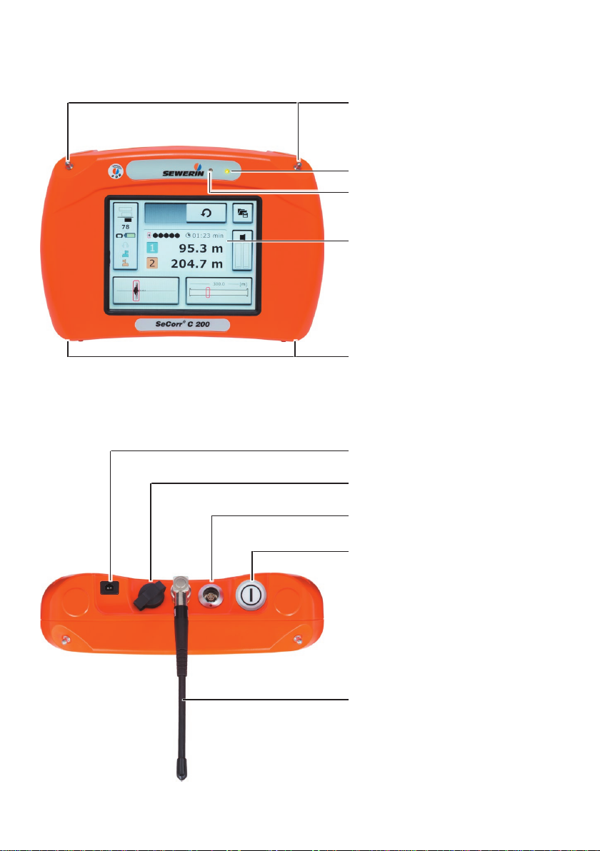
Fig. 1: C 200 receiver without aerial, front
Connectors
LED
Light sensor
Touch screen
Connectors
Charging socket
USB port
Fig. 2: C 200 receiver, top view
Microphone socket
ON/OFF key
Aerial
Page 3

RT 200 transmitter
Aerial with knob and ag
Charging socket
Fig. 3: Transmitter 1 with blue ag and
transmitter 2 with orange ag
Bandpass display
Filter key
Aerial connector
Fig. 4: RT 200 transmitter without aerial, top view
Fig. 5: RT 200 transmitter, back
LED
Light key
Microphone socket
Page 4

Information about this document
The warnings and notes in the document mean the following:
A
WARNING!
Risk of personal injury. Can result in serious injury or
death.
A
CAUTION!
Risk of personal injury. Could result in injury or pose a risk
to health.
NOTICE!
Risk of damage to property.
Note:
Tips and important information.
Enumerated lists (numbers, letters) are used for:
● Instructions that must be followed in a specic sequence
Bullet lists (bullet points, dashes) are used for:
● Lists
● Instructions comprising only one action
Page 5

1 Introduction .............................................................................1
1.1 Warranty ....................................................................................1
1.2 Purpose .....................................................................................2
1.3 Intended use .............................................................................2
1.4 General safety information ........................................................3
1.5 Radio communication ................................................................ 4
2 SeCorr system ......................................................................... 5
2.1 General information about the system ......................................5
2.2 System components .................................................................. 5
2.2.1 Overview ................................................................................5
2.2.2 C 200 receiver ........................................................................ 6
2.2.2.1 Setup ...................................................................................6
2.2.2.2 Carrying the system ............................................................ 8
2.2.2.3 Switching the receiver on and off ........................................ 9
2.2.2.4 Automatic power off ............................................................9
2.2.2.5 Main view .......................................................................... 10
2.2.2.6 How interference suppression works ................................ 15
2.2.3 RT 200 transmitter................................................................16
2.2.3.1 Setup .................................................................................16
2.2.3.2 Switching the transmitter on and off .................................. 18
2.2.4 Microphones ......................................................................... 18
2.2.4.1 UM 200 universal microphone ..........................................18
2.2.4.2 HY 200 hydrophone ..........................................................19
2.3 Filter options (overview) ..........................................................20
2.4 Plug connection between microphone and RT 200
transmitter ...............................................................................20
2.5 Power supply to the components ............................................ 21
3 System in use ........................................................................22
3.1 Preparing the system ..............................................................22
3.2 Measurement steps (overview) ...............................................22
3.3 Conguring the pipe sections .................................................. 22
3.3.1 Setting the number of pipe sections ..................................... 23
3.3.1.1 Adding a pipe section ........................................................ 24
3.3.1.2 Deleting a pipe section ...................................................... 24
3.3.2 Adjusting the pipe data .........................................................25
3.4 Performing a measurement ..................................................... 25
3.4.1 Starting a measurement ....................................................... 26
3.4.1.1 Starting the measurement after conguring pipe sections 26
Contents │ I
Page 6

3.4.1.2 Continuing measurement .................................................. 26
3.4.1.3 Repeating a measurement ................................................ 27
3.4.2 Stopping a measurement ..................................................... 27
3.4.3 Saving a measurement ........................................................27
3.4.3.1 Loading a saved measurement ......................................... 28
3.4.3.2 Deleting a saved measurement ........................................30
3.5 Optimising the correlation result using lters ..........................31
3.5.1 Filter menu (overview) ..........................................................32
3.5.1.1 Frequency graph ............................................................... 33
3.5.1.2 Correlation curve ............................................................... 34
3.5.1.3 Quality of peak .................................................................. 34
3.5.2 Selecting and adjusting lters ..............................................35
3.5.2.1 Selecting automatically calculated lters...........................35
3.5.2.2 Manually adjusting lters ................................................... 36
3.5.2.3 Applying the lters (exiting the Filter menu) ...................... 37
3.6 Plausibility check (moving the marker) .................................... 38
3.7 Listening to noises ..................................................................38
3.7.1 Information about the radio connection during listening .......38
3.7.2 Transmitter menu (overview)................................................39
3.7.3 Adjusting the volume ............................................................ 40
3.7.4 Selecting a transmitter .........................................................41
3.8 Microphone function for acoustic leak detection .....................42
3.8.1 Microphone menu (overview) ............................................... 42
3.8.2 Performing a noise measurement ........................................ 44
4 Settings ..................................................................................45
4.1 Overview .................................................................................45
4.2 Setting options ........................................................................45
4.2.1 Selecting ..............................................................................46
4.2.2 Enabling/disabling ................................................................ 46
4.2.3 Setting a value .....................................................................46
4.3 Settings in the Measurement menu ........................................48
4.3.1 General ................................................................................49
4.3.1.1 Units ..................................................................................49
4.3.1.2 Interference suppression...................................................50
4.3.1.3 Correlation curve ............................................................... 50
4.3.1.4 Blocking lter ..................................................................... 50
4.3.2 Filter basis ............................................................................ 51
4.3.2.1 Coherence.........................................................................51
4.3.2.2 Cross spectrum ................................................................. 51
4.3.2.3 Spectrum 1 or Spectrum 2 ................................................ 52
II │ Contents
Page 7

4.3.3 Pipe data (Default) ...............................................................52
4.3.3.1 Length ...............................................................................52
4.3.3.2 Material .............................................................................52
4.3.3.3 Diameter............................................................................52
4.3.3.4 Sound velocity ................................................................... 52
4.4 Settings in the Device menu ...................................................53
4.4.1 General ................................................................................54
4.4.1.1 Switching off the device ....................................................54
4.4.1.2 Switching off the backlight .................................................54
4.4.1.3 Detect position ..................................................................55
4.4.1.4 Automatic brightness.........................................................55
4.4.1.5 Brightness .........................................................................55
4.4.2 Time/Date .............................................................................56
4.4.2.1 Time ..................................................................................56
4.4.2.2 Date...................................................................................56
4.4.3 Region ..................................................................................56
4.4.3.1 Date format .......................................................................56
4.4.3.2 Time format .......................................................................57
4.4.3.3 Language ..........................................................................57
4.4.4 Service .................................................................................57
4.4.4.1 Information ........................................................................57
4.4.4.2 Calibration ......................................................................... 57
5 Servicing ................................................................................58
5.1 Charging the batteries ............................................................. 58
5.1.1 Charging the batteries in the case .......................................58
5.1.2 Charging batteries using the AC/DC adapter or vehicle
cable .....................................................................................59
5.2 Handling faulty lithium-ion rechargeable batteries ..................60
5.2.1 Identifying faulty batteries ....................................................60
5.2.2 Removing the battery from the C 200 receiver ....................61
5.2.3 Removing the battery from the RT 200 transmitter ..............62
5.3 Calibrating the touch screen ...................................................63
5.4 Care ........................................................................................64
5.5 Maintenance ............................................................................ 64
6 Appendix ................................................................................65
6.1 Technical data .........................................................................65
6.1.1 C 200 receiver ...................................................................... 65
6.1.2 RT 200 transmitter................................................................67
6.1.3 UM 200 universal microphone .............................................69
Contents │ III
Page 8

6.1.4 HY 200 hydrophone .............................................................70
6.2 Symbols on the touch screen of the C 200 receiver ...............71
6.3 Signicance of LED signals ..................................................... 73
6.3.1 C 200 receiver ...................................................................... 73
6.3.2 RT 200 transmitter................................................................74
6.4 Troubleshooting .......................................................................75
6.5 Accessories ............................................................................. 76
6.6 Declaration of conformity ........................................................76
6.7 FCC Compliance Statements .................................................. 76
6.8 Licences in the EEA ................................................................77
6.9 Note about the rmware (open source software) .................... 78
6.10 Advice on disposal ..................................................................78
7 Index .......................................................................................79
IV │ Contents
Page 9

1 Introduction
1.1 Warranty
The following instructions must be complied with in order for any
warranty to be applicable regarding functionality and safe operation of this equipment.
● Read these operating instructions prior to operating the prod-
uct.
● Use the product only as intended.
● Repairs and maintenance must only be carried out by special-
ist technicians or other suitably trained personnel. Only spare
parts approved by Hermann Sewerin GmbH may be used
when performing repairs.
● Changes or modications to this product may only be carried
out with the approval of Hermann Sewerin GmbH.
●
Use only Hermann Sewerin GmbH accessories for the product.
Hermann Sewerin GmbH shall not be liable for damages resulting from the non-observance of this information. The warranty conditions of the General Terms and Conditions (AGB) of
Hermann Sewerin GmbH are not broadened by this information.
In addition to the warnings and other information in these Operating Instructions, always observe the generally applicable safety
and accident prevention regulations.
The manufacturer reserves the right to make technical changes.
1 Introduction │ 1
Page 10

1.2 Purpose
SeCorr is a system used for correlation.
The SeCorr system can be used for:
● Detecting leaks in water pipes
Note:
All descriptions in these operating instructions refer to the system
as delivered (factory settings). The manufacturer reserves the
right to make changes.
1.3 Intended use
The SeCorr system is intended for professional industrial and
commercial use. The appropriate specialist knowledge is required to operate the system.
Note:
If necessary, learn more about the theory before commencing
practical work with the system.
The system must only be used for the applications specied in
section 1.2.
2 │ 1 Introduction
Page 11

1.4 General safety information
This product was manufactured in keeping with all binding legal
and safety regulations. It corresponds to the state of the art and
complies with conformity requirements. The product is safe to
operate when used in accordance with the instructions provided.
However, if you handle the product improperly or not as intended,
the product may present a risk to persons and property. For this
reason, always observe the following safety information.
Risk of personal injury (health risk)
●
Handle the components carefully and safely both during transport and when working.
● Proceed with extreme caution in the vicinity of electrical lines.
Hazards for the product and other property
● Always handle the components with care.
● Do not drop the components.
● Never set the components in places where they are at risk of
falling.
● It is important that the aerials of the C 200 receiver and the
RT 200 transmitter do not get damaged.
− Never bend, kink or cut the aerial.
− Never carry the C 200 receiver by its aerial.
● Before starting work, check that the components are in good
working order. Never use damaged or faulty components.
● Ensure that no dirt or moisture can get into the ports on the
components.
● Always observe the permitted operating and storage tempera-
tures.
1 Introduction │ 3
Page 12

1.5 Radio communication
The SeCorr system uses the following data transmission technologies:
● Near-eld radio
● SDR (Sewerin Digital Radio)
Near-eld radio
The transmitter and receiver communicate by near-eld radio.
The RT 200 transmitter is classed as radio equipment according to EU Directive 2014/53/EU. It may, therefore, be subject to
some use restrictions.
Note:
Users of the SeCorr system are responsible for ensuring compliance with local country regulations regarding the registration and
use of radio equipment. This applies even if there is an explicit
licence for a country.
You can nd a list of the countries of the European Economic Area (EEA) where this equipment is licensed for use in section 6.8 on page 77.
Note:
Radio systems that use the same frequencies can interfere with
each other.
● Switch off the transmitters when not in use.
SDR radio
Receivers and wireless headphones communicate by bidirec
tional SDR (SDR: Sewerin Digital Radio). SDR is only used when
listening to noises.
For more detailed information about the special features of this
radio connection, please refer to
4 │ 1 Introduction
-
section 3.7.1 on page 38.
Page 13

2 SeCorr system
2.1 General information about the system
The SeCorr system works using the correlation method, whereby
measurements are taken at two ttings (e.g. slide gate, hydrant)
at the same time. Highly sensitive microphones record the noises
at the ttings. The two microphones are each connected to a
radio transmitter. The radio transmitters transmit the signals to a
receiver – the correlator. The correlator determines the run time
difference between the signals, i.e. the time lag between the noises reaching the two measuring points. This is then used, together
with the pipe data, by the correlator to calculate the leak position.
The advantage of the correlation method is that the leak posi-
tion is determined independently of the hearing and experience
of the user.
The system features a function which can also locate leaks
acoustically if there is no suitable technology available specically for pinpointing or prelocation.
2.2 System components
2.2.1 Overview
SeCorr is a modular system. The main components of the sys-
tems are:
● C 200 receiver (correlator)
● 2 RT 200 transmitters (1 pair)
− Transmitter 1 with blue ag
− Transmitter 2 with orange ag
● 2 microphones, e.g.:
− UM 200 universal microphone
OR
− HY 200 hydrophone
One microphone is required for each
same type of microphone must always be used for the two
transmitters.
RT 200 transmitter. The
2 SeCorr system │ 5
Page 14

● F8 wireless headphones (optional)
● AC 200 SK 4 case
The system can be transported and stored in the case. The L
AC/DC adapter can be used to recharge the batteries of the
C 200, RT 200 and F8 components simultaneously inside the
case.
Accessories can be added to the system at any time.
Note:
Information about the F8 wireless headphones can be found in
the relevant operating instructions.
2.2.2 C 200 receiver
The C 200 receiver receives data from the RT 200transmitter.
The receiver calculates the leak position from the run time difference between the signals of the two receivers.
The
C 200 receiver is also known as a correlator.
2.2.2.1 Setup
Overviews with the names of all the parts of the receiver can be
found inside the front cover (g. 1 and g. 2).
Its symmetrical housing means that it can be operated by both
right-handed and left-handed users with ease.
Touch screen
The receiver features a touch screen. Certain areas of the touch
screen are touch-sensitive. Actions are performed by touching
these areas (buttons).
All of the buttons have a thick, dark grey outline.
Only your nger or a touch pen should be used to operate the
touch screen.
●
Always touch the buttons briey without exerting too much
pressure.
6 │ 2 SeCorr system
Page 15

NOTICE! Risk of damage
The surface of the touch screen is sensitive.
● Do not use any hard or sharp objects to tap the screen.
● Protect the touch screen against aggressive substances (e.g.
acidic or abrasive detergents).
A list of symbols that might appear on the touch screen can be
found in
section 6.2 on page 71.
Light sensor
The light sensor analyses the ambient lighting conditions.
If the automatic brightness setting is enabled, the light sensor
always adjusts the brightness of the touch screen to the ambient
lighting conditions.
Information about the automatic brightness setting can be found
in
section 4.4.1.4 on page 55.
ON/OFF key
The ON/OFF key is used to switch the receiver on and off.
Information on switching on and off can be found in section 2.2.2.3
on page 9.
LED
The LED indicates the operating status.
Information about what the LED signals mean can be found in
section 6.3.1 on page 73.
Aerial
When using the receiver, the aerial must be pointing upwards
(g. 6). It can be folded down for storage in the case.
2 SeCorr system │ 7
Page 16

Fig. 6: Receiver in its normal position of use
The aerial is pointing upwards.
Ports
The receiver features the following ports:
● Charging socket
For recharging the battery.
● Microphone socket
For connecting a microphone, e.g. UM 200 universal microphone.
● USB port
The USB port is only used by SEWERIN Service staff for maintenance work.
Connectors
Carrying systems (Vario, triangle, lap belt, hand loop) can be attached to the connectors.
The connectors are parts of quick-release fasteners.
2.2.2.2 Carrying the system
The receiver is usually carried in front of the body so that the user
looks diagonally down at the touch screen.
SEWERIN recommends: Use a carrying system for locating operations. The carrying system prevents you from tiring during
work. It also reduces the possibility of radio interference. Radio interference can occur if the user accidentally covers certain
components in the receiver.
8 │ 2 SeCorr system
Page 17

2.2.2.3 Switching the receiver on and off
Switching on
● Press the on/off key until the LED turns green.
Switching off
1. Briey press the on/off key. The Switch offdialog will appear.
2. Tap Switch off device. The receiver will switch off.
2.2.2.4 Automatic power off
The power supply to the receiver is designed in such a way that
a fully charged battery will allow one full day's work without interruption. However, it is still recommended to conserve energy
whilst working.
The receiver therefore offers the following automatic power-off
options:
● Switching off the device
The receiver switches off if it is not operated for a specied
period of time. It must be switched back on again when you
want to continue work.
● Switching off the backlight
The receiver backlight switches off if it is not operated for a
specied period of time. The receiver remains switched on.
If and when the automatic power off is activated depends on the
settings (Device menu > General > Switch off device or Switch
off backlight).
2 SeCorr system │ 9
Page 18
2.2.2.5 Main view
The touch screen of the receiver displays the main view when
the system is ready for use.
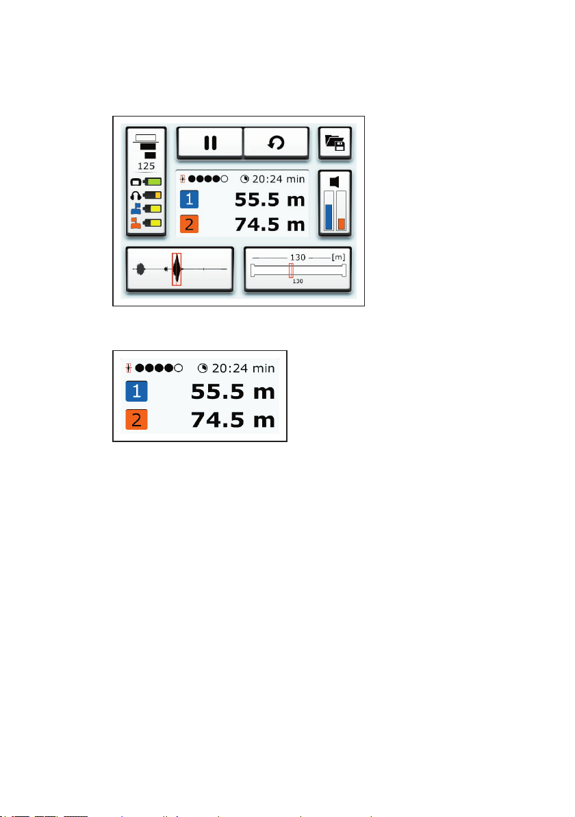
Fig. 7: Main view
Fig. 8: Results display (detail of main view)
The following is shown in the centre of the main view (g. 8):
● Leak position
Distance of leak from transmitter 1 and transmitter 2
● Quality of peak
● Duration of measurement
10 │ 2 SeCorr system
Page 19
The main view also contains the following buttons:
● Measurement
● File
● Transmitter
● Pipe sections
● Filter
● Settings
These buttons can be used to open submenus. Most of the buttons also display information. The information displayed depends
on the situation.
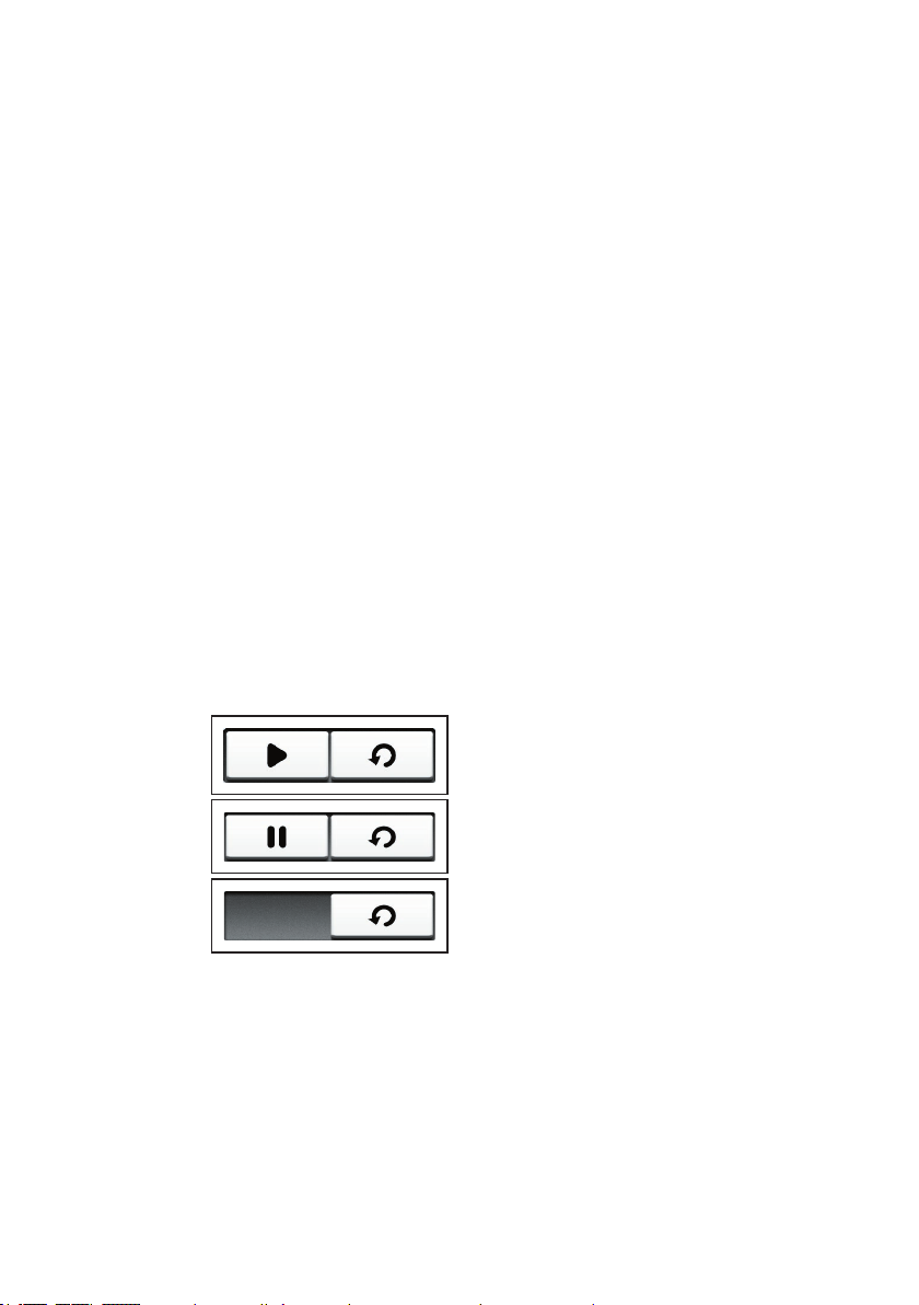
Measurement
The Measurement button is divided into different sections. The
appearance of the Measurement button depends on what the
program is doing (g. 9).
● Start measurement button
OR
Stop measurement button
● Reset button
Fig. 9: Measurement button at various stages of the program
Top image: A measurement can be started.
Centre image: A measurement can be stopped.
Bottom image: The calculation data must be reset before a meas-
urement can be started.
For more detailed information on performing measurements,
please refer to section 3.4 on page 25.
2 SeCorr system │ 11
Page 20
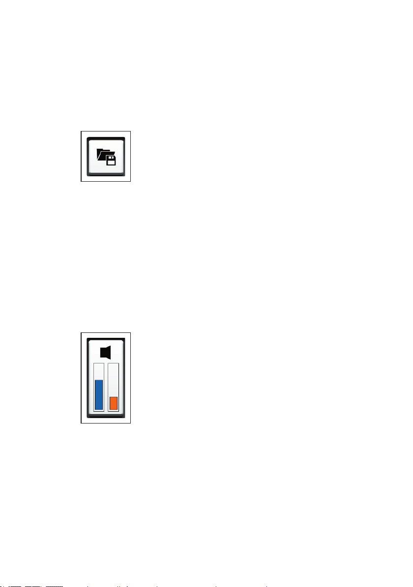
File
The File menu is opened by pressing the Filebutton. The following actions can be performed in this menu:
● Save measurement
● Load saved measurement
● Delete saved measurement
Fig. 10: File button
For information about saving, loading and deleting measurements, please refer to section 3.4.3 on page 27.
Transmitter
The Transmitter button displays the following information:
● Current noise level of the transmitters
− Left: Transmitter 1 (blue)
− Right: Transmitter 2 (orange)
Fig. 11: Transmitter button
The Transmitter menu is opened by pressing the Transmitter
button. The following settings can be made in this menu:
● Transmitters from which noises can be heard through head-
phones
● Volume of noise on headphones
Information about the two transmitters is also displayed.
12 │ 2 SeCorr system
Page 21
For more detailed information about the Transmitter menu and
listening to noises, please refer to section 3.7 on page 38.
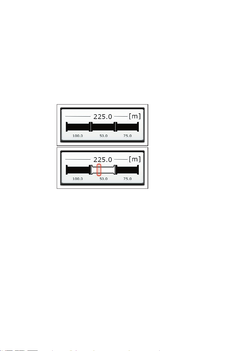
Pipe sections
The Pipe sections button displays the following information:
● Total length of measuring section
● Number and length of pipe sections
● Marker
Indicates the leak position in the pipe section concerned.
Fig. 12: Pipe sections button, here: Measuring section with three pipe
sections
Top image: Before starting a measurement.
Bottom image: After starting/stopping a measurement
The Pipe sections menu is opened by pressing the Pipe sec-
tions button. The following settings can be made in this menu:
● Number of pipe sections in a measuring section
● Pipe data for every pipe section
− Material
− Diameter
− Length
− Sound velocity
For more detailed information about conguring the pipe sections, please refer to section 3.3 on page 22.
2 SeCorr system │ 13
Page 22
Filter
The Filter button displays the following information:
● Correlation curve
● Marker
Corresponds to the leak position.
Fig. 13: Filter button
The Filter menu is opened using the Filter button. This menu
allows you to optimise the correlation result using lters.
For more detailed information on lters, please refer to sec-
tion 3.5 on page 31.
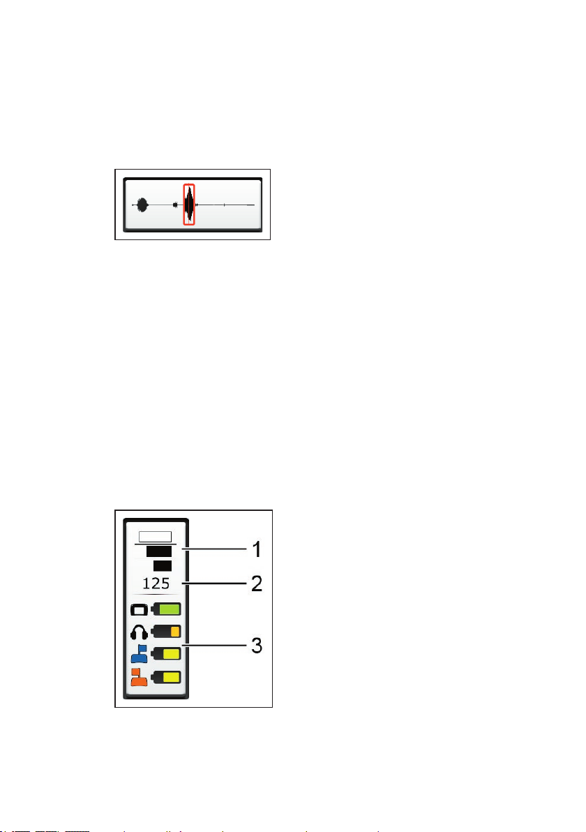
Settings
The Settings button displays the following information:
● Interference suppression setting
● Number of calculations
● Connected components and information about the charge of
the relevant batteries
Fig. 14: Settings button
14 │ 2 SeCorr system
1 Interference suppression, 2 Calculations
3 Components and charge of relevant batteries
Page 23
The Settings menu is opened using the Settings button. The
following settings can be adjusted in this menu:
● Measurement
● Device
For more detailed information on the Settings menu, please refer
to section 4 on page 45.
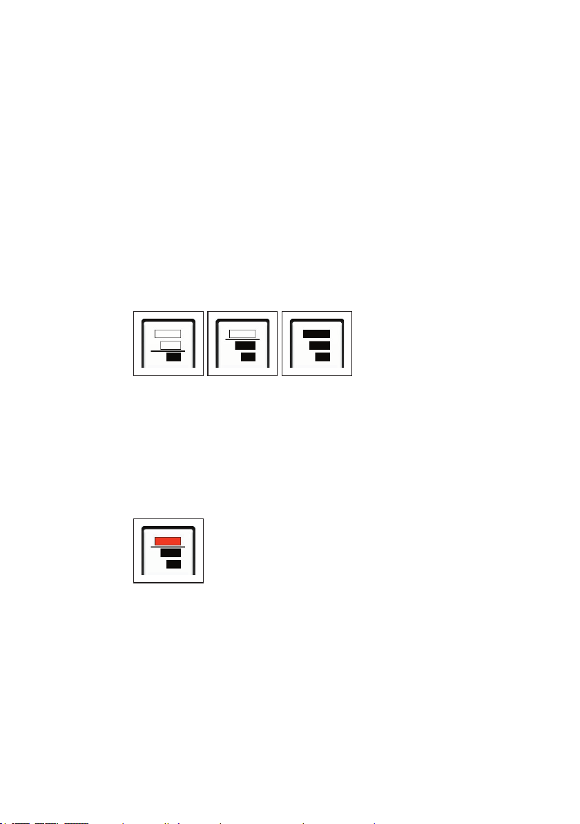
2.2.2.6 How interference suppression works
The interference suppression function allows you to exclude noises from the correlation that may have a negative effect on the
result (e.g. sound interference from passing vehicles).
How interference suppression works depends on the settings
(Measurement menu > General).
Fig. 15: Interference suppression (detail of Settings button)
Left image: High interference suppression
Centre image: Low interference suppression
Right image: Interference suppression off
Whenever interference suppression is active during a measurement, the interference suppression symbol turns red on the Set-
tings button.
Fig. 16: Interference suppression active, here: with low interference sup-
pression setting
2 SeCorr system │ 15
Page 24

2.2.3 RT 200 transmitter
The RT 200 transmitters send the measurement data from the
microphones to the C 200 receiver. The transmitters are always
used in pairs.
The two transmitters are marked with a number and a colour to
make them distinct.
● Transmitter 1 with blue ag
● Transmitter 2 with orange ag
Note:
C 200 receiver uses the same number and colour assign-
The
ment, e.g. when displaying results.
2.2.3.1 Setup
Lists with the names of all the parts of the transmitter can be
found inside the front cover (g. 3 to g. 5).
Ports
The transmitter features the following ports:
● Charging socket
For recharging the battery.
● Microphone socket
For connecting a microphone.
Filter key
Note:
The SeCorr system has lter options for various purposes. An
overview of these can be found in
The bandpass can be adjusted using the lter key. A bandpass is
a lter that only allows signals through from a certain frequency
range.
16 │ 2 SeCorr system
section 2.3 on page 20.
Page 25

This function can be used to adjust the noise transmission to the
f
f
f
current situation. For example, when performing correlation on
plastic pipes, the quality of the measurement can be improved if
necessary using the low pass setting.
The options are:
● Low pass
Allows all signals below a limit frequency through. Blocks any signals
above the limit frequency.
● Default
● High pass
Allows all signals through.
Allows all signals above a limit frequency through. Blocks signals below
the limit frequency.
There is an LED next to each symbol. The LED of the set bandpass turns green.
The RT 200 always switches to the Default setting when switched
on.
Light key
The light key is used to switch the light source of the
UM 200
universal microphone on and off.
LED
The LED indicates the operating status.
Information about what the LED signals mean can be found in
section 6.3.2 on page 74.
Aerial
There is a knob at the top end of the aerial for convenient carrying of the transmitter.
2 SeCorr system │ 17
Page 26

2.2.3.2 Switching the transmitter on and off
Switching on
The transmitter automatically switches on as soon as a microphone is connected.
Switching off
The transmitter automatically switches off as soon as the microphone is disconnected from the transmitter.
For more detailed information about the plug connection between
the microphone and the transmitter, please refer to section 2.4
on page 20.
2.2.4 Microphones
The microphones record noises at the measurement locations.
This data is then sent to the transmitters via cable.
The system can be used with different microphones. One microphone is required for each
RT 200 transmitter. The same type of
microphone must always be used for the two transmitters.
2.2.4.1 UM 200 universal microphone
The UM 200 is a highly sensitive microphone for picking up struc-
ture-borne noise.
NOTICE!
UM 200 features a component which is susceptible to dam-
The
age from adverse forces.
● Never drop the microphone.
Accessories can be attached to the UM 200, e.g. a contact adapter. The right accessories can be used to secure the microphone
at various measurement locations.
18 │ 2 SeCorr system
Page 27

CAUTION!
A
Note:
The contact adapter comes with a protective screen,
The microphone features a light source which can be used to illuminate the measurement location (torch function).
A
Danger when using the contact adapter
The contact adapter contains a strong magnet.
● Keep the contact adapter away from magnetic storage
media (e.g. hard drives, credit cards) and medical devices (e.g. pacemakers, insulin pumps).
● which should be removed before rst use.
CAUTION! Risk of glare
The light source comprises two powerful LEDs.
● Do not look directly into the light.
● Never shine the light into the eyes of another person.
2.2.4.2 HY 200 hydrophone
The HY 200 hydrophone records noises directly from the water
column.
CAUTION! Risk of contamination
A
2 SeCorr system │ 19
The HY 200 is designed for use in drinking water net-
works.
● Always disinfect the HY 200 before use.
Page 28

2.3 Filter options (overview)
Filters can be used both on the transmitter and the receiver. Filters are used for different purposes.
● RT 200 transmitter
− The bandpass can be adjusted using the lter key. This set-
ting determines the extent to which incoming signals are
sent to the receiver (section 2.2.3.1).
● C 200 receiver
−
The correlation result can be optimised using lters (section 3.5).
− A blocking lter can be used to minimise the effects of cur-
rent-carrying electrical lines on the noise (section 4.3.1.4).
−
Date lters can be set in the list of saved measurements
when searching for specic measurements (section 3.4.3.1).
2.4 Plug connection between microphone and RT 200 transmitter
The plug connection is coded. For clarity, the following are each
marked with a red dot:
● Plug on microphone cable
● Microphone socket on RT 200 transmitter
Connecting the microphone
●
Align the two red dots with each other. The plug can be inserted
into the microphone socket.
Disconnecting
● Pull back the cover on the microphone plug. This will release
the connection. The microphone cable can now be removed.
20 │ 2 SeCorr system
Page 29

2.5 Power supply to the components
The following components are powered by a special, inbuilt rechargeable lithium-ion battery.
● C 200 receiver
● RT 200 transmitter
The F8 wireless headphones come with a rechargeable NiMh
battery.
For information on charging the batteries, please refer to section 5.1 on page 58.
NOTICE! Risk of damage when changing lithium-ion batteries
The battery compartments of the components contain parts that
could get damaged when the batteries are being replaced.
●
Only SEWERIN service personnel or other authorised specialists may replace rechargeable lithium-ion batteries.
WARNING! Risk of explosion due to short circuit
A
Faulty lithium-ion batteries can explode due to an internal
short circuit.
● Do not send components with a faulty lithium-ion bat-
tery.
2 SeCorr system │ 21
Page 30

3 System in use
3.1 Preparing the system
Two suitable measurement locations must be found depending
on conditions on the ground. Suitable measurement locations
include, for example, ttings or the pipe itself.
1. Attach a microphone to each of the measurement locations.
− The same microphone type must be used at the two meas-
urement locations.
2.
Connect each of the microphones to an RT 200. The RT 200s
will switch on automatically.
3. Switch on the C 200 receiver. The system is ready for use.
3.2 Measurement steps (overview)
Once the system has been prepared, location can begin.
A measurement comprises the following steps:
1. Conguring the pipe sections (section 3.3 on page 22)
2. Starting a measurement (section 3.4.1 on page 26)
3. Stopping a measurement (section 3.4.2 on page 27)
4. Selecting and adjusting lters
(optional) (section 3.5.2 on page 35)
5. Saving a measurement
(optional) (section 3.4.3 on page 27)
3.3 Conguring the pipe sections
A measuring section can comprise one or more pipe sections.
Each pipe section is characterised by its pipe data. New pipe
sections are automatically assigned values from the Pipe data
(Default).
22 │ 3 System in use
Page 31

Note:
The quality of the correlation result depends greatly on the con-
guration of the pipe sections.
●
Make sure you congure the pipe sections completely and cor-
rectly in accordance with the conditions on the ground.
● Adjust the settings before starting the measurement.
Any changes made after the start of a measurement will mean
that it will not be possible to continue the measurement afterwards.
The main view is open.
1. Tap the Pipe sections button. The Pipe sections menu will
appear.
Fig. 17: Pipe sections menu
Top: Diagram of pipe sections, here: measuring section
with two pipe sections, 2nd pipe section selected
(highlighted blue)
Top right: Add button
Centre: Pipe data from the selected pipe section
2. Set the number of pipe sections (section 3.3.1).
3. Adjust the pipe data for every pipe section (section 3.3.2).
3.3.1 Setting the number of pipe sections
A measuring section consists of:
● at least one pipe section
● a maximum of ve pipe sections
3 System in use │ 23
Page 32

3.3.1.1 Adding a pipe section
The rst pipe section is set on transmitter 1.
● Up to four more pipe sections can be added between the rst
pipe section and transmitter 2.
● New pipe sections are added to the right of the selected pipe
section.
The Pipe sections menu is open.
1. Tap on the pipe section beside which you want to add a new
pipe section. The pipe section will be highlighted in blue.
2. Tap on the Add button. A new pipe section will be added.
Note:
Adjust the pipe data for the new pipe section (
3.
Apply the settings by pressing Conrm. The receiver will
switch back to the main view.
3.3.1.2 Deleting a pipe section
Pipe sections can be deleted.
The last remaining pipe section cannot be deleted. The pipe
data for it, however, can be reset to the default values by going
through the deletion process.
section 3.3.2).
The Pipe sections menu is open.
1. Tap the pipe section to be deleted. The pipe section will be
highlighted in blue.
2. Tap the selected pipe section again. The pipe section will be
deleted without any further conrmation prompt.
3.
Apply the settings by pressing Conrm. The receiver will
switch back to the main view.
24 │ 3 System in use
Page 33

3.3.2 Adjusting the pipe data
Pipe sections are characterised by the following features:
● Length of pipe
● Diameter of pipe
● Pipe material
● Sound velocity in the pipe section
Adjoining pipe sections in a measuring section can have different pipe data.
New pipe sections are automatically assigned values from the
Pipe data (Default). The values must then be adjusted according
to the conditions on the ground.
For more detailed information about the selection options and
value ranges, please refer to section 4.3.3 on page 52.
The Pipe sectionsmenu is open.
1.
Tap the pipe section for which you want to adjust the pipe
data. The pipe section will be highlighted in blue.
2. Adjust the pipe data.
3.
Apply the settings by pressing Conrm. The receiver will
switch back to the main view.
3.4 Performing a measurement
Each measurement must be started manually and stopped at a
suitable time.
Once a measurement has been stopped, it can be saved, continued or repeated.
3 System in use │ 25
Page 34

3.4.1 Starting a measurement
Note:
The quality of the correlation result also depends on the general
noise level at the start of a measurement.
● Wherever possible, try to start a measurement when there is
no loud sound interference in the background (e.g. no passing
vehicles, extraction from house connections).
The main view is open. The Start measurement button is vis-
ible (g. 9, image above).
●
Tap the Start measurement button when the general noise
level is suitable. The measurement will start. The Stop meas-
urement button will appear.
3.4.1.1 Starting the measurement after conguring pipe sections
Once the pipe sections have been congured, the calculation
data must be reset before a new measurement can be started.
The main view is open. The Start measurement button is not
visible (g. 9, image below).
1.
Tap the Reset button. The Start measurement button will
appear.
2. Tap the Start measurement button when the general noise
level is suitable. The measurement will start. The Stop meas-
urement button will appear.
3.4.1.2 Continuing measurement
Measurements can be continued under the following conditions:
● The measurement has been stopped.
● The pipe sections have not been changed.
● The calculation data has not been reset.
To continue the measurement, it must be restarted.
26 │ 3 System in use
Page 35

●
Tap the Start measurement button when the general noise
level is suitable. The measurement will start. The Stop meas-
urement button will appear.
3.4.1.3 Repeating a measurement
Measurements can be repeated under the following conditions:
● The measurement has been stopped.
● The pipe sections have not been changed.
To repeat a measurement, it must be restarted.
1.
Tap the Reset button. The Start measurement button will
appear.
2. Tap the Start measurement button when the general noise
level is suitable. The measurement will start. The Stop meas-
urement button will appear.
3.4.2 Stopping a measurement
Ongoing measurements can be stopped at any time.
In order to achieve a reliable result, SEWERIN recommends: Not
stopping the measurement until the marker, leak position and
quality of the peak stop changing.
The main view is open. A measurement is ongoing.
●
Tap the Stop measurement button. The measurement will
stop. The Start measurement button will appear.
Stopped measurements can be saved or continued.
3.4.3 Saving a measurement
Measurements can be saved. Approximately 70 measurements
can be saved.
A message will appear when the memory is full. Measurements
can be deleted from the memory to free up space. For information about deleting saved measurements, please refer to section 3.4.3.2 on page 30.
Saved measurements are indicated by:
● Date (day and time measurement was saved)
● optional: Remark
3 System in use │ 27
Page 36

The main view is open. The measurement was stopped
1. Tap the File button. The File menu appears.
2. Tap the Save button. The Comment menu appears.
3. Measurements can be saved with or without additional information.
● Tap Conrm to save the measurement without additional
information.
OR
a) Enter a comment using the virtual keyboard.
The comment can be up to a maximum of 25 characters
long.
b) Tap Conrm to save the measurement with additional in-
formation.
The receiver will switch back to the main view.
3.4.3.1 Loading a saved measurement
Saved measurements can be loaded from the memory. Information about the measurement can also be displayed.
Note:
Only one measurement can be loaded at a time.
The main view is open.
1. Tap the File button. The File menu appears.
2. Tap the Load button. This Load menu will appear.
28 │ 3 System in use
Page 37

Fig. 18: Load menu
Top left: Filter by date button
Centre: List of saved measurements
3. Tap the relevant measurement in the list. The measurement
will immediately appear in the main view.
Searching for saved measurements
Date lters can be set in the list of saved measurements to search
for specic measurements.
The following date lters are available:
● Year
● Year and month
The Load menu is open.
1. Tap the Filter by date button on the top left. The Filter by
date menu will appear.
2. Set the values for the search.
− Left-hand eld: Year, right-hand eld: Month
− Any means that no date lter will be set.
−
Only values that have been saved for the data are available
for the search.
Example:
Measurements were saved in 2013 and 2015. No measure-
ments were saved in 2014. The lter criteria available for
selection are: Any, 2013, 2015.
3.
Apply the lters by pressing Conrm. The receiver will switch
back to the Load menu.
3 System in use │ 29
Page 38

The list will show all the measurements that match the search
criteria. The date lter settings are displayed on the Filter by
date button.
Fig. 19: Filter by date button
Left image: No date lter set
Right image: Date lter set (year: 2015, month: 01 January)
3.4.3.2 Deleting a saved measurement
Saved measurements can be deleted individually. To do this delete mode needs to be enabled.
NOTICE! Risk of data loss
In delete mode, measurements are deleted immediately without
a conrmation prompt.
● Work with extreme care in delete mode.
The main view is open.
1. Tap the File button. The Archive menu will appear.
2. Tap the Load button. This Load menu will appear.
3.
Tap the Clear button. Delete mode is enabled. The dot on
the Clear button turns red. The measurements in the list appear in red.
4.
Tap the measurement you want to delete in the list. The measurement will be deleted immediately without further prompting.
5. Finally, disable delete mode.
30 │ 3 System in use
Page 39

● To do this, tap the Clear button again. Delete mode is disa-
bled. The dot on the Clear button turns grey again. The
measurements in the list appear in black.
OR
● Tap Back.
3.5 Optimising the correlation result using lters
Note:
The SeCorr system has lter options for various purposes. An
overview of these can be found in
section 2.3 on page 20.
Filters can help optimise the correlation result and thus locate
leaks more reliably. Filters are set in the frequency graph.
A well-applied lter will have the following effect on the correlation curve:
●
Peaks will be displayed in higher quality, i.e. sharper, with
steeper sides, etc.
● The peak of a potential leak noise will be accentuated com-
pared to other noises (e.g. sound interference).
Aim of optimisation
The aim is to obtain the highest quality peak possible in the correlation curve.
3 System in use │ 31
Page 40

3.5.1 Filter menu (overview)
The Filter menu displays the frequencies, correlation curve and
the result of the measurement as a graph.
Fig. 20: Filter menu
Top: Frequency graph
Centre: Correlation curve
Bottom: Result of measurement and quality of peak
Right (top to bottom): Lower lter limit, upper lter limit,
current lter buttons
Available lters
Various lters can be applied.
The options are:
● Auto 1 Automatically calculated lter 1
● Auto 2 Automatically calculated lter 2
● Manual Manually set lter
The symbol of the active lter is displayed on the Current l-
terbutton.
Manually set lters are saved with a measurement.
32 │ 3 System in use
Page 41

3.5.1.1 Frequency graph
The receiver displays the spectra of the noises in the frequency
graph.
Fig. 21: Frequency graph
1 Lower stopband, 2 Lower lter limit, 3 Graph of functions,
4 Passband, 5 Upper lter limit, 6 Upper stopband,
7 Frequency axis
In the settings you can specify whether to display one or two
functions (Measurement menu > Filter basis).
If two functions are displayed:
● Areas in which the two functions overlap are shown in black.
● If the values of one function are lower than the values of the
other function across the whole frequency range, you will only
be able to see the function with the higher values and the
overlap.
One lter is always set in the frequency graph. This lter can be
changed.
● The lter currently applied will be shown on the Current lter
button.
●
The values of the lter limits will be specied on the Lower
lter limit and Upper lter limit buttons.
Dashes will be shown instead of digits if an automatic lter calculates the entire frequency range as the passband.
3 System in use │ 33
Page 42

3.5.1.2 Correlation curve
The run time difference between the signals of the two transmitters is displayed in the correlation curve.
Fig. 22: Correlation curve with marker (red rectangle)
The area around the highest peak of the curve is marked with a
red rectangle. This marker indicates the calculated leak position.
If a correlation curve shows several signicant peaks, a plausibility check should be carried out (section 3.6).
3.5.1.3 Quality of peak
The sharper or clearer the peak, the better the quality. The quality
can be improved by setting lters.
The quality of a peak is rated by dots. The more black dots, the
higher the quality.
Fig. 23: Quality of peak
Left image: Very high quality
Right image: Poor quality
Note:
The quality of a peak does not correlate to the accuracy of the
calculated leak position.
34 │ 3 System in use
Page 43

3.5.2 Selecting and adjusting lters
One lter is always set in the frequency graph when the Filter
menu is opened. Whether an automatically calculated lter or a
manually set lter is applied rst depends on the starting point.
Once the menu has been opened, you can switch between lters.
Automatic lters are always recalculated when the Filter menu
is opened.
Opening the lter menu
The main view is open.
● Tap the Filter button. Wait until the Filter menu appears.
Note:
Any ongoing measurements will be stopped when the Filter
menu is opened.
3.5.2.1 Selecting automatically calculated lters
Note:
Filters
Auto 1 and Auto 2 are identical if the calculation algo-
rithms on which they are based do not detect any differences.
The Filter menu is open.
●
Repeatedly tap the Current lter button. If the Auto 1 or
Auto 2 symbol appears, automatically calculated lter 1 or 2
will be applied.
3 System in use │ 35
Page 44

3.5.2.2 Manually adjusting lters
There are two ways of manually adjusting the lter limits:
● Quick adjustment
● Exact adjustment
Performing a quick lter adjustment
A quick adjustment involves resetting both lter limits.
The Filter menu is open.
1. Tap the frequency graph (g. 21)
− as accurately as possible.
The Filter
menu will change its appearance (g. 24). The rst
lter limit is set.
Fig. 24: Filter menu – quick adjustment
2. Tap the frequency graph a second time.
The Filter
second lter limit is set. The Manual symbol is visible on the
Current lter button.
Performing an exact lter adjustment
When performing an exact adjustment, the upper and lower lter
limits are set independently of each other. The lter limits can be
moved in very small increments.
36 │ 3 System in use
− The higher of the two tapped frequency values will be as-
signed to the upper lter limit.
menu will return to its default view (g. 20). The
Page 45

The Filter menu is open.
1. Tap either the Lower lter limit or the Upper lter limit but-
ton.
The Filter menu will change its appearance (g. 25). The
stopband of the lter limit that can be adjusted is shown in
orange.
Fig. 25: Filter menu – exact lter adjustment, here: adjusting the
lower lter limit
2. Reset the selected lter limit.
− Tap the frequency graph to roughly set the lter limit.
− To set the lter limit exactly, keep tapping one of the Move
buttons until the desired position has been reached.
Ensure that the upper and lower lter limits do not overlap.
3. Apply the lter limit by tapping Conrm. The Filter menu will
appear again in its default view (g. 20). The Manual symbol
is visible on the Current lter button.
4. If necessary, repeat all the steps for the other lter limit.
3.5.2.3 Applying the lters (exiting the Filter menu)
The settings can be applied once the lter limits have been adjusted.
The Filter menu is open.
● Tap Back. The lter settings will now be applied. The receiver
will switch back to the main view.
3 System in use │ 37
Page 46

3.6 Plausibility check (moving the marker)
The correlator cannot determine whether there is an actual leak
at a calculated position or whether the noise is interference (e.g.
open house connection).
This can pose a problem if the correlation curve shows more than
one signicant peak. In such cases, we recommend checking the
plausibility of the correlation result.
The Filter menu is open.
1. Move the marker in the correlation curve to another peak.
− To do this, tap the relevant position in the curve.
2. Read off the recalculated leak position.
3. Check the conditions on the ground.
− Is there another noise source at the calculated position?
3.7 Listening to noises
Note:
F8 wireless headphones are required for listening to noises.
3.7.1 Information about the radio connection during listening
The
C 200 receiver and F8 wireless headphones communicate
by bidirectional SDR (SDR: Sewerin Digital Radio).
SDR transmits uncompressed signals in real time. Radio interference can, therefore, cause a short clicking noise in the headphones.
SDR uses the same frequency ranges as, for example, WLAN
or Bluetooth. In rare cases, SDR can, therefore, be affected by
other radio connections.
These effects can be minimised by the following measures:
● Avoid drops in the SDR radio connection caused by obstruc-
tions, e.g. your own body. Carry the receiver in such a way
that the transmission path to the headphones is not obscured.
38 │ 3 System in use
Page 47

●
If you are carrying electronic devices that use WLAN and Bluetooth directly on your body: Disable the WLAN and Bluetooth
function if necessary.
3.7.2 Transmitter menu (overview)
The Transmitter menu displays information about the transmitters connected by radio.
The following noise settings can be adjusted:
● Volume on the headphones
● Transmitter selection
The microphone function can be opened if a microphone is connected to the receiver.
Fig. 26: Transmitter menu without a connected transmitter
Fig. 27: Transmitter menu with connected transmitters
Top: Volume
Centre: Transmitter selection
Left/right: Information about transmitter 1/2
3 System in use │ 39
Page 48

Information about the transmitters
The following information appears as soon as an
mitter is connected:
● Strength of radio signal at receiver
● Current noise level at transmitter
● Battery charge
● Bandpass setting
Information about the GPS position of the transmitter is not currently in use for technical reasons.
Fig. 28: Information about the transmitter, here: Transmitter 1
From left to right: Radio signal, noise level, rechargeable battery,
bandpass
Note:
The information is not constantly updated as radio transmission
of the noise takes precedence. It can sometimes take up to 20s
for changes to be displayed.
RT 200 trans-
3.7.3 Adjusting the volume
The volume determines how loudly the noises are played back
through the headphones.
CAUTION! Health hazard
A
40 │ 3 System in use
Excessive noise can cause damage to hearing and result
in irreversible health problems.
● Always adjust the volume to the current situation.
● Choose as low a volume as possible.
Page 49

The main view is open.
1. Tap the Transmitter button. The Transmitter menu will appear.
2. Adjust the volume by tapping either:
− the volume symbols
− in the area between the two volume symbols
Fig. 29: Adjusting the volume
3.
Apply the settings by pressing Conrm. The receiver will
switch back to the main view.
The settings are stored until they are next adjusted.
3.7.4 Selecting a transmitter
The noises from the two measuring points can be listened to
together or separately.
The options are:
● Noises from transmitters 1 and 2
● Noises from transmitter 1
● Noises from transmitter 2
● No noise
3 System in use │ 41
Page 50

The main view is open.
1. Tap the Transmitter button. The Transmitter menu will appear.
2. Tap the relevant transmitter selection. The setting is applied
immediately.
The setting is stored until it is next adjusted.
3.8 Microphone function for acoustic leak detection
The microphone function is an extra function on the
ceiver.
The microphone function can be used to listen to noises directly
at a measurement location. It can be used when there is no suitable technology available specically for pinpointing or prelocation.
Note:
The microphone function cannot be used for correlation.
The following system components are required for acoustic leak
detection:
● C 200 receiver
● Microphone, e.g. UM 200 universal microphone
● F8 wireless headphones
C 200 re-
3.8.1 Microphone menu (overview)
A measurement to listen to noises can be performed in the Microphone menu. The results of the measurement are displayed
in a graph and as numerical values.
Note:
The Microphone menu can only be opened when a microphone
is connected to the receiver.
42 │ 3 System in use
Page 51

Fig. 30: Microphone menu
Fig. 31: Display of measurement values (detail of Microphone menu)
1 Current minimum noise level
2 Current noise level
3 Previous minimum noise level
The following measurement values are displayed (g. 31):
● Current noise level
● Current minimum noise level
● Previous minimum noise level
The Microphone menu also contains the following buttons:
● Volume
● Light
● Listen to microphone
● Turn off noise
The volume for the microphone function (Microphone menu) is
independent of the volume for listening to noises (Transmitter
3 System in use │ 43
Page 52

menu). The volume must be set separately in the two menus. The
setting procedure is identical.
The Light button can be used to switch the microphone’s light
source on and off.
3.8.2 Performing a noise measurement
The current noise level is always displayed in the Microphone
menu. However, the noises can only be heard once a measurement has started.
The receiver is switched on. The main view is open.
1.
Connect a microphone (e.g. UM 200) to the microphone socket on the receiver.
2. Attach the microphone to a suitable measurement location.
3. Tap the Transmitter button. The Transmitter menu will appear. The Microphone button can be seen at the bottom right.
Which microphone symbol appears on the Microphone but-
ton depends on the microphone connected.
4. Tap the Microphone button. The Microphone menu will appear.
5.
Tap the Listen to microphone button to start a measurement.
6. Adjust the volume to the current situation.
− Proceed as explained in section 3.7.3 on page 40.
−
Please note the health hazard warning in the same section.
7. Tap the Switch noise off button when you want to stop the
measurement.
Exiting the Microphone menu
●
To return to the Transmitter menu, tap the Transmitter button.
● To return to the main view, tap Back.
44 │ 3 System in use
Page 53

4 Settings
4.1 Overview
All settings are managed using the
can be changed at any time. The following menus are available:
● Measurement
● Device
4.2 Setting options
The settings in the Measurement and Device menus are implemented as follows:
● Select
● Enable/disable
● Set value
C 200 receiver. The settings
Fig. 32: Menu (sample diagram)
Top: Menu item with selected settings
Below: Menu items with enable/disable settings
Bottom: Menu items with set values
Menu items in which settings can be selected or values adjusted
are indicated by the next symbol.
Menu items in which settings can be enabled/disabled are indicated by a radio button (dot).
4 Settings │ 45
Page 54

4.2.1 Selecting
Fig. 33: Selecting a setting (sample diagram)
Top: Setting selected
Bottom: Setting not selected
Selected settings are indicated by the tick symbol.
1. In one of the menus, tap on the menu item for which you wish
to change the setting.
A sub-menu will appear.
2. Tap the relevant setting.
The setting is applied immediately without further conrma-
tion. The receiver goes back up a menu level.
The selected setting is displayed in the higher menu level.
4.2.2 Enabling/disabling
Fig. 34: Enable/disable setting (sample diagram)
Enabled settings are indicated by a green option button. Disabled
settings have a grey option button.
● In the menu tap on the menu item to be enabled/disabled.
The setting is applied and displayed immediately without a
conrmation prompt.
4.2.3 Setting a value
Values are set either via a picklist or a numeric keypad.
46 │ 4 Settings
Top: Setting enabled
Bottom: Setting disabled
Page 55

Picklist
Fig. 35: Picklist
Values are set using the arrow keys.
1. Tap on an arrow key.
− The up key increases the value.
− The down key decreases the value.
2. Apply the settings by pressing Conrm.
The receiver goes back up a menu level.
Numeric keypad
Fig. 36: Numeric keypad
1. Tap the relevant number keys. The selected numbers will be
displayed via the numeric keypad.
2. Apply the value by pressing Conrm.
The value is rounded up or down if it is outside the value range
or has an invalid number of decimal places.
The receiver switches back to the parent menu.
4 Settings │ 47
Page 56

4.3 Settings in the Measurement menu
General
Units > Metric
Anglo-American
Interference suppression > high
low
Off
Correlation curve > Positive
Positive & negative
Blocking filter > 60 Hz
50 Hz
Off
Filter basis
Coherence > blue
red
Off
Cross spectrum > blue
red
Off
Spectrum 1 > blue
red
Off
Spectrum 2 > blue
red
Off
Pipe data (Default)
Length > …
Material > AC
Copper
…
Diameter > …
Sound velocity > …
The settings in the Measurement menu apply to the measurements.
Fig. 37: Measurement menu
48 │ 4 Settings
Page 57

The main view is open.
1. Tap the Settings button. The Settings menu appears.
2. Tap the Measurement button. The Measurement menu ap-
pears.
3. Adjust the settings as required.
The Measurement menu is divided into three views General,
Filter basis and Pipe data (Default).
Switch between the views using the Scroll buttons.
The settings options are explained in the next sections.
4. To nish, tap the Back button. The Settings menu appears.
5. Tap Back again to return to the main view.
4.3.1 General
4.3.1.1 Units
Different units can be used for specifying the pipe data.
The options are:
● Metric
Length specied in metres (m) and diameter specied in mil-
limetres (mm).
● Anglo-American
Length specied in feet (ft.) and diameter specied in inches
(in.).
4 Settings │ 49
Page 58

4.3.1.2 Interference suppression
Excessive noise can be suppressed to varying degrees.
The options are:
● High
Interference suppression is enabled and has a signicant inuence. Some slightly quieter noises may be excluded from
the correlation.
● Low
Interference suppression is enabled. Only very loud noises are
excluded from the correlation.
● Off
Interference suppression is disabled.
SEWERIN recommends: Use the low setting when enabling the
interference suppression.
4.3.1.3 Correlation curve
The correlation curve can be displayed in different ways.
The options are:
● Positive
Displays the magnitude of the positive and negative values.
The correlation curve is above the x-axis.
● Positive & negative
Displays both positive and negative values. The correlation
curve oscillates around the x-axis.
4.3.1.4 Blocking lter
The blocking lter is an electronic lter which lters out the mains
frequency of the power supply. This minimises the impact of current-carrying electrical lines on the noise.
The options are:
● 60 Hz | 50 Hz
Mains frequency that can be selected.
● Off
The blocking lter is disabled.
50 │ 4 Settings
Page 59

4.3.2 Filter basis
The noises can be displayed as a graph based on different functions in the Filter menu.
The options are:
● Coherence
● Cross spectrum
● Spectrum 1
● Spectrum 2
Up to a maximum of two functions can be displayed at the same
time.
4.3.2.1 Coherence
Coherence of noises transmitted by transmitters 1 and 2 to the
receiver.
The options are:
● blue | red
Colour that can be selected for the graph.
● Off
The function is not displayed.
4.3.2.2 Cross spectrum
Cross power spectrum of noises transmitted from transmitters 1
and 2 to the receiver.
The options are:
● blue | red
Colour that can be selected for the graph.
● Off
The function is not displayed.
4 Settings │ 51
Page 60

4.3.2.3 Spectrum 1 or Spectrum 2
Auto-power spectrum of the noises transmitted from transmitter
1 or transmitter 2 to the receiver.
The options are:
● blue | red
Colour that can be selected for the graph.
● Off
The function is not displayed.
4.3.3 Pipe data (Default)
The default values, which are automatically assigned to each
new pipe section created, are set in the Pipe data (Default) view.
SEWERIN recommends: When selecting default settings, choose
typical values that commonly occur in your everyday work. For
example, if you primarily work on cast iron pipes, set the material to cast iron.
4.3.3.1 Length
Indicates the length of a pipe section.
● Value range: 0.5 m – 3000 m
● Decimal places: 1
4.3.3.2 Material
Indicates the material of the pipe in the pipe section.
There is a wide range of materials available for selection.
4.3.3.3 Diameter
Indicates the diameter of the pipe in the pipe section.
● Value range: 10 mm – 3000 mm
● Decimal places: None
4.3.3.4 Sound velocity
The sound velocity is automatically calculated by the device from
the diameter and the pipe material.
52 │ 4 Settings
Page 61

The calculated value can be changed. This change is saved tem-
General
Switch off device > 30 min
1 h
3 h
Off
Switch off backlight > 30 s
1 min
15 min
30 min
Off
Detect position O
Automatic brightness O
Brightness > …
Time/Date
Time > …
Date > …
Region
Date format > DD.MM.YY
YYYY-MM-DD
Time format > 12 h
24 h
Language > …
English
…
Service
Information
Calibration
porarily. However, as soon as other settings are selected for the
diameter or the material, the sound velocity is recalculated.
● Value range: 100 m/s – 2000 m/s
● Decimal places: None
4.4 Settings in the Device menu
The settings in the Device menu apply to the receiver.
Fig. 38: Device menu
4 Settings │ 53
Page 62

The main view is open.
1. Tap the Settings button. The Settings menu appears.
2. Tap the Device button. The Device menu appears.
3. Adjust the settings as required.
The Device menu is divided into the four views General,
Time/Date, Region and Service.
− Switch between the views using the Scroll buttons.
The settings options are explained in the next sections.
4. To nish, tap the Back button. The Device menu appears.
5. Tap Back again to return to the main view.
4.4.1 General
4.4.1.1 Switching off the device
The receiver can switch off automatically if it is not operated for
a specied period of time.
Note:
This function helps save energy. It means that the receiver can
be used for longer without being recharged.
The options are:
● 30 min | 1 h | 3 h
Duration that can be selected.
● Off
The receiver does not switch itself off.
4.4.1.2 Switching off the backlight
The touch screen backlight can switch off automatically if it is
not operated for a specied period of time. The receiver remains
switched on.
54 │ 4 Settings
Page 63

Note:
This function helps save energy. It means that the receiver can
be used for longer without being recharged.
The options are:
● 30 s | 1 min | 15 min | 30 min
Duration that can be selected.
● Off
The backlight does not switch itself off.
4.4.1.3 Detect position
The receiver can detect the alignment of the touch screen. This
function can be enabled or disabled.
●
If the function is enabled, the touch screen automatically
switches off when it is in a vertical position.
● As soon as the receiver is in a horizontal position again, the
touch screen comes back on.
4.4.1.4 Automatic brightness
The brightness of the touch screen can automatically adjust to
the ambient lighting conditions thanks to the light sensor. This
means that the touch screen is clearly legible in every situation.
This function can be enabled or disabled.
●
When this function is disabled, you can set the brightness manually (section 4.4.1.5).
4.4.1.5 Brightness
Note:
Brightness only appears in the menu when the Automatic
brightness function is disabled.
When the Automatic brightness function is disabled, a permanent value can be set for the brightness of the touch screen.
4 Settings │ 55
Page 64

4.4.2 Time/Date
4.4.2.1 Time
The receiver features an internal clock. The time is used to identify the measurements.
Note:
The format of the time can be set under Time format in the
menu.
4.4.2.2 Date
The date is used to identify the measurements.
Note:
The format of the date can be set under Date format in the menu.
4.4.3 Region
4.4.3.1 Date format
The date can be written in various ways.
The options are:
● DD.MM.YY
● YYYY-MM-DD
The letters refer to the following:
D: day
M: month
Y: year
56 │ 4 Settings
Page 65

4.4.3.2 Time format
The time can be written in various ways.
The options are:
● 12 h
12 hour clock
● 24 h
24 hour clock
4.4.3.3 Language
The text on the user interface can be displayed in various languages.
There is a range of languages to choose from.
4.4.4 Service
4.4.4.1 Information
The relevant current technical information is stored in each receiver.
The following information will be displayed:
● Firmware version number
● Hardware version number
4.4.4.2 Calibration
The touch screen can be calibrated by the user.
For more detailed information on calibration, please refer to section 5.3 on page 63.
4 Settings │ 57
Page 66

5 Servicing
5.1 Charging the batteries
The batteries of the following components must be charged as
required:
● C 200 receiver (lithium-ion rechargeable battery)
● RT 200 transmitter (lithium-ion rechargeable battery)
● F8 wireless headphones (NiMH rechargeable battery)
The typical charging time is less than 7.5 hours. The batteries
are protected against overcharging. The components can, there
fore, remain connected to the power supply after they are fully
charged.
Always observe the permitted temperature range during charg-
ing. If the temperature falls below or exceeds the limit values,
charging stops until the temperature returns to within the permitted range.
There are two ways of charging the components:
● All components at the same time in the AC 200 SK 4 case
● Each component individually using the AC/DC adapter or ve-
hicle cable
-
5.1.1 Charging the batteries in the case
The batteries of the components can all be charged simultaneously in the
power supply using AC/DC adapter L or vehicle cable L.
The AC/DC adapter and vehicle cable are available to buy as
accessories.
The case contains three connection cables for the components.
There is a connection socket on the outside of the case for connecting to the power supply.
58 │ 5 Servicing
AC 200 SK 4 case. The case is connected to the
Page 67

Fig. 39: AC 200 SK 4 case
White circles: Connection cable
Black arrow: Connection socket (outside)
1. Place the components in the dedicated spaces in the case.
2. Connect the components using the connection cables.
3.
Connect the case to the power supply using AC/DC adapter L.
Charging starts automatically.
After less than 7.5 hours the charging process is complete.
5.1.2 Charging batteries using the AC/DC adapter or vehicle cable
The components are connected directly to the power supply for
charging using
AC/DC adapter M4 or vehicle cable M4. Each
component is charged individually.
The AC/DC adapter and vehicle cable are available to buy as
accessories.
When the battery is fully charged, the LED on the
C 200 receiver
and the RT 200 transmitters emits a double ash (green).
5 Servicing │ 59
Page 68

5.2 Handling faulty lithium-ion rechargeable batteries
Lithium-ion rechargeable batteries are always considered dangerous goods for transportation.
The transportation of faulty lithium-ion batteries is only permitted under certain conditions (e.g. must not be transported as air
freight). Where transportation is permitted (e.g. by road or rail),
it is subject to strict regulations. Faulty lithium-ion batteries must,
therefore, always be removed from components before shipping.
Transportation by road or rail must occur in compliance with the
current applicable version of the ADR1 regulations.
NOTICE!
Risk of damage when removing lithium-ion batteries
There are parts in the battery compartments of the components
which can get damaged when removing the batteries.
● Lithium-ion batteries must only be removed if there is reason-
able suspicion that they might be faulty.
● Only SEWERIN Service personnel or an authorised specialist
may replace rechargeable batteries.
5.2.1 Identifying faulty batteries
A lithium-ion battery is considered to be faulty if one of the following criteria applies
2
:
● Housing damaged or severely deformed
● Fluid leaking out
● Smell of gas
● Measurable increase in temperature when switched off (more
than warm to touch)
● Plastic parts melted or deformed
● Connection leads melted
1
2
60 │ 5 Servicing
French abbreviation for: Accord européen relatif au transport interna-
tional des marchandises Dangereuses par Route; English: European
Agreement concerning the International Carriage of Dangerous Goods
by Road
As per: EPTA – European Power Tool Association
Page 69

5.2.2 Removing the battery from the C 200 receiver
NOTICE!
Risk of damage when removing lithium-ion batteries
There are parts in the battery compartment of the receiver which
can get damaged when removing the batteries.
●
Always read section 5.2 and section 5.2.1 before removing
the batteries.
● Only remove the batteries if there is reasonable suspicion that
they might be faulty.s
Fig. 40: Back of the C 200 receiver
White circles: Screws of battery compartment cover
The batteries are in the battery compartment. The battery compartment is sealed with the battery compartment cover.
The receiver must be switched off.
1.
Undo the four screws securing the battery compartment cover.
2. Lift off the battery compartment cover with extreme care.
5 Servicing │ 61
Page 70

NOTICE! Risk of damage from electrostatic discharge
There is an aerial in the battery compartment cover. That is why
the battery compartment cover has an electrical connection (cable) from the inside into the device interior.
● Ensure that the cable does not get severed.
● Never touch the solder joint on the inside of the battery com-
partment cover.
3.
Disconnect the electrical supply to the faulty battery by pulling
off the white plug.
Never sever the cable.
4. Remove the battery.
5. Screw the battery compartment cover back on.
5.2.3 Removing the battery from the RT 200 transmitter
The battery is located directly inside the device.
NOTICE! Risk of damage
Components are at risk of damage when opening the housing.
● It is essential to read section 5.2 and section 5.2.1 before re-
moving the battery.
1. Undo the four screws on the bottom section of the housing.
2. Carefully lift off the bottom section of the housing.
3.
62 │ 5 Servicing
There should be no microphone connected to the transmitter.
The top section and the bottom section of the housing are
connected by means of the cable from the battery to the circuit board.
Disconnect the defective battery from the electricity supply by
pulling out the white connector on the circuit board.
Do not under any circumstances rip out the cable.
Page 71

4. The battery is xed in place in the bottom section of the hous-
ing by means of a retaining plate. Undo the three screws on
the retaining plate.
5. Remove the battery.
6. Screw down the retaining plate again.
7.
Screw the bottom section of the housing to the top section
again.
5.3 Calibrating the touch screen
The touch screen of the C 200 receiver is calibrated when it
leaves the factory. If the touch screen responds incorrectly when
operated, it can be recalibrated.
Calibration involves two stages, which occur automatically in succession. Firstly the areas are reset. Then the reset areas need
to be conrmed.
Note:
If the calibration process is interrupted, the touch screen may be
so misaligned that it cannot be used.
● Never switch the receiver off during the calibration process.
● Always use a touch pen for calibration.
● Be extremely careful.
The main view is open.
1. Tap the Settings button. The Settings menu appears.
2. Tap the Device button. The Device menu appears.
3. Switch to the Service view (Device 4/4).
4. Tap Calibration. The calibration begins.
5 Servicing │ 63
Page 72

5. Follow the instructions.
−
The individual steps must be completed within a limited
time. If the step is not completed within this time, the calibration process will be aborted.
− The active area is marked with crosshairs. Non-active ar-
eas are grey.
− Blue crosshairs: Set area
− Red crosshairs: Conrm area
−
Try to hit the centre of the active area as accurately as
possible.
Once the screen has been successfully calibrated, the receiver automatically switches back to the Service view.
5.4 Care
All that is necessary to care for the components is to wipe them
down with a damp cloth.
SEWERIN recommends: Always remove signicant contamination immediately.
5.5 Maintenance
SEWERIN recommends: Have the system serviced regularly by
SEWERIN Service or an authorised professional. Only regular
servicing can ensure that the system is always ready for use.
64 │ 5 Servicing
Page 73

6 Appendix
6.1 Technical data
6.1.1 C 200 receiver
Device data
Dimensions (W x D x H) 225 x 62 x 155 mm
Weight 1.2 kg
Material Polycarbonate (housing)
Certicates
Certicate FCC, CE, IC, MIC
Marking Contains:
Features
Display 5.7” TFT display, 640 x 480 pixels (VGA),
Interface Micro USB
Data memory 90 MB (internal)
Processor 32-bit RISC processor, digital signal
Control Touch screen, ON/OFF key
FCC ID WSP-EZ1300102
IC 7994A-EZ1300102
LED backlight
processor
Operating conditions
Operating temperature -20 °C – +60 °C
Storage temperature -25 °C – +50 °C (briey +60 °C)
Humidity 15% – 90% r.h., non-condensing
Protection rating IP65/IP67
Non-permitted operating
environments
6 Appendix │ 65
In potentially explosive areas
Page 74

Power supply
Power supply 2 x lithium ion batteries (rechargeable)
[1357-0002]
Operating time, typical > 10 h
Battery power 2 x 24 Wh
Charging time < 7.5 h
Charging temperature 0 °C – +40 °C
Charging voltage 12 V
Charging current 1.2 A
Charger AC/DC adapter L (charge in case)
Data logging
Filter automatic or manual
Sampling rate 16 bit, 24 kHz
Data transmission
Near-eld radio SDR (SEWERIN
Digital Radio)
Transmission frequency 433.9/434.4 MHz
444.5500/444.9875 MHz
458.5125 /458.7875 MHz
468.5/469.6 MHz
Radio range > 500 m > 2 m
Transmission bandwidth 0 – 5 kHz 0 – 12 kHz
Power 500 mW 10 mW
2.408 – 2.476
GHz, 38 channels
Additional data
66 │ 6 Appendix
Attachment option Quick-release fastener (Tenax)
Transport Case AC 200 SK4
Shipping instructions UN 3481
lithium ion batteries contained in equipment
or lithium ion batteries packed with equipment
net weight of battery/batteries: 0.196 kg
Page 75

6.1.2 RT 200 transmitter
Device data
Dimensions (W x D x H) 115 × 115 × 68 mm
Weight 430 g (with aerial)
Material Polycarbonate (housing)
Models country-specic
Certicates
Certicate FCC, CE, IC
Marking – everywhere apart from USA:
Features
Signal light 1 LED red/green for operating status
Interface internal (USB)
Processor
Control membrane keypad
115 × 115 × 244 mm with aerial
Contains: 70TX-D2
– USA only:
Contains: 70TX-D, FCC-ID:PUX70TX-D
3 LEDs green for lter
DSP, 16 bit / 120 MHz
Operating conditions
Operating temperature -20 °C – +60 °C
Storage temperature -25 °C – +50 °C (briey +60°C)
Humidity 15% - 90% r.h. non-condensing
Protection rating IP65
IP67 with aerial
Non-permitted operating
environments
6 Appendix │ 67
In potentially explosive areas
Page 76

Power supply
Power supply lithium ion battery (rechargeable)
[1357-0002], built-in
Operating time, minimum > 8 h (23 °C)
Battery power 24 Wh
Charging time < 6 h
Charging temperature 0 °C – +45 °C
Charging voltage 12 V
Charging current 1.2 A
Charger AC/DC adapter L (charge in case)
Measurement
Filter – 3 bandpasses:
0 – 500 Hz, 0 – 4000 Hz, 200 – 4000 Hz
– Notch lter
Sampling rate 16 bit, 48 kHz
Measurement ranges 0 – 1 Vrms
Sensitivity automatic amplication:
163 levels (-17.25 – +89 dB)
Data transmission
Transmission frequency international: 433.9/434.4 MHz
France: 444.5500/444.9875 MHz
UK: 458.5125/458.7875 MHz
USA: 468.5/469.6 MHz
Radio range > 500 m
Transmission bandwidth 5 kHz
0 – 4 kHz NF
4 – 5 kHz Control signals
Communication analogue
Power 500 mW
GPS
Additional data
68 │ 6 Appendix
Accuracy 2.5 m CEP
Aerial integrated
Shipping instructions UN 3481
lithium ion batteries contained in equipment
or lithium ion batteries packed with equipment
net weight of battery/batteries: 0.098 kg
Page 77

6.1.3 UM 200 universal microphone
Device data
Dimensions (H × Ø) 123 x 45 mm (without cable)
Weight 1055 g
Material Stainless steel
Models 3 cable lengths available
Features
Signal light 2 LEDs white (each 15 cd)
Operating conditions
Operating temperature -20 °C – +80 °C
Storage temperature -25 °C – +80 °C
Protection rating IP68
Non-permitted operating
environments
In aggressive media
In potentially explosive areas
Measurement
Measurement principle piezo microphone (analogue)
Sensitivity approx. 10 V/g (20 – 1000 Hz)
Additional data
Type of cable 6-pin, outer diameter 6.2 mm,
tensile strength > 3000 N
Cable length 1.3 m / 2.8 m / 6 m
Transport Case AC 200 SK4
6 Appendix │ 69
Page 78

6.1.4 HY 200 hydrophone
Device data
Dimensions (W × H) 55 × 115 mm
Weight 700 g (without cable)
Material Stainless steel
Operating conditions
Operating temperature -20 ºC – +80 ºC
Storage temperature -25 ºC – +80 ºC
Atmospheric pressure water pressure up to 16 bar
Protection rating IP68
Non-permitted operating
environments
Power supply
Power supply via RT 200
Measurement
Filter 20 Hz high pass
Measurement principle piezo microphone (analogue)
in liquids other than water
In aggressive media
In potentially explosive areas
Data transmission
Additional data
70 │ 6 Appendix
Communication analogue via cable with RT 200
Type of cable 6-pin, outer diameter 6.2 mm
Cable length 2.9 m
Page 79

6.2 Symbols on the touch screen of the C 200 receiver
The following tables provide an overview of what the main symbols represent. The symbols can also occur in combination during the program sequence. Many symbols on the touch screen
can be displayed in different ways:
● Coloured symbol
Function enabled, system component connected, etc.
● Symbol greyed out
Function disabled, system component not connected, etc.
Symbol Signicance
Conrm
Cancel
Back
Scroll
Receiver
Transmitter
Universal
microphone
Microphone
unknown
Headphones
Measurement
settings
Device settings
Symbol Signicance
Stop
measurement
Reset
Add
Interference
suppression
Quality of peak
Duration of
measurement
Automatically
calculated lter
Manually set lter
Rechargeable
battery
Battery fully
charged
Battery at
Start
Battery charging
measurement
6 Appendix │ 71
Page 80

Symbol Signicance
Volume
Symbol Signicance
Selected
Volume low
Volume high
Brightness
Brightness low
Brightness high
Light on
microphone
File
Charge
Filter by date
Save
Clear
Next
Move
Noises from
transmitter
Noises from
transmitter 1
Noises from
transmitter 2
No noises from
transmitter
Listen to
microphone
Signal strength
GPS position
known
GPS position
unknown
Crosshairs
72 │ 6 Appendix
Page 81

6.3 Signicance of LED signals
6.3.1 C 200 receiver
The LED indicates the operating status.
Colour Type of
signal
Green Light
permanently
on
Flashing
Double
ash
Red Light
permanently
on
Flashing
Key:
> subsequently
Activation
(repeat)
0.1 s on > 0.9 s
off
(ongoing)
0.1 s on > 0.1 s
off > 0.1 s on >
0.7 s off
(ongoing)
0.1 s on > 0.9 s
off
(ongoing)
Signicance
● C 200 switched on
● Battery charging
● Battery is fully
charged
● C 200 switched on
● Undervoltage: Bat-
tery needs charged
● Error when charging
battery (temperature
below or above permitted charging temperature)
6 Appendix │ 73
Page 82

6.3.2 RT 200 transmitter
The large LED between the two keys indicates operating statuses
(see table below).
The three small LEDs above the lter key indicate the bandpass
setting.
Colour Type of
signal
Green Light
permanently
on
Flashing
Double
ash
Red Light
permanently
on
Flashing
Key:
> subsequently
Activation
(repeat)
0.1 s on > 0.9 s
off
(ongoing)
0.1 s on > 0.1 s
off > 0.1 s on >
0.7 s off
(ongoing)
0.1 s on > 0.9 s
off
(ongoing)
Signicance
● RT 200 switched on
● Battery charging
● Battery is fully
charged
● RT 200 switched on
● Undervoltage: Bat-
tery needs charged
● Error when charging
battery (temperature
below or above permitted charging temperature)
74 │ 6 Appendix
Page 83

6.4 Troubleshooting
Problems with the receiver
Problem Possible cause Corrective action
Touch
screen black
Backlight has
switched off after
specied time
Battery at
Position detection
enabled; receiver in
incorrect position of
use
Touch screen or receiver faulty
● Touch the screen >
display will light up
again
● If necessary change
backlight time (setting:
Switch off backlight)
● Recharge battery
● Change the position of
use of the receiver
● If necessary disable
position detection (setting: Detect position)
● Contact SEWERIN
Service
6 Appendix │ 75
Page 84

6.5 Accessories
Part Order number
F8 wireless headphones EZ13-18000
HY 200 hydrophone (set) HY20-S0001
UM 200 microphone protector EM20-Z0201
M10 tripod 4000-0966
Triangle 200 carrying strap 3209-0022
Lap belt carrying system EA20-Z1000
Padded hand loop 3209-0017
AC/DC adapter L 12 V= LD26-10000
Vehicle cable L 12 V= ZL05-10200
Other accessories are available for the system. Please contact
our SEWERIN sales department for further information.
6.6 Declaration of conformity
Hermann Sewerin GmbH hereby declares that the C 200 receiver
and RT 200 transmitter full the requirements of the following
guideline:
● 2014/53/EU
The complete declaration of conformity can be found online.
6.7 FCC Compliance Statements
The device has been tested and found to comply with the limits for a Class A digital device, pursuant to part 15 of the FCC
Rules. These limits are designed to provide reasonable protection against harmful interference when the device is operated
in a commercial environment. The device generates, uses, and
can radiate radio frequency energy and, if not installed and used
in accordance with the instruction manual, may cause harmful
interference to radio communications. Operation of this device in
a residential area is likely to cause harmful interference in which
case the user will be required to correct the interference at his
own expense.
76 │ 6 Appendix
Page 85

6.8 Licences in the EEA
The
RT 200 transmitter may only be used in the following countries of the European Economic Area (EEA) and only at the corresponding frequencies.
Note:
Also refer to the advice regarding near-eld radio in
Austria 433.9000/434.4000 MHz
Belgium 455.8100/456.8100 MHz
Cyprus 433.9000/434.4000 MHz
Czech Republic 433.9000/434.4000 MHz
Denmark 433.9000/434.4000 MHz
Estonia 433.9000/434.4000 MHz
Finland 433.9000/434.4000 MHz
France 444.5500/444.9875 MHz
Germany 433.9000/434.4000 MHz
Greece 433.9000/434.4000 MHz
Hungary 433.9000/434.4000 MHz
Iceland 433.9000/434.4000 MHz
Ireland 433.9000/434.4000 MHz
Italy 433.9000/434.4000 MHz
Liechtenstein 433.9000/434.4000 MHz
Lithuania 433.9000/434.4000 MHz
Luxembourg 433.9000/434.4000 MHz
Netherlands 433.9000/434.4000 MHz
Norway 433.9000/434.4000 MHz
Poland 433.9000/434.4000 MHz
Romania 433.9000/434.4000 MHz
Spain 433.9000/434.4000 MHz
Sweden 433.9000/434.4000 MHz
Switzerland 433.9000/434.4000 MHz
UK 458.5125/458.7875 MHz
section 1.5.
6 Appendix │ 77
Page 86

6.9 Note about the rmware (open source software)
The rmware is based on open source software. The source
code is provided in accordance with the licence terms for this
open source software (GPL / LGPL). Hermann Sewerin GmbH
stresses that it is not responsible for the source code and it does
not form part of the services due.
The source code is available on request at cost price by emailing
info@sewerin.com.
The full licence terms can be found online (www.sewerin.com)
under Info centre > Downloads.
6.10 Advice on disposal
The European Waste Catalogue (EWC) governs the disposal of
appliances and accessories.
Description of waste Allocated EWC waste code
Device 16 02 13
disposable battery,
16 06 05 / 20 01 34
rechargeable battery
End-of-life equipment
Used equipment can be returned to Hermann Sewerin GmbH.
We will arrange for the equipment to be disposed of appropriately
by certied specialist contractors free of charge.
78 │ 6 Appendix
Page 87

7 Index
A
Acoustic leak detection 42
Aerial 17
Auto 1 or Auto 2 32
automatic power off 9
B
Bandpass 16
Blocking lter 50
Brightness 55
automatic 55
C
Calculations, number of 14
Calibration 57, 63
Coherence 51
Communication 4
Correlation curve 34
Display 50
Cross spectrum 51
Current lter (button) 32
D
Data transmission 4
Date 56
Date format 56
Defective lithium-ion rechargeable bat-
tery 60
Detect position 55
Diameter 52
E
Enable/disable 46
F
Filter
Adjusting 36
Applying 37
Blocking lter 50
Button 14
Date 29
Opening menu 35
Options on the receiver 32
Overview 20
Selecting 35
Transmitter options 16
Filter basis 51
Frequency graph 33
H
High pass 17
Hydrophone 19
I
Information 57
Interference suppression
Active 15
Operating principle 15
L
Language 57
LED 7, 17
Signicance 73
Length 52
Licence 77
Light key 17
Light sensor 7
Listening to noise 38
Lithium-ion rechargeable battery
Identifying a defect 60
Removing 61, 62
Transport regulations 60
Low pass 17
M
Main view 10
Manual 32
Marker 13
Moving 38
Material 52
Measurement
After conguring pipe sections 26
Continuing 26
Deleting 30
Filtering 29
Loading 28
Noises 44
7 Index │ 79
Page 88

Preparing 22
Repeating 27
Saving 27
Starting 26
Steps (overview) 22
Stopping 27
Microphone
Connecting 20
Microphone function 42
Minimum noise level 43
N
Near-eld radio 4
Noise level 43
Noise measurement 44
P
Peak 34
Pipe data
Adjusting 25
Default 52
Pipe section
Adding 24
Conguring 22
Deleting 24
Number 23
Power supply 21
Q
Quality of peak 34
R
Radio connection
Overview 4
When listening 38
Receiver 6
Carrying the system 8
Connectors 8
Ports 8
Switching off 9
Switching on 9
Switch off backlight 9
Rechargeable battery see also Lithium-
ion rechargeable battery
Charging 58
Result
Display 10
Optimising 31
S
SDR (Sewerin Digital Radio) 4
Select 46
Settings
Button 14
Device 53
Enable/disable 46
Measurement 48
Options 45
Select 46
Set value 46
Set value 46
Sound velocity 52
Spectrum 1 or spectrum 2 52
Switching off backlight 54
Switch off device 54
Symbols 71
System
Components (overview) 5
Preparing 22
T
Time 56
Time format 57
Touch screen 6
Calibrating 63
Transmitter 16
Ports 16
Selecting 41
Switching off 18
Switching on 18
U
Units 49
Universal microphone 18
V
Volume 40, 43
80 │ 7 Index
Page 89

Hermann Sewerin GmbH
Robert-Bosch-Straße 3
33334 Gütersloh, Germany
Tel.: +49 5241 934-0
Fax: +49 5241 934-444
www.sewerin.com
info@sewerin.com
SEWERIN SARL
17, rue Ampère – BP 211
67727 Hoerdt Cedex, France
Tél. : +33 3 88 68 15 15
Fax : +33 3 88 68 11 77
www.sewerin.fr
sewerin@sewerin.fr
Sewerin Ltd
Hertfordshire
UK
Phone: +44 1462-634363
www.sewerin.co.uk
info@sewerin.co.uk
SEWERIN IBERIA S.L.
Centro de Negocios “Eisenhower”
Avenida Sur del Aeropuerto
de Barajas 28, Of. 2.1 y 2.2
28042 Madrid, España
Tel.: +34 91 74807-57
Fax: +34 91 74807-58
www.sewerin.es
info@sewerin.es
Sewerin Sp.z o.o.
ul. Twórcza 79L/1
03-289 Warszawa, Polska
Tel.: +48 22 675 09 69
Tel. kom.: +48 501 879 444
www.sewerin.pl
info@sewerin.pl
 Loading...