

Page 1
Operating
Instructions
Page 2

Measurable success by Sewerin equipment
Congratulations. You have chosen a quality instrument manufactured
by Hermann Sewerin GmbH.
Our equipment will provide you with the highest standards of perfor-
mance, safety and efciency. They correspond with the national and
international guide-lines.
Please read and understand the following operating instructions before
using the equipment; they will help you to use the instrument quickly and
competently. If you have any queries we are available to offer advice
and assistance at any time.
Yours
Hermann Sewerin GmbH
Robert-Bosch-Straße 3
33334 Gütersloh, Germany
Tel.: +49 5241 934-0
Fax: +49 5241 934-444
www.sewerin.com
info@sewerin.com
Sewerin Ltd
Hertfordshire
UK
Phone: +44 1462-634363
www.sewerin.co.uk
info@sewerin.co.uk
Sewerin USA, LLC
13551 W. 43rd Drive, Unit R
Golden, CO 80403-7272
Phone: +1 303-424-3611
Fax: +1 303-420-0033
www.sewerin.net
jerry.palmer@sewerin.net
SEWERIN Sarl
17, rue Ampère - BP 211
67727 HOERDT CEDEX, France
Tél. : +33 3 88 68 15 15
Fax : +33 3 88 68 11 77
www.sewerin.fr
sewerin@sewerin.fr
SEWERIN IBERIA S.L.
c/ Cañada Real de Merinas, 17
Centro de Negocios „Eisenhower“
Edicio 5; Planta 2 - C
28042 Madrid, España
Tel.: +34 91 74807-57
Fax: +34 91 74807-58
www.sewerin.es
info@sewerin.es
Page 3
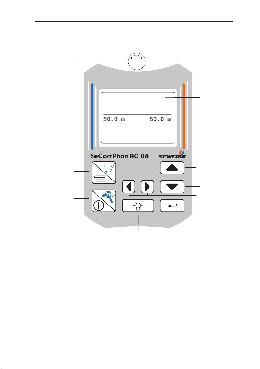
Illustration SeCorrPhon AC 06
Mikrophone
key/
Menu key
Magnifying-
glass key/
ON/OFF key
Light key
Central
screen
Arrow keys
Enter key
Rotary
regulator
pipe data
start
continue
Page 4
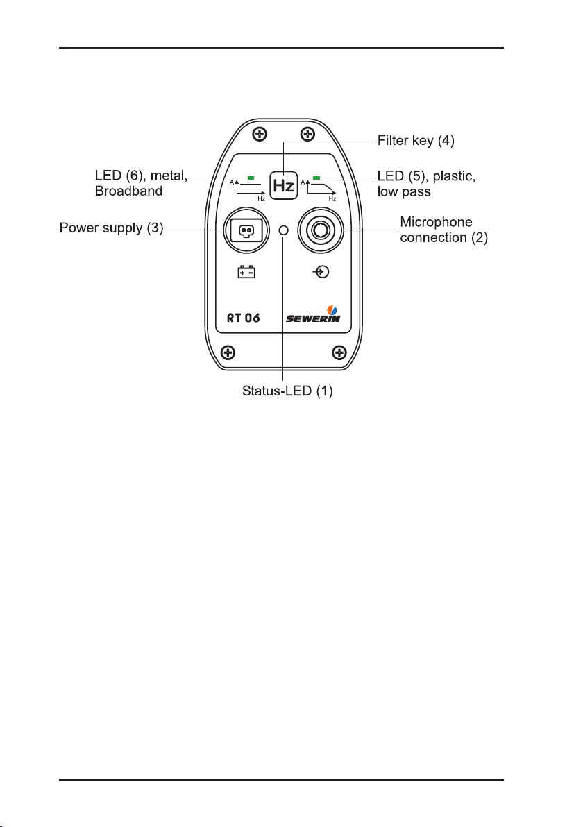
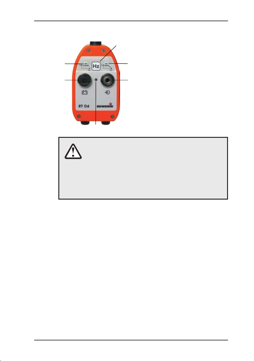
Illustration RT 06
Page 5

Operating Instructions
01.06.2007 – V 1.X – 105723 – en-us
SeCorrPhon AC 06
Page 6
Warranty & Used symbols
To ensure reliable operation and safety, it is required to pay attention to
the following notes.
Hermann Sewerin GmbH is not liable for damage caused by failure to
comply with these notes. The guarantee and liability conditions of the sales
and delivery conditions of Hermann Sewerin GmbH are not extended by
the following notes.
This product may only be taken into operation after reading thoroughly
the accompanying operating instructions.
This product may only be used for intended applications.
This product is destined for industrial and commercial applications.
Repairs may only be performed by the manufacturer or appropriately
trained staff.
The manufacturer is not liable for damage resulting from arbitrary modications of the product.
Only spare parts may be used which are approved by Hermann Sewerin
GmbH.
Only approved battery types may be used.
Technical changes within the scope of further development reserved.
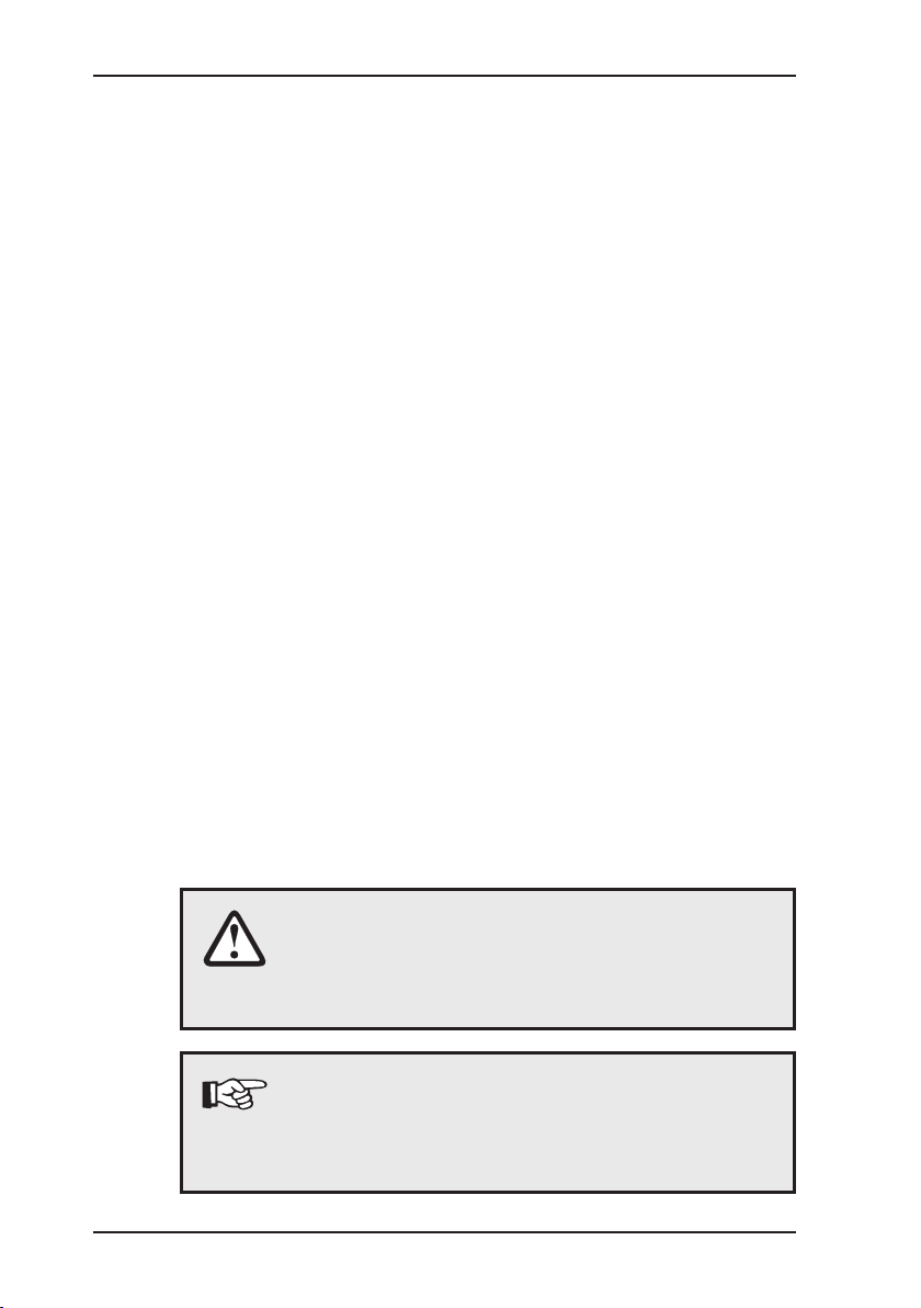
Used symbols:
CAUTION!
This symbol is used to indicate dangers which may
either result in hazards for the operators or in severe
damage – or even destruction – of the product.
Note:
This symbol is used to call attention to information
and tips which may be helpful and which are exceeding the basic operating procedures.
Page 7

I
Contents Page
1 Functional description ............................................................1
1.1 Use ............................................................................................1
1.2 How electroacoustic water leak detection works .......................1
1.3 How acoustic pipeline detection works .....................................1
1.4 How correlation works ...............................................................2
2 Starting up ............................................................................... 3
2.1 Starting up for the rst time .......................................................3
2.2 Switching on and off for electroacoustic water leak detection ........4
2.3 Switching on for correlation .......................................................5
2.3.1 Channel allocation ..................................................................6
2.3.2 Radio transmitter RT 06 .........................................................7
3 Controls ...................................................................................8
3.1 ON/OFF key/Magnifying-glass key ...........................................8
3.2 Rotary regulator ........................................................................9
3.3 Enter key .................................................................................10
3.4 Microphone key/Menu key ...................................................... 10
3.5 Left/right arrow keys ................................................................10
3.6 Up/down arrow keys ................................................................ 11
3.7 Light key ..................................................................................11
3.8 Adjusting the contrast ............................................................. 11
4 Electroacoustic water leak detection ..................................12
4.1 Display ....................................................................................12
4.1.1 Analog display ......................................................................12
4.1.2 Digital display .......................................................................12
4.1.3 Small digital display ..............................................................12
4.1.4 Loudspeaker symbol ............................................................12
4.2 Menu ....................................................................................... 13
4.2.1 Filter ..................................................................................... 13
4.2.2 Hearing protection ................................................................14
4.2.3 “MAX” mode ........................................................................15
4.2.4 Default values ......................................................................15
4.2.5 Measuring mode ..................................................................15
4.3 Probe overview .......................................................................16
4.3.1 Ground microphone BO-4 ....................................................16
4.3.2 Ground microphone 3P-4 .....................................................16
Page 8

II
Contents Page
4.3.3 Carrying rod H-4 ...................................................................16
4.3.4 Test rod T-4 ..........................................................................17
4.3.5 Piezo microphone EM 30 .....................................................17
4.4 Preliminary detection ...............................................................18
4.5 Locating leaks ......................................................................... 21
5 Performing a correlation measurement ..............................23
5.1 Entering pipe data ..................................................................23
5.2 Starting a measurement ..........................................................24
5.3 Analyzing results .....................................................................25
5.3.1 Filtering ................................................................................26
5.3.2 Cursor ..................................................................................26
5.3.3 Zoom ....................................................................................27
5.4 Continuing a measurement .....................................................28
6 Measuring the sound velocity .............................................29
6.1 General ...................................................................................29
6.2 Performing a measurement .....................................................29
7 Charging equipment ............................................................. 31
7.1 Battery condition .....................................................................32
7.2 Charging / battery maintenance ................................................33
8 Menu (in correlator mode) ....................................................34
8.1 Menu structure ........................................................................ 34
8.2 Listening ..................................................................................35
8.3 File ..........................................................................................35
8.3.1 Saving .................................................................................. 35
8.3.2 Opening ................................................................................36
8.3.3 Deleting ................................................................................37
8.4 Filtering ...................................................................................37
8.4.1 Automatic ltering .................................................................37
8.4.2 Manual ltering .....................................................................37
8.4.3 Setup ....................................................................................40
8.4.3.1 Frequency analysis ........................................................... 40
8.4.3.2 Filter limits .........................................................................40
8.4.3.3 Filter basis .........................................................................41
8.4.3.4 Filtering method ................................................................41
Page 9

III
Contents Page
8.5 Measuring method ..................................................................41
8.6 Measuring parameters ............................................................ 41
8.6.1 Noise suppression ................................................................41
8.6.2 Measuring time .....................................................................43
8.6.3 Summation / Averaging ..........................................................43
8.6.4 Mode of curve ......................................................................43
8.6.5 Type of correlation ................................................................ 44
8.6.6 Sampling frequency .............................................................44
8.6.7 Table ..................................................................................... 45
8.6.8 Default values ......................................................................46
8.7 Components ............................................................................46
8.8 Setup .......................................................................................47
8.8.1 Date, time .............................................................................47
8.8.2 Language ............................................................................. 47
8.8.3 Radio / cable .......................................................................... 48
8.8.4 System ................................................................................. 48
8.8.5 Name ....................................................................................48
8.8.6 Service ................................................................................. 48
9 Options for optimizing measurement results .....................49
9.1 Changing the number of averaging procedures ......................49
9.2 Using lters .............................................................................49
9.3 Automatic ltering ....................................................................50
9.4 Checking the microphone connection .....................................50
9.5 Using accessories ...................................................................50
9.6 Changing location ...................................................................50
9.7 Saving time .............................................................................50
10 Communication with the PC ................................................51
10.1 Requirements ..........................................................................51
10.2 Installing the software and establishing a connection .............51
11 Technical information ...........................................................53
12 Accessories ...........................................................................54
12.1 Accessories for electroacoustic water leak detection .............. 55
13 Error messages .....................................................................56
Page 10

IV
Contents Page
14 Hints on Disposal ..................................................................58
Appendix ..............................................................................................59
EC Declaration of Conformity ................................................................59
Index ......................................................................................................60
Page 11
1
1 Functional descriptionFunctional description
1 Functional description
1.1 Use
The SeCorrPhon AC 06 is used for electroacoustic water leak
detection and acoustic pipeline location. It can also detect leaks
in underground pressure line systems by correlation.
CAUTION!
To comply with FCC RF exposure compliance requirements, a separation distance of at least 20 cm
must be maintained between the antenna of the
transmitter RT 06 and all persons.
The antenna used for this transmitter must not be
co-located or operating in conjunction with any other
antenna or transmitter.
1.2 How electroacoustic water leak detection works
The SeCorrPhon AC 06 is used to detect water leaks by
electroacoustic means. The device is used in conjunction with
various microphones which are listed in section “Accessories”.
When pressure pipelines leak, water gushes out of the crack into
the ground.
The consequences:
The pipe material begins to vibrate at the leakage point. These
vibrations are transmitted by the pipe and can even be felt at
distant contact points, e.g. ttings. The SeCorrPhon AC 06 makes
this structure-borne sound audible.
The water jet and the pipe in the vicinity of the leak also cause
the ground to vibrate. These vibrations are transmitted through
the ground to the earth’s surface where they manifest themselves
as ground noise.
The human ear continues to play a crucial role in electroacoustic
leak detection. With the right training, it can compare the type and
sound of different noises and distinguish between the noise of a
leak and background noise.
Page 12

2
1 Functional descriptionFunctional description
1.3 How acoustic pipeline detection works
Plastic pipes cannot be located by conventional electromagnetic
means because they are not electroconductive.
The acoustic method of locating pipes applies a different principle:
Pipes transmit mechanical vibrations better than the surrounding
ground. When the pipe is caused to vibrate appropriately, these
vibrations are transmitted along the pipe and then through the
ground to the earth’s surface. Here they can be picked up using
a ground microphone and the corresponding receiver with
headphones according to the water leak detection principle.
Just like with water leak detection, the pipeline is usually wherever
the greatest intensity is detected. Fiber cement pipes and metal
pipes can also be located in this way.
If you want to locate pipes by acoustic means, follow the operating
instructions for the vibration detector (e.g. COMBIPHON). To
locate the pipe, proceed as you would when detecting a water
leak. The SeCorrPhon AC 06 offers an extra mode to help you
locate the pipeline (see section 3.4).
1.4 How correlation works
Sensitive microphones record the noise from leaks at accessible
ttings and transmit them by radio to the correlator.
The SeCorrPhon AC 06 then calculates the position of the
leak using Fast Fourier Transformation (FFT = mathematical
calculation rule).
Additional functions allow you to, for example, improve the leak display,
enter several sections of pipe or measure the sound velocity.
Radio transmitter RT 06 can automatically measure the input level
of the microphone and optimally adjust its amplier modulation
accordingly. Features such as the microphone used, the battery
condition and the amplier setting are transmitted to the correlator
by radio data where they are analyzed. This ensures optimal results
in all situations with maximum ease of use (switch on by plugging in
the microphone).
Note:
These operating instructions refer to the SeCorrPhon
AC 06. They explain the functions of software
version 1.X. The manufacturer reserves the right
to make technical changes..
Page 13
3
2 Starting upStarting up
2 Starting up
2.1 Starting up for the rst time
CAUTION!
The batteries of the AC 06 and RT 06 must be fully
charged once before starting up for the rst time.
If the batteries are only partially charged, their capacity and consequently their operating time may
be reduced.
CAUTION!
Safety measures
Do not use the headphones at a high volume.
Hearing specialists warn against using headphones at a high volume constantly or for a prolonged period.
Set the volume so that you only hear the sounds
at a moderate level.
Disable the headphones as soon as you realize
that interference noise may occur (footsteps,
vehicles etc.).
Disable the headphones when the microphone
is in motion.
Please note that it is more difcult to pick up
sounds in trafc.
Page 14
4
2 Starting upStarting up
2.2 Switching on and off for electroacoustic water leak detectionSwitching on and off for electroacoustic water leak detection
If you switch the device on as follows, you will be in what is known
as AQUAPHON mode. Certain functions are only possible in this
mode.
Place a probe in the appropriate input
The software version will appear in the display
The condition of the batteries
will appear in the display
Th e type of probe that is
plugged in is recognized automatically
Remove the probe to switch
off the systemstem
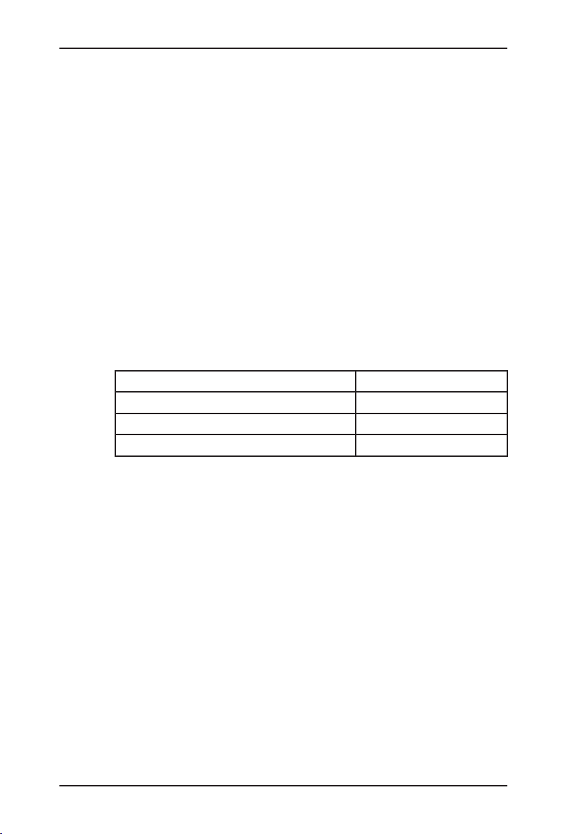
Type of microphone Display
Ground microphone BO-4 and 3P-4 BO-4 / 3P-4
Test rod T-4 T-4
Piezo microphone EM 30 M 01
Page 15

5
2 Starting upStarting up
2.3 Switching on for correlation
If you switch the device on as follows, you will be in what is known
as correlator mode. Certain functions are only possible in this
mode, others are not available.
Attach the two piezo microphones to accessible ttings.
When the round magnet is
screwed onto the piezo microphone, remove the very securely attached round magnet
protector if necessary.
Insert the two microphone connection cables into the sockets
of the RT 06 radio transmitters
(1). If you are only using one
RT 06, you must connect one
microphone directly to the
input (2) of the AC 06.
LED 1 on the RT 06 should
light up green.
Connect the headphones to
the input (3) of the AC 06.
Switch on the AC 06 by holding down the ON key.
The main screen displaying
the software version number
and the battery capacity will
briey appear.
Next the main screen (see
inside cover). From here you
can go to the menu (menu
key) or perform one of the
functions.
To switch the appliance off,
hold down the ON key until it
responds.
1
3
2
Page 16
6
2 Starting upStarting up
2.3.1 Channel allocation
Channel 1 Channel 2
Denotes „Battery
empty“ message
RT 06-1 RT 06-2
Display Left Right
Model with one
radio channel
Direct microphone
connection to the
AC 06
Orange radio
transmitter 22
Model with two radio channels
Blue radio
transmitter 1
Orange radio
transmitter 2
Only one radio
transmitter in use
(e.g. if faulty):
Version 1
(blue radio
transmitter in use)
Blue radio
transmitter 1
Direct microphone
connection to the
AC 06
Version 2
(orange radio
transmitter in use)
Direct microphone
connection to the
AC 06
Orange radio
transmitter 2
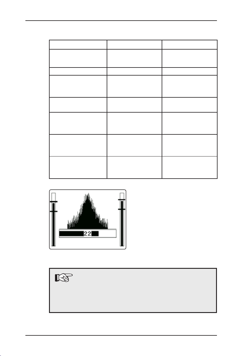
The noise intensity of the two
microphone channels is displayed to the left and right of
the correlation function during
the correlation measurement.
Note:
Note!
A microphone can also be connected directly to
an AC 06 model with two radio transmitters, e.g. if
one of the radio transmitters is faulty (see section
8.8.3).
started
Page 17
7
2 Starting upStarting up
2.3.2 Radio transmitter RT 06
Radio transmitter RT 06 can
be operated with various sen-
sors, EM30 microphones and
the HA hydrophone. It is recommended to use active lter
ZF01 if you want to lter out
interference noise or if you
only want to transmit a certain
acoustic frequency range to
correlator AC 06.
CAUTION!
Always connect the sensor to the measuring point
rst (connect microphone to slide gate, hydrants
etc.) before switching on the RT 06 by plugging the
sensor into the socket (2).
This ensures that the automatic amplication in the
RT 06 is set quickly and correctly.
The RT 06 is switched on by plugging the sensor into the socket
(2).
Always press the lter key (4) for plastic piping. The right LED
(5) lights up to indicate the switch. At this setting only the lower
frequencies (low pass) are transmitted to the correlator by radio.
This often increases the quality of the correlation measurement.
Every time the RT 06 is switched on all frequencies are transmitted and the left LED (6) lights up.
The carrying knob attached to the top of the aerial is ideal for
transportation.
The LED (1) indicates the status of the RT 06:
Operation: green
Undervoltage: ashing red
Charging: 1 x ashing green
Buffering: 2 x ashing green
Not charging: red (because temperature below 0 °C)
1
2
3
6
5
4
Page 18
8
3 Controls
3 Controls
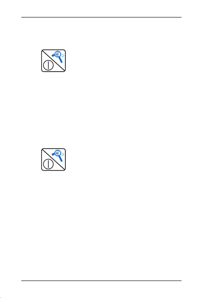
3.1 ON / OFF key / Magnifying-glass key
In correlator mode this key is
the ON/OFF key.
To switch on and off, hold
the key down until the AC 06
responds.
Pressing the key briey stops
the current function (e.g. ongoing correlation). If you are in
the menu, you can move up
a level by briey pressing the
ON key.
If you stop a correlation, you
can enlarge the image (correlation function). Press any key
to return to the normal view.
In AQUAPHON mode this key is
the magnifying-glass key.
The magnifying-glass key
sets the basic amplication.
10 = high noise amplication
100 = average noise ampli-
cation
1000 = low noise amplication
Basic amplication is useful for
adapting to extreme situations.
The higher the basic amplication, the louder the noise in the
headphones.
Page 19

9
3 Controls
The scale for the analog display
is also set. Change the basic
amplication when the analog
display is constantly in the bottom/top range.
If the basic amplication is too
high, the analog display scale
will ash.
3.2 Rotary regulator
The rotary regulator serves the
following functions in correlator
mode:
Turning the regulator moves
the selection or the cursor to
the left/right or up/down.
In input fields with numeric
values (e.g. for entering the
pipe length), you can change
the value directly by turning
the knob.
Pressing the rotary regulator switches the direction of
movement between up/down
and left/right. Pressing the
rotary regulator has the same
effect as the Enter key.
In AQUAPHON mode the enter
key is only used to set the volume
and for activation/deactivation.
Page 20
10
3 Controls
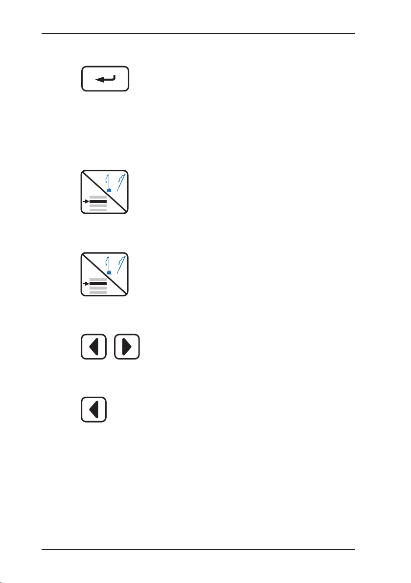
3.3 Enter key
Pressing the Enter key performs the function that is currently selected. Selecting the
“cancel” function in the menu
takes you back to the main
screen.
3.4 Microphone key / Menu key
In correlator mode this key is
the menu key.
Pressing the menu key brings
up the menu.
In AQUAPHON mode this key
is the microphone key.
Pressing the microphone key
activates the AC 06. Pressing it again deactivates the
AC 06.
3.5 Left / right arrow keys
Pressing the ar row keys
takes you through the functions to the left and right. You
can also make a selection in
some menus.
When you are in a menu, you
can move up a level with the
“left” arrow key, albeit only
when no left or right cursor
movement is possible at the
respective position.
Page 21
11
3 Controls
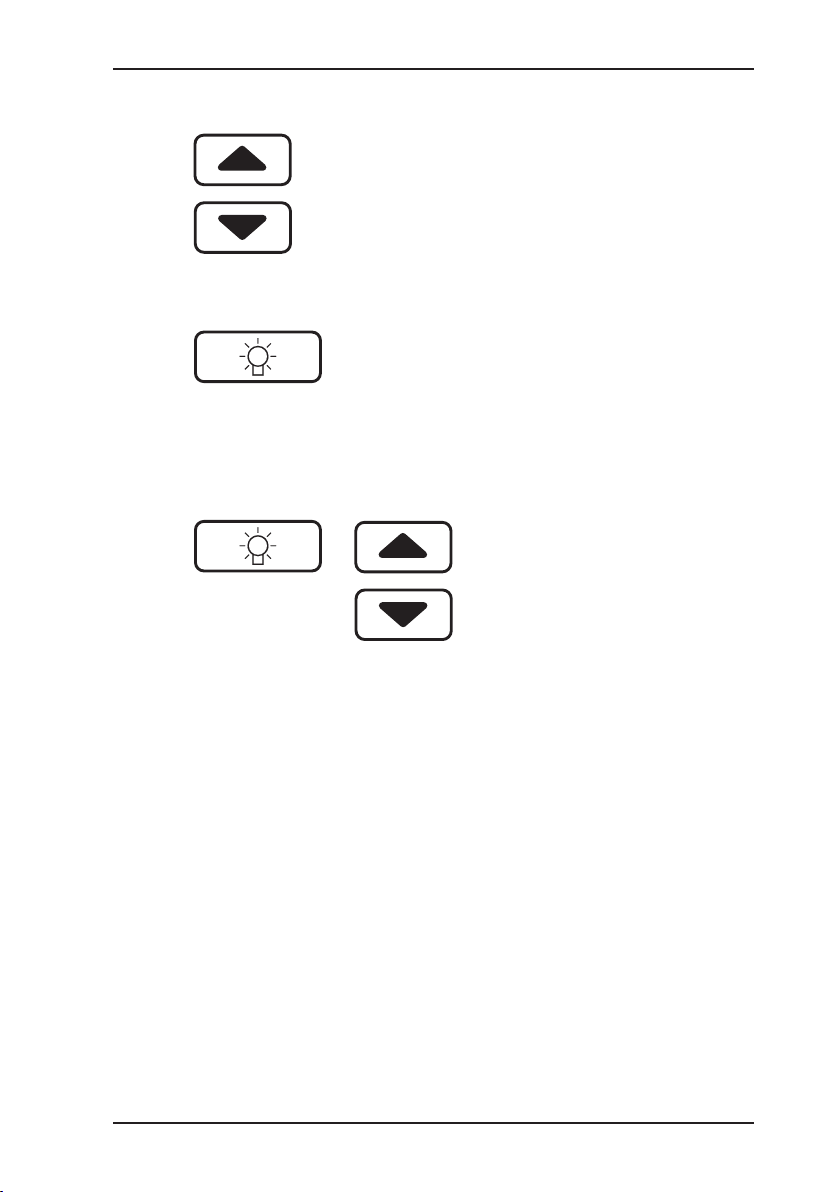
3.6 Up / down arrow keys
Pressing the ar row keys
takes you up and down within
the menus. You can also make
a selection in some menus.
3.7 Light key
Pressing the light key illumi-
nates the display. The light
remains on for a short time
before going off automatically.
(see section 8.8.4).
3.8 Adjusting the contrast
The display contrast is automatically controlled according
to the temperature.
You can adjust the contrast
manually by holding down the
light key and then pressing
the arrow key up or down.
Page 22
12
4 Electroacoustic water leak detectionElectroacoustic water leak detection
4 Electroacoustic water leak detection
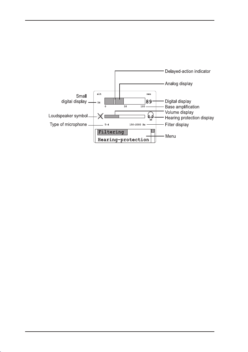
4.1 Display
The display contains the following display elements:
4.1.1 Analog display
The analog display shows the current measurement value.
(See also section 3.1).
4.1.2 Digital display
The digital display (new) - depending on the rmware language -
displays the smallest measured value during a single measurement.
In “MAX“ mode, the digital display always shows the highest
measured value.
4.1.3 Small digital display
The small digital display (old) always shows the previously measured value for comparison purposes.
4.1.4 Loudspeaker symbol
The loudspeaker symbol shows that the headphones of the AC 06
are activated.
Page 23

13
4 Electroacoustic water leak detectionElectroacoustic water leak detection
4.2 Menu
4.2.1 Filter
The frequency lter setting can be changed in the lter menu.
The band pass of the lter can be adjusted from 1 Hz to 9950
Hz; it is at least 300 Hz wide.
Leak noises have different ranges in which they can be heard
particularly well. Even the same sound is perceived differently by
different people. A band pass can be set to optimize the acoustic
perception. This means that only one particular frequency range
will be relayed to the headphones. You can either nd the best
setting yourself by trial and error or the AC 06 can search for it
automatically.
Automatic search for the best frequency range
With the lter optimization function the AC 06 can automatically
search for the best frequency range provided this is done when
there is little background noise interference. Furthermore, the
noise from the leak, in particular the ground noise, should already
be discernible.
Automatic
The AC 06 records and analyzes a “noise sample”.
The display will show various frequency ranges during the
analysis process. You will also hear on the headphones the
noise produced from the displayed lter values.
The AC 06 sets the frequency range which distinguishes the
leak particularly vividly.
Default
Here you can reset the default band pass setting (factory set-
ting) for the probe that is currently plugged in. The band pass
setting for other probes will not be reset.
Page 24

14
4 Electroacoustic water leak detectionElectroacoustic water leak detection
4.2.2 Hearing protection
The AC 06 features a hearing protection function which reduces
the volume of the headphones in case of sudden, loud noises. If
the noise gets even louder, the headphones will be switched off.
Once the source of the noise goes quiet, the AC 06 recommences
its work. The hearing protection function prevents the ears from
being exposed to excessive acoustic pressure.
This headphones symbol appears when the hearing protection function is activated.
Sensitive
The hearing protection function activates at a low (quiet) threshold.
Average
The hearing protection function activates at a moderate threshold
(default setting).
Insensitive
The hearing protection function activates at a high (loud) threshold.
CAUTION!
Only use SEWERIN headphones, as these are
specially designed for the AC 06.
Note:
The hearing protection function should only be set
to “sensitive” for quiet ambient sounds so that it
activates with moderate noise. In situations where
loud ambient noise is common, the threshold should
be set to “average”. In exceptional circumstances
the threshold can be set to “insensitive”. The hear-
ing protection function is only activated at very loud
noise values. To prevent the hearing protection
function from activating very frequently and thus
making leak detection more difcult, the headphone
volume and the basic amplication should not be
set too high!
Page 25

15
4 Electroacoustic water leak detectionElectroacoustic water leak detection
4.2.3 “MAX” mode
This mode helps detect pipelines by acoustic means. Instead
of showing the minimum values, this mode always shows the
maximum values.
“MAX” appears in the display when this mode is activated. The
mode is not saved.
4.2.4 Default values
This function restores (resets) all the default settings (factory settings) of AQUAPHON mode.
4.2.5 Measuring mode
This setting determines how the rotary regulator activates/deactivates a measurement or the headphones.
1 x press
The measurement is activated by briey pressing the rotary regulator and will remain active for as long as the rotary regulator is
pressed down. The measurement is deactivated when the rotary
regulator is released. This key principle is the default setting.
2 x press
The measurement is activated by briey pressing the rotary regulator. The measurement is only deactivated when you press the
rotary regulator again (switch principle).
Page 26

16
4 Electroacoustic water leak detectionElectroacoustic water leak detection
4.3 Probe overview
4.3.1 Ground microphone BO-4
Ground microphone BO-4 is
used to locate leaks under xed
surfaces.
4.3.2 Ground microphone 3P-4
Ground microphone 3P-4 is used
to locate leaks under non-xed
earth surfaces. A spike can be
screwed on for soft ground. The
three feet provide stable contact
at all times.
4.3.3 Carrying rod H-4
The carrying rod can be used
with both ground microphones.
Microphone BO-4 or 3P-4 is
screwed onto the bottom end of
the carrying rod.
Page 27

17
4 Electroacoustic water leak detectionElectroacoustic water leak detection
4.3.4 Test rod T-4
The test rod is used in the preliminary detection of leaks. The
test rod is attached to ttings on
the pipe that is under examination.
4.3.5 Piezo microphone EM 30
The piezo microphone is used
for preliminary detection and for
detection mainly in buildings.
Thanks to the screw-on M 10 tripod, it can be used for oors and
for ttings and sections of piping
with the straight probe.
Page 28

18
4 Electroacoustic water leak detectionElectroacoustic water leak detection
4.4 Preliminary detection
Metal pipe materials transmit
structure-borne sound over a
particularly wide area. The test
rod can therefore be used very
effectively for pre-detection.
Connect the headphones to
the AC 06.
Connect the test rod to the
AC 06.
Place the test rod at the rst
measurement location.
Activate the AC 06 with the
rotary regulator or the micro-
phone key.
During the measurement the
loudspeaker symbol is not
crossed out in the display.
The analog display shows
the current volume measurement.
The n oise can be hea r d
through the headphones.
During this measurement, the
large digital display shows the
smallest value measured.
During this measurement, the
small digital display shows
the smallest value measured
during the last measurement.
(This value is 0 during the rst
measurement.)
During this meas ure men t
th e an alog disp lay shows
the smallest measured value
inverted.
Page 29

19
4 Electroacoustic water leak detectionElectroacoustic water leak detection
To deactivate the AC 06 re-
lease the rotary regulator or
press the microphone key
again.
If the AC 06 does not go off
when you release the rotary
regulator, the function of the
ro tary regulato r h as been
changed. In this case press
the rotary regulator again.
Place the test rod at the next
measurement location and
proceed as above.
The pre vio usly measu red
value will now appear in the
small digital display for comparison purposes.
Page 30

20
4 Electroacoustic water leak detectionElectroacoustic water leak detection
The illustration above is an example of what might be displayed
in the course of detecting a water leak.
The sound is loudest close to the leak, the further away you get,
the quieter it is.
Left: The analog display shows approx. 30% scale division, this
is the current noise value.
The analog display, however, often uctuates heavily due to the
changing ambient noise. It is even hard to discern a trend. For
this reason the large digital display (number 16) shows the smallest noise value measured at this measurement location over the
measuring time (current slider value). Even if the noise gets
louder (ambient), the display will freeze, if the noise gets quieter,
the display will continue to fall.
In the analog display the numeric value 16 will also be displayed
as an inverse segment.
The small digital display shows “0”: there is no value in the
memory yet.
Centre: The analog display shows approx. 60% scale division.
The large digital display (number 38) shows a greater value than
at the measurement location on the left. This indicates that the
location of the leak is closer.
The small digital display now shows “16”: it is a reminder of the
result from the last measurement location (last slider value).
This helps you determine whether or not you have reached the
leak, or if you have already gone past it.
Right: The current slider value has dropped because the leak is further away. The last slider value shows “38” again for comparison.
Page 31

21
4 Electroacoustic water leak detectionElectroacoustic water leak detection
4.5 Locating leaks
Non-metallic pipe materials transmit the structure-borne sound
less effectively. It is therefore not enough to examine the ttings.
A ground microphone is used to perform an additional check on
the length of piping between the ttings.
Using the ground microphone at regular intervals enables the leak
to be located without excavation. Once again, the AC 06 shows
an accurate optical comparison of the noise intensities.
The illustration above is an example of how the display changes
when a leak occurs.
Connect the ground microphone to the AC 06.
Place the ground microphone
on the ground.
Activate the AC 06 with the
rotary regulator or the micro-
phone key.
A loudspeaker symbol appears in the display during the
measurement.
The analog display shows
the current volume measurement.
Page 32

22
4 Electroacoustic water leak detectionElectroacoustic water leak detection
Th e c urrent n oise can be
heard on the headphones.
The digital display shows the
smallest value measured.
The small digital display shows
the value measured previous-
ly. This value is 0 for the rst
measurement.
The smallest value measured
is shown inverted in the analog
display.
To deactivate the AC 06 re-
lease the rotary regulator or
press the microphone key
again.
If the AC 06 does not go off
when you release the rotary
regulator, the function of the
ro tary regulato r h as been
changed. In this case press
the rotary regulator again.
Place the ground microphone
at the next measurement location and proceed as above.
The pre vio usly measu red
value will now appear in the
small digital display for comparison purposes.
Using the ground microphone,
listen to the section of pipe
where you suspect the leak is
situated.
The illustration on the previous
page is an example of what
the display shows when you
cross a leak.
Page 33

23
5 Performing a correlation measurementPerforming a correlation measurement
5 Performing a correlation measurement
5.1 Entering pipe data
The pipe data must be entered in preparation for each measurement.
Using the arrow keys select
“Pipe data” from the menu
and conrm by pressing the
Enter key. You will be asked
how many pipe sections there
are.
Select “one”, “two”, or “three”
pipe sections accordingly with
the arrow keys and then press
Enter.
Next you will be asked to enter
the pipe length. The left/right
arrow keys allow you to move
between the digits.
The up/down arrow keys
increases or reduces the respective digit by one.
Conrm the length by pressing
Enter.
Select the material of the pipe
section from the list using the
arrow keys or select “manual“
to enter the sound velocity
directly.
Please note: the values in
the list are approximate and
can cause inaccuracies (see
section 6).
Select the pipe diameter from
the list using the arrow keys.
Repeat these entries for the
second and third sections of
pipe as necessary.
Page 34

24
5 Performing a correlation measurementPerforming a correlation measurement
Note:
As well as the standard “cross correlation”, the
AC 06 can also perform “auto correlation”, see section 8.6.5.
5.2 Starting a measurement
This function must be selected to measure a section for the rst
time, or after the rst measurement if errors have occurred (trans-
mitter not switched on, badly connected microphone etc.).
Using the arrow keys select
“Start” and conrm by pressing the Enter key. Use the
headphones to check the progression of the measurement
acoustically (safety measures:
see section 2.1).
pipe data
start
continue
Start
cancel
100.0 m
steel
125 mm
1280 m/s
A summary of the pipe data
entered will be shown.
Mark “start” using the arrow
keys. Press the Enter key.
The correlation measurement
will begin.
Page 35

25
5 Performing a correlation measurementPerforming a correlation measurement
De pending on the setting
(see section 8.6.2) 16, 32, 64
or 128 averaging procedures
(measuring processes) will be
performed.
The display will show which
averaging procedure is currently being performed.
The correlation function is
updated continually during the
measurement.
You can pause the correlation
measurement at any time by
briey pressing the ON key.
You can continue the paused
measurement at any time.
The result will be shown after
the measurement. The illustra-
tion on the left is an example
of the progression of the correlation function. The mode of
curve depends on the setting
in the Filters/Setup menu.
5.3 Analyzing results
The correlation function indicates in the form of peaks
where a leak may be located.
The “x-axis” shows the time
difference in ms (milliseconds).
The marking is automatically
set at the highest peak.
pipe data
start
continue
pipe data
start
continue
Page 36

26
5 Performing a correlation measurementPerforming a correlation measurement
CAUTION!
If you see a peak right in the middle of the screen,
this may indicate that radio transmitter RT 06 is too
close to the AC 06 (receiver). Increase the distance
between the two appliances to several (5 – 10)
meters.
5.3.1 Filtering
Please read section 8.4 on the basic principles of ltering.
The ltering option here from the function in the main screen offers
faster access to manual functioning than via Menu / Filter / Manual.
The range of functions here is, however, limited.
Select “Filter“ in the main screen.
The left lter limit ashes and can be set.
Enter key: calculates the result function; the other lter limit can
be set (can be repeated as often as you wish).
ON key: returns to the main screen, the result is displayed.
5.3.2 Cursor
If you select the “cursor” function with the arrow keys, you
can place the cursor in any
position you desire with the
arro w keys or the rotary
regulator.
The measurement will be recalculated immediately in accordance with the marked position.
The time indicated beside the
cursor indicates the time difference setting.
The distances stated under the
correlation function indicate the
distance of the cursor position
from the two microphones.
Page 37

27
5 Performing a correlation measurementPerforming a correlation measurement
5.3.3 Zoom
The “zoom” function allows you
to enlarge areas of the correlation function.
Select “zoom” with the arrow
keys.
The “right” arrow key en-
larges the mode of curve.
Position bar 1 below the correlation function shows which
part of the entire pipe length is
displayed.
The “left” arrow key displays
the entire correlation function
again.
Note:
Subjective evaluation of the form of the cross correlation function (CCF) is particularly important when
applying the correlation procedure. The knowledge
required for this cannot be taught as a theory; practical experience is essential.
The measurement is based on the value marked in
the CCF and on the pipe data you have entered. The
CCF represents, in simple terms, the time relationship in terms of quality of the two sounds recorded
by the two microphones to each other.
It is impossible to distinguish between the (sought)
leak sounds and the background noise. The measurement may not always, therefore, indicate a
leak; sources of background noise can also be
detected!
If there is “no“ noise present, a random measurement will be calculated. In such cases you should
look for other connection points for the microphones
where the leak noise can be picked up much more
clearly.
Page 38

28
5 Performing a correlation measurementPerforming a correlation measurement
5.4 Continuing a measurement
This function starts the correlation measurement with the old
pipe data. All the previous results from any prior correlation will
be retained.
Any pipe data which has changed since the last correlation will
not be taken into account.
You should continue the measurement if the result of the rst
correlation measurement (number of averaging procedures e.g.
32) is not yet reliable enough.
Using the arrow keys select
“conti nue” and confirm b y
pressing the Enter key.
The measuring procedure is
the same as if you were starting a new measurement.
pipe data
start
continue
Page 39

29
6 Measuring the sound velocity
6 Measuring the sound velocity
6.1 General
Sound velocity measurements are necessary because it is important to enter the correct sound velocity for an exact measurement.
The sound velocity values are contained in an internal table (see
section 8.6.7). The sound velocity data in “pipe data” is, however,
approximate. Furthermore, you may not know the pipe dimension
or the material.
This function requires a source of noise,
for example, an open hydrant,
which produces a clear symbol in the CCF, in other words is
“correlatable”,
which must have a known position,
which must not be positioned in the “middle area” of the measuring section in order to increase accuracy.
If the measuring section is comprised of several pipe sections
(material or dimension intersections), the sound velocity measurement will produce erroneous results.
6.2 Performing a measurement
The measuring procedure is very similar to a correlation measurement.
First connect the microphones and radio transmitter as de-
scribed (see sections 2.3).
Activate “Measuring method” “Sound velocity” in the menu
(see section 8.5).
Select “Pipe data” from the menu and enter the data accord-
ingly.
When asked about a “man-made leak” you must enter the distance of the man-made leak from microphone 1:
If it is outside of the measuring section and beyond
microphone 1, enter 0 m for the distance.
microphone 2, enter the total length of the measuring section
for the distance, i.e. the „pipe length“.
–
–
Page 40

30
6 Measuring the sound velocityMeasuring the sound velocity
To create a source of noise, either generate a man-made leak
(e.g. open hydrant) or bang on the tting in quick succession
using a hammer.
Select „start“ using the arrow keys.
The measuring procedure will begin.
After the measurement, the correlation function will appear in
the display.
The cursor will automatically be placed at the position with the
greatest value. Check whether this position is your man-made
leak. If necessary, move the cursor to the man-made leak using the arrow keys or the rotary regulator.
If you select “accept“ in the menu:
The calculated sound velocity will be applied in the internal
memory.
You will exit the “measure sound velocity” measuring method
(and return to the “standard” measuring method).
Return to the main screen.
You can now perform a correlation measurement to detect the
real leak. When entering any modications to the pipe data,
also enter the calculated sound velocity by selecting “manual”
under pipe material.
If you select “cancel“ in the menu:
the calculated sound velocity will not be applied.
you will exit the “measure sound velocity” measuring method
(and return to the “standard” measuring method).
Return to the main screen.
–
–
–
–
–
–
Page 41

31
7 Charging equipmentCharging equipment
7 Charging equipment
Power is supplied to the AC 06
and the RT 06 by the integrated
NiMH batteries.
The AC 06 can be operated for
approx. 10 hours. The operating
time may be reduced considerably when using the display light
or in low outside temperatures
(display heating).
The RT 06 radio transmitter
can be operated for at least 8
hours.
Alternatively, (if the battery is
empty) the AC 06 and the RT
06 transmitter can be operated
using an external 12 V = power
source (e.g. vehicle cable).
Docking station HS 1.2 A and
the AC/DC adapter or the vehicle
cable are required for charging
or for external operation. The
AC 06 charges in 4 hours maximum, radio transmitter RT 06 in
5 hours maximum.
The vehic le cab le mus t be
plugged into socket 1 of the
docking station or socket 3 of the
RT 06 transmitter.
1
3
Page 42

32
7 Charging equipmentCharging equipment
The AC 06 and RT 06 transmit-
ters can also be charged directly
in the case.
To do this, connect vehicle cable
L or AC/DC adapter L to socket
1 in the case.
Cables 2 and 4 must be connected to each of the RT 06
transmitters and cable 3 must
be connected to docking station
HS 1.2 A.
7.1 Battery condition
The battery condition is shown in the AC 06 display in the form
of a battery symbol with the text
RT 06-1 or RT 06-1 or AC 06
if the respective component has less than approx. 15 minutes
operating time remaining.
The status LEDs provide further information on the RT 06 (see
section 2.3.2).
1
32 4
Page 43

33
7 Charging equipmentCharging equipment
7.2 Charging / battery maintenance
While charging, the AC 06 displays the remaining charging time
in hours. When in this mode the “battery maintenance” function
can be selected using the menu key. This discharges the battery
and recharges it again, thereby eliminating chemical deposits in
the battery and improving its storage capacity. The process takes
approx. 10 hours and should be carried out approx. every 60 days,
especially with appliances which are not used often.
Symbols and what they mean during the charging process:
“Battery maintenance” is acti-
vated
The temperature is below 0 °C,
the battery cannot be charged.
The temperature is above 45 °C,
the battery cannot be charged.
Page 44

34
8 Menu
8 Menu (in correlator mode)
8.1 Menu structure
(*) Settings which remain in effect even
after the device has been switched
off. All others are reset to the default
values. (See section 8.6.8)
Listen
Channel 1
Channel 2
Channel 1 and 2
File
Open
Low resolution
High resolution
Noise
Store
... see „Open“
Delete / All
... see „Open“
Filtering
Automatic
Manuel
Setup (*)
Subs. treatment
Automatic
Manuel
Off / On
Filter limit
Filter basis
Coherence
Cross spectrum
Spectrum KA 1
Spectrum KA 2
Filtering method
Rectangle
Hanning
Measuring method
Standard
Sound velocity
Parameter
Noise suppression
Automatic
Manuel
Off
Measuring time
Standard =32
Summation / Average
Summation
Averaging
Mode of curve (*)
CCF positive
CCF pos. + neg.
TOP pos. + neg.
Type of correlation
Cross correlation
Auto Corr. CH 1
Auto Corr. CH 2
Sampling frequency
Automatic
Manuel
Table (*)
Standard values
Components
Setup (*)
Date, Time
Language
Radio / Cable
System
Name
Service
Page 45

35
8 Menu
8.2 Listening
The “listen” function allows you to adjust the volume of the two
channels.
Using the arrow keys select the channel to be adjusted.
You can adjust the volume of the selected channel using the
arrow keys or the rotary regulator.
If “channel 1” is selected, you will hear channel 1 through both
ears (mono mode). The same applies for “channel 2”. If “channel 1 and 2” is set, you will hear both channels at the same
time (stereo mode).
8.3 File
In this menu you can open, save and delete individual measurements and noises. The data is led in the internal memory of the
AC 06 and can be accessed even after the appliance has been
switched off.
8.3.1 Saving
The following number of memory slots are available:
a) 50 memory slots (low resolution)
b) 25 (1 – 25) memory slots (high resolution)
c) 5 (1 – 5) memory slots (noises)
Note:
b) and c) share one memory area
Measurements saved at a low resolution cannot be processed
later, e.g. ltered.
Only the main screen can be viewed.
Functions: view main screen,
move cursor,
start, continue.
There are 50 memory slots of low resolution available.
Measurements saved at a high resolution can be processed later.
In other words, all functions that are possible after the end of a
Page 46

36
8 Menu
measurement (after a measurement has been stopped), are also
possible here.
Exception: it is not possible to “continue” the measurement.
There are up to 25 memory slots available, they are used together
with the memory slots for “noises”.
If you select “noises” approx. 7 seconds of the current noise is
saved.
Please note that the saving process takes approx. 35 seconds due
to the high storage volume. The process cannot be cancelled.
Use the arrow keys to select what you want to save: low reso-
lution, high resolution or noises.
Once you press the Enter key, the measurement or the noise
will be saved.
8.3.2 Opening
The “open” function allows you to reload measurements/noises.
Use the arrow keys to select what you want to open: low
resolution, high resolution or noises. Please note that it takes
approx. 25 seconds to load a noise. Conrm your selection by
pressing the Enter key.
A list containing the les stored in the AC 06 memory will ap-
pear.
Using the arrow keys select a le and then conrm by pressing the Enter key.
This le will appear when you open a measurement.
If you open a noise, the 7 second noise clip will be played on
repeat. You can cancel the playback by briey pressing the
ON key.
Page 47

37
8 Menu
8.3.3 Deleting
Using the arrow keys select what you want to delete: “low
resolution”, “high resolution” or “noises”. Conrm your selection
by pressing the Enter key. A list containing the les stored in
the AC 06 memory will appear.
Using the arrow keys select the le you want to delete and
then conrm by pressing the Enter key.
The le will be deleted.
8.4 Filtering
The lter function allows you to hide certain frequencies from the
correlation function to improve the result.
You can choose between manual and automatic ltering.
8.4.1 Automatic ltering
The AC 06 performs automatic ltering (processing control) after
a measurement. The lters are automatically optimized.
8.4.2 Manual ltering
An image will appear which will display a frequency response below (lter basis, see section 8.4.3.3) and the result above (mode
of curve, see section 8.6.4) from the set lters.
Page 48

38
8 Menu
Pressing the Enter key takes
you into processing mode.
Using the arrow keys select
which lter limit is to be adjusted:
- Filter left
- Filter right
- Hide left
- Hide right
Use the arrow keys to move
the relevant limit.
The corresponding frequency
will be shown in the display.
Light grey frequency ranges
will be hidden.
Black areas will be included in
the correlation.
If you want to enlarge the
frequency range, you must
rst change the lter limit settings in the Setup (see section
8.4.3.2).
Page 49

39
8 Menu
Using the arrow keys select
“OK”.
The set lters will be applied
and the frequency response
with the result w il l be updated.
Pressing the Enter key takes
you back to the “manual lter-
ing” mode of curve where you
can change the filter limits
again if necessary.
Selecting “back” takes you
back to the main screen, the
lter settings will remain effective.
left
ltering limit
right
cut off limit
left
cut off limit
right
ltering limit
zoom
filter right
cut off left
filter left
Page 50

40
8 Menu
8.4.3 Setup
Settings are saved in the setup so that you do not have to call up
the required individual functions again and again. Place the cursor
on the desired option and then press the Enter key.
8.4.3.1 Frequency analysis
The frequency analysis optimizes the coherence function lters
using statistical methods to achieve an optimal correlation result.
An automatic frequency analysis can be performed on ongoing
measurements and saved measurements.
Automatic
After each correlation procedure, automatic ltering is performed (see section 8.4.1).
Manual
After each correlation procedure the manual ltering menu will
appear (see section 8.4.2). The lter settings under “lter limits”
in the menu (see section 8.4.3.2) are used as the default.
Off
This switches off both of the processing options above.
8.4.3.2 Filter limits
Setting option for the lter settings to be used for manual ltering
(see section 8.4.3.1).
Factory setting: if you enter a sound velocity above or below
700 m/s for a measurement, the correlator will adjust itself to:
lower limit / Hz upper limit / Hz
< 700 m/s 5 500 Plastic
> 700 m/s 0 3000 Metal
It does not matter whether the sound velocity is entered by manually selecting the numeric value or by selecting the corresponding
pipe parameters.
Page 51

41
8 Menu
8.4.3.3 Filter basis
Here you can change the mode of curve of the frequency curve
for the lter settings.
Coherence
The similarity of the frequencies is displayed.
Cross spectrum
The cross spectrum from the two channels is displayed.
Spectrum, Ka 1
The frequency spectrum of channel 1 is displayed.
Spectrum, Ka 2
The frequency spectrum of channel 2 is displayed.
8.4.3.4 Filtering method
Under “square” the signal is ltered exactly at the marked position.
Under “Hanning” a “soft transition” is created around the marked
position.
8.5 Measuring method
The “measuring method” function allows you to switch between
the standard measurement (= correlation measurement) and the
sound velocity measurement (see section 6).
8.6 Measuring parameters
The “measuring parameters” submenus allow you to set various
parameters which affect the measurement.
8.6.1 Noise suppression
“Noise suppression” is a function to reduce the negative impact
of temporary interference noise (vehicles, pedestrians).
With “noise suppression” it is assumed that optimal results can
be achieved at moments when the noise (signal) measured is
relatively small. This is when the permanent leak noise is by and
large free from interference.
Page 52

42
8 Menu
When the signal is relatively high, the additional noises must stem
from a source of interference which has a negative effect on the
measuring result.
Noise suppression ensures that correlation (averaging) only takes
place when the signals are in a certain level range (volume). If
the signals are outside of the level range, the measurement will
be discontinued.
The level range is limited by the lower threshold and the upper
threshold. These thresholds are shown for signals 1 and 2 as
horizontal lines on the far left / far right of the display when the
measurement is taking place. The level range is always reset
when starting the measurement. The correlator uses the level
values measured at the start as a point of reference.
a) automatic
This setting is suitable for achieving good results in all standard
cases.
After a certain time, the level range is automatically raised slowly
if the current level values are permanently over the level range.
In the same way, the level range is lowered if the current level
values are permanently below the level range.
b) manual (default setting)
This setting is recommended if you want to work with maximum
noise suppression and have maximum individual inuence on
the measurement.
If the measurement is interrupted for too long because the noise
is too loud, the level range can be manually raised by pressing
“continue” and thus made less sensitive. The measurement will
continue as the user ignores a certain amount of interference
noise.
Once the current level values fall below the level range an automatic adjustment takes place and the correlator becomes more
sensitive to interference noise.
c) off
This setting should only be selected if the constantly heavily uctuating signals mean that the measurement is often interrupted
and correlation would not be possible otherwise.
Noise suppression is disabled. It is accepted that interference
noise occasionally masks the leak noise.
Page 53

43
8 Menu
8.6.2 Measuring time
The “measuring time” function allows you to specify how many
single measurements are to be performed before measurement
stops.
8.6.3 Summation / Averaging
The “summation” function uses all the individual results for the
mode of curve of the CCF and analyzes them equally.
The “averaging” function evaluates the individual results differently: the most recently performed measurement has the greatest
inuence on the CCF; the previous ones much less etc.
The “averaging” setting of the CCF thus tends to reect the cur-
rent noise.
8.6.4 Mode of curve
You can change the mode of curve of the correlation function:
CCF positive
The CCF only has positive values.
CCF pos. + neg.
The CCF contains positive and negative values.
TOP positive
The mode of curve is like the “CCF positive” one, but the top
values are usually more prominent.
TOP pos. + neg.
The mode of curve is like the “CCF pos. + neg.” one, but the
top values are usually more prominent.
Page 54

44
8 Menu
8.6.5 Type of correlation
The cross correlation uses channel 1 and channel 2 to measure;
the source of noise to be located must be within the measuring
section.
Auto correlation uses either channel 1 or channel 2. The sec-
ond signal required for correlation is produced by reecting the
noise to be located at a reection point. It must be received by
the channel in use.
As the energy from the reected noise is usually very low, this
procedure is rarely feasible. The chances are usually better if
there are gaseous media in the pipe.
The position of the reection point must be known for auto correlation.
The auto correlation function (ACF) always has a symmetrical
progression. Only the negative area of the ACF (delta t <0) is of
interest.
8.6.6 Sampling frequency
The continuous time signal of the channels used is scanned and
digitized at a certain frequency, the sampling frequency.
The lower the sampling frequency, the less calculating time is
required for averaging. However, the sampling theorem requires
a sampling frequency which is at least twice as high as the highest frequency contained in the signal! If the sampling frequency
setting is too low, measuring errors may occur. For this reason,
the sampling frequency should only be reduced in exceptional
circumstances, for noises of very low frequency.
The sampling frequency is at the maximum with “automatic”.
Select “manual” for a manual setting. You can change the sam-
pling frequency using the arrow keys.
All subsequent measurements will be performed at this sampling
frequency.
Page 55

45
8 Menu
8.6.7 Table
This menu offers a choice of 3 tables for the sound velocity measurement. You can choose between two set and one individually
editable table.
Table 1: Particularly good experience in France
Table 2: Internationally applicable
Table 3: Individually editable
Selecting a table
Select the respective row and press the Enter key. If you choose
individual table 3, another window will open which you should
conrm accordingly.
Creating and editing the table
When creating a table for the rst time, think about the basis (table
1 or 2) on which your table should be created. The values present
in the preset table are (in the background) copied into individual
table 3 (still blank) where they can be changed. Tables 1 and 2
will remain unchanged.
Select the desired table (table 1 or 2).
In the menu select Table – Individual – Edit.
You can now edit table 3.
Select the material from the list followed by the diameter to be
changed.
Press the Enter key to enter edit mode and set the desired
value.
If you select Individual (1 ... 3) under material, a window will
appear in which you can edit the name of the material and the
respective values.
This data will not be overwritten when you update the appliance.
However, as a precautionary measure you are advised to make
a note of the values.
Deleting the table
In the menu select Table – Individual – Delete. After a warn-
ing prompt (Yes / No) table 3 will be deleted.
You will now have the option of creating a new table 3 based
on table 1 or 2.
Page 56

46
8 Menu
8.6.8 Default values
All parameters in the measuring parameters menu of the AC 06
are reset to the default values. This also includes those that are
preserved after the device is switched off. The language setting
and the individual sound velocity table will remain unchanged.
8.7 Components
The screen shows an overview of the main information about the
3 (maximum) main system components (2 x RT 06, 1 x AC 06
correlator).
Page 57

47
8 Menu
Explanation of symbols
Accu empty
Accu full
Low volume High volume
Poor radio reception Good radio reception
8.8 Setup
8.8.1 Date, time
This menu item allows you to set the current date and time. You
can also select the date format.
8.8.2 Language
This menu item allows you to change the language.
Note:
When American English is set, the product-related
use of some units will change accordingly.
For example:
Distance feet (ft),
Diameter inches (in)
Speed feet per second (ft/s)
Page 58

48
8 Menu
8.8.3 Radio / cable
This menu item determines which channel is radio-operated and
which one is directly connected to the AC 06.
Using the arrow keys select
the channel you would like to
change.
Conrm by pressing the Enter
key.
Using the arrow keys you
can switch between “RT 06-X”
and “AC 06”, where “RT 06”
represents radio operation
and “AC 06” stands for cable
operation.
Conrm by pressing the Enter
key.
8.8.4 System
This menu item allows you to make the following settings:
The time when the light goes out automatically.
The time when the device switches off automatically.
8.8.5 Name
This menu item allows you to enter the name, company and the
address.
8.8.6 Service
This menu item is reserved for the Sewerin Service team.
Page 59

49
9 Options forOptions for optimising measurement results
9 Options for optimizing measurement results
The ability to detect a leak depends on the correct calculation of
the time difference. In cases where the leak noises are strong
enough and there are no external sources of noise, the time dif-
ference displayed after just a few averaging procedures (4 to 16)
should sufce.
But what can you do when a “nice” incisive peak just will not
form? The following advice cannot of course replace the practice
and experience required for difcult cases, but it can provide an
insight. Regardless of this, however, you must always remember:
when the leak noises do not reach the microphones with enough
intensity, correlation is not possible.
9.1 Changing the number of averaging procedures
If the result is still unsatisfactory after the initial averagings, you
can increase the number of averagings as often as you wish. The
result will improve because the calculation can be based on additional information over the progression of the leak noise. From
experience, however, the result does not improve any further after
64 to 128 averagings.
9.2 Using lters
Use the possibilities offered by mathematical lters. Unfortunately
universal “formulae” can rarely be given. Only your own experi-
ence and trial and error will result in success.
Usually it is only recommended to select frequency ranges for
the CCF in which the coherence function has a signicant excessive increase compared to the surrounding area, in other words,
features a “hump”.
Single frequencies from various sources of interference produce
a continuously sinusoidal CCF. They can be identied in the
spectra as a sharp line.
Page 60

50
9 Options forOptions for optimising measurement results
9.3 Automatic ltering
The AC 06 can perform automatic ltering (processing control)
after a measurement (see section 8.4.1). This involves optimizing
the coherence function lters using statistical methods to achieve
an optimal correlation result.
A frequency analysis can be performed on ongoing measurements
and saved measurements.
9.4 Checking the microphone connection
Ensure that the microphone contact to the ttings is as secure
and undamped as possible; remove any dirt and rust.
9.5 Using accessories
Use Sewerin accessories and tools. Use a hydrophone for plastic
piping. The active lter creates new possibilities. The “teach-your-
self tape” allows you to check the system and with a minimum of
effort you can practice and keep yourself “in training”.
9.6 Changing location
Change the location of the microphones. Even ttings further away
can achieve a better result if they transmit the sound better.
9.7 Saving time
If it transpires during a measurement that no peak can be measured, any painstaking calculation of the exact pipe data prior
to the measurement may have been a waste of time. Practical
experience has shown that it is therefore advisable to start the
measurement initially with estimated pipe data. If the length of
the pipe is greater and/or the sound velocity less than assumed,
a potential peak will appear in any case within the CCF and will
therefore never be “overlooked”.
If you use this practical approach, you must of course calculate
the exact pipe data at the end.
Page 61

51
10 Communication with the PCCommunication with the PC
10 Communication with the PC
It is possible to transfer the “high resolution measurements” saved
in the AC 06 to a PC. These les can be archived and processed
on the PC (e.g. create log). If you have a printer you can also print
out the data and images. The saved “noises” and “low resolution
measurements” cannot be transferred.
10.1 Requirements
PC (operating systems Windows 95 / 98 / 2000 or XP)
“SeCorr 05” program (PC correlator program) Version 10.16 and
up from 15/1/2003
10.2 Installing the software and establishing a connection
Install the SeCorr 05 software (demo version on CD) on the
PC.
Connect the communication cable (accessory) from any serial
interface on the PC to the AC 06 (socket with cover cap on
the left side of the appliance). The PC interface must not be
congured higher than COM 4.
Place the AC 06 in the 12 V= powered HS docking station. It
does not matter whether the AC 06 is switched on or off.
Transferring data from the AC 06:
Start the SeCorr 05 program and in the “File” menu select the
“SeCorr 08” function.
The data will be transferred, converted and saved in the
SeCorr 08 target directory. The duration of this process depends
on the size and number of measurements and is displayed on
the PC in the form of an animation for each measurement. The
SeCorr 08 target directory is created under the working directory
from which the SeCorr 05 program was started, e.g. C:\Programs\
SEWERIN\SeCorr 05.
–
–
–
Page 62

52
10 Communication with the PCCommunication with the PC
The le names are allocated automatically from the measurement
date and the exact (to-the-minute) measuring time in the AC 06.
They take the following form:
HA_DD-MM-YYYY_HH-MM.COR
The abbreviations stand for the following:
DD-MM-YYYY = Date (day, month, year)
HH-MM = Time (hour, minute)
You can manage the les in the usual way (rename, move).
Opening measurements
Open the measurements in the SeCorr 05 program via File/Open
le. All further instructions on how to use the SeCorr 05 program
can be found in its help function.
–
Page 63

53
11 Technical informationTechnical information
11 Technical information
SeCorrPhon AC 06 correlator
Operating time: 10 hours
Operating temperature: -10 °C – +40 °C
Storage temperature: -20 °C – +60 °C
Charging time: 4 hours
Weight: 1.3 kg
Type of protection: IP54
Dimensions (W × H × D): 125 × 180 × 65 mm
SeCorrPhon AC 06 correlator in AQUAPHON mode
Transmission bandwidth 1 – 9950 Hz
Adjustable lter 50, 500 and 1000 Hz increments
Filter, minimum bandwidth 300 Hz
Radio transmitter RT 06
Transmitting power: 500 mW
Charging time: 5 hours
Operating time: 10 hours
Broadband lter setting: 0 – 3000 Hz
Low pass lter setting: 0 – 300 Hz
Weight: 1.3 kg
Dimensions (W × H × D): 73 × 190 × 150 mm
(with aerial = 510 mm)
Type of protection: IP67
Page 64

54
12 Accessories
12 Accessories
Case with foam insert, for two hydro-
phones and two airborne noise
microphones
Hydrophone type HA e.g. for connecting to PE house
service connections following
removal of water meter.
Hydrophone adapter UFH
DN 80 on 1“ female threads
between underground hydrant
and hydrophone type HA
Main pipe adapter M10 to permanently connect a micro-
phone to slide gate or hydrant
House connection adapter
M10
to permanently connect a microphone to a house shut-off
valve
Airborne sound microphone to detect leaks in pipes with
gaseous medium
Active lter to lter out interference frequen-
cies
Test-and-teach-yourself tape with set of cables
Test-and-teach-yourself CD with set of cables
Page 65

55
12 Accessories
12.1 Accessories for electroacoustic water leak detection
Test rod T-4 with screw-on tip. Cable with
angle plug
Ground microphone BO-4 with soundproong against ex-
terior noise, especially suitable
for xed surfaces
Carrying rod H-4 for ground microphone BO4 and
ground microphone 3P-4
Ground microphone 3P-4 with 3 feet for xed and non-
xed surfaces. Incl. screw-on
20 cm measuring rod
Extension Alum i num s tainl e ss st e el,
M10/600 mm, required for listening to ttings in shafts
Page 66

56
13 Error messagesError messages
13 Error messages
Error code Description
Radio! RT 06-1 This message may appear when a corre-
lation measurement is to be started. It is a
warning. However, a correlation measurement may be possible nevertheless, but the
quality of the radio connection is poor.
This error message appears when:
the radio transmitter is not in operation
there are technical obstructions (e.g. a
building) between the AC 06 and RT 06
preventing transmission
there is a vast distance between AC 06
and RT 06.
Corrective action:
Check the radio transmitters concerned.
Are they switched on?
Position the radio transmitters to the correlator so as to create the best possible
transmission path (line-of-sight between
transmitter and receiver)
Check the radio transmission using the
headphones. Can you hear (leak) noises
or just a hissing?
Do not trust the result of the correlation
measurement.
Radio! RT 06-22 See „radio! RT 06-1“
Microphone!
Channel 11
There is no microphone connected
Channel 1 (or 2) Microphone is being adjusted (progress
bar displayed simultaneously)
Page 67

57
13 Error messagesError messages
Error code Description
F 52 Data ash occurred
The error is self-retaining. Switch on the
device again.
F200 Communication error
Error F200 can be ignored if it occurs oc-
casionally. If it occurs regularly contact
SEWERIN Service for help.
F201 Communication error
Error F201 can be ignored if it occurs oc-
casionally. If it occurs regularly contact
SEWERIN Service for help.
Note:
In the case of other error codes please contact our
SEWERIN service team!
Page 68

58
14 Hints on Disposal
14 Hints on Disposal
The disposal of instruments and accessories is governed by the
European Waste Catalogue (EWC).
Type of Waste Corresponding EWC Code
Instrument 16 02 13
Battery, accu 16 06 05
Old Instruments
Old instruments can be returned to Hermann Sewerin GmbH.
We will arrange the qualied disposal free of charge through
certied specialists.
Page 69

59
Appendix
EC Declaration of Conformity
Product:
SeCorrPhon AC 06
Intended use: Water leak detector
Manufacturer: Hermann Sewerin GmbH
Address: Robert-Bosch-Str.3
33334 Gütersloh - Germany
The product complies with the following directives:
89/336/EEC
EC Directive: Electromagnetic compatibility
92/31/EEC
Amendment to above
93/68/EEC
Amendment to above
For evaluation of conformity the following harmonised standards apply:
EN 61000-6-1
EN 61000-6-2
EN 61000-6-4
Gütersloh, 16.05.2007
Dr. S. Sewerin
(General Manager)
ke_secorrphon-ac06_07-15_en.doc
Page 70

60
Appendix
Index
A
Accessories 1, 50, 51, 54
Active lter 50, 54
Amplier modulation 2
Analog display 12
AQUAPHON mode 4, 8, 9, 10
Arrow key 10, 11, 27
Auto correlation 24, 44
Averaging 43, 44
Averaging procedure 25
B
Basic amplication 8
Battery condition 32
C
Cable 32, 48
Carrying rod H-4 16
Channel 1 6, 35, 41, 44, 56
Channel 2 6, 35, 41, 44
Charging 7, 31
Charging equipment 31
Components 46
Connection 50
Correlation 8, 28, 38, 40, 42, 44, 49
Correlation result 40, 50
Correlator mode 5, 8, 9, 10
Creating and editing the table 45
Cross correlation 24, 44
D
Date 47, 52
Default values 34, 46
Delete 35
Deleting 37
Deleting the table 45
Digital display 12
Dimension intersections 29
Display elements 12
E
Electroacoustic water leak detection 12
Enter key 9, 10, 23, 24, 28, 36, 38, 39,
40, 48
F
File 35, 36, 52
Filter 37, 39, 40, 41, 49, 50
xed surfaces 16
Frequency analysis 40, 50
Functional description 1
G
Ground microphone 3P-4 16
Ground microphone BO-4 16
H
Headphones 14
Hearing protection function 14
Hydrophone 50, 54
I
Individually editable 45
Individual results 43
Individual sound velocity table 46
Interference noise 7, 42
L
Language 46, 47
Leak 25, 27, 29, 30
Light key 11
Listening 35
M
MAX 12
Measurement 23, 24, 25, 26, 27, 28,
29, 30, 36, 40, 42, 49, 50, 51
Measuring method 29, 30, 41
Measuring parameters 41, 46
Measuring time 43
Menu 5, 10, 25, 29, 30, 34, 35, 40, 51
Menu key 5, 10, 33
Menu structure 34
Microphone! Channel 1 56
Microphone key 10, 21, 22
Mode of curve 25, 27, 37, 39, 41, 43, 56
Page 71

61
Appendix
N
Name 48
Noise suppression 41, 42
non-xed earth surfaces 16
O
ON key 5, 8, 25
Optimization 49, 50
P
Peaks 25
Piezo microphone EM 30 17
Pipe data 23, 24, 27, 28, 29, 30
Pipeline location 2
Plastic piping 7, 50
R
Radio 2, 7, 48
Radio! RT 06-1 56
Radio! RT 06-2 56
Radio reception 47
Radio transmitter 2, 5, 6, 7, 26, 29, 31,
53, 56
Reection 44
Reection point 44
Result 25, 28, 37, 42, 49, 50, 56
Rotary regulator 9, 21, 22, 26, 30, 35
RT 06 2, 3, 7, 26, 31, 32, 46, 56
S
Sampling frequency 44
Sampling theorem 44
Saving 35
Selecting a table 45
Sensor 7
Service 48, 57
Setup 25, 38, 40, 47
Software 5
Sound velocity 2, 23, 29, 30, 40, 41,
45, 50
Starting up 3
Summation 43
Switching off 5, 8, 34, 46, 48
Switching on 2, 5, 7, 8
System 48, 50
T
Table 29, 45
Teach-yourself tape 50, 54
Test rod T-4 17
Time 47, 52
Type of correlation 44
U
Units 47
W
Water leak detection 1, 2
Page 72

Hermann Sewerin GmbH
Robert-Bosch-Straße 3 · 33334 Gütersloh · Germany
Telefon +49 5241 934-0 · Telefax +49 5241 934-444
www.sewerin.com · info@sewerin.com
01.06.2007 – 105723 – en-us
 Loading...