

Page 1
Operating
SeCorr® 08
Instructions
Page 2

Measurable success by Sewerin equipment
Congratulations.
You have chosen a quality instrument manufactured by Hermann
Sewerin GmbH.
Our equipment will provide you with the highest standards of perfor-
mance, safety and efciency. They correspond with the national and
international guide-lines.
Please read and understand the following operating instructions before
using the equipment; they will help you to use the instrument quickly and
competently. If you have any queries we are available to offer advice
and assistance at any time.
Yours
Hermann Sewerin GmbH
Robert-Bosch-Straße 3
33334 Gütersloh, Germany
Tel.: +49 5241 934-0
Fax: +49 5241 934-444
www.sewerin.com
info@sewerin.com
SEWERIN SARL
17, rue Ampère – BP 211
67727 Hoerdt Cedex, France
Tél. : +33 3 88 68 15 15
Fax : +33 3 88 68 11 77
www.sewerin.fr
sewerin@sewerin.fr
SEWERIN IBERIA S.L.
Centro de Negocios Eisenhower
Avenida Sur del Aeropuerto
de Barajas 24, Ed. 5 Of. 2C
28042 Madrid, España
Tel.: +34 91 74807-57
Fax: +34 91 74807-58
www.sewerin.es
info@sewerin.es
Sewerin USA LLC
2835 Haddoneld Road
Pennsauken, NJ 08110-1108
Phone: +1 215-852-8355
Fax: +1 856-662-7070
www.sewerin.net
sewerin-usa@sewerin.net
Sewerin Ltd
Hertfordshire
UK
Phone: +44 1462-634363
www.sewerin.co.uk
info
@sewerin.co.uk
Sewerin Sp.z o.o.
ul. Annopol 3
03-236 Warszawa, Polska
Tel.: +48 22 519 01 50
Fax: +48 22 519 01 51
Tel. kom.+48 501 879 444
+48 608 01 37 39
www.sewerin.com
info@sewerin.pl
Page 3
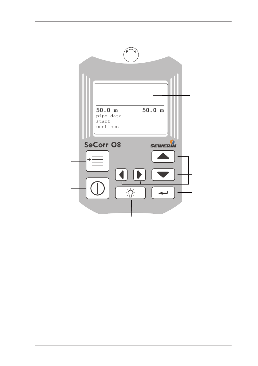
Illustration SeCorr 08
Rotary regulator
Menu key
Central screen
Arrow keys
ON/OFF key
Enter key
Light key
Page 4
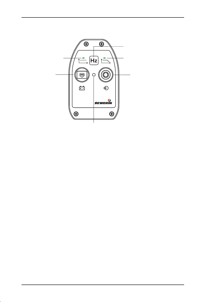
RT 06
A
Hz
A
Hz
Filter key (4)
LED (5), plastic,
low pass
LED (6), metal,
Wideband
Status-LED (1)
Power supply (3)
Microphone connection (2)
Illustration RT 06
Page 5

Operating Instructions
SeCorr® 08
26.04.2010 – V 4.X – 103923 – en
Page 6
Warranty & Used symbols
The following instructions must be complied with in order for any warranty
to be applicable in respect of the functionality and safe operation of this
equipment.
Hermann Sewerin GmbH accepts no liability for any damages resulting
from failure to observe these instructions. The warranty and liability provisions of the terms of sale and delivery of Hermann Sewerin GmbH are not
affected by the information given below.
The product must only be operated after the relevant operating instruc- z
tions have been read and understood.
The product must only be used for its intended purpose. z
The product is only suitable for use in industrial and commercial ap- z
plications.
Repairs must only be carried out by a specialist technician or by other z
suitably trained personnel.
Changes or modications to this product must not be carried out with- z
out approval from Hermann Sewerin GmbH. The manufacturer cannot
be held responsible for damages if non-approved modications have
been made.
All repairs must be carried out using replacement parts that have been z
approved by Hermann Sewerin GmbH.
The manufacturer reserves the right to make technical modications in z
the course of further development.
Generally applicable safety and accident-prevention regulations must be
complied with, in addition to the information provided in this manual.
Used symbols:
CAUTION!
This symbol is used to indicate dangers which may
either result in hazards for the operators or in severe
damage – or even destruction – of the product.
Note:
This symbol is used to call attention to information
and tips which may be helpful and which are exceeding the basic operating procedures.
Page 7

Contents Page
1 Function description ...............................................................1
1.1 Usage ........................................................................................ 1
2 Use ............................................................................................2
2.1 First use ....................................................................................2
2.2 Switching ON/OFF ....................................................................2
2.3 Channel assignment .................................................................3
2.4 Radio transmitter RT 06 ............................................................5
3 Operating elements .................................................................6
3.1 ON/OFF key ..............................................................................6
3.2 Rotary regulator ........................................................................6
3.3 Enter key ...................................................................................7
3.4 Menu key ...................................................................................7
3.5 Left/right arrow keys .................................................................. 7
3.6 Up/down arrow keys ..................................................................7
3.7 Light key .................................................................................... 8
3.8 Adjusting the contrast ................................................................8
4 Performing a correlation measurement ................................9
4.1 Entering pipe data .....................................................................9
4.2 Starting a measurement .......................................................... 10
4.3 Evaluating the result ................................................................ 11
4.3.1 Filtering ................................................................................12
4.3.2 Cursor ..................................................................................12
4.3.3 Zoom ....................................................................................13
4.4 Continuing a measurement .....................................................14
5 Measuring the sound velocity ..............................................15
5.1 General information .................................................................15
5.2 Performing a measurement .....................................................15
6 Charging equipment .............................................................17
6.1 Battery state ............................................................................18
6.2 Charging process/battery maintenance ..................................19
I
Page 8

Contents Page
7 Menu ....................................................................................... 20
7.1 Menu structure ........................................................................20
7.2 Listen .......................................................................................21
7.2.1 AQUAPHON .........................................................................21
7.2.1.1 Display ..............................................................................22
7.2.1.2 Assignment of keys ...........................................................23
7.2.1.3 Sensitivity ..........................................................................23
7.3 File ..........................................................................................23
7.3.1 Store .....................................................................................23
7.3.2 Open ....................................................................................24
7.3.3 Delete ................................................................................... 25
7.4 Filtering ...................................................................................25
7.4.1 Automatic ltering .................................................................25
7.4.2 Manual ltering ..................................................................... 25
7.4.3 Setup .................................................................................... 28
7.4.3.1 Filter limits .........................................................................28
7.4.3.2 Filter basis ......................................................................... 28
7.4.3.3 Filtering method ................................................................29
7.5 Measurement method .............................................................29
7.6 Parameter ...............................................................................29
7.6.1 Noise suppression ................................................................29
7.6.2 Measuring time .....................................................................31
7.6.3 Summation/average .............................................................31
7.6.4 Mode of curve ......................................................................31
7.6.5 Correlation ............................................................................31
7.6.6 Sampling frequency .............................................................32
7.6.7 Table .....................................................................................32
7.6.8 Standard values ...................................................................32
7.7 Components ............................................................................ 33
7.8 Setup ....................................................................................... 34
7.8.1 Date, time ............................................................................. 34
7.8.2 Language .............................................................................34
7.8.3 Radio/cable ..........................................................................34
7.8.4 System .................................................................................34
7.8.5 Name ....................................................................................35
7.8.6 Service .................................................................................35
8 Methods of optimising measuring results .......................... 36
8.1 Changing the number of averaging processes .......................36
8.2 Using lters .............................................................................36
II
Page 9

Contents Page
8.3 Automatic ltering ....................................................................37
8.4 Checking the microphone connections ...................................37
8.5 Using accessories ...................................................................37
8.6 Changing the location .............................................................37
8.7 Saving time .............................................................................37
9 Communication with PC ....................................................... 38
9.1 Requirements .......................................................................... 38
9.2 Software installation ................................................................38
10 Technical data........................................................................40
11 Accessories ...........................................................................41
12 Error messages .....................................................................42
13 Annexe ...................................................................................44
13.1 EC Declarations of Conformity ................................................ 44
Advice on disposal ..................................................................44
13.2
13.3 History of changes ..................................................................45
14 Index ....................................................................................... 46
III
Page 10

1 Function description
1.1 Usage
The correlator SeCorr 08 permits to detect leakage points an
directly buried pressure line systems according to the correlation principle. Sensitive microphones are used to record leakage
noise on accessible installations and ttings. These recordings
are wireless transmitted to the correlator.
SeCorr 08 calculates then the exact leakage position using the
Fast Fourier Transformation (FFT = mathematic algorithm).
Supplementary functions are available to improve e.g., the indication of leaks, to enter several pipe sections or to measure the
sound velocity.
The RT 06 radio transmitter can be used to measure fully auto-
matically the input level of the microphone and to set the level
control of the amplier to the optimum value. Characteristics and
parameters – such as the used microphone type, the charge state
of batteries and the amplier setting – are wireless transmitted to
the correlator for further evaluation.
1 Function description
Note:
These operating instructions are based on software release 4.X, with „X“ standing for any number.
The currently installed software version of your
SeCorr 08 is displayed after switching on the device.
Future releases are subject to change!
1
Page 11
2
2 Use
2 Use
2.1 First use
CAUTION!
Before placing SeCorr 08 and RT 06 for the rst
time into service, make sure that all used batteries
are completely charged. If the batteries are only
partially charged, the capacity of the batteries may
be reduced thus leading to shorter operation.
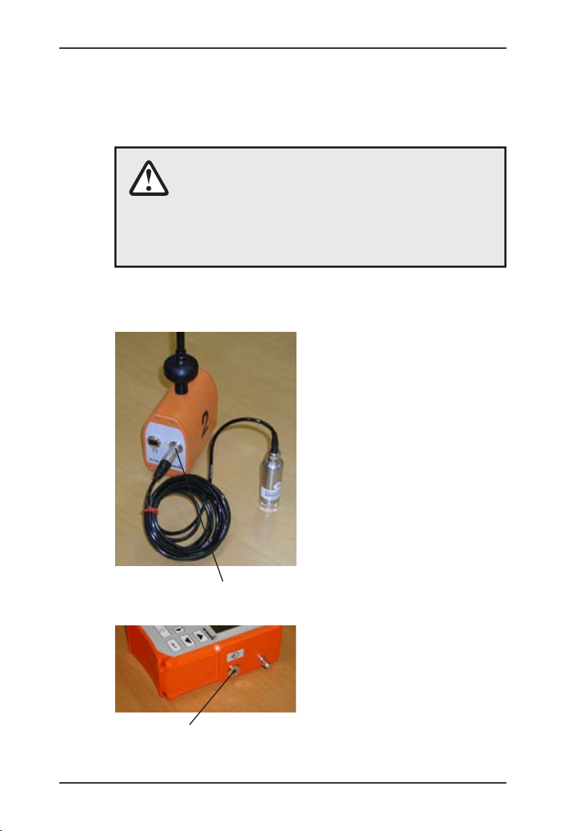
2.2 Switching ON/OFF
1
Position both piezo micro- z
phones at accessible fitting
parts. If the circular magnet
is screwed on the piezo microphone, it may be required
to remove the circular, rmly
adhering protective disk from
the magnet.
Plug both microphone con- z
nectors into the sockets of the
radio transmitter RT 06. If you
want to use only one RT 06, it
is required to connect a micro-
phone directly to input 2 of the
SeCorr 08.
On the RT 06, LED 1 must
be lit.
Connect the headphones to z
socket 3 of the SeCorr 08.
Switch on the SeCorr 08 by z
pressing the ON/OFF key for
a couple of seconds.
2
Page 12
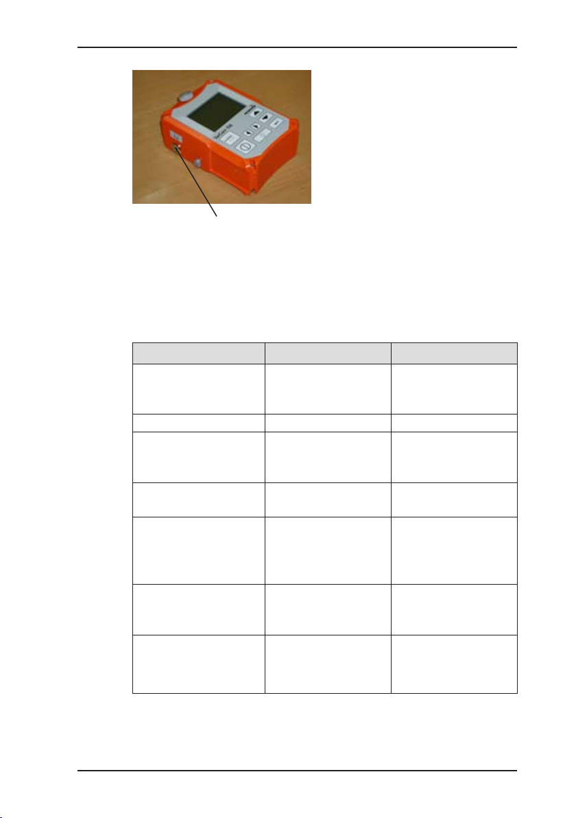
3
3
2.3 Channel assignment
Is indicated together
with message
„battery empty“
Indication Left Right
Type with one signal
channel
Type with two sig-
nal channels
Only one radio
transmitter is used
(e. g. in case of a
defect):
Variant 1 z
(blue radio transmitter in use)
The initial screen is briefly
displayed, containing information on the release number of
the software and the battery
capacity.
Then the central screen appears (see back of cover
page). From this screen, you
ca n acc ess the individual
menus (menu key) or start the
desired functions.
Keep the z ON/OFF key pressed
until the device switches off.
Channel 1 Channel 2
RT 06-1 RT 06-2
Director connection
of microphone to
Radio transmitter 2
(orange)
SeCorr 08
Radio transmitter
1 (blue)
Radio transmitter 1
(blue)
Radio transmitter
2 (orange)
Direct connection
of microphone to
SeCorr 08
2 Use
Variant 2 z
(orange radio
transmitter in use)
Direct connection
of microphone to
SeCorr 08
Radio transmitter 2
(orange)
Page 13
4
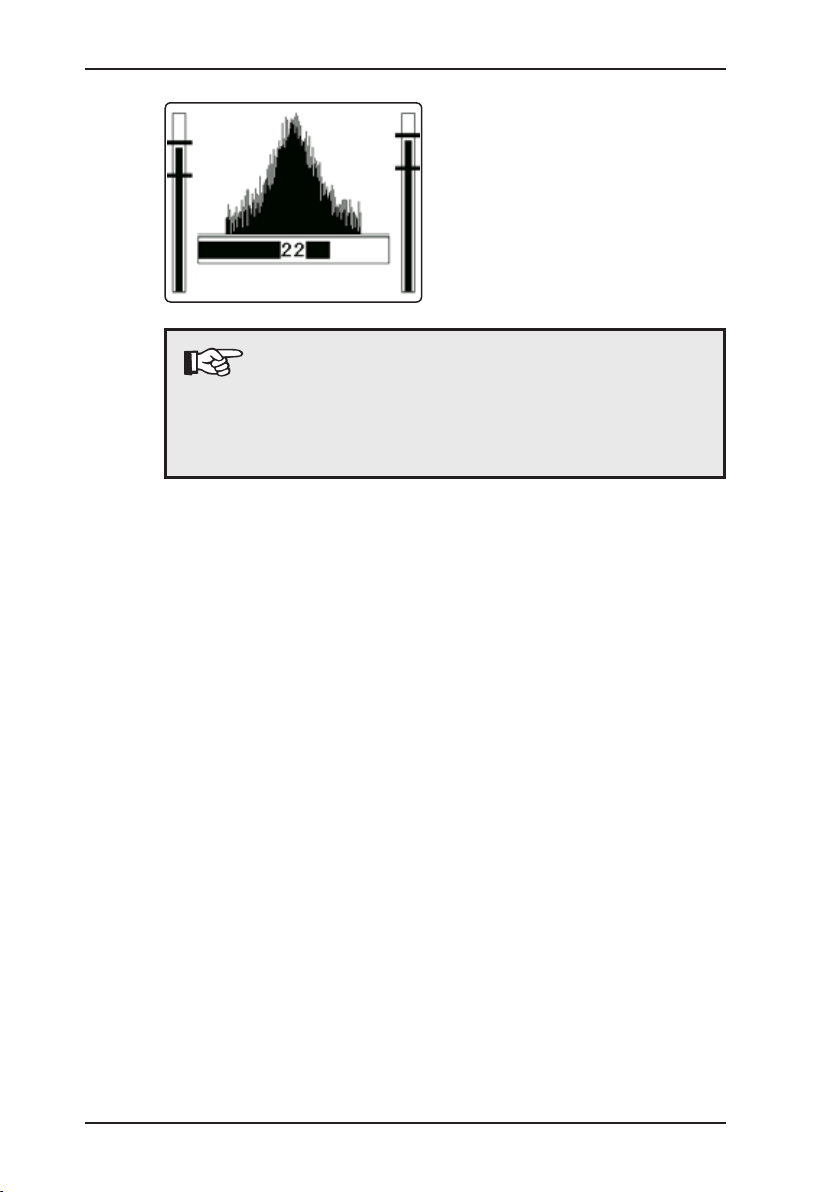
2 Use
During correlation measure- z
ments the noise intensity of
both microphone channels is
indicated to the left- and righthand side of the correlation
function.
started
Note:
The SeCorr 08 version with two transmitters permits
to connect a microphone directly two the SeCorr 08,
e.g., if a radio transmitter is defective (see also section 7.8.3).
Page 14

5
2.4 Radio transmitter RT 06
4
6
3
1
CAUTION!
Connect always rst the sensor to the measurement
location (by coupling the microphone to the slide
valve, hydrant, etc.). Then, switch on the RT 06 by
plugging the sensor into socket 2.
This sequence of steps ensures that the automatic
amplication in the RT 06 is quickly and properly
set.
2 Use
The radio transmitter RT 06
can be operated with different
5
2
sensors, EM30 microphones
and the HA hydrophone.
It is recommended to use the
active lter ZF01, if interfering
noise is to ltered out or if only
a specic acoustic frequency
range is to be transmitted to
the correlator SeCorr 08.
The RT 06 is enabled when the sensor is plugged into socket 2.
Press the lter key 4 generally if plastic pipes are used. The right
LED 5 is lit to indicate the changeover. If this setting is selected,
only the low-pass frequencies are transmitted to the correlator.
This may help to increase the quality of the correlation measurement. If the RT 06 is switched on, all frequencies are always
transmitted; the left LED 6 is lit.
The transport handle on top of the antenna can be used for car-
rying the device.
LED 1 shows the state of the RT 06:
Operation: green
Undervoltage: ashed red
Charging: 1 x ashing green
Buffering: 2 x ashing green
No charging: red (because temperature below 0 °C)
Page 15

6
3 Operating elements
3 Operating elements
3.1 ON/OFF key
Press this key to switch the device on or off. Hold it pressed until the SeCorr 08 is activated.
If the key is pressed only shortly,
the currently running function is
stopped (e.g., a correlation in
progress). If you have opened
the menu, you can use the ON/
OFF key to return to the next
higher menu level. Press the key
only shortly.
If a correlation is stopped, the
diagram (correlation function)
can be zoomed in. If any key is
pressed, the display returns to
normal representation.
3.2 Rotary regulator
Turn the Rotary regulator to
move the selection or the cursor
to the left/right or up/down.
You can use the Rotary regulator
to change values in numerical
entry elds (e.g., pipe length).
Press the Rotary regulator once
to change the direction of movement from up/down to left/right or
vice versa.Pressing the Rotary
regulator has the same effect as
pressing the Enter key.
Page 16
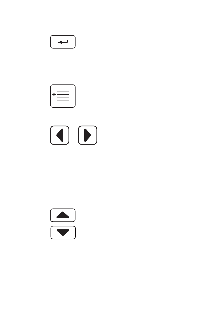
7
3.3 Enter key
3.4 Menu key
3.5 Left/right arrow keys
3 Operating elements
Press this key to enable the currently selected function.If you
select „Cancel“ in the menu, the
display returns to the central
screen.
Press this key to open the menu
(see section 7).
Press these keys to move to the
left or right within the selected
function. In some menus the
arrow keys can also be used for
selecting options.
You can access the next higher
menu level by pressing the left
arrow key. You can use this function only if the cursor is set to its
left or right end position.
3.6 Up/down arrow keys
Press these keys to move the
cursor up or down in a menu.
In some menus the Arrow keys
can also be used for selecting
options.
Page 17
8
3 Operating elements
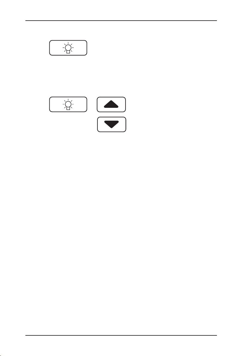
3.7 Light key
3.8 Adjusting the contrast
Use this key to switch the illumination on or off. The illumination automatically switches off after a pre-set period
(see section 7.8.4).
The contrast of the display is au-
tomatically controlled in relation
to the temperature.
You can ad just the contrast
manually by holding the Light
key pressed while operating the
Up or Down Arrow key at the
same time.
Page 18

9
4 Performing a correlation measurement
4 Performing a correlation measurement
4.1 Entering pipe data
Before starting a measurement, it is required to enter the pipe
data.
Select option pipe data using z
the Arrow keys and conrm
your selection with the Enter
key.Then, enter the number of
pipe sections.
Depending on the type of ap- z
plication, select One, Two or
Three pipe sections with the
arrow keys. Conrm your selection with the Enter key.
Enter the pipe length. Use z
the left or right arrow key to
change between the displayed
digits.
You can use the Up/Down z
arrow keys to increase or
reduce the displayed value in
increments.
Confirm the length with the z
Enter key.
In the list, select the material z
of the pipe section using the
Arrow keys. You can also use
the direct option to enter the
sound velocity manually.
Pay attention to the following: z
The values in the list are ap-
proximate values and may be
subject to inaccuracies (see
section 5.)
In the displayed list, select the z
pipe diameter using Arrow keys.
Page 19

10
4 Performing a correlation measurement
Start
cancel
100.0 m
steel
125 mm
1280 m/s
Note:
Apart from the default application, „Cross cor-
relation“, SeCorr 08 can also be used to perform
automatic correlations („Auto correlation“); refer to
chapter 7.6.5!
4.2 Starting a measurement
Select this function, if a measurement section is measured for
the rst time or if an error occurred during the rst measurement
(transmitter is not switched on, problems during connecting the
microphone, etc.).
pipe data
start
continue
If necessary, repeat these en- z
tries for the second and third
pipe section.
Select start with the Arrow z
keys and conrm your selection with the Enter key.
Use the headphones to check
the measurement trend acous-
tically (safety instructions: see
section 7.2.1).
A summary of the entered z pipe
data appears on the screen.
Select Start with the Arrow
keys. Press the Enter key.
The correlation measurement
starts.
Page 20

11
pipe data
start
continue
4 Performing a correlation measurement
Press Cancel to return to the z
main menu.
Depending on the selected
settings (see section 7.6.2)
either 16, 32, 64 or 128 averaging processes (i.e., measurements) are performed.
The display shows the current-
ly performed measurement.
During the measurement, the
correlation function is continuously updated.
The correlation measurement z
can be interrupted any time
by pressing the ON/OFF key
shortly.
An interrupted measurement
can always be resumed.
After the z measurement the re-
sult is displayed. The adjacent
illustration shows a correlation
example. The method of display depends on the setting
selected in the „Filter / Setup“
menu.
4.3 Evaluating the result
pipe data
start
continue
The correlation function uses
peaks to indicate where a leak
may be located. The time-delay
difference is displayed on the x
axis in ms (i.e., milliseconds).
The highest peak is automati-
cally highlighted.
Page 21

12
4 Performing a correlation measurement
CAUTION!
If a peak is displayed right in the centre of the screen,
this may indicate that the RT 06 radio transmitter is
placed too close to the SeCorr 08 (receiver). In this
case, increase the distance (5 – 10 m).
4.3.1 Filtering
Please read section 7.4 and 7.4.2 on the basic principles of ltering.
The ltering option here from the function in the main screen offers faster access to manual functioning than via Menu / Filter /
Manual. The range of functions here is, however, limited.
Select “Filter“ in the main screen. z
The left lter limit ashes and can be set. z
Enter key: calculates the result function; the other lter limit can z
be set (can be repeated as often as you wish).
ON key: returns to the main screen, the result is displayed. z
4.3.2 Cursor
After selecting the Cursor function with the Arrow keys, you
can move the cursor to any
position using the Arrow keys
or Rotary regulator.
Depending on the highlighted
position, the measurement result
is immediately recalculated. The
time indicated next to the cursor
represents the set time-delay
difference.
Below the correlation function,
the distance between the current cursor position and the two
microphones is displayed.
Page 22

13
4.3.3 Zoom
cursor
zoom
zoom
menue
4 Performing a correlation measurement
Use the Zoom function to zoom
in any area of the correlation
function.
Select zoom with the z Arrow
keys.
Zoom in the display by press- z
ing the right Arrow key. The
position bar 1 below the corre-
lation function indicates which
part of the total pipe length is
zoomed in.
Press the left Arrow key to re- z
turn to the display of the complete correlation function.
Note:
If the correlation procedure is used, subjectively
assessing the form of the correlation function may
be signicant. The experience required for this
cannot be taken from books – only practice makes
perfect.
The result of the measurement is based on the value
marked in the CCF and on the entered pipe data.
In simple terms, the correlation function represents
– qualitatively and chronologically – the relation
between the two noise signals that were recorded
by both microphones.
It is generally not possible to distinguish between
leakage noise (that is the noise that we are looking
for) and other background noise. For this reason,
the measurement result does not always represent
a leakage point; background noise can also be the
cause!
If no specic noise signal is present, the measurement result may be arbitrary. In this case, you should
use positions with more distinct leakage noises for
connecting the microphones.
Page 23

14
4 Performing a correlation measurement
4.4 Continuing a measurement
This function starts the correlation measurement using the available pipe data. The results obtained remain stored (e.g., from a
previously performed correlation).
Pipe data changed after the last correlation is not used.
It is recommended to continue the measurement, if the result of
the rst measurement (e.g., number of averaging processes: 32)
is not completely reliable.
pipe data
start
continue
Select continue with the Ar- z
row keys and conrm with the
Enter key.
Perform the measurement as
described in section „Starting
a measurement“.
Page 24

15
5 Measuring the sound velocity
5 Measuring the sound velocity
5.1 General information
It is required to measure the sound velocity since only correctly
entered sound velocity values ensure precise measurements.
The sound velocity values are taken from an internal table, see
section 7.6.7. However, the sound velocity values entered under
Pipe data are only approximate values. Apart from that, it may
also be possible that you do not know the pipe dimensions or
material.
This function requires a noise source:
You can use an opened hydrant, for example, z
which generates a clear display in the correlation-function eld, z
thus being „correlatable“,
whose location must be known, z
whose location should not lie in the central range of the mea- z
surement section, in order to increase the measuring precision.
If the measurement section consists of varying pipe sections (different materials or dimensions), the sound velocity measurement
will lead to incorrect results.
5.2 Performing a measurement
The measurement procedure is very similar to that of correlation
measurements.
First, connect microphones and z radio transmitter as described
in section 2.2).
Enable option Sound velocity in z menu Measurement method
(see section 7.5).
Select Pipe data and enter the corresponding data. z
Under Articial leak, enter the distance between the articial z
leak and microphone 1: if it lies outside and beyond the mea-
surement section
of microphone 1, enter 0 m as distance, –
of microphone 2, enter the entire length of the measurement –
section under distance (i.e., the „pipe length“).
Page 25

16
5 Measuring the sound velocity
Create an articial leak to generate a noise source (e.g., opened z
hydrant) or take a hammer and beat rapidly on the tting.
Select Start with the Arrow keys. z
The measurement procedure begins.
After the z measurement the correlation function is displayed
on screen.
The cursor is automatically set to the position with the largest z
value. Check whether this position corresponds to your articial
leak. If require, move the cursor with the arrow keys or Rotary
regulator to the articial leak.
If you select Input in the menu: z
The determined sound velocity is loaded into the internal –
memory.
The measurement method „Measure sound velocity“ is exited –
(reset to „standard“ method).
The central screen is called up. –
You can now perform a correlation measurement for determining the real leak. When entering pipe data which may require
modifying, it is recommended that you also enter the determined
sound velocity. Select the item „Direct“ under ”Pipe material”
for this.
If you select ”Cancel” in the z menu:
the determined – sound velocity will not be accepted.
the – measurement method “Measure sound velocity” is exited
(reset to “Standard” method).
The central screen is called up. –
Page 26

17
6 Charging equipment
1
6 Charging equipment
Built-in NiMH cells are used for
supplying the SeCorr 08 and
RT 06.
The ope r a t i o n time of the
SeCorr 08 is approx. 8 hours. If
the display illumination is used
or if the outside temperature is
low (so that the display heater is
switched on), the operation time
can be signicantly shorter.
The operation time of the ra-
dio transmitter RT 06 is min.
8 hours.
Optionally (if the battery is empty) the SeCorr 08 and the radio
transmitter RT 06 can be operat-
ed with an external 12 V = power
source (e.g. vehicle cable).
If the devices are to be charged
or operated externally, either the
docking station HS 1,2 A with
the AC/DC adapter or the vehicle
cable is required. Charging the
SeCorr 08 takes max. 4 hours.
Charging the radio transmitter
RT 06 takes max. 5 hours.
Connect the vehicle cable to
socket 1 on the docking station
or to socket 3 on the transmitter
RT 06.
3
Page 27

18
6 Charging equipment
The SeCorr 08 and the RT 06
transmitters can also be charged
when put into transport case.
To do this, connect vehicle cable
or AC/DC adapter to socket 1 in
the case.
1
Inside the transport case, connect
cables 2 and 4 to the two RT 06
transmitters and cable 3 to the
docking station HS 1,2 A.
2 3 4
6.1 Battery state
The battery state is indicated on the SeCorr 08 display by a bat-
tery icon together with the following messages:
RT 06-1 z or RT 06-2 or SeCorr 08
Battery icon and message appear when the operation time of the
corresponding component is less than 15 minutes.
More details are indicated by the status LED on the RT 06, see
also section 2.4.
Page 28

19
6.2 Charging process/battery maintenance
During charging, the SeCorr 08 displays a number indicating the
remaining charging time in hours. In this mode, you can select
the function Battery maintenance using the menu key. With this
function, the battery is rst discharged and then recharged. This
ensures that chemical deposits inside the battery are removed
and that the memory capacity of the battery is improved. The
process takes approx. 10 hours. It is recommended to use this
function regularly (in cycles of 60 days) for devices which are
only rarely used.
Symbols and their meaning during the charging process:
Battery maintenance is enabled.
The temperature has dropped
below 0 °C, the battery cannot
be charged.
6 Charging equipment
The temperature has exceeded
45 °C, the battery cannot be
charged.
Page 29

20
7 Menu
Listen
Channel 1
Channel 2
Channel 1 and 2
AQUAPHON
File
Open
Low resolution
High resolution
Noise
Store
... see „Open“
Delete/All
... see „Open“
Filtering
Automatic
Manuel (**)
Setup (*), (**)
Filter limit
Filter basis
Coherence
Cross spectrum
Spectrum KA 1
Spectrum KA 2
Filtering method
Rectangle
Hanning
Measuring method
Standard
Sound velocity
Parameter
Noise suppression
Automatic
Manuel
Off
Measuring time
Standard =32
Summation/Average
Summation
Averaging
Mode of curve (*)
CCF positive
CCF pos. + neg
TOP pos. + neg.
Type of correlation
Cross correlation
Auto Corr. CH 1
Auto Corr. CH 2
Sampling frequency
Automatic
Manuel
Table (*)
Standard values
Components
Setup (*)
Date, Time
Language
Radio/Cable
System
Name
Service
7 Menu
7.1 Menu structure
(*) Settings which remain stored
after switching off the device.
All other settings are reset to
the respective standard val-
ues (see section 7.6.8).
(**) This menu and the corre-
sponding functionality is only
available in the professional
version.
Page 30

21
Note:
Certain menu items are not available in the standard
version. If you select an item which is not available,
an appropriate message is indicated. If you want to
upgrade from the standard version to the professional version, a registration code is needed.
7.2 Listen
Use the Listen function to set the sound level of both channels.
Select the channel which you want to change with the arrow z
keys.
You can then change the sound level of he selected channel z
using the arrow keys or Rotary regulator.
If you select z „Channel 1“, you will hear channel 1 on both ears
(mono mode). The same applies to „Channel 2“. If you select
„Channel 1 and 2“, you will hear both channels at the same
time (stereo mode).
7.2.1 AQUAPHON
Use the “Aquaphon” function to enable the integrated feature
for searching leaks. This feature can be compared to that of the
Sewerin AQUAPHON A 100 / AF 100 device. These devices, how-
ever, are provided with a considerably wider range of functions.
You can use the microphones of this system.
The maximum measured value can be measured in the vicinity
of the leak.
Select the menu option Correlator to return to the correlator
mode.
To switch off the device:
pull the microphone connector from the socket (otherwise the –
device is switched on again and again)
enable the Correlator menu item (this permits to save the modi- –
ed settings for sensitivity and sound volume)
press the ON/OFF button. –
7 Menu
Page 31

22
7 Menu
Note:
You can access the Aquaphon mode directly by
connecting a suitable microphone to the disabled
device (power OFF).
CAUTION!
Do not use the headphones with high volume. Audiologists warn that the exposure to persistent or
sustained noise may result in hearing defects.
Set the volume to an appropriate level. z
Switch off the headphones when you suspect that z
interfering noise may occur (pedestrians, cars,
etc.).
Switch off the headphones before moving the z
microphone.
Bear in mind that your perception capability is z
reduced.
7.2.1.1 Display
The display contains the following components:
sensitivity
correlator
Measured value (sound level at microphone)
Set sensitivity
Headphones volume
Filter settings
Detected microphone type
Page 32

23
7.2.1.2 Assignment of keys
In the Aquaphon mode, the key assignment of the SeCorr 08
differs from the standard mode.
7.2.1.3 Sensitivity
Use the Sensitivity option to set the basic amplication of the
leakage noise.
You can select the following levels
sensitive z (display range 10)
medium z (display range 100)
insensitive z (display range 1000)
7 Menu
Switch ON/OFF the headphones.
Turn the Rotary regulator to set
the volume of the headphones.
The headphones are switched
on as long as you press on the
Rotary regulator.
Use the ON/OFF key to change
the sensitivity level (see section
below).
7.3 File
In this menu, you can open, save and delete individual measure-
ments. The professional version also permits to open, save and
delete sound samples. The data is led in the internal storage
of the SeCorr 08 and can be called up even after switching off
the device.
7.3.1 Store
The following number of storage locations is available:
a) 50 storage locations (low resolution)
b) 25 (1 – 25) storage locations (high resolution)
c) 5 (1 – 5) storage locations (sound)
Page 33

24
7 Menu
Note:
b) and c) share a common storage area.
Measurements which were stored with a low resolution cannot
be post-post-processed (e.g., ltered) at a later date. Only the
central screen can be called up for viewing.
Functions: View of the central screen,
cursor navigation,
starting, continuing.
50 storage locations with low resolution are available.
Measurements which were stored with a high resolution can be
post-processed at a later date. This means that all functions which
are usually possible after closing (i.e., stopping) a measurement,
are also possible in this situation. Exception: It is not possible to
„continue“ the measurement.
Up to 25 storage locations are available. These locations are
shared with the „sound“ storage.
If you select Noise, the currently measured noise is stored for
approx. 7 seconds.
Pay attention to the following: Saving takes approx. 35 seconds
due to the high memory capacity. The process cannot be inter-
rupted.
Use the arrow keys to select the item which you want to save: z
Low resolution, High resolution or Noise.
After conrming with Enter, the measurement or noise signal z
is saved.
7.3.2 Open
Use the arrow keys to select the item which you want to
open:
Low resolution, High resolution or Noise. Please note that it z
takes approx. 25 seconds to load a sound.
Conrm your selection with the Enter key.
A list is displayed including all les of the SeCorr 08 memory.
Page 34

25
Select a le with the Arrow keys and conrm your selection z
with the Enter key.
If you have opened a measurement, it will then be displayed. z
If you have opened a noise signal, the noise will be played back
with a phasic duration of 7 seconds. You can cancel the playback
by shortly pressing on the ON/OFF key.
7.3.3 Delete
Use the Arrow keys to select the item which you want to z delete:
low resolution, high resolution or noise. Conrm your selection
with the Enter key. A list is displayed including all les of the
SeCorr 08 memory.
Select the le which you want to delete with the Arrow keys z
and conrm your selection with the Enter key. The le is then
deleted.
7.4 Filtering
You can use the ltering function to cut off certain frequencies from
the correlation function, thus leading to improved results.
You can select between manual or automatic ltering.
7 Menu
7.4.1 Automaticltering
After a measurement, SeCorr 08 performs an automatic lter run
(post-processing). During this procedure the lters are automati-
cally optimised.
7.4.2 Manualltering
An image is generated in which you can see a frequency trend
(lter base at the bottom of the image, see chapter 7.4.3.3), as
well as the result based on the set lters (representation, see
chapter 7.6.4).
Page 35

26
7 Menu
Press the Enter key to change to
the editing mode.
Use the Arrow keys to select z
the filtering limit which you
want to change:
- Filter left
- Filter right
- Cut off left
- Cut off right
Use the arrow keys to shift the z
corresponding limit.
The appropriate frequency is
displayed on screen.
Light grey frequency ranges
are cut off.
Ranges which are indicated
in black are used for correlation.
If you want to zoom in the
frequency range, you need
to change the set filter lim-
its beforehand (see chapter
7.4.3.1).
Page 36

27
zoom
filter left
filter right
cut off left
7 Menu
left
ltering limit
cut off limit
left
right
ltering limit
right
cut off limit
Select “OK” with the Arrow z
keys.
The set lters are applied and
the indicated frequency trend
is updated together with the
result.
Press the z Enter key to return
to the direct ltering screen to
redene other lter limits, if
necessary.
Select “Return” to return to the z
central screen and to store the
changed settings.
Page 37

28
7 Menu
7.4.3 Setup
Customized settings are saved in the setup, sparing users the task
of calling up the desired functions every time they are required.
Place the cursor on the desired item and press the Enter key.
7.4.3.1 Filter limits
Use this setting to dene the lter settings to be used for manual
ltering (see chapter 7.4.3.1).
Default setting: If you enter a sound velocity for a measurement
which is lower or higher than 700 m/s, the correlator uses the
following values:
Lower limit / Hz Upper limit / Hz
< 700 m/s 5 500 Synthetic material / plastic
> 700 m/s 0 3000 Metal
It plays no role whether the sound velocity is manually entered or
whether appropriate pipe parameters are selected.
7.4.3.2 Filter basis
You can use this menu option to change how the frequency curve
of the lter setting is represented.
Coherence z
This function is used to indicate similar frequencies.
Cross spectrum z
This function is used to indicate the cross spectrum of both
channels.
Spectrum, CH 1 z
Used to indicate the frequency spectrum of channel 1.
Spectrum, CH 2 z
Used to indicate the frequency spectrum of channel 2.
Page 38

29
7.4.3.3 Filtering method
If rectangle is selected, signal ltering is performed precisely at
the marked point.
With Hanning, the range of the marked point is faded in with soft
transitions.
7.5 Measurement method
You can use the measurement method function to change be-
tween standard measurement (= correlation measurement) and
sound velocity measurement (see section 5).
7.6 Parameter
Use the parameter sub-menus to set parameters which are having effect on the measurement.
7.6.1 Noise suppression
The noise suppression function can be used for reducing the negative effect of temporary interferences (vehicles, pedestrians).
If the noise suppression function is enabled, it is assumed that
optimum results can be achieved in those moments in which the
measured noise (signal) is relatively low. This means that the permanently present leakage noise is preponderantly undisturbed.
In moments in which the signal is relatively loud, the additional
noise must come from a interference source in all probability,
leading to much less reliable measurement results.
The level range is limited by the upper threshold and the lower
threshold. During a running measurement, these thresholds for
signal 1 and 2 are indicated as horizontal lines on the left or right
edge of the display.
After a dened interval, the level range is automatically and slowly
increased, if the current level values lie permanently above the
level range. In the same way the level range is reduced, if the
current level values lie permanently below the level range.
7 Menu
Page 39

30
7 Menu
a) Automatic mode (Default setting)
This setting is recommended for standard situations and ensures
reliable results.
After a dened interval, the level range is automatically and slowly
increased, if the current level values lie permanently above the
level range. In the same way the level range is reduced, if the
current level values lie permanently below the level range.
b) Manual mode
This setting is recommended, if you want to work with maximum
interference suppression and if you desire greatest possible in-
uencing control for measurements.
If the interruption is too long due to excess noise, it is possible
to manually increase the level range with Continue, so that the
sensitivity level is reduced. The measurement is continued with
the operator ignoring a certain level of interfering noise.
If the current level values fall below the level range, an adjustment is automatically performed, i.e., the correlator is set to a
more sensitive level.
c) Off
It is recommended to select this setting only in situations which are
marked by frequently returning, strongly varying signals resulting
in the measurement being frequently interrupted, thus preventing
a correlation completely.
Noise suppression is disabled. With this setting, it is accepted
that interfering noise is jamming the leakage noise from time to
time.
Page 40

31
7.6.2 Measuring time
You can use the Measuring time function to dene how many indi-
vidual measurements are to be performed until the measurement
sequence is stopped.
7.6.3 Summation/average
With the „Summation“ function all individual results are used for
representing the CCF. This representation is immediately used.
If you select „Average“, the individual results are evaluated using
a different procedure: The last performed measurement has the
largest inuence on the CCF. The preceding measurement has
less inuence, etc.
This procedure ensures that the CCF, with selected Average,
represents the current noise situation.
7.6.4 Mode of curve
You can change the mode how the correlation function is repre-
sented as follows:
CCF positive z
The CCF has only positive values.
CCF pos. + neg. z
The CCF contains positive and negative values.
TOP positive z
The representation is similar to that of CCF positive. Peaks,
however, are represented more signicantly in most cases.
TOP pos. + neg. z
The representation is similar to that of CCF pos. + neg. Peaks,
however, are represented more signicantly in most cases.
7 Menu
7.6.5 Correlation
If Cross correlation is selected, the noise source to be located
must lie within the measurement section. The measurement is
carried out with both channels (1 and 2).
With Auto correlation, either channel 1 or channel 2 is used. The
second signal required for the correlation is created by the noise
reection which is detected at the reection point. It is required
that the signal is received by the channel which is to be used.
Page 41

32
7 Menu
Since the energy of the reected noise signals is generally extremely low, it is recommended to use this procedure only in special
cases. If the pipe contains gases, the chances may be better.
If Auto correlation is used, the location of the reection point must
be known.
The auto correlation function (ACF) always runs symmetrically. Only
the negative range of the auto correlation (delta t < 0) is signicant.
7.6.6 Sampling frequency
The continuous time signal of the used channels is sampled and
digitised with a particular frequency, the sampling frequency.
The lower the sampling frequency, the less time is required for calculating the averaging processes. However, the used sampling theorem
demands a sampling frequency which is at least twice as high as the
highest frequency contained in the signal! Setting the sampling frequency too low may lead to faulty measurements. For this reason, it
is recommended to decrease the sampling frequency only in special
cases, e.g., if extreme low-frequency noise is to be measured.
If Automatic is selected, the sampling frequency is set to its maximum height.
If you want to dene the setting manually, select Direct. You can
then change the sampling frequency with the arrow keys.
All following measurements are performed with this sampling
frequency.
7.6.7 Table
In this menu, you can select two different sound velocity tables.
They differ in subranges.
Sound velocity 1: Particularly good experiences in France
Sound velocity 2: International validity
Sound velocity 3: This function is not available
7.6.8 Standard values
All parameters in the Parameter menu of the SeCorr 08 are re-
set to the respective standard values. This also includes those
parameters which remain stored after switching off the device.
The set language is not changed.
Page 42

33
7.7 Components
The screen shows an overview of the most important information
on the max. 3 main components of the system (2 RT 06 devices,
1 SeCorr 08 correlator).
7 Menu
Symbol explanation
Battery empty
Low volume High volume
Bad signal
reception
Battery fully
charged
Good signal
reception
Page 43

34
7 Menu
7.8 Setup
7.8.1 Date, time
Use this option to set the current date and time. You can also
select the date format.
7.8.2 Language
Use this option to select the desired language.
7.8.3 Radio/cable
Use this option to dene which channel is to be operated with
radio transmission and which channel is to be directly connected
to the SeCorr 08.
Use the Arrow keys to select the channel which you want to z
change. Conrm your selection with the Enter key.
Use the Arrow keys to toggle between RT 06-X and SeCorr 08, z
with RT 06 standing for radio transmission and SeCorr 08 for
cable operation. Conrm your selection with the Enter key.
Note:
If „American English“ is selected, several productspecic units of measurement will change.
For example:
Distance feet (ft), z
Diameter inch (in) z
Velocity feet per second (ft/s) z
7.8.4 System
You can use this option for:
Setting the time at which the light is to be z switched off auto-
matically.
Setting the time at which the device is to be switched off au- z
tomatically.
Page 44

35
7.8.5 Name
This option is used for entering name, company and address.
7.8.6 Service
This menu option is reserved for the Sewerin service.
7 Menu
Page 45

36
8 Methods of optimising measuring results
8 Methods of optimising measuring results
The location is based on the correct determination of the timedelay difference. If the leakage noise is sufciently loud and if
there are no background noise sources, the time-delay difference is adequately well-displayed after only a few averaging
processes (4 to 16).
But what can be done if no sufciently clear peak can be generated? The following instructions cannot substitute practice and
experience still required in difcult situations. However, they will
help you to learn the basic operations.
Be that as it may, you must always remember one thing: If the
leakage noise does not reach the microphones with sufcient
intensity, no correlation is possible!
8.1 Changing the number of averaging processes
If a result is unsatisfactory after the initial series of averaging proc-
esses, you can improve it by increasing the number of cycles. The
result is improved because the calculation is based on a greater
body of information on the chronological behaviour of the leakage
noise. However, experience has shown that the result can only
rarely be additionally improved if more than 64 to 128 averaging
processes are selected.
8.2 Usinglters
Use the features made available by the mathematical lters.
Unfortunately it is hardly possible to give any generally valid
„formula“. Only your own experience, i.e., learning by doing, will
lead to success.
In most cases, it is only practical to select frequency ranges for
the correlation function in which the coherence function does
clearly stand out from its environment, i.e., where there is peak.
Individual frequencies from various interference sources generate
a uniformly sinusoidal correlation function. They can be recognised in the spectra as sharp lines.
Page 46

37
8 Methods of optimising measuring results
8.3 Automaticltering
The SeCorr 08 can perform an automatic lter run (post-process-
ing) after a measurement (see chapter 7.4.1). This procedure is
used to optimise the lters of the coherence function with the
help of statistical methods. This permits to obtain optimum cor-
relation results.
You may perform an automatic frequency analysis for both, running measurements or already stored measurements.
8.4 Checking the microphone connections
Make sure that the microphones are rmly and securely plugged
into their sockets. Remove any dirt or rust.
8.5 Using accessories
Use Sewerin accessories and auxiliary equipment. Use a hydrophone for plastic pipes. The active lter makes additional features available. You can use the „teach yourself“ tape to check
the system and to keep your level of knowledge up-to-date with
a minimum of effort.
8.6 Changing the location
Use a different location for positioning the microphones. Even
remote locations can generate better results if the sound transmission is improved.
8.7 Saving time
If it turns out during a measurement that it is not possible to record
a peak, all run-up efforts to collect precise data on the pipe were
in vain. Practice has shown that it might be better to start the
measurement with estimated pipe data. If it turns out that the
assumed pipe length is greater and/or the sound velocity lower
than expected, a possible peak will appear in any case within the
correlation function – which simply cannot be „overlooked“.
Also with this more practice-oriented approach, it is still required
to determine the pipe data precisely.
Page 47

38
9 Communication with PC
9 Communication with PC
It is possible to transmit measurements to a PC which are stored
with high resolution in SeCorr 08. These les can be archived and
post-processed on computer (e.g., to set up a protocol). In addition, it is possible to print out data and graphics, provided that a
printer is available. The stored „sound“ as well as measurements
with low resolution cannot be transmitted.
9.1 Requirements
PC (operating system: Windows 95 / 98 / 2000 or XP)
Program “SeCorr 05” (PC correlator software), from version 10.16
onwards (15.1.2003)
SeCorr 08 Professional version
9.2 Software installation
Install the SeCorr 05 software (demo version on CD) on the
PC.
Connection of all cables and connectors: –
Connect any serial interface of the PC to the SeCorr 08 (socket
with cap at the left-hand side of the device). Use the communication cable (accessory) for this. The PC must not be congured
to an interface higher than COM 4.
Put the – SeCorr 08 into the HSM docking station which is sup-
plied with 12 V=. It plays no role whether the SeCorr 08 is
switched on or off.
Transmitting data from – SeCorr 08:
Start the SeCorr 05 program and select function SeCorr 08 in
the File menu.
The data is transmitted, converted and stored in the „SeCorr 08“
target directory. Depending on the extent and number of measurements this process may take some time. The progress of
transmission is indicated on the computer. The SeCorr 08 target
directory is generated in the working directory from which the
SeCorr 05 program was started, e.g., C:\CORWI.
Page 48

39
9 Communication with PC
The le names are automatically generated using the measuring
date and the measurement time in SeCorr 08 (which is precise
to the minute). They have the following format:
HA_DD-MM-YYYY_HH-MM.COR
with:
DD-MM-YYYY = Date (day, month, year)
HH-MM = Time (hour, minute)
The les can be managed (e.g., renamed, moved) just as any
other le.
Opening measurements –
In the SeCorr 05 program, you can open measurements with File
Open le. You can nd more detailed information on how to use
SeCorr 05 in the program’s help menu.
Page 49

40
10 Technical data
10 Technical data
Correlator SeCorr 08
Operation time: approx. 8 hours
Operating temperature: -10 °C – +40 °C
Storage temperature: -20 °C – +60 °C
Charging time: 4 hours
Weight: 1.3 kg
Protection class: IP65
Dimensions
(W × H × D):
Radio transmitter RT 06
Signal transmission: 500 mW
Charging time: 5 hours
Operating time: 10 hours
Filter setting – wideband: 0 – 3000 Hz
Filter setting – low-pass: 0 – 300 Hz
Weight: 1.3 kg
Dimensions
(W × H × D):
Protection class: IP67
125 × 180 × 65 mm
73 × 190 × 125 mm
(with antenna = 510 mm )
Page 50

41
11 Accessories
Communication cable between PC (COM interface)
Carrying case with foam inset for the correct
Hydrophone type HA e.g., for connection to inhouse
Hydrophone adapter UFH
DN 80 for 1“ female threads
Adapter for main pipes M10 for the permanent coupling of a
Adapter for in-house
connection M10
Piezo microphone EM30 non-corrosive version
Activelter for suppressing interferences
Test-and-teach-yourself tape cables incl.
Test-and-teach-yourself CD cables incl.
11 Accessories
and SeCorr 08 correlator.
arrangement of correlator, radio
transmitter, microphones and
head phones.
PE pipes after dismounting the
water meter.
between ground hydrant and
hydrophone type HA.
microphone to a slide valve or
hydrant.
for the permanent coupling of a
microphone to an in-house cutoff valve.
Page 51

42
12 Error messages
12 Error messages
Error code Cause
Radio! RT 06-1 This message may appear if a correlation
measurement is to be started. It is used to
warn the operator. It is nevertheless possible to perform a correlation measurement.
However, the quality of the radio transmission may be worse.
This error message appears when:
the z radio transmitter is not operated,
the transmission is impaired by buildings, z
etc. between SeCorr 08 and RT 06,
the distance between z SeCorr 08 and
RT 06 is too large.
Remedy:
Check the corresponding radio transmit- z
ters. Are they really switched on?
Position the radio transmitter in such a z
way that the signal route between transmitter and correlator is as good as pos-
sible (line-of-sight between transmitter
and receiver).
Check the radio transmission with the z
headphones. Can you hear any distinct
(leakage) signals or only noise?
Radio! RT 06-2 see „Radio! RT 06-1“
Microphone!
no microphone connected z
Channel 1
Channel 1
(resp. 2)
automatic amplier is being readjusted z
(simultaneous display of a bar graph
showing the progress)
Page 52

43
Error code Cause
F200 Communication error
Error F200 can be ignored if they appear
only occasionally. If they appear frequently,
contact the SEWERIN service..
F201 Communication error
Error F201 can be ignored if they appear
only occasionally. If they appear frequently,
contact the SEWERIN service..
Note:
If further error codes are indicated, please contact
the SEWERIN service!
12 Error messages
Page 53

44
13 Annexe
13 Annexe
13.1 EC Declarations of Conformity
Hermann Sewerin GmbH hereby declares that the SeCorr 08
fulls the requirements of the following guidelines:
2004/108/EC
z
The transmitter RT 06 fulls the requirements of the following
guidelines:
1999/5/EC
z
The complete declarations of conformity can be found online
(www.sewerin.com > Downloads).
Advice on disposal
13.2
The European Waste Catalogue (EWC) governs the disposal of
appliances and accessories.
Description of waste Allocated EWC waste code
Device 16 02 13
Disposable battery, rechargea-
ble battery
16 06 05
End-of-life equipment
Used equipment can be returned to Hermann Sewerin GmbH. We
will arrange for the equipment to be disposed of appropriately by
certied specialist contractors free of charge.
Page 54

45
13.3 History of changes
Version Description Date
13 Annexe
4.0 Additional function available in central z
screen: ltering. It performs a faster and
simplied access to manual ltering
3.0 Extended functionality of z RT 06 (ad-
ditional lters). Improvement of radio
transmission characteristics. Not (!)
compatible with RT 06 without lter.
Additional z listening feature (mono) in
the correlator mode
Structural modication of the “Filter” z
menu
2.1 Upgrade of PC correlator program z
SeCorr 05, version 11.xx. By that
means data read-out to PC has been
improved, the same sound velocity
tables are used.
new error codes, which refer to micro- z
phones not attached.
2.0 Modications in the z Aquaphon Mode
Storage of sounds z
March
2006
December
2004
January
2004
January
2003
Storage of measurements with high z
resolution
Transmission of measurements to PC z
Post-processing of measurements on z
the PC
2 different sound-velocity tables z
Modications in the operating sequence z
of sound-velocity measurements
Page 55

14 Index
14 Index
A
Accessories 37, 38, 41
Active lter 37, 41
AQUAPHON 21
Aquaphon mode 22, 23, 45
Arrow key 7, 8, 13
Auto correlation 10, 31
Average 11, 31, 32
B
Battery state 18
C
Cable 18, 34
Channel 1 3, 21, 28, 31, 42
Channel 2 3, 21, 28, 31
Channel assignment 3
Charging 5, 17
Components 33
Correlation 6, 14, 26, 31, 36
Correlation result 37
Cross correlation 10, 31
D
Date 34, 39
Delete 23, 25
Dimensions 15
Display 11, 22, 42
E
Enter key 6, 7, 10, 14, 24, 25, 26, 27,
28, 34
F
File 23, 24, 39
Filter 25, 27, 28, 37, 45
Filter settings 22
Frequency analysis 37
Function description 1
H
Hydrophone 37, 41
I
Individual results 31
Interfering noise 5, 22, 30
L
Language 32, 34
Leakage point 13
Light key 8
Listen 21, 45
M
Measurement 9, 10, 11, 14, 15, 16, 24,
25, 28, 29, 37, 39
Measurement method 15, 16, 29
Measurement result 12, 13, 29, 36
Measuring time 31
Menu 3, 7, 11, 15, 16, 20, 23, 32, 38
Menu key 3, 7, 19
Menu structure 20
Microphone! Channel 1 42
N
Name 35
Noise suppression 29, 30
O
ON/OFF key 2, 3, 6, 11, 23, 25
Optimising 36
P
Parameter 29, 32
Peaks 11
Pipe data 9, 10, 13, 14, 15, 16
Plastic pipes 5, 37
Power supply 17
R
Radio 34
Radio! RT 06-1 42
Radio! RT 06-2 42
Radio transmitter 1, 2, 3, 5, 12, 15, 17,
40, 42
46
Page 56

14 Index
Reection 31
Reection point 31
Result 11, 14, 25, 30, 36, 37
Rotary regulator 6, 12, 16, 21, 23
RT 06 1, 2, 5, 12, 17, 18, 34, 42, 45
S
Sampling frequency 32
Sampling theorem 32
Sensor 5
Service 35, 43
Setup 11, 28
Signal reception 33
Software 3, 38
Sound velocity 1, 9, 15, 16, 28, 29,
32, 37
Standard values 20, 32
Store 23
Summation 31
Switching off 2, 3, 6, 20, 32, 34
Switching on 1, 2, 5, 6
System 34, 37
T
Table 15, 32
Tape „teach yourself“ 37, 41
Time 34, 39
U
Units 34
Use 2
47
Page 57

Hermann Sewerin GmbH
Robert-Bosch-Straße 3 · 33334 Gütersloh · Germany
Telefon +49 5241 934-0 · Telefax +49 5241 934-444
www.sewerin.com · info@sewerin.com
26.04.2010 b – 103923 – en
 Loading...