

Page 1
Operating-Operating-
Operating-
Operating-Operating-
InstructionsInstructions
Instructions
InstructionsInstructions
102419
Page 2

Measurable success with Sewerin equipmentMeasurable success with Sewerin equipment
Measurable success with Sewerin equipment
Measurable success with Sewerin equipmentMeasurable success with Sewerin equipment
You settled on a precision instrument. A good choice!
Our equipment stands out for guaranteed safety, optimal output and
efficiency.
It correspons with the national and international guide-lines.
These operating instructions will help you to handle the instrument
quickly and competently.
Please pay close attention to our operating instructions before usage.
In case of further queries our staff is at your disposal at any time.
Yours
Hermann Sewerin GmbH
Robert-Bosch-Straße 3
D-33334 Gütersloh
! : +49 - (0) - 52 41/9 34-0
FF
AXAX
F
AX : +49 - (0) - 52 41/9 34-4 44
FF
AXAX
http:// www.sewerin.de
Page 3
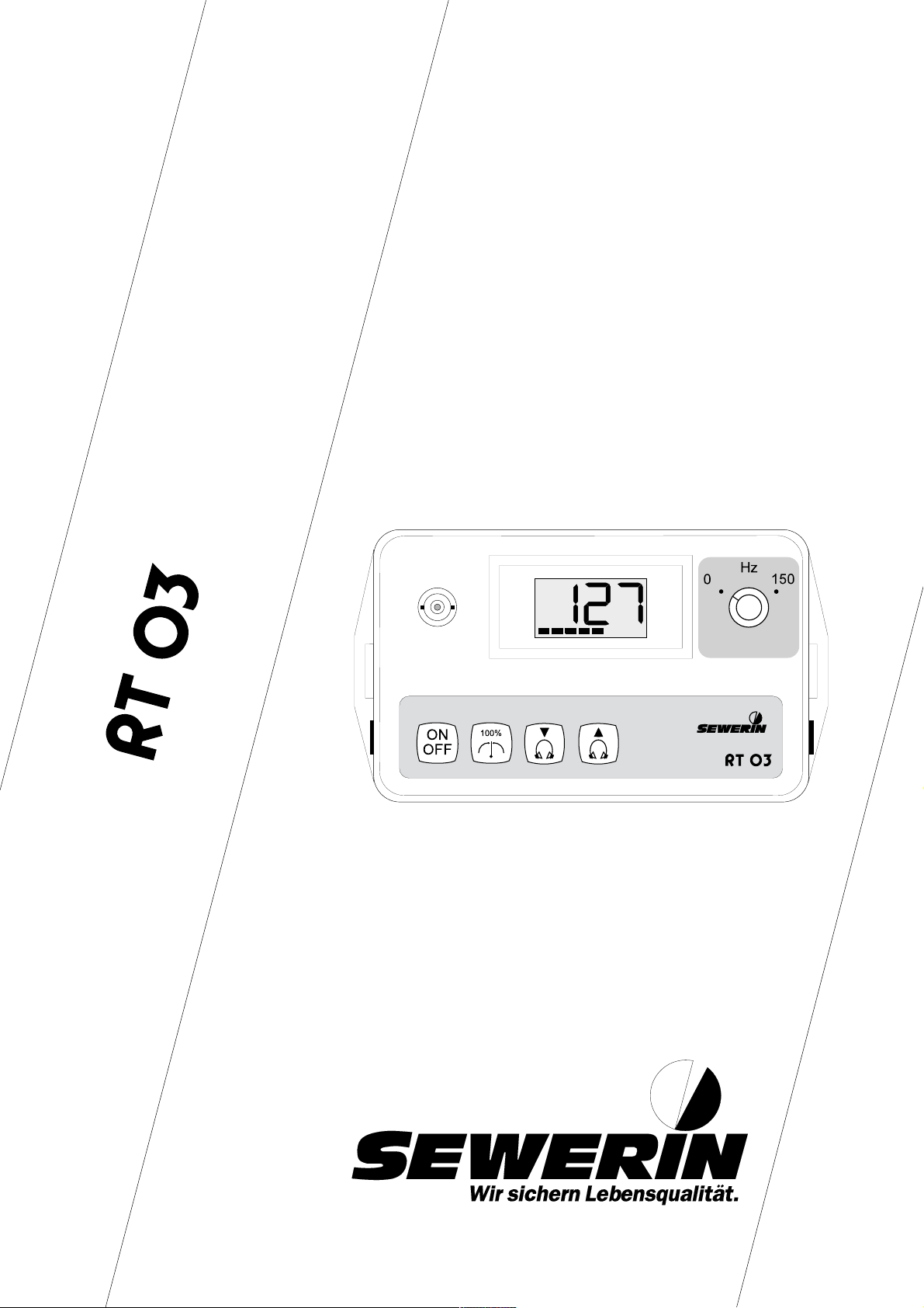
Design of the : RT 03
Display Field
Control Panel
Do not switch-on the device without antenna !
1
Page 4
THE EASY ACCESS
- Concise Operating Instructions -
Connect the microphone with the
appropriate adapter,
Connect the antenna,
Switch-on the transmitter,
A void noises for about 6 seconds.
READY !
2
Page 5

RT 03
Operating InstructionsOperating Instructions
Operating Instructions
Operating InstructionsOperating Instructions
102419 - 03/11.04.1997
......................
...........
......................
SeiteSeite
Seite
SeiteSeite
44
4
44
--
1818
-
18
--
1818
3
Page 6

For Y our Safety *
The law relating to technical instruments (Gerätesicherheitsgesetz) of
June 24th, 1968 (Federal law gazette I, page 717), and the amended
law of August 13th, 1979 (Federal law gazette I, page 1432) prescribe
the following instruction:
PAY ATTENTION TO THE OPERATING INSTRUCTIONS.
Each operation of this instrument presumes exact knowledge of and
adherence to these operating instructions.
The instrument is only for the described purposes.
LIABILITY FOR FUNCTION AND/OR DAMAGES
The liability for the proper function of the instrument is irrevocably
transferred to the owner or user in case that the instrument has been
serviced or repaired by personnel not employed or authorized by the
SEWERIN-Service Team, or if the instrument is operated in a manner
which does not correspond to its intended use.
For this reason, always use original SEWERIN accessories for your
RT 03.
The Hermann Sewerin GmbH does not accept liability for any damages resulting from non-observance of the above indications. The
warranty and liability conditions contained in our general terms of sale
and delivery are not extended by the above indications.
Subject to technical changes within the scope of further development.
HERMANN SEWERIN GMBH
*
Insofar as reference is made to laws, regulations and standards, these are based on the legal
order in the Federal Republic of Germany.
4
Page 7

CONTENTS PAGE
For Your Safety.......................................................................................4
1.0 The RT 03 .....................................................................................6
1.1 Use................................................................................................7
1.2 System components...................................................................... 7
2.0 The Control of the RT 03 ............................................................8
2.1 Switching on the device.................................................................8
2.2 Operating modes..........................................................................9
2.3 Adjustment of the headphone volume......................................... 10
2.4 Filter selection .............................................................................10
2.5 Function control...........................................................................11
3.0 Charging.....................................................................................12
4.0 Possible operating trouble.......................................................14
5.0 Technical hints ..........................................................................16
6.0 Technical specification ............................................................. 17
7.0 Accessories ...............................................................................18
5
Page 8

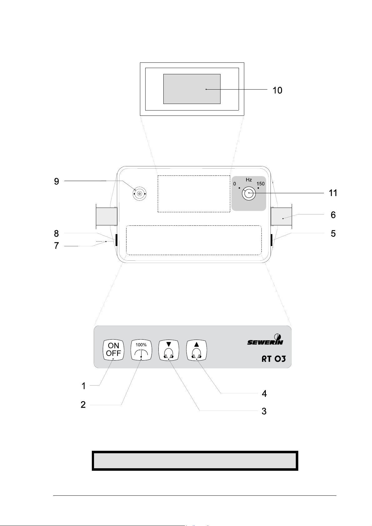
1.0 The RT 03
(Please refer to the picture on the inner front page !)
POS. DESIGNATION FUNCTION
CONTROL PANEL
1 ON/OFF button Switching on
2 Level button Set the optimal value for
3 "Turn down" button Turning down the headphones
4 "Turn up" button Turning up the headphones
Switching off
radio transmission
DEVICE
5 Microphone socket
6 Carrier-belt
7 Loading socket for car adapter or plug power
device
8 Headphone socket
9 Antenna socket
DISPLAY FIELD
10 LCD display Display of:
Level volumes
Instantaneous values
Error messages
Operating hours still available
11 Filter-switch Select 0 Hz or 150 Hz as
high-pass
= press switch
6
Page 9

1.1 Use
The radio transmitter RT 03 serves to receive the noise coming
from fittings and to transmit it by radio to the correlator which is also
delivered (! see the appropriate Operating Instructions).
1.2 System components
To make the transmitter ready for use, the following components
are necessary:
● antenna,
● headphones (delivered with the correlator),
● piezoelectric microphone,
● adapters (for attachment to hydrants
and sliding valves) or
● horseshoe magnet (for fastening on
metallic pipes without fittings).
7
Page 10

2.0 The Control of the RT 03
2.1 Switching on the device
The start up procedure of the RT 03 is the following:
" connect the piezoelectric microphone with the microphone
socket (pos. 5),
" screw the appropriate adapter (square adapter or
horseshoe magnet) to the microphone,
" attach the microphone to the fitting or the pipe,
" connect the antenna (pos. 9) and
" switch-on the device (pos. 1).
##
# Do not switch-on the device without antenna !
##
Immediately after the switching on of the device, the automatic
level adjustment is carried out for about 6 secounds. During this
time you should avoid to make noise
(taps, voices or the like). The number
of bar segments on the bar chart shows
the number of operating hours still
available.
The RT 03 now is transmitting and
permanently signals the relation
between the actual and the adjusted
level.
##
#
##
By means of the headphones (pos. 8), you can listen to the noise
coming from the fitting. Now , all adjustments of the transmitter
having been made, you can begin with the correlation.
8
Page 11

2.2 Operating modes
T o change the operating mode, the „Turn down“ button (pos. 3) and
the „Turn up“ button (pos. 4) are to be pressed at the same time.
Y ou can select between the three possible operating modes by
actuating the „Turn down“ (pos. 3) or the „T urn up“ button (pos. 4):
For a moment, the display will indicate that
now an adjustment operation is executed.
Automatic level adjustment
!normal adjustment when switching on the
transmitter and for correlation;
By actuating the level button (pos. 2), this
adjustment can be repeated at any time. This
is recommended when e.g. the environment
noises were too loud during the first automatic
level adjustment.
Manual level adjustment
! operating mode for the sonic speed
measurement;
During transmission the level button (pos.2)
is locked; now the level is adjusted by the
"Turn down" button (pos. 3) or the "Turn up"
button (pos. 4) and can be controlled with the
headphones.
Radio module switched off
!operating mode for the electro-acoustic
water leak detection;
For this you will need an appropriate ground
microphone or a test rod. This adjustment is
announced by the regular blinking of the LCD
display. With the level button (pos. 2) the
headphones can be switched on or off.
The desired adjustment is acknowledged by activating the level
button (pos. 2).
9
Page 12

2.3 Adjustment of the headphone volume
The desired headphone volume can be adjusted by means of the
„Turn down“ button (pos. 3) or the „Turn up“ button (pos. 4).
This is displayed by a „migrating gap“
within the segment range of 8 bars.
In this connection:
Gap on the left means - headphone volume at „0“,
Gap at right means - volume at maximum.
After switching off the transmitter the finally adjusted headphone
volume will be preserved.
2.4 The Filter selection
With the rotating switch the following is beeing chosen:
"ØHz" high pass, every noise portion is being amplified and
transmitted.
"160 Hz" high pass, only noise portions above 160 Hz are
being transmitted.
The optimum setting depends on a particular situation and has to
be tried out. With the position "160 Hz" interfering noises within the
deep frequencey range can (i.e.) be surpressed effectively. The
position 0 Hz should be tried out amplified when using the
hydrophone.
Basically the same filter position should be used for the radio
transmitter 1 and 2.
10
Page 13

2.5 Function control
It is recommended to control the functioning of the transmitter by
regular intervals. For this, switch-off the device and activate
simultaneously the ON/OFF button (pos. 1) and the level button
(pos. 2).
Afterwards the automatic level adjustment is carried out and the
device is transmitting.
Follows a bar segment check by the
LCD display, and
the display of the number of the
software version.
11
Page 14

3.0 Charging
During operating mode, the loading position of the RT 03 is
constantly being displayed by segments.
If the RT 03 has not been charged for a substantial time, the
remaining operation period decreases by way of self-discharging.
Under these circumstances, the remaining operation time indicated
can be higher than the time actually still available.
The number of segments displayed
indicate the remaining hours of
operation.
If the battery symbol is displayed during
normal operation time, the accuvoltage has fallen so much that the
remaining operation time stands
aprox. by 15 min.
In case the accu-voltage is falling further , the RT 03 automatically
switches off.
The transmitter can either be recharged by the plug power device,
delivered with the RT 03 (230V≈/12V=) or by the car connection
adapter (12V=/12V= or 24V/=12V=) respectively. Hereby the
transmitter - in switched-off position - is connected via its charging
socket with the chosen loading adapter. After a short acustic signal
the following message is displayed:
e.g. 16 Hrs. charging time are still
required before the battery is
recharged fully.
(In this instance the remaining
operating time is 2 Hrs).
After that time the transmitter is fully charged and changes
automatically into the buffer operation, thus covering the self
discharging loss. The transmitter is ready for continued use, the
accu is not sustaining any damage.
12
Page 15

Once the RT 03 has been recharged,
the charging time is no longer
displayed. The available operating
time will be at least 10 Hrs.
In case the accu has been almoast completely discharged thus
making a further operation impossible, it can also be worked via
external 12V= instead of recharging: connect the transmitter to
a 12V and actuate the on/off key.
While charging heat is developing within the instrument.
##
#
##
##
#
##
When charging in increased outside temperatures (i.e.
during summer or inside the vehicle) please open the case.
There will be a 16 hour charging cycle with each new power
supply . T o obtain the max. accu level, a new charging cycle
should only be startet once the accu has been discharged.
13
Page 16

4.0 Possible operating trouble
LCD-Display Description of fault
Warning tone : no
Source : headphone
volume to full
Remedy : device switches
itself over to a lower
value
Warning tone : yes
Source : multiply overflow
Remedy : SEWERIN-Service
Warning tone : yes
Source : error when activating
the last headphone
adjustment
Remedy : SEWERIN-Service
Warning tone : yes
Source : ROM error
Remedy : SEWERIN-Service
Warning tone : yes
Source : RAM error
Remedy : SEWERIN-Service
Warning tone : yes
Source : EEPROM error
Remedy : SEWERIN-Service
14
Page 17

LCD-Display Description of fault
Warning tone : yes
Source : radio module
voltage differs from
the nominal value
Remedy : SEWERIN-Service
ROM = read-only memory
RAM = random access memory
EEPROM = electrical erasable programmable read-only memory
15
Page 18

5.0 T echnical hints
The radio transmitter RT 03 corresponds to the legal prescriptions
relating to radio technical installations. Its transmitting power is sufficient for the transmission of signals over a distance of about 1,000
m. In that case the transmitting and the receiving antenna are in
direct visual contact.
The range is reduced if the transmitter or the receiver are in metalcased places (e.g. in a car or a metal-armored cellar).
Nevertheless a reliable measuring situation can be established, if
necessary , by means of the extension of the microphone cable.
T o ensure a better handling, the radio transmitter can be operated
from a case which is delivered with the device. The connections for
aerial, microphone and loading adapter are outside of it.
Should water or humidity have penetrated into it, the device is to be
stored with opened case.
16
Page 19

6.0 Technical specification
Serial number : 009 02 . . . .
Characteristics : automatic adjustment of the level of
Connections : sockets (6.3 mm) for microphone
Type Design Number
leakage noises,
display of the leakage noise level as
percent-age,
micro-processor controlled loading
technics,
under voltage switching off
and headphones,
charging socket,
BNC socket for antenna
Power supply : incorporated accumulator (12 V, 4 Ah),
operating hours: approx. 10,
charging cycle 16 h,
chargingcurrent 700 mA
Acoustic signals
- Errors : continuous tone
- Low voltage : interval signal
Transmitting power : 500 mW
Range : approx. 1,000 m
Band width : 8 Hz ... 4 kHz
Dimensions (WxHxD): 175 x 145 x 105 mm
Weight : approx. 2.6 kg
Range of temperature
- Device operating: -10° up to +40°C
- Device stored : -10° up to +70°C
Protection : according to IP 54
17
Page 20

7.0 Accessories
CARRIER-BELT Leather , adjustable from 0.5 to 1.0 m,
CHARGING UNIT
- Plug power device Power supply by mains-connection,
- Car connection adapter Power supply by the car battery,
PIEZOELECTRIC with an extremely high noise
MICROPHONE sensitivity and in a moisture-sealed
HYDROPHONES sound recorder particularly
for carrying the device
230 V≈ / 12 V=
12 V= / 12 V= or 24 V= / 12 V=
and rust-proof design
recommended to be placed into the
water column,
also recommended for the leak
location in non metallic pipes
GAS AND AIR SOUND to locate leakages on pipes which
MICROPHONE contain a gaseous medium
CABLE EXTENSION to extend the microphone cable to a
length of 5/10 m
ADAPTERS for hydrants, slide and stop valves in
houses and for a fixed attachment of
piezoelectric microphones
HORSESHOE MAGNET to attach the piezoelectric microphone
to fittings or pipes
HEADPHONES stereo design, for the controlling of
leak noise
18
Page 21

Hermann Sewerin GmbH
Robert-Bosch-Straße 3 · D-33334 Gütersloh
Telefon 0 52 41/9 34-0 · Telefax 0 52 41/9 34-4 44
http://www.sewerin.de
 Loading...