

Page 1
RMLD-IS
Operating
Instructions
Page 2

Measurable success by Sewerin equipment
Congratulations. You have chosen a quality instrument manufactured
by Hermann Sewerin GmbH.
Our equipment will provide you with the highest standards of perfor-
mance, safety and efciency. They correspond with the national and
international guidelines.
Please read and understand the following operating instructions before
using the equipment; they will help you to use the instrument quickly and
competently. If you have any queries we are available to offer advice
and assistance at any time.
Yours
Hermann Sewerin GmbH
Robert-Bosch-Straße 3
33334 Gütersloh, Germany
Tel.: +49 5241 934-0
Fax: +49 5241 934-444
www.sewerin.com
info@sewerin.com
SEWERIN SARL
17, rue Ampère - BP 211
67727 Hoerdt Cedex, France
Tél. : +33 3 88 68 15 15
Fax : +33 3 88 68 11 77
www.sewerin.fr
sewerin@sewerin.fr
SEWERIN IBERIA S.L.
Centro de Negocios Eisenhower
Avenida Sur del Aeropuerto
de Barajas 24, Ed. 5 Of. 2C
28042 Madrid, España
Tel.: +34 91 74807-57
Fax: +34 91 74807-58
www.sewerin.es
info@sewerin.es
Sewerin Ltd
Hertfordshire
UK
Phone: +44 1462-634363
www.sewerin.co.uk
info@sewerin.co.uk
Sewerin Sp.z o.o.
ul. Twórcza 79L/1
03-289 Warszawa, Polska
Tel.: +48 22 675 09 69
Faks: +48 22 486 93 44
Tel. kom. +48 501 879 444
www.sewerin.pl
info@sewerin.pl
Page 3

Operating Instructions
RMLD-IS
Remote Methane Leak Detector
01.10.2015 – 107216 – en
Page 4

Contents Page
Overview ..................................................................................1
Warranty ...................................................................................4
Warning notices ......................................................................5
Section I (System description) ............................................... 6
1.1 Technical data for the RMLD-IS system .................................... 6
1.2 RMLD-IS system components ..................................................8
1.2.1 Controller ................................................................................8
1.2.2 Transceiver.............................................................................8
1.2.3 Carrying strap .........................................................................9
1.2.4 AC/DC adapter ....................................................................... 9
1.2.5 Carrying case ......................................................................... 9
1.2.6 Headphones ........................................................................... 9
1.3 Accessories ............................................................................. 10
1.3.1 Dual shoulder strap harness ................................................10
Section II (Battery charging) ................................................ 11
2.1 Rechargeable battery .............................................................. 11
2.2 AC/DC adapter ........................................................................ 13
2.3 Charging procedure ................................................................13
Section III (Operating the RMLD-IS) ....................................14
3.1 Switching on the RMLD-IS ......................................................16
3.2 Switching on the spotter laser .................................................17
3.3 Switching off the RMLD-IS ......................................................18
3.4 Using the menus .....................................................................18
3.5 Using DMD mode .................................................................... 20
3.6 Using the Pure Tone mode ......................................................21
3.7 Self-test and calibration ........................................................... 22
3.7.1 Calibration override .............................................................. 25
I
Page 5

Contents Page
Section IV (Monitoring with the RMLD-IS) ..........................27
4.1 Monitoring with the RMLD-IS ..................................................27
4.2 Long range scanning ............................................................... 30
4.3 Dealing with false detections ................................................... 31
4.4 How does the RMLD-IS measure gas concentrations? ..........32
Section V (Maintenance and troubleshooting) ................... 36
5.1 Troubleshooting the device .....................................................36
5.2 Maintenance ............................................................................ 40
Appendix ................................................................................41
Glossary ..................................................................................41
Daily log of RMLD-IS self-test and calibration ......................... 43
II
Page 6
Overview
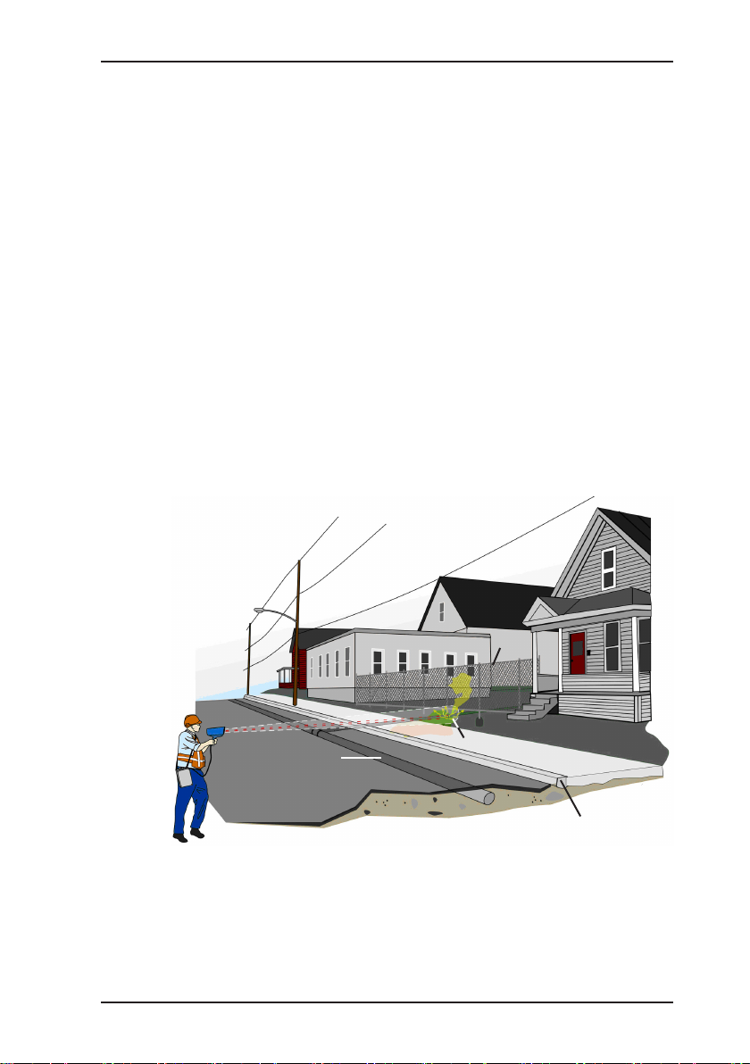
The Methane Leak Detector (RMLD-IS™) uses state-of-the-art
technology to identify methane leaks from a considerable dis-
tance. The RMLD-IS the rst of a new generation of leak monitoring devices that signicantly improve the productivity and safety
of mobile monitoring activities.
Using the RMLD-IS, it is now possible to monitor areas that are
hard to reach or are not easy to access. The use of TDLAS (Tunable Diode Laser Absorption Spectroscopy) laser technology
means that the RMLD-IS does not need to be located directly
in the gas plume. As the laser passes through a gas plume, the
methane absorbs a portion of the light, which is then detected by
the RMLD-IS. This technology makes it possible to detect leaks
along the line of sight without always having to walk the full length
of the gas pipe.
Fence
Gas pipe
Road (asphalt)
Figure 1-2
Leak
Kerb
Remote detection using laser technology, allows areas to be safely
monitored that may otherwise be difcult to reach, such as busy
roads, properties with guard dogs, fenced off areas, and other
hard to access places.
1
Page 7
The device is designed to selectively detect methane only, and
will not give a false alarm should other hydrocarbon gases be
present. Gas concentration is calculated according to the amount
of infrared light absorbed by the gas. Because the gas is detected
along the line of sight of the laser, the concentration is given in
ppm•m (parts-per-million•meter). In other words, the RMLD-IS
measures the concentration of the gas cloud multiplied by its
width. Depending on the local meteorological conditions, a given
amount of gas escaping from the ground will produce a plume
that varies in size and uniformity of concentration levels. Gas
plumes are variable in nature and depend on the soil conditions,
temperature, wind, and leak rate.
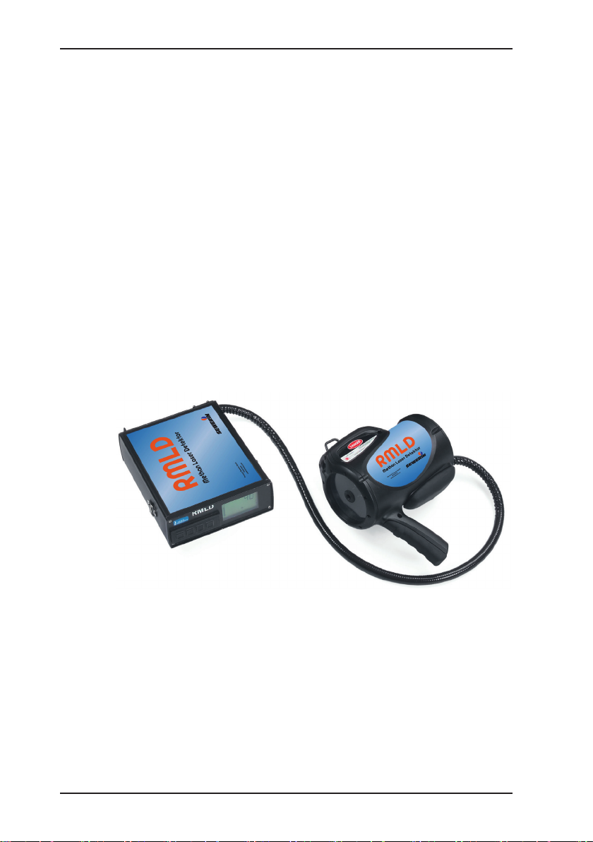
The RMLD-IS consists of two main components that interact with
each other:
z Transceiver
z Controller
Figure 1-3: The RMLD-IS system consists of a laser transmitter/receiver
and a controller
2
Page 8

The transceiver has two lasers. The infrared laser is invisible
and is continuously active when the device is switched on. The
visible green spotter laser must be activated by the operator by
pressing the trigger button.
The RMLD-IS can be operated in a wide variety of environmental
conditions, including cold and hot weather and light rain. Its rugged design will withstand normal eld use and operating conditions. Sensitivity and range are not negatively affected by normal
amounts of dust on the optics window.
The RMLD-IS includes integrated self-test and calibration functions that guarantee correct functioning of the device. The calibra-
tion cell built into the carrying case allows the operator to carry
out the self-test and calibration as part of a daily start up routine.
While in use, the RMLD-IS continuously monitors several parameters to ensure that the instrument is functioning correctly. Should
any of these parameters exceed the specied operating limits,
an audible alarm will sound and a fault/warning error message
will be shown on the display.
The device is supplied with a training video. It is strongly recommend that all operators view the video in order to learn the basic
techniques required to carry out monitoring using the RMLD-IS.
3
Page 9

Warranty
To ensure reliable operation and safety, it is essential to pay attention to
the following notes.
Hermann Sewerin GmbH is not liable for damage caused by failure to
comply with these notes. The guarantee and liability conditions of the sales
and delivery conditions of Hermann Sewerin GmbH are not extended by
the following notes.
z This product may only be taken operated after reading thoroughly the
accompanying operating instructions.
z This product may only be used for intended applications.
z This product is destined for industrial and commercial applications.
z Repairs may only be performed by the manufacturer or appropriately
trained staff.
z The manufacturer is not liable for damage resulting from arbitrary modi-
cations of the product.
z Only spare parts may be used which are approved by Hermann Sewerin
GmbH.
Technical changes within the scope of further development reserved.
4
Page 10

Warning notices
z The visible green Spotter laser is a Class IIIa laser product. Do not look
into the beam or view directly using optical instruments.
z Do not attempt to repair this device. Please refer to Section V in this man-
ual if the device does not work correctly or indicates a fault or warning.
z Do not switch on or use the RMLD-IS indoors if there is any indication,
possibility or suspicion that an explosive level of gas may be present.
z Do not charge in a danger zone.
z Replacing components can have an effect on the intrinsic safety of the
device.
z To avoid sparks in dangerous environments, rechargeable batteries must
only be exchanged in areas known to be safe.
5
Page 11

Section I (System description)
1.1 Technical data for the RMLD-IS system
Detection method: TDLAS (Tunable Diode Laser
Absorption Spectroscopy)
Measurement range: 0 to 99.999 ppm•m
Sensitivity: 5 ppm•m at a distance of 0 to 15 m
Min. 10 ppm•m at a distance of 15 to
30 m
Detection range: 30 m (nominal). Actual distances
may vary depending on the type of
background and other conditions.
Beam size: Conical beam, width 56 cm at 30 m
Alarm modes for
detection:
System fault
warning:
Self-test and
calibration:
Standards complied
with:
DMD (Digital Methane Detection)
z Audible signal, variable pitch accord-
ing to concentration when the alarm
activation threshold is exceeded.
z Alarm activation threshold adjustable
from 0 to 255 ppm•m.
Pure Tone
z Continuous audible signal, variable
pitch according to concentration.
Audible signal and symbol on display
Integrated self-test and calibration
function for checking correct operation
and adjusting laser wavelength for best
sensitivity. Gas test cell integrated into
carrying case
EMC (EN 61000-6-2, EN 6100-6-4)
(pending)
6
Page 12

Laser safety (eye
protection):
CDRH, ANSI and IEC
z IR detection laser
– Class I
z Green spotter laser
– Class IIIa: Do not look into the beam
or view directly using optical instruments.
Display: Large, easy to read display with
backlight (0.75", numeric)
Operating
-17 °C to 50 °C
temperature:
Humidity: 5 to 95% (non-condensing)
Housing: IP54 (protected against water spray
and dust)
Weight of device: 4 kg (transceiver 1.3 kg, controller 2.7 kg)
Carrying case: 6.4 kg; 86 cm x 24 cm x 36 cm
Power supply: Internal lithium-ion rechargeable
battery
Battery operating
life:
8 hours at 0 °C with backlight switched
off (internal battery)
AC/DC adapter: External adapter, 100 – 240 V~, 1.6 A,
50 – 60 Hz with charge indicator
(max. 8 hours for full charge)
Shoulder strap: Single shoulder strap with pad
Ergonomic dual shoulder strap harness
with belt (optional)
Intrinsic safety: Class 1 Division 1 Group D, T4
UL 913 MetLab listing #E112840
7
Page 13
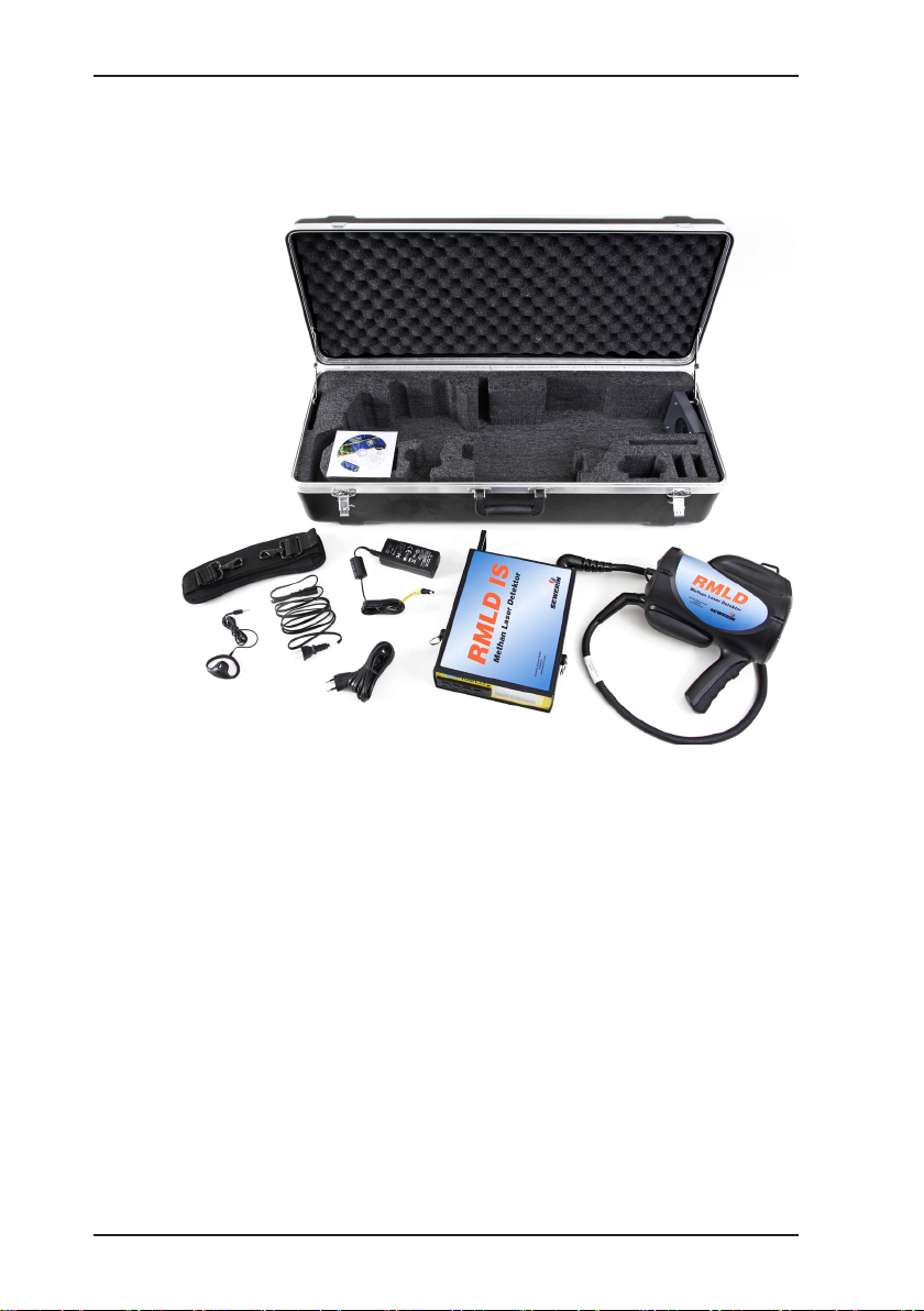
1.2 RMLD-IS system components
This section describes the features of the RMLD-IS. Please refer
to Figure 1-4 for illustrations of individual parts.
Figure 1-4: System components
1.2.1 Controller
The controller provides the user interface, menu selection keys,
and external connections including: RS-232 port, AC/DC adapter
port, external power supply port, headphone port, and power
switch.
1.2.2 Transceiver
The transceiver houses the infrared detection laser and the visible green spotter laser, and has a trigger for the spotter laser.
The unit also has hooks for the carrying strap.
8
Page 14

1.2.3 Carrying strap
The RMLD-IS comes complete with a single carrying strap, including shoulder pad. An optional dual shoulder strap harness
is also available.
1.2.4 AC/DC adapter
An AC/DC adapter is supplied with the device for recharging the
battery.
The AC/DC adapter is a universal adaptor operating at
110 – 240 V~, 1.6 A and 50 – 60 Hz.
2 LEDs on the front of the controller display the current battery
charge level.
1.2.5 Carrying case
The carrying case provides protection for the device during
transportation and storage. The device must always be stored
in this case when not in use. A gas calibration cell is integrated
into the case.
1.2.6 Headphones
Allow audible signals to be heard through headphones instead
of the external loudspeaker.
9
Page 15

1.3 Accessories
1.3.1 Dual shoulder strap harness
The dual shoulder strap harness provides additional comfort and
support when carrying the device for extended periods. The inte-
grated lanyard is used to carry the weight of the transceiver and
provides additional stability and control over the unit during moni-
toring activities. SEWERIN recommends the use of this harness
by all personnel who operate this equipment for extended periods
of time in order to limit fatigue when holding the transceiver and
to improve monitoring technique.
10
Page 16

Section II (Battery charging)
2.1 Rechargeable battery
The RMLD-IS is tted with an internal lithium-ion battery that
provides the main source of power for the device. This battery
is designed to provide 8 hours of device operation when fully
charged. The battery must be recharged every time the device is
not in use in order to guarantee uninterrupted use of the device.
A battery charge indicator is provided on the display. This indicator is accurate to within 20% of actual capacity. The indicator
should only be used as a guideline value. Always start the day
with a fully charged battery to ensure that the device can be used
for the whole day.
Battery charge indicator
Figure 2-1
Note
To ensure the battery stores its full capacity,
charge when the ambient temperature is between
10 °C – 30 °C.
The device should have a battery level of at least
40 % (3 – 4 bars) if it is to be stored for a period of
longer than a week. Store at approx. 20 °C room
temperature and 70 % relative humidity.
11
Page 17

CAUTION!
Prolonged periods of not using the rechargeable
battery either inside or outside the device may result
in irreparable damage.
It is advisable to check once a month that the bat-
tery level remains at at least 40% during storage.
Never fully discharge the rechargeable battery or
leave it stored for prolonged periods of time as this
will reduce the useful life and capacity of the battery.
CAUTION!
To prevent damage to the battery or electrical circuits, always plug the AC/DC adapter into a surge-
protected socket.
12
Page 18

2.2 AC/DC adapter
The RMLD-IS is supplied with a universal AC adapter. The adapter
plug can be changed according to the sockets which are available.
2.3 Charging procedure
DANGER! Risk of explosion due to sparks
High charging current occurs when batteries are
being charged.
Only charge the device outside of explosive areas.
Carry out the following procedure to recharge the internal battery.
1. Switch off the device.
2. Insert the AC plug into a surge-protected socket.
3. Plug the AC/DC adapter into the external power supply.
4. A red LED will ash on the front of the control unit to indicate
that the charging process is underway.
5. Allow the device to charge until the green LED indicator is
continuously lit or off.
6. Unplug the adapter.
Warning!
Only charge the battery using the dedicated RMLD-IS
adapter supplied by SEWERIN. Use of any other type
of adapter may cause severe damage to both the battery and electrical circuits.
13
Page 19

Section III (Operating the RMLD-IS)
The section provides information on operating the RMLD-IS. This
includes an explanation of how to use the menu, how to set operational parameters, and the procedures for activating various
features of the device.
5 6 7 8
1 2 3 4 13 14 15
Figure 3-1 RMLD-IS front panel with display.
(Note: the illustration shows all icons displayed
simultaneously. During actual operation, only those symbols
related to an active function will be displayed.)
1 DMD key Press this key to activate/deactivate
DMD mode
2 Up key Press this key to increase a value or to
acknowledge an on-screen prompt.
9
10
11
12
14
3 Down key Press this key to decrease a value.
4 SELECT key Press this key to scroll through the
menu options.
Display
5 Battery charge
Shows remaining charge in the battery.
indicator
6 DMD symbol This symbol indicates when DMD
detection mode is active.
7 Gas concentration Shows the amount of gas detected in
ppm•m. The display “1-------” indicates
a value is out of range.
Page 20

8 Volume Shows the volume level for the loud
speaker and headphones.
9 WARNING symbol This symbol indicates that the device
is operating outside functional limits.
10 ERROR symbol This symbol indicates a fault, i.e. the
device is not functioning correctly.
11 Backlight symbol This symbol indicates that the
backlight is switched on.
12 Spotter symbol This symbol indicates that the spotter
laser is active.
13 RE-TRY This symbol indicates that the self-test
has not completed successfully and
needs to be carried out again.
14 SELF-TEST This symbol indicates that self-test
mode is active.
15 OK This symbol indicates that the self test
completed successfully.
15
Page 21

Figure 3-2: RMLD-IS rear panel
HEADPHONE port Socket for the headphone jack.
POWER SWitch Pressing this switch turns the device
on/off.
External power
Socket for the external adapter.
supply connector,
EXT. POWER
RS-232 port Female sub-D connector for PC
interface (only used for factory
calibration).
3.1 Switching on the RMLD-IS
Press the power switch located on the rear panel. When the device is switched on, the green spotter laser will ash briey and
the display will show all symbols together for a short period. The
display will then switch to the main operating mode showing the
ppm•m measurement value. The warning symbol will also be
displayed briey during the warm up period for the laser. This
warning should disappear after a few seconds. The device will
start up using the same settings that were active when it was
switched off (e.g. alarm activation threshold, spotter active, etc.).
16
Page 22

Note:
The infrared detection laser is always active and the
device continuously monitors methane concentration whenever it is switched on.
3.2 Switching on the spotter laser
CAUTION!
The green spotter laser is controlled by the operator
and is only switched on when the spotter trigger is
pressed. When using the green spotter laser, never
point the beam at another person’s eyes and take
care not to distract drivers of vehicles. This laser is of
the same type used in commercially available laser
pointers, as commonly used for presentations. This
laser is safe provided it is used correctly.
Danger!
The visible green spotter laser is a Class IIIa laser
product. Do not look into the beam or view directly
using optical instruments.
Spotter laser
IR detection laser
Spotter trigger
Figure 3-3
17
Page 23

3.3 Switching off the RMLD-IS
Press the power switch located on the rear panel. The device
will switch off. All settings will be saved automatically (e.g. alarm
activation threshold, spotter active, etc.).
3.4 Using the menus
The RMLD-IS allows the operator to set certain operational parameters and to activate/deactivate functions. The following operational parameters can be changed by the operator:
1. Volume
2. Alarm activation threshold
The following functions can be activated and deactivated:
1. Self-test
2. Spotter
3. Backlight
Pressing the menu key will scroll through the menu options in the
following sequence:
Self-test
z Press the up key to start the self-test and calibration.
– Press the up key to acknowledge on-screen prompts (OK
or RE-TRY)
18
Ready to start self-test
VOL
z Press the up key to increase the volume
z Press the down key to decrease the volume
Page 24

SPO
z Press the up key to activate or deactivate the spotter laser
AL
z Press the up key to increase the alarm activation threshold
z Press the down key to decrease the alarm activation threshold
Figure 3-4
BACLI
z Press the up key to activate or deactivate the backlight for the
display
Figure 3-5
The ppm•m measurement value will not be updated while menu
options other than the main screen are displayed, however the
device will continue to function normally.
19
Page 25

3.5 Using DMD mode
DMD (Digital Methane Detection) mode is a highly sophisticated
detection algorithm that greatly enhances the use of the RMLD-IS.
In most situations, the operator should carry out monitoring with
DMD mode activated. Press the DMD key to activate DMD mode
(the DMD symbol will be shown on the display). This mode can
only be activated when the display is showing the main monitoring screen.
Figure 3-6: The DMD symbol is displayed while DMD mode is active.
When DMD mode is active, no sound is produced until methane
is detected. The pitch of the sound is dependent on the concentration of methane. The higher the pitch, the higher the methane
concentration.
A low-pitched pulsating or continuous sound indicates a warning
of low infrared laser intensity or a problem with the device. A warn-
ing symbol is also displayed in cases where the light intensity is
too low (see Section 4.2). The operator must move closer to the
gas plume in order to be in detection range.
If the warning continues to be displayed, then this may indicate
that there is a fault in the device. Check the error code and follow
the instruction in Section V.
When in DMD mode, the device will indicate that methane has
been detected when the ppm•m measurement value exceeds the
average background level plus the alarm activation threshold, or
when the reading is excessively high. Even when the low light
intensity warning signal is audible, the RMLD-IS may still be able
to detect very high gas concentrations; this situation is indicated
by a higher pitched sound.
The alarm activation threshold controls the sensitivity in DMD
mode. The alarm activation threshold value can be adjusted by
the operator. The monitoring procedures used by some organisations may require that a specic value is used or a that a certain
adjustment procedure is followed. Set the alarm threshold value
to a level that gives a low number of false alarms, while at the
same time not being so high that gas leaks are not detected.
DMD symbol is displayed
20
Page 26

To change the alarm activation threshold, scroll through the menu
options until the “AL” option is displayed. Press the up/down key
to increase/decrease the threshold. Setting a higher threshold
value will decrease the sensitivity of the device.
3.6 Using the Pure Tone mode
In “Pure Tone” mode, the RMLD-IS will produce a continuous
tone that is related to the instantaneous concentration level. The
higher the pitch of the tone, the higher the methane concentration. If no sound is heard then this indicates low light intensity
or a fault in the device. Note that the pitch will increase with in-
creasing distance scanned. This is due to the background level
of methane in the air.
Figure 3-7
“Pure Tone” mode is most effective when used over short dis-
tances and can be helpful in detecting low concentrations or in
identifying the location of the highest gas concentration.
Pitch is proportional to
ppm•m measurement value
DMD symbol is not displayed
21
Page 27

Follow the procedure below to identify a leak producing a low
concentration of gas:
1. Stand about 3 m from the leak, ideally upwind.
2. Sweep the laser back and forth across the leak, maintaining
a constant distance.
3. Listen for a persistent increase in pitch as the beam passes
through the leak. The pitch will only increase slightly if the
leak is very small.
Follow the procedure below to identify the location of the highest
concentration of gas:
1. Stand about 3 m from the leak, ideally upwind.
2. Sweep the laser in and around the area of the leak, starting
from the upwind side.
3. Listen for the highest pitched tone.
4. Change the angle of the sweep slightly and rescan the area
around the leak.
5. If the location that produces the highest pitched tone is consistent, then this indicates the location of the leak.
6. Continue scanning if the pitch of the tone produced is not the
same. It is possible that the gas plume may be drifting around,
which will produce inconsistent readings. In some cases, the
gas plume may be so large that precise pinpointing of the
source is not possible.
3.7 Self-test and calibration
The RMLD-IS features an integrated function for carrying out a
self-test and calibrating the laser wavelength. The self-test func-
tion should be run on a daily basis to ensure trouble-free operation of the device. Each self-test and each calibration should be
recorded in a daily log. An example of a daily log can be found
at the end of this manual.
22
Page 28

Proceed as described below to carry out the self-test and calibration.
1. Remove the controller from the carrying case.
2. Switch on the device and allow it to warm up for 2 to 3 minutes.
3. Place the transceiver in the carrying case in the position de-
signed for this purpose, ensuring that it is level and properly
seated. The space between the transceiver, receiver and
calibration cell must be free of obstacles.
4. Press the SELECT key until the SELF-TEST symbol appears
on the display (note: the RE-TRY and OK symbols will also
be displayed).
Figure 3-7
5. Press the up key to start the test. The number 255 will be
displayed.
6. The OK symbol will be displayed if the device completes the
self-test satisfactorily.
– If the RE-TRY symbol is displayed, then the self-test was
not completed successfully. Press the up key to restart the
self-test, referring to the instructions in the following section,
“Calibration override”.
7. Press the up key. This will initiate the procedure for calibrating
the laser wavelength. The procedure takes about 45 seconds
to complete, during which time the measured gas concentration value can be seen to vary up and down.
8. The OK symbol will be displayed when the device has suc-
cessfully completed calibration of the laser.
– The RE-TRY symbol will be displayed if the device is un-
able to successfully calibrate the laser. Press the up key to
restart the self-test.
9. Press the up key to acknowledge.
10. Press the SELECT key to scroll back through the display
modes until the main screen is seen.
23
Page 29

What if the device failed to successfully complete the selftest or calibration?
This is usually caused either by the transceiver being positioned
incorrectly in the carrying case or by a drift in the laser wavelength.
Ensure that the device is in the correct position, level and prop-
erly seated. Observe the gas concentration. This is usually around
1,100 ppm•m, however values between 500 and 2,000 ppm•m
are acceptable. Restart the self-test and calibration after the above
points have been checked.
24
Page 30

3.7.1 Calibration override
Proceed as described below if the device calibration fails at Step
6 due to low initial measurement values.
1. Ensure that the device is still in the self-test menu (see Step
6 above).
2. Override the normal self-test function by pressing the DMD key.
This will cause the laser calibration procedure to be carried out.
3. “OK” will be displayed at the end of the rst sweep. Press the
up key again to restart the sweep.
4. “Self-Test OK” will be displayed at the end of this sweep.
Press the up key followed by the SELECT key to leave the
self-test menu.
– “RE-TRY” will be displayed if the procedure fails. This means
that the device will not function correctly. Please contact
SEWERIN directly for assistance.
Note:
Laser wavelength drift is a normal characteristic of
the RMLD-IS. Normally, the magnitude of the drift is
small and does not have any negative effect on the
self-test, provided this is carried out regularly. Monitoring work that is carried out using an uncalibrated
device may have to be repeated. Please contact
SEWERIN service if the initial measured concentration values are regularly so low that the calibration
override feature must be used repeatedly.
25
Page 31

The following table may help identify the cause of the problem if
the self-test fails:
Cause Corrective action
Low signal strength
or noise
Initial ppm•m
measurement value
too low or too high
Laser adjustment
failed
CAUTION!
If the device does not successfully complete a selftest after several attempts, do not use the device
for monitoring work before the problem has been
rectied. Please contact SEWERIN directly for assistance.
z Make sure that the battery is fully
charged.
z Ensure that the device is in the correct
position, level and properly seated.
z Make sure that the battery is fully
charged.
z Ensure that the device is in the correct
position, level and properly seated.
z Check the calibration cell for signs of
damage.
z Use the calibration override function.
z Make sure that the battery is fully
charged.
z Ensure that the device is in the correct
position, level and properly seated.
z Check the calibration cell for signs of
damage.
26
Page 32

Section IV (Monitoring with the RMLD-IS)
4.1 Monitoring with the RMLD-IS
The RMLD-IS is supplied with a training video, which is the best
way to get an overview of the techniques used. It is important to
learn these techniques in order to be able to effectively detect
and monitor methane gas leaks. The purpose of the video is to
familiarise personnel responsible for monitoring gas leaks with
how to use the RMLD-IS. The video does not provide any training
in basic leak monitoring techniques.Please refer to your organisa-
tion’s own training and procedural requirements for the specic
qualications necessary for leak monitoring.
Three conditions must be met before the RMLD-IS is able to
detect a gas leak:
1. The size and concentration of the gas plume must be greater
than the minimum permitted by the sensitivity of the device.
2. The infrared beam must pass through the gas plume.
3. The target background (i.e. ground, building, etc.) must reect
the infrared beam.
The concentration and size of the gas plume are inuenced by
various factors. Leaks where a low volume of gas is escaping will
only produce small or undetectable gas plumes. Additionally, some
types of surface (e.g. concrete) spread the gas through cracks
and holes in the surface, thereby creating leaks at several points.
Weather conditions such as strong wind and high temperatures
result in the gas plume being dispersed more quickly.The opera-
tor must take these factors and their corresponding effects into
account whilst carrying out monitoring.
The most important factors when using the RMLD-IS are correctly aiming and controlling the infrared beam.
The rst things to learn in order to effectively use the RMLD-IS
for monitoring are to gain control over the direction of the laser
and to use the correct speed of sweep. Sudden or jerky motions
may lead to false detections due to rapid changes in distance or
changes in the background reecting the laser. This type of
rapid motion can result in the area not being thoroughly scanned
by the laser.
27
Page 33

Below are some tips for patrolling the gas pipe on foot:
z Use a smooth sweeping motion.
z Maintain a target distance for the beam of 5 m to 7 m. This
means that the footprint of the beam on the ground is large
enough to provide good coverage, while still giving good control
over the path of the beam.
z Scan the areas around connections and valves as you ap-
proach them.
z Direct the beam at likely leak locations (e.g. cracks, poor veg-
etation, etc.).
Consider the following points when scanning a gas pipe or gas
meter in familiar locations:
z Make full use of the advantages of the beam by sweeping more
widely around the pipe.
z Trace out an “S” pattern with the beam while moving along
the pipe.
z Scan the area around the gas meter.
z Rescan the pipe in the opposite direction, again following an
“S” pattern.
z Move closer to the pipe if the area to be scanned is too far
away or raised ground means that the beam does not hit the
surface (dark zones).
28
Proceed as follows when scanning a gas pipe at an unfamiliar
location:
z Use an “X” pattern or similar to ensure that the area is thor-
oughly scanned.
z Target areas where gas typically escapes e.g. along streets
and pavements.
z Target areas where valves might be located.
z Scan along the foundations of buildings.
z Move closer to the pipe if the area to be scanned is too far
away or raised ground means that the beam does not hit the
surface, thereby causing dark zones (shadows).
Page 34

Proceed as follows when scanning a gas meter:
z Maintain a distance of at least 3 m from the gas meter to ensure
that the beam width is not too narrow.
z Thoroughly scan the ground in the area around the meter.
z Aim the device at the gas meter from the angle that provides
the best background behind the meter.
z If the meter is in the open, or a limited choice of angles means
there is no background available directly behind the meter,
scan the meter using a horizontal “Z” pattern, making sure to
maintain a constant sweep distance.
If a leak is found near or on a gas meter, the following tips will
be of assistance in determining whether the leak is underground
or on the meter.
z Stand upwind whenever possible.
z Stand about 1.5 m to 3 m from the leak.
z Use the “Pure Tone” mode to pin point the highest concentra-
tion.
z Start by pointing the beam downwards towards the ground.
z Scan by moving the beam upwards and around the pipe. (Note:
the spotter laser beam is approximately 7 cm higher than the
infrared beam).
z In the case of underground leaks or if in doubt, clear the area
around the leak.
29
Page 35

4.2 Long range scanning
The RMLD-IS can detect leaks at a distance of up to 30 m. The
actual maximum distance may depend on the characteristics of
the target surface and variations in environmental conditions. As
the scanning distance is increased, the intensity of the reected
laser light will become lower. An audible signal indicating low light
intensity will be heard when the maximum scanning distance is
reached. In such cases it will be necessary to move closer to
the target.
For best results when scanning at distances greater than 15 m, it
is important to slow down the scanning speed and to take extra
care when aiming the laser. Make use of the spotter laser or the
sighting marks on the side of the transceiver to ensure that the
target area is scanned properly.
Be aware of any raised ground. Scanning across the peak of a
mound or the corner of a building can cause the beam to skip (a
sudden change in distance), which may lead to false measurements.
30
Dark zone
Beam skipping
The beam moves quickly from a close
object to a far object.
Figure 4-1: Sudden changes in distance may lead to false measurements
Page 36

Obstructions or changes in the landscape can create dark zones
where it is not possible to scan with the laser. Look for the best
angle from which to aim the laser in order to scan these areas
thoroughly. Scanning upwards along a slope may lead to beam
skipping or dark zones around the foundations of a structure.
Stone or
other obstruction
Dark zone
This area will not be scanned.
Figure 4-2: Raised ground or obstructions in the line of sight create dark
zones (shadows).
4.3 Dealing with false detections
There are several conditions that may occur when using DMD
mode that can lead to the algorithm giving a false detection indication. In most cases these are caused by one of the following
situations:
z Sudden or jerky motions that lead to a sudden change in scan-
ning distance.
z Excessively high measurement values due to strong reectors.
The majority of false detections occur when scanning at a in the
15 m-range. This is due to the beam footprint becoming very
large. In DMD mode, abrupt motions, changes in terrain or
changes in distance to a target object may cause the device to
indicate briey that a low gas concentration has been detected. In
order to ensure that the detection is due to an actual gas leak, the
same area in the 15 m-range should be scanned a second time.
Moving from long range to short range whilst scanning will also
help minimise false detections.
31
Page 37

Strong reections from certain surfaces (e.g. black rubbish bags,
water droplets, glass, polished surfaces, stones, vehicle number
plates, reectors, etc.) can also lead to false detections. Rescan
the area from a slightly different angle.
4.4 How does the RMLD-IS measure gas concentrations?
The RMLD-IS can be used to monitor areas that are hard to access. The use of TDLAS (Tunable Diode Laser Absorption Spectroscopy) laser technology means that the RMLD-IS does not
need to be located directly in the gas plume. As the laser passes
through a gas plume, the methane absorbs a portion of the light,
which is then detected by the RMLD-IS. This technology makes
it possible to detect leaks along the sight line without always having to walk the full length of the gas pipe.
Infrared detection laser
32
Figure 4-3
The invisible infrared detector laser beam is emitted through the
emission aperture. With a normal background, e.g. brick, concrete
or grass, this has a maximum range of up to 30 m (actual distance
may vary depending on the characteristics of the surface).
Page 38

Direct sunlight and
ambient light contribute
an additional level of
background photons
Topographic backscatter
of laser light and background
light collected at the receiver
Detector
Light is converted to
electrical signals
Figure 4-4
Laser
Methane leak
The diagram above shows how the device uses reected light
to detect leaks. After passing through a gas plume, the infrared
laser beam is reected and received at the detector, where it is
collected and converted to an electrical signal that transmits the
information needed to determine the methane concentration.
The laser is designed to selectively detect methane and will not
give a false alarm should other hydrocarbon gases be present.
The signal is processed to allow methane concentrations to be
reported in ppm•m (parts-per-million•meter).
The ppm•m value is the product of methane concentration mul-
tiplied by gas plume width. For example, if a leak generates a
gas cloud of 1,000 ppm that is approximately 0.5 m wide (the
distance travelled by the infrared beam through the plume), then
the RMLD-IS will measure a value of 500 ppm•m.
By way of another example, consider a medium-concentration gas
cloud of 20 ppm that is approximately 2 m wide; the RMLD-IS will
measure a value of 40 ppm•m plus, in this case, a background
level of 15 ppm•m, meaning that a total value of 55 ppm•m is
displayed.
33
Page 39

IR beam footprint
15 m
Figure 4-5: The ppm•m measurement value is the product of gas plume
concentration multiplied by the distance that the beam passes
through the gas (width of the gas plume) plus any background
gas concentration level. The footprint of the laser beam
increases with the scanning distance.
Example
Scanning distance = 15 m
IR beam footprint = 4.9 m x 0.3 m
Background methane level = 1 ppm
Average gas plume concentration = 20 ppm
Width of the gas plume (distance
that the IR beam travels through
the plume) = 2 m
RMLD-IS measurement value = background level + leak concentration
= (15 m x 1 ppm) + (2 m x 20 ppm)
= 55 ppm•m
At a distance of 30 m, the width of the infrared beam is approximately 55 cm. It is important to note that the length and width of
the laser footprint increase as the distance to the target increases
(see Figure 4-5). For this reason, it is considerably easier to detect
leaks from a distance of 5 m of more.
34
Note:
Atmospheric air always contains a low level of methane. This natural background methane level is also
measured by the RMLD-IS. The ppm•m measure-
ment value therefore increases as the scanning
distance is increased.
Page 40

Note:
The nature of gas plumes varies considerably.
The illustrations above are only intended to give
an illustrate the basic theory. With some leaks it is
possible that there is a high surface methane concentration, with little or no detectable gas plume
above the ground.
35
Page 41

Section V (Maintenance and troubleshooting)
5.1 Troubleshooting the device
The advanced design of the RMLD-IS makes it one of the most
reliable leak monitoring devices available today. However, should
problems occur with the device, or if it is suspected that the device
is not functioning correctly, then it should not be used for monitor-
ing until the problem is rectied.
Repairs and adjustments to the device must only be carried out
by qualied RMLD-IS repair technicians. The RMLD-IS does not
contain any components that can be repaired or replaced by the
user.
In most cases there is a simple explanation for problems with the
device. The following table contains a list of the most common
faults, causes and solutions. Pleased contact SEWERIN for fur-
ther assistance if a fault is encountered that is not listed here, or
the suggested solution does not rectify the problem.
Symptom Possible cause(s) Solution
36
Higher
measurement
values than usual
are obtained
when measuring
at short range
and measurement
values are lower
than usual at
longer range.
Measurement
value for the gas
concentration is
low and self-test
did not complete
successfully
z Laser calibration
drift
z Laser calibration
drift
z Run self-test
z Run the self-test
and use the override function
Page 42

Symptom Possible cause(s) Solution
The override
function has to be
used every time
the self-test is run
The device will
not switch on
An audible
warning signal is
repeatedly heard
during scanning/a
warning symbol is
displayed
z Laser calibration
drift
z Run self-test daily
z Contact SEWERIN
z Laser calibration
drift is too high
z Battery not charged z Charge the inter-
nal battery
or
z use the external
power source
z Scanning is being
carried out beyond
the range of the
RMLD-IS
z The background
surface is absorbing or reflecting
the light
z Battery not charged
z Move closer to the
target
or
z Change the angle
of the laser to the
target to take advantage of a better reecting background
z Check the charge
level of the battery
and recharge if required
An excessive
number of false
detections occur
when scanning at
long range
z Scanning is be-
ing carried out to
quickly
z Alarm threshold
value is set too low
z Scanning is being
carried out beyond
the range of the
device
z Scan more slow-
ly. Pause at long
range and sweep
the beam closer
z Increase alarm acti-
vation threshold
z Move closer to the
target
37
Page 43

Symptom Possible cause(s) Solution
An excessive
number of false
detections occur
when scanning at
short range
An excessive
number of false
detections
occur or a loss
in sensitivity is
experienced
Error symbol
or warning
symbol shown
permanently
z Scanning is be-
ing carried out to
quickly
z Alarm threshold
value is set too low
z Laser output not
optimised
z The alarm activa-
tion threshold is set
too high or to low
for the prevailing
conditions.
z Battery not charged
z Condensation on
the mirror due to
rapid temperature
change
z Failure of an inter-
nal component
z Avoid sudden move-
ments whilst scanning
z Increase alarm ac-
tivation threshold
z Run self-test
z Check alarm acti-
vation threshold
z Check the charge
level of the battery
and recharge if required
z Wait until the tem-
perature has stabilised
z Make a note of the
error code and con-
tact SEWERIN
38
Battery indicator
shows that the
battery is not fully
charged after
charging
z Battery not fully
charged
z Battery charge in-
dicator calibration
error
z Charge the device
until the green LED
is permanently lit
z Run the device un-
til it switches off
automatically, then
charge the battery
fully without interruption
Page 44

Symptom Possible cause(s) Solution
Bars on the
battery indicator
are ashing
z Battery charge in-
dicator calibration
error
z Run the device un-
til is switches off
automatically, then
charge the battery
fully without interruption
39
Page 45

5.2 Maintenance
In order to maintain the RMLD-IS in proper working order, the
following maintenance tasks must be carried out at the specied
intervals.
Maintenance task Interval
Clean outer surfaces with a
As required
damp cloth
Clean the transceiver window
with a non-abrasive lens cloth
As required to remove built-up
dust or water marks
Self-test and calibration Daily to ensure that the device
continues to function correctly
Charging internal battery Recharge fully after every use
40
Page 46

Glossary
Beam skipping This term refers to the effect that occurs
Controller The part of the RMLD-IS carried on the
Dark zone An area that is not scanned because it lies
DMD mode Digital Methane Detection
Footprint The surface area covered by the IR beam.
when the distance to the target for the IR
beam suddenly changes. This may lead to
a false detection.
body that includes the keypad and display
behind an obstruction. This can be caused,
for example, by raised ground, the side of a
building, the area behind a kerb, etc.
An advance detection mode that, when
activated, means the operator is only
alerted when there is a good probability that
methane gas has been detected.
This increases with distance. At a range of
30 m, this area has a diameter of approximately 55 cm when the beam is aimed horizontally at vertical target.
Infrared (IR) A wavelength of light just beyond the visible
spectrum.
Laser
calibration drift
A normal characteristic of tunable laser
diodes that means the calibrated
wavelength can gradually change over time.
The RMLD-IS includes an integrated self-
test and calibration function that
automatically maintains correct calibration.
ppm•m The product of methane concentration
multiplied by gas plume width
Pure Tone
mode
An operating mode that causes a
continuous tone to be produced, the pitch of
which is relative to the gas concentration.
41
Page 47

Spotter laser The green ashing laser located at the top
of the transceiver, used by the operator to
indicate the direction of the IR beam. This
laser is activated using the trigger button on
the handle of the transceiver.
TDLAS Tunable Diode Laser Absorption
Spectroscopy
A method of detecting gas that makes use
of a laser. The laser light is partially
absorbed when shone through a cloud of
methane, thereby allowing the gas
concentration to be measured.
Transceiver The hand-held part of the RMLD-IS that
contains the invisible IR laser transmitter/
receiver and the green spotter laser
42
Page 48

Daily log of RMLD-IS self-test and calibration
RMLD-IS serial no.: ..............
Date Operator Self test
success-
ful?
Self test
ppm•m
measurement
value
Alarm
activation
threshold
Notes
43
Page 49

Hermann Sewerin GmbH
Robert-Bosch-Straße 3 · 33334 Gütersloh · Germany
Telefon +49 5241 934-0 · Telefax +49 5241 934-444
www.sewerin.com · info@sewerin.com
01.10.2015 – 107216 – en
 Loading...