

Page 1

Operating
Instructions
Page 2

Measurable success by Sewerin equipment
Congratulations. You have chosen a quality instrument manufactured
by Hermann Sewerin GmbH.
Our equipment will provide you with the highest standards of perfor-
mance, safety and efciency. They correspond with the national and
international guide-lines.
Please read and understand the following operating instructions before
using the equipment; they will help you to use the instrument quickly and
competently. If you have any queries we are available to offer advice
and assistance at any time.
Yours
Hermann Sewerin GmbH
Robert-Bosch-Straße 3
33334 Gütersloh, Germany
Tel.: +49 5241 934-0
Fax: +49 5241 934-444
www.sewerin.com
info@sewerin.com
SEWERIN Sarl
17, rue Ampère - BP 211
67727 HOERDT CEDEX, France
Tél. : +33 3 88 68 15 15
Fax : +33 3 88 68 11 77
www.sewerin.fr
sewerin@sewerin.fr
SEWERIN IBERIA S.L.
Centro de Negocios Eisenhower
Avenida Sur del Aeropuerto
de Barajas 24, Ed. 5 Of. 2C
28042 Madrid, España
Tel.: +34 91 74807-57
Fax: +34 91 74807-58
www.sewerin.es
info@sewerin.es
Sewerin Ltd
Hertfordshire
UK
Phone: +44 1462-634363
www.sewerin.co.uk
info@sewerin.co.uk
Sewerin Sp.z o.o.
ul. Annopol 3
03-236 Warszawa, Polska
Tel.: +48 22 519 01 50
Fax: +48 22 519 01 51
Tel. kom. +48 501 879 444
+48 608 01 37 39
www.sewerin.com/pl
Page 3
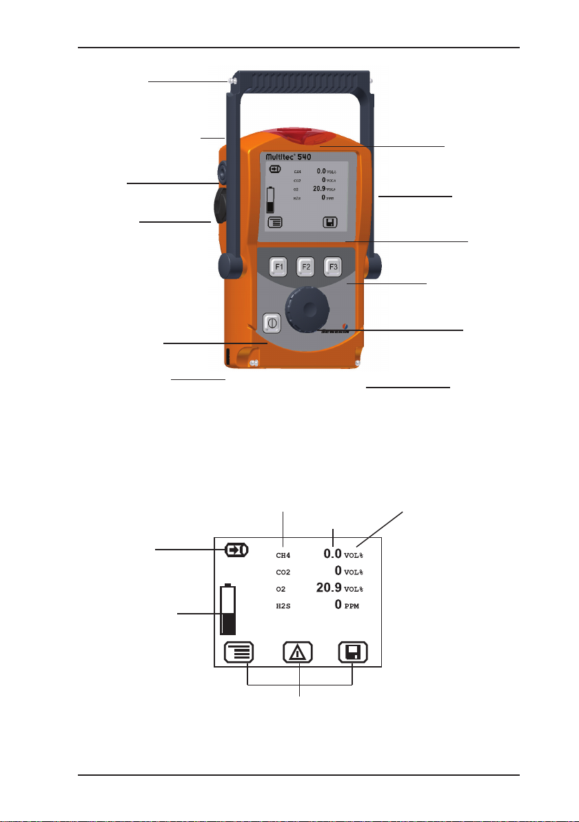
Multitec 540 illustrated
Connector
Supporting bracket
Buzzer
USB port
ON/OFF key
Connection for
power supply
Fig. 1: Multitec 540 device overview
Gas measuring
symbol
Gas
Measured
value
Signal light
Gas input
Display
Function keys
Jog dial
Connector
Unit
Capacity of disposable battery/
rechargeable
battery
Fig. 2: Multitec 540 display
Current assignment of
function keys F1 – F3
Page 4
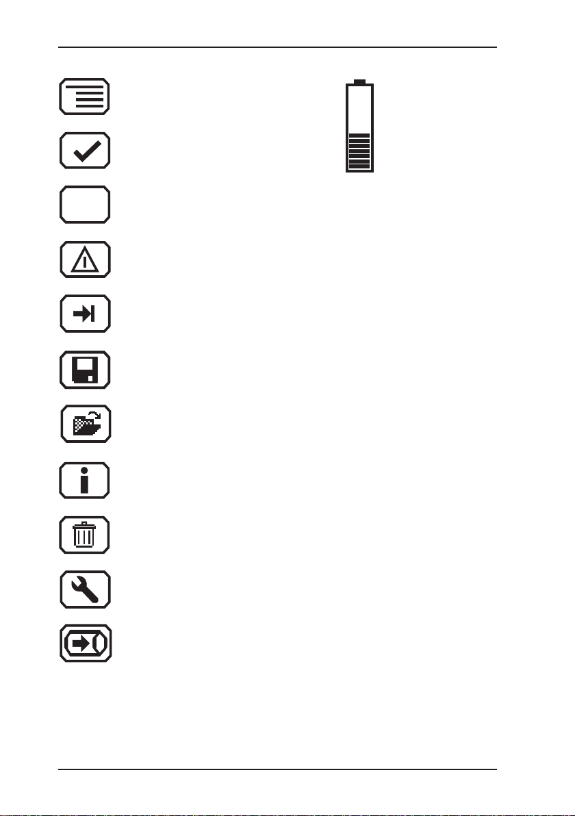
Display symbols
Esc
Menu
OK
Cancel
Perform device inspection
Tab
(jump to next input eld)
Save
Open stored
comment/inspector
Battery
capacity
Information
Clear
Fault
Measure gas
Page 5

Operating Instructions
Multitec® 540
01.08.2011 – V1.XXX – 105832 – en
Page 6
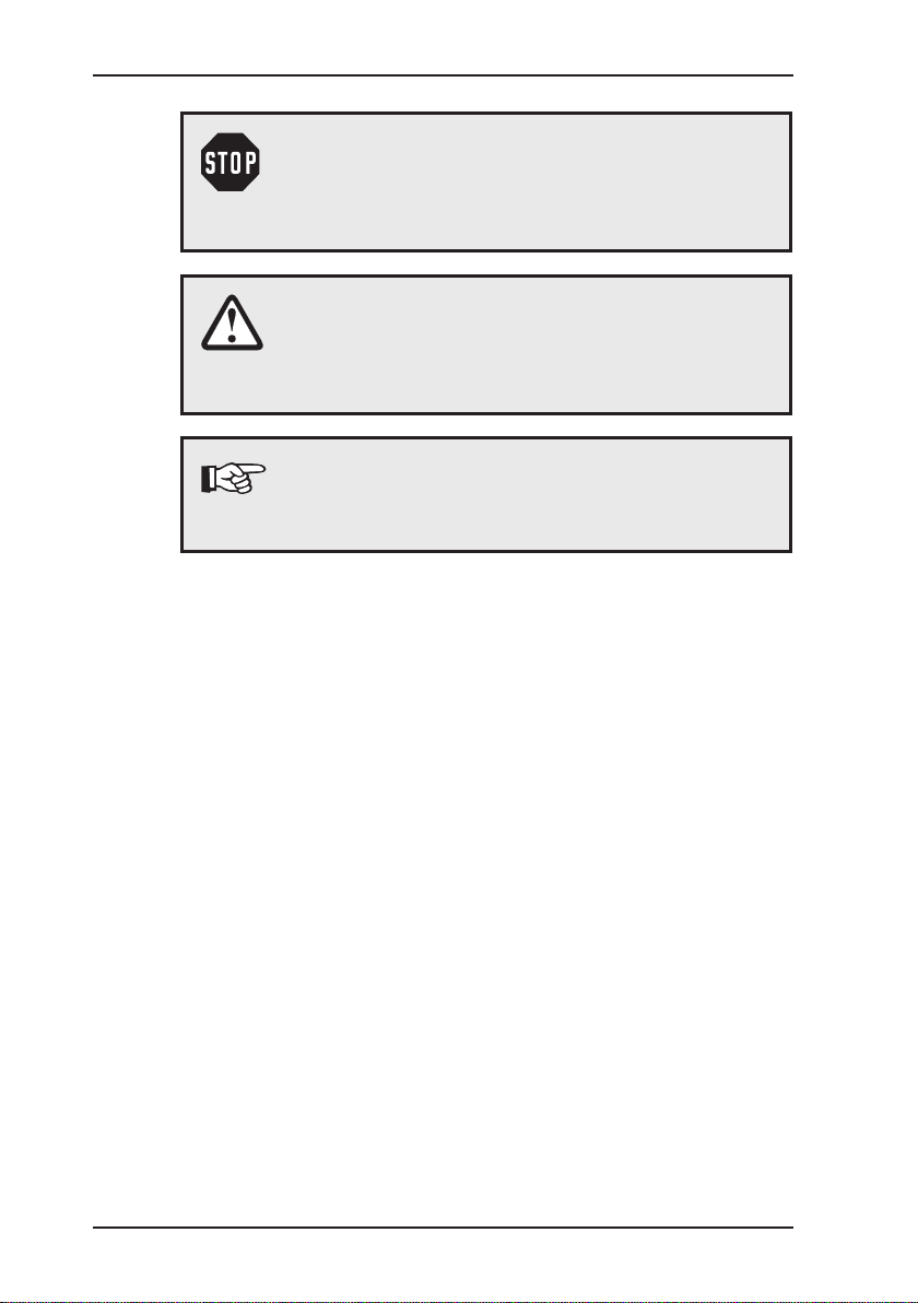
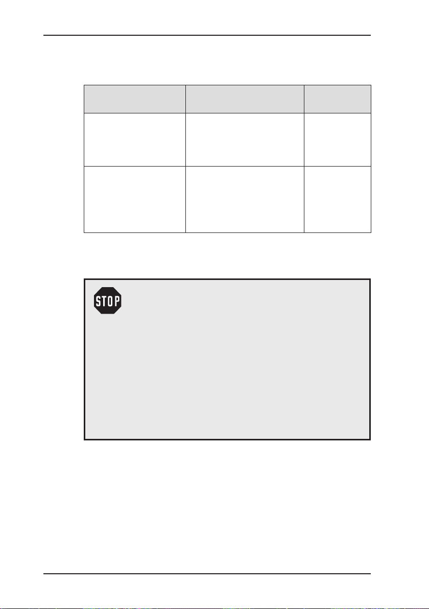
Symbols used
/…/ Reference to standards, guidelines and regulations
CAUTION! Danger of injuries!
This symbol refers to important safety instructions.
Adhere strictly to these instructions to avoid inju-
ries!
CAUTION! Danger of damages!
This symbol refers to important safety instructions.
Adhere strictly to these instructions to avoid mate-
rial damages!
Note:
This symbol refers to information and useful tips which
are exceeding the basic operating procedures.
(see bibliography in Section 7.11)
Page 7

Contents Page
1 General .....................................................................................1
1.1 Warranty ...................................................................................1
1.2 Purpose ..................................................................................... 2
1.3 Intended use .............................................................................3
1.4 General safety information ........................................................4
2 Features ...................................................................................5
2.1 Visual and audible signals .........................................................5
2.2 Sensors .....................................................................................5
2.3 Explosion protection .................................................................. 6
3 Operation .................................................................................7
3.1 General information on operation .............................................. 7
3.1.1 Keys and jog dial .................................................................... 7
3.1.2 Selecting / exiting menus and menu items .............................. 8
3.1.3 Switching on the device .........................................................8
3.1.4 Differences between measuring mode and settings mode ..10
3.2 Measuring mode ..................................................................... 11
3.2.1 Accessing the menu (measuring mode menu structure) ...... 11
3.2.2 Zero point ............................................................................. 11
3.2.3 Gas measuring ..................................................................... 12
3.2.4 Settings ................................................................................12
3.2.5 Saving a measurement ........................................................12
3.2.6 Protocols ..............................................................................13
3.2.7 Device inspection ................................................................. 14
3.2.8 Device info ...........................................................................14
3.3 Settings ...................................................................................15
3.3.1 Opening Settings ..................................................................15
3.3.2 Settings menu structure .......................................................16
3.3.3 Adjustment ...........................................................................17
3.3.4 System .................................................................................18
3.3.5 Date/time .............................................................................. 19
3.3.6 Memory ................................................................................19
4 Power supply ......................................................................... 20
4.1 Suitable disposable/rechargeable battery types .....................20
4.2 Operation with rechargeable batteries ....................................21
4.2.1 Charging ...............................................................................21
I
Page 8

Contents Page
4.2.2 Rechargeable battery servicing ............................................22
4.3 Battery alarm ........................................................................... 22
4.4 Replacing disposable/rechargeable batteries .........................23
5 Maintenance ..........................................................................24
5.1 Device inspection ....................................................................24
5.1.1 General information on the device inspection ...................... 24
5.1.1.1 Scope ................................................................................ 24
5.1.1.2 Frequency ......................................................................... 24
5.1.1.3 Documentation .................................................................. 24
5.1.1.4 Integrated device inspection .............................................25
5.1.1.5 Sequence .......................................................................... 26
5.1.2 Performing the device inspection ......................................... 26
5.1.2.1 Accessing the device inspection ....................................... 26
5.1.2.2 Concluding the device inspection......................................27
5.1.3 Testing the general status ....................................................29
5.1.3.1 Housing ............................................................................. 29
5.1.3.2 Signals ..............................................................................29
5.1.3.3 Probe.................................................................................29
5.1.3.4 Filter ..................................................................................30
5.1.3.5 Pump ................................................................................. 30
5.1.4 Testing indication accuracy with supply of fresh air .............31
5.1.5 Testing indication accuracy with supply of test gas .............. 31
5.2 Adjustment ..............................................................................33
5.2.1 Scope ................................................................................... 33
5.2.2 Preparation ...........................................................................33
5.2.3 Carry out adjustment ............................................................ 33
5.2.3.1 Adjusting the zero point.....................................................34
5.2.3.2 Adjusting sensitivity ........................................................... 34
5.2.4 Carrying out oxygen adjustment ..........................................35
5.2.4.1 Adjusting the zero point for oxygen ................................... 35
5.2.4.2 Adjusting the sensitivity for oxygen ................................... 36
5.3 Servicing .................................................................................37
6 Faults ......................................................................................38
7 Appendix ................................................................................39
7.1 Specications and permitted operating conditions .................. 39
7.2 Limit values for the device inspection .....................................40
II
Page 9

Contents Page
7.3 Memory capacity .....................................................................40
7.4 Sensors ...................................................................................41
7.4.1 Infra red sensors (IR) ...........................................................41
7.4.1.1 Methane CH
.................................................................... 41
4
7.4.1.2 Carbon dioxide CO2 .........................................................41
7.4.2 Electrochemical sensors (EC) .............................................. 42
7.4.2.1 Oxygen O2 ........................................................................ 42
7.4.2.2 Hydrogen sulphide H2S ..................................................... 42
7.5 Technical information ..............................................................43
7.5.1 Identication sticker (back of device) ...................................43
7.5.2 Cleaning ............................................................................... 43
7.5.3 Electrostatic charge ..............................................................43
7.6 Accessories: ............................................................................ 44
7.7 Declaration of conformity ........................................................50
7.8 Inspection protocol ..................................................................51
7.9 Advice on disposal ..................................................................52
7.10 Terminology and abbreviations ...............................................53
7.11 Referenced documents ........................................................... 54
8 Index .......................................................................................55
III
Page 10

1 General
1.1 Warranty
The following instructions must be complied with in order for any
warranty to be applicable regarding functionality and safe operation of this equipment.
Hermann Sewerin GmbH cannot be held responsible for any dam-
ages resulting from non-compliance with these instructions. The
warranty and liability provisions of the terms of sale and delivery
of Hermann Sewerin GmbH are not affected by the information
given below.
z Do not operate this product until you have read and understood
the relevant operating instructions.
z The product must only be used for its intended purpose.
z Repairs must only be carried out by a specialist technician or
by other suitably trained personnel.
z Changes or modications to this product must not be carried
out without approval from Hermann Sewerin GmbH. The manufacturer cannot be held responsible for damages if unapproved
modications have been made.
z Only accessories supplied by Hermann Sewerin GmbH may
be used with this product.
z All repairs must be carried out using replacement parts that
have been approved by Hermann Sewerin GmbH.
z Only use the appropriate type of disposable/rechargeable bat-
tery, otherwise the device will not be explosion-proof.
z The manufacturer reserves the right to make technical modi-
cations in the course of further development.
1 General
Generally applicable safety and accident-prevention regulations
must be complied with, in addition to the information provided in
this manual.
1
Page 11
1 General
1.2 Purpose
The Multitec 540 is a gas measuring device for monitoring gas
mixtures that are formed in biological processes (biogas, landll
gas). It measures the concentration of several gases in the gas
mixture simultaneously. The device is ideal for use in waste dis-
posal sites, sewage plants and biogas plants.
The Multitec 540 is tted with infrared sensors for measuring
methane CH
be tted with electrochemical sensors.
and carbon dioxide CO2 as standard. It can also
4
Note:
These operating instructions refer to the Multitec 540
with all additional equipment. They explain the functions of rmware version 1.XXX. The manufac-
turer reserves the right to make technical changes.
All descriptions refer to the device as delivered (factory settings).
2
Page 12

1.3 Intended use
This device is intended for professional residential and commercial
use including small rms and commercial operations. The appro-
priate specialist knowledge is required to operate the device.
The device may be used to measure the following gases (depending on the sensors tted).
z Methane CH
z Carbon dioxide CO
z Oxygen O
z Hydrogen sulphide H2S
If the device is used in closed spaces these must be well ventilated.
It should not be used for:
z Warning of dangerous gas concentrations
z Monitoring liquids
The device can be used up to a temperature of 40 ºC. However,
high temperatures reduce the lifetime of the sensors and rechargeable batteries.
If a device with an electrochemical sensor is exposed to concentrations above the measuring range limit, this can reduce the
lifetime of the sensor.
1 General
4
2
2
3
Page 13

1 General
1.4 General safety information
z The Multitec 540 is a gas measuring device as opposed to a
gas warning instrument. It does not, therefore, warn of dangerous toxic and explosive gas concentrations or lack of oxygen. If
you suspect dangerous gas concentrations, always take along
a gas warning instrument too.
z Observe the relevant safety regulations when working at agri-
cultural biogas plants/1/.
z The work area must be well ventilated.
z The device has been tested to ensure that it is explosion-proof
in accordance with European standards (CENELEC).
z Do not use this device in oxygen-enriched atmospheres, oth-
erwise it will not be explosion-proof.
z Only probe hoses with a hydrophobic lter may be used.
Exception:
If the probe has a built-in hydrophobic lter, the hose does not
require any other lters.
z Devices may only be tested with test gases in well ventilated
areas or outdoors. Test gases must be handled in a profes-
sional manner.
z Always carry out a device inspection (see Section 5.1) after
the device has suffered an impact (for example, if dropped
accidentally).
z The device complies with the limits of the EMC directive. Al-
ways observe the information in the manuals of (mobile) radio equipment when using the device close to (mobile) radio
equipment.
CAUTION!
Follow the advice regarding explosion protection
(see Section 2.3).
4
Page 14

2 Features
2.1 Visual and audible signals
The device features two alarms:
z Signal light on top of device
(visual signal)
z Buzzer on side of device (audible signal)
The signals indicate faults (see Section 6). The device also emits
signals when it is switched on and off.
2.2 Sensors
The device features two types of sensor:
z Infrared sensor (IR)
z Electrochemical sensor (EC)
Gas Measuring range Sensors Features
CH
CO
O
H
2
2
0.0 – 100 % vol. IR ×
4
0 – 100 % vol. IR ×
2
0 – 25.0 % vol. EC ○
S 0 – 2000 ppm EC ○
2 Features
× standard
○ optional
5
Page 15
2 Features
2.3 Explosion protection
The device features the following explosion protection:
Explosion-proof
group
II2G Ex d e ib IIB T4 Gb – Methane CH
For the following atmospheres
– Propane C3H
– Butane C4H
4
8
10
When using
Device without TG8 car-
rying bag
– Hydrogen sulphide H2S
II2G Ex d e ib IIC T4 Gb – Methane CH
– Propane C3H
– Butane C4H
4
8
10
Device with
TG8 carrying
bag
– Hydrogen sulphide H2S
– Hydrogen H
2
EC type-examination certicate: TÜV 07 ATEX 553353 X
WARNING!
It is essential to observe the following points to en-
sure that the device is explosion-proof:
– Always open the battery compartment and re-
charge the batteries outside the explosive area.
– Always use the USB port outside the explosive
area.
– Always use the appropriate type of disposable/
rechargeable battery.
– To ensure that the device complies with explo-
sion-proof group IIC with hydrogen H
, it must be
2
used in carrying bag TG8.
6
Page 16

3 Operation
3.1 General information on operation
3.1.1 Keys and jog dial
The ON/OFF key is the only control on the device that does not
change its function.
When switched on, the device is operated using the jog dial and
function keys to navigate the display.
Control Action Function
ON/OFF key Press z Switches the device on
z Switches the device off
Function keys
F1, F2, F3
Jog dial Turn z Selects functions, settings,
Press z Variable
z As indicated on the display at
the bottom of the screen
z Function keys may also have
no function assigned in some
cases.
measurement data, etc.
z Modies values
Press z Opens the next program level
(e. g. menu item, function,
measurement data, selectable
values)
z Applies values
3 Operation
7
Page 17
3 Operation
3.1.2 Selecting / exiting menus and menu items
Functions and settings etc. are selected via the main menu (for
short: menu). This menu has submenus and menu items. Refer
to Section 3.2.1 for information on accessing the main menu.
Selecting submenus / menu items
Submenus and menu items are selected and opened using the
jog dial and/or the function keys (see Section 3.1.1).
The name of the selected menu or menu item is always shown
at the top left of the display.
Exiting menus / menu items
There are generally two ways to exit open menus / menu items
and return to the next level up:
z Press Esc.
z Select Back from the menu.
3.1.3 Switching on the device
Note:
Always switch the device on with fresh air.
z Press the ON/OFF key. The device switches on.
A visual and audible signal conrm that the device has been
switched on. The display and the pump come on.
The start screen appears on the display.
8
Page 18
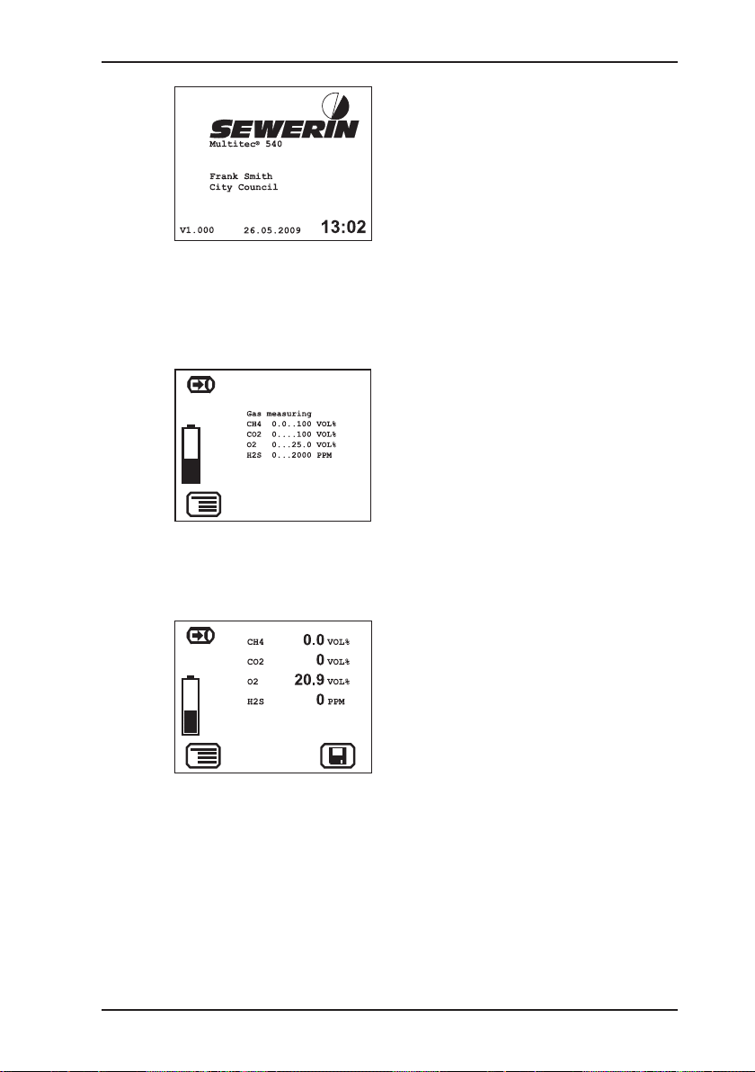
3 Operation
Display:
– Device type: Multitec 540
– User:
Frank Smith
City council
– Firmware version: V1.000
– Date and time
Fig. 3: Start screen
An overview of the gases that can be detected will then appear
briey.
Display:
– Symbol: Gas measuring
– Detectable gases
– Measurement ranges
– Battery capacity
Fig. 4: Overview of detectable gases
The device switches to measuring mode.
Display:
– Current readings: zero when
device is switched on with fresh
air
Fig. 5: Measuring mode – Display of current readings
The device is ready for use.
9
Page 19

3 Operation
3.1.4 Differences between measuring mode and settings mode
The device is operated in two modes:
z Measuring mode (see Section 3.2)
Measurements are taken in measuring mode. All functions
needed to take readings can be accessed from one menu.
z Settings (see Section 3.3)
The device settings can be changed in settings mode. Information about the device can also be retrieved. Readings cannot
be taken in settings mode.
Settings are accessed via the menu in measuring mode. The
settings are access-protected by a PIN code.
10
Page 20

3 Operation
3.2 Measuring mode
When switched on (see Section 3.1.3), the device is in measuring
mode. In measuring mode, the current measurements are always
displayed (see Fig. 5).
3.2.1 Accessing the menu (measuring mode menu structure) In measuring mode the menu can be accessed with F1.
Zero point
Gas measuring
Settings
Save measurement
Protocol
Device inspection
Device information
Exit
Fig. 6: Menu with submenus (menu items)
Device inspection only appears in the menu when the integrated
device inspection is switched on (see Section 5.1.1.4).
3.2.2 Zero point
The zero point only has to be set manually if the displayed fresh air
measurement is not zero after the end of the warm-up period.
Requirements for correct setting of the zero point
− Device was switched on with fresh air.
− Device continues to draw in fresh air.
z Press Menu.
z Select Zero point from the menu. The values are automatically
adjusted. The device returns to measuring mode.
11
Page 21

3 Operation
Fresh air contains:
− Oxygen O
: 20.9 % vol.
2
− Carbon dioxide CO
After the zero point has been set, 20.9 % vol. will therefore appear for oxygen. Due to the resolution of the measuring range
the value for carbon dioxide will be 0 % vol..
The manual zero point setting is not saved. The zero point can
be corrected as often as zero point deviations occur (see Section 5 .2).
3.2.3 Gas measuring
You can nd an overview of the detectable gases under Gas
measuring in the menu (see Fig. 4). The device automatically
returns to measuring mode.
3.2.4 Settings
You can change the device settings and access information about
the device under Settings in the menu (see Section 3.3).
: 0.04 % vol.
2
3.2.5 Saving a measurement The current measurement values are saved using Save measu-
rement. Measurement les can be displayed on a computer using
a readout program.
The program is available at www.sewerin.com.
z Press Menu.
z Select Save measurement from the menu.
Note:
If the current measurement values are stable, the
Save symbol will appear. You can then also save
the measurement values using the appropriate
function key.
12
Page 22

3 Operation
z If necessary, enter a comment on the measurement.
− Select the characters required using the jog dial. Conrm
each character using the jog dial.
OR
− Press Open saved comment. A list of the saved comments
will appear. Select the desired comment. Open the comment
with OK.
Note:
Comment entries are saved automatically. The last
10 comments entered (maximum) will be saved.
Once the rst comment has been entered, the Open
saved comment function will become available.
z Conrm your entry/selection with OK. The comment is saved
together with the protocol name (date, time).
Note:
If you do not need to enter a comment, you can also
skip the input eld by pressing Esc. The measurement is still saved.
3.2.6 Protocols You can retrieve or clear protocols of saved data under the Pro-
tocols menu item. When saved, the protocols are assigned to
different protocol types.
The following protocol types are available:
z Device inspection
z Measurements
Protocols can only be cleared individually.
You can nd information on how to clear all protocols of the same
protocol type in Section 3.3.6.
13
Page 23

3 Operation
3.2.7 Device inspection Device inspection only appears in the menu when the integrated
device inspection is switched on. The device inspection can be
used to check the general status and the indication accuracies.
Note:
The integrated device inspection is switched off in
the factory settings. More detailed information about
the device inspection can be found in Section 5.1.
If the integrated device inspection is switched on, the device will
remind you every 3 months to perform a device inspection.
The symbol will appear when the device inspection
is due. It is visible in the display until the complete
integrated device inspection has been carried out
successfully.
3.2.8 Device info The following device information is shown under Device infor-
mation in the menu.
z Installed electrochemical sensors:
gas, installation date, warranted/expected lifetime
z Firmware:
version, date
z Service:
date of the last service, date of the next service
14
Page 24

3.3 Settings
The following menus and menu items are included under Settings
(see Sections 3.3.3 to 3.3.6):
z Adjustment
z System
z Date/time
z Memory
You can nd information on selecting and exiting menus and menu
items in Section 3.1.2.
3.3.1 Opening Settings
z Press Menu.
z Select the Settings menu item.
Access is protected by a PIN code. The default setting is always
PIN code 0001.
After opening Settings, you can change the PIN code (see Section 3.3.4). It is advisable to set a different PIN code after initial
start-up, so only authorised personnel have access to the settings.
3 Operation
z Enter the PIN code from left to right. The active digit is always
displayed with a black background.
Digit To change: To conrm:
1st digit
Push the jog dial.
2nd digit Push the jog dial.
3rd digit Push the jog dial.
Turn the jog dial.
4th digit
If the PIN code has been entered correctly, the Settings menu
will appear once the last digit has been conrmed (see Fig. 7).
Otherwise the device will revert to measuring mode.
15
Page 25

3 Operation
Adjustment
System
Date/time
Memory
Exit
Fig. 7: Settings menu
3.3.2 Settings menu structure
Settings Adjustment Adjustment CH4
Measuring mode
PIN Code
Adjustment CO2
Adjustment O2
Adjustment H2S
Test gas
Inspection OK
Exit
System PIN Code
Service interval
Display
Battery
Autostart
Device inspection
Reset
Language
Exit
Date/time
Memory Clear
Interval
Memory mode
Exit
Exit
Fig. 8: Multitec 540 Settings menu structure
16
Note:
The number and names of available menu items
depend on the device model and optional additional
equipment.
Page 26

3.3.3 Adjustment
The Adjustment menu is used to set the sensors.
More detailed information about adjustment can be found in Section 5.2.
CH4 adjustment
Adjusts the infrared sensor for methane CH
range.
CO2 adjustment
Used to adjust the infrared sensor for carbon dioxide CO2 in the
% vol. range.
3 Operation
WARNING!
The device must only be adjusted by specialist
technicians in well ventilated rooms or in the open
air. Incorrect adjustment can lead to incorrect measurement results.
in the % vol.
4
O2 adjustment
Adjusts the electrochemical sensor for oxygen O2 in the % vol.
range.
H2S adjustment
Adjusts the electrochemical sensor for hydrogen sulphide H2S
in the ppm range.
Test gas
Adjusts the concentration of the test gases used.
Inspection OK
Conrms the device is in proper working order. This extends the
service interval.
17
Page 27

3 Operation
3.3.4 System
General information and specications for operation are set in
the System menu.
PIN code
Used to change or reset the PIN code.
Service interval
Specify the regular inspections/maintenance required for the device. You can also activate the automatic switch-off function once
the set interval has passed.
Note:
If the PIN code is set to 0000, you will not be asked
to enter the PIN code. The settings can then be accessed by anyone.
If you lose the PIN code, you must contact SEWERIN
Service.
18
Display
Used to set how long the display remains illuminated after any
button is pressed as well as the display contrast.
Battery
Used to set the type of disposable/rechargeable battery used.
CAUTION!
The disposable/rechargeable battery type setting
must always be correct to prevent damage to the
device.
Autostart
This setting cannot be changed.
Page 28

Device inspection
Switches the integrated device inspection on and off.
Reset
Use to reset the device settings to the factory settings.
Language
Sets the language.
3.3.5 Date/time
Used to set the time, day, month, and year. There are two formats
available for the date.
3.3.6 Memory
The Memory menu is used to specify how measurement data
and protocols are handled.
Clear
Used to clear protocols.
The two different protocol types must each be cleared separately.
All protocols in one protocol type are cleared at once.
You can nd information on clearing individual protocols in Section 3.2.6.
3 Operation
Interval
Set the interval at which measurement data is automatically
saved.
Memory mode
Switches between ring memory and stack memory.
19
Page 29

4 Power supply
4 Power supply
This device can be operated using:
z Disposable (non-rechargeable) alkaline batteries
z Rechargeable NiMH batteries
The device comes with nickel metal hydride rechargeable batteries. The corresponding settings are stored.
WARNING!
The device must not be used with leaking batteries. Replace the disposable/rechargeable batteries.
Clean the battery compartment (and, if necessary,
the device) before inserting the new disposable/
rechargeable batteries.
4.1 Suitable disposable/rechargeable battery types
WARNING!
To ensure that the device remains explosion-proof
as per /6/, only the following disposable/recharge-
able batteries may be used:
– Batteries supplied by SEWERIN
– Others offered by SEWERIN, provided observ-
ance as per /3/ is guaranteed.
The battery types used in one battery compartment
must always be identical in terms of sort (disposable/
rechargeable), capacity and manufacturer.
20
Disposable battery requirements
z Alkaline disposable batteries
z Battery size: AA, Type: LR6 as per /4/
z The creepage distance and air gap between the poles must
not be less than 0.5 mm in accordance with /3/.
Page 30

Rechargeable battery requirements
z NiMH rechargeable batteries
z Battery size: AA, Type: HR6 as per /5/
z The creepage distance and air gap between the poles must
not be less than 0.5 mm in accordance with /3/.
z The rechargeable batteries must be fast charging (I > 1.25 A)
and remain within the temperature range.
CAUTION!
A device operated with disposable alkaline batteries
cannot be charged. A notice to this effect is shown
on the display.
4.2 Operation with rechargeable batteries
The operating time of the device depends on the battery capacity.
If the device is not used or not kept in the docking station, the
rechargeable batteries will lose their charge after 30 days at the
latest ( self-discharge).
4 Power supply
4.2.1 Charging
The device can be charged via:
z Connection for power supply
z Docking station TG8
For charging you will need either:
z AC/DC adapter M4
z Vehicle cable M4
Please note the following points:
z The device/docking station must not be directly connected to a
24-V on-board power supply in the vehicle. The voltage is too
high for the charging process.
z The battery should be charged at approximately room tem-
perature.
21
Page 31

4 Power supply
z Short operating times and long periods out of use can reduce
the available battery capacity (memory effect).
4.2.2 Rechargeable battery servicing
If the device is not used for a long period of time, it is recommended to fully discharge the battery before recharging it again.
WARNING!
The device must only be discharged outside of the
explosive area.
z Connect the device (switched on) to the power supply via the
side connection
OR
z Place the device (switched on) into the docking station.
The rechargeable batteries will be fully discharged. Once the
device has been discharged, it will automatically switch to
charging mode.
A full discharging and recharging process takes approx. 11 hours
(8 hrs discharging + 3 hrs. recharging). The duration depends
on the capacity of the batteries used.
4.3 Battery alarm
As soon as the remaining capacity of the disposable/rechargeable battery gets low, a battery alarm will go off:
Level 1: Disposable/rechargeable battery almost empty:
Level 2: Disposable/rechargeable battery empty:
22
– Capacity of disposable/rechargeable battery
symbol ashes
– Audible signal (one-off)
– Remaining operating time: approx. 15 min
– Blank display apart from Capacity of disposable
battery/rechargeable battery symbol
– Continuous audible signal
– Measuring mode unavailable
– Device shuts off
Page 32

4.4 Replacing disposable/rechargeable batteries
WARNING!
Disposable/rechargeable batteries must always be
replaced outside of the explosive area.
A 2.5 mm Allen key (supplied) is required to open the battery
compartment on the back of the device.
z Loosen the two screws securing the battery compartment.
Remove the screws by repeatedly turning each one a short
distance in alternation; this ensures that the battery compartment does not twist.
z Lift out the battery compartment.
z Remove the disposable/rechargeable batteries and insert new
ones. Ensure that the batteries are inserted with the correct
polarity.
z Replace the battery compartment so it ts neatly into place and
secure rmly with the screws.
z When you switch the device back on again, you will be asked
which battery type is in use. Enter the correct battery type.
If it takes longer than 120 seconds to change the batteries, the
date and time will have to be reset the next time you switch the
device on. All the other data will be saved.
4 Power supply
23
Page 33

5 Maintenance
5 Maintenance
In accordance with the legal regulations, device maintenance
comprises the following elements:
z Device inspection including test of indication accuracy
z Adjustment
z Servicing
All inspections must be documented. The documentation must
be retained for at least one year.
5.1 Device inspection
5.1.1 General information on the device inspection
5.1.1.1 Scope
The device inspection includes the following tests:
z Analysis of the general status (see Section 5.1.3)
z Test of the indication accuracy with supply of fresh air (see
Section 5.1.4)
z Test of the indication accuracy with supply of test gas (see
Section 5.1.5)
5.1.1.2 Frequency
The device inspection must be carried out at intervals ranging
from once a week to every six months /2/.
If the integrated device inspection is switched on, the device will
remind you every 3 months to perform a device inspection.
5.1.1.3 Documentation
The device inspection procedure must be documented. There
are two ways of doing this:
z On paper
z Saved electronically supported by the device (integrated de-
vice inspection)
24
Page 34

Only the integrated device inspection is described in these operating instructions.
Note:
The device inspection must be documented on paper if the integrated device inspection is switched
off.
5.1.1.4 Integrated device inspection
Note:
The integrated device inspection is switched off in
the factory settings.
The results of the integrated device inspection are stored in the
device as a protocol. They can be displayed on a computer using
a readout program.
This symbol appears in the display when a device
inspection is due. It is visible in the display until the
complete integrated device inspection has been carried out successfully. If the device inspection was
completed but the device failed on some points (not
OK), the symbol will remain visible.
5 Maintenance
Switching on the device inspection
z Press Menu.
z Select Settings.
z Enter your PIN code.
z Select System.
z Select device inspection.
z Select Yes.
z Apply the setting with OK.
z Exit the Settings with Back.
25
Page 35

5 Maintenance
5.1.1.5 Sequence
You can carry out the tests that make up the device inspection in
any order you wish. You can repeat the tests as often as you wish
provided you have not yet concluded the device inspection.
5.1.2 Performing the device inspection
5.1.2.1 Accessing the device inspection
The device is in measuring mode.
z Press Device inspection.
The Device inspection menu appears.
Note:
If the device inspection is accessed via the menu,
you must also conrm Bar holes/measuring in the
menu with OK.
General status
Fresh air
Test gas CH4
Test gas CO2
Test gas H2S
Fig. 9: Device inspection menu
26
Please note that Test gas H2S only appears in the menu if the
device is congured for this particular gas type.
z Select a test from the menu (General status, Fresh air, Test
gas…).
Note:
The number and names of the available menu items
depend on the device features.
Page 36

z Carry out the test.
For detailed information, refer to the following sections:
− General Status Section 5.1.3
− Fresh air Section 5.1.4
− Test gas … Section 5.1.5
5.1.2.2 Concluding the device inspection
After all the tests have been carried out as described in Sections 5.1.3 to 5.1.5, the Save symbol will appear in the display.
The device inspection can be concluded.
z Press Save.
z If necessary enter the name of the inspector.
− Select the characters required using the jog dial. Conrm
each character using the jog dial.
OR
− Press Open saved inspector. A list of the saved inspectors
will appear. Select the desired inspector. Open the inspector with OK.
5 Maintenance
Note:
Inspector entries are saved automatically. The last
10 inspectors entered (maximum) will be saved.
Once the rst inspector has been entered, the Open
saved inspector function will become available.
z Conrm your entry/selection with OK.
z Enter a password if necessary. Select the characters required
using the jog dial. Conrm each character using the jog dial.
z Conrm your entry with OK. The device inspection is saved as
a protocol. A comprehensive overview with the device inspec-
tion results is displayed.
z Conrm the overview by pressing OK. The device returns to
measuring mode.
27
Page 37

5 Maintenance
The device inspection protocols can be opened at any time (see
Section 3.2.6). The number is limited to a maximum of 40.
Note:
If you do not need to enter an inspector or a password, these input elds can be skipped by pressing Esc. The device inspection is still saved as a
protocol.
28
Page 38

5.1.3 Testing the general status
The general status test is part of the device inspection (see Section 5.1.1.1). It is based on estimations by the user. The following
must be tested:
z Housing
z Signals
z Probe
z Filter
z Pump
The battery charge status and the working condition of the components are automatically tested during the integrated device
inspection.
z Select General status from the Device inspection menu.
z Test all associated subitems as described in Sections 5.1.3.1
to 5.1.3.5.
z Conrm the prompt General status OK? by pressing Yes if
all subitems show no faults during testing. General status OK
appears on the display.
5 Maintenance
5.1.3.1 Housing
z Is the housing free from external damage?
5.1.3.2 Signals
During the integrated device inspection the signals are emitted
at short intervals.
z Can the audible signal be heard?
z Is the visual signal visible?
5.1.3.3 Probe
Probes are accessories. They must only be tested if they are
likely to be used in the course of the work day.
z Are the probes free from external damage?
Probe hoses are tested with a simple leak-tightness check.
29
Page 39

5 Maintenance
z Connect the probe hose to the gas input.
z Seal the free end of the probe hose.
An error message should appear after approximately 10 seconds. This indicates that the probe hose is in good condition.
5.1.3.4 Filter
Thene dust lter is located behind the gas input. It is tested by
means of a visual inspection.
z Unscrew the gas input.
z Remove the ne dust lter.
z Check that there is no dirt in the ne dust lter.
As soon as there are any signs of depositing, the lter must
be replaced. If you do not replace the lter, you must reinsert
it exactly as it was removed.
5.1.3.5 Pump
The pump function is tested with a simple leak check.
z Seal the gas input.
After a maximum of 10 seconds an error message should appear. This indicates that the pump is working correctly.
If the error message does not appear, the pump may be faulty.
The device must be tested by SEWERIN Service.
z Release the gas input again.
After approximately seconds, the error message should disappear again. Otherwise there is an error (see Section 6).
30
Page 40

5 Maintenance
5.1.4 Testing indication accuracy with supply of fresh air
The indication accuracy with supply of fresh air test is part of the
device inspection (see Section 5.1.1.1).
Ensure that the fresh air used for testing is sufciently pure.
z Select Fresh air from the Device inspection menu.
z Wait until the displayed readings are stable. A Status: OK
message appears.
z Press OK to conrm. Fresh air OK appears on the display.
If the Status: OK message does not appear within a reasonable
amount of time, the air inow does not correspond to the limit
values stored in the device (see Section 7.2). Move the device
somewhere else and repeat the test.
If the Status: OK message still does not appear when the test is
repeated, the device must be re-adjusted (see Section 5.2).
5.1.5 Testing indication accuracy with supply of test gas
The indication accuracy with supply of test gas test is part of the
device inspection (see Section 5.1.1.1).
z Select the gas to be tested (test gas CH4, test gas CO2, test
gas H2S) from the Device inspection menu.
z Check whether the test gas concentration specied by the
device matches the test gas you intend to use. Press Infor-
mation.
z Add the gas to be tested. Connect the test gas to the gas in-
put.
z Wait until the displayed readings are stable. A Status: OK
message appears.
z Press OK to conrm.
z Remove the test gas.
If the Status: OK message does not appear within a reasonable
amount of time, the following causes are possible:
31
Page 41

5 Maintenance
Cause Corrective action
Connections leaking Repeat check, checking for the
Measurement values outside
the specied limit values
(see Section 7.2)
Changing the test gas
If no test gas with the specied concentrations is available for the
test, the values can be changed accordingly under Test gas in
the adjustment menu (see section 3.3.3).
seal on the connections
Adjustment required
(see Section 5.2)
Note:
The Test gas OK message only appears when all
the test gases specied in the device inspection
have been successfully tested.
32
Page 42

5.2 Adjustment
5.2.1 Scope
The following are adjusted:
z Zero point
z Measuring range sensitivity
It is not essential to adjust all gases during adjustment. Every gas
must be adjusted separately.
5 Maintenance
WARNING!
The device must only be adjusted by specialist
technicians in well ventilated rooms or in the open
air. Incorrect adjustment can lead to incorrect measurement results.
CAUTION!
Always adjust the zero point rst, followed by the
sensitivity.
5.2.2 Preparation
Carrying out an adjustment always takes some time. Leave yourself plenty of time to prepare the necessary steps of the proce-
dure. Have all necessary tools available. Let the device run for
several minutes, to guarantee, for example, that the temperature
is right.
5.2.3 Carry out adjustment
Adjustment of the zero point and the sensitivity is carried out following the same procedure for all gases (see Sections 5.2.3.1
and 5.2.3.2). The adjustment of oxygen is an exception. For this
reason it is described separately (see Section 5.2.4).
33
Page 43

5 Maintenance
You can access detailed information on the adjustment of the various gases (for example, test gas,
installation date of the sensor, or date of the last ad-
justment) under Information.
This symbol appears after the respective Adjust-
ment … has been selected from the menu.
5.2.3.1 Adjusting the zero point
For all gases except oxygen O
ing the same procedure.
Note:
When adjusting the zero point of carbon dioxide CO
, a carbon dioxide lter must be used.
2
z Select the desired adjustment from the Adjustment menu
(for example, CH4 adjustment).
z Wait at least 1 minute. The displayed reading must be stable.
z Select Zero point from the menu (select and conrm with OK).
This adjusts the zero point. The reading shows zero (0.00 %
vol. or 0 ppm).
, the zero point is adjusted follow-
2
5.2.3.2 Adjusting sensitivity
For all gases except oxygen O
ing the same procedure.
A test set (such as SPE VOL) is required for adjusting the sensitivity.
Note:
When adjusting the sensitivity, never use a carbon
dioxide lter.
34
, the sensitivity is adjusted follow-
2
Page 44

z Connect the device to the test set.
To do so, follow the steps indicated in the test set operating
instructions.
z Select the desired adjustment from the Adjustment menu
(for example, CH4 adjustment).
z Select the menu item that species the sensitivity to be tested
(for example, 100 % VOL CH4). Do not yet conrm with
OK.
z Press and hold the release button on the test set. The test gas
is added. Do not let go of the release button.
z Wait at least 1 minute. The displayed reading must be stable.
z Press OK to conrm. The device is adjusted. The reading shows
the specied value (e. g. 100 % vol. CH
z Let go of the release button on the test set.
5.2.4 Carrying out oxygen adjustment
As oxygen is a component of fresh air, the procedure for adjusting
oxygen is different than the procedure for all other gases.
5 Maintenance
).
4
5.2.4.1 Adjusting the zero point for oxygen
The zero point for oxygen must be adjusted using an inert gas
which contains no oxygen and does not damage the sensor.
For example, suitable test gases include 100 % vol. CH
100 % vol. N2.
A test set (such as SPE VOL) is required for adjusting the zero
point.
z Connect the device to the test set.
To do so, follow the steps indicated in the test set operating
instructions.
z Select Adjustment O2 from the Adjustment menu.
z Select Zero point from the menu. Do not yet conrm with
OK.
z Press and hold the release button on the test set. The test gas
is added. Do not let go of the release button.
z Wait at least 1 minute. The displayed reading must be stable.
or
4
35
Page 45

5 Maintenance
z Press OK to conrm. The device is adjusted. The reading shows
zero (0.0 % vol.).
z Let go of the release button on the test set.
5.2.4.2 Adjusting the sensitivity for oxygen
The sensitivity of oxygen is adjusted with fresh air.
z Select Adjustment O2 from the Adjustment menu.
z Wait until the displayed reading is stable. (The reading may
still ash.)
z Select 20.9 % VOL (fresh air) from the menu (select and con-
rm with OK). This adjusts the sensitivity. The reading shows
20.9 % vol.
36
Page 46

5.3 Servicing
The device must only be serviced and repaired by SEWERIN
Service.
z Send the device to SEWERIN for repairs and for annual main-
tenance.
Fig. 10: Inspection plate
5 Maintenance
Note:
If there is a service agreement in place, the device
can be serviced by the mobile maintenance service.
The inspection plate on the device shows conrmation of the last maintenance and the next
scheduled maintenance (for example, 5/02 = May
2002).
37
Page 47

6 Faults
6 Faults
If a fault occurs during operation, an error message will appear
on the screen.
Error messages are displayed in the order in which they occur.
Up to 5 errors can be displayed. Error messages continue to be
displayed until the error is corrected.
Overview of possible error messages
Error code Error message on the
display
9 No calibration
IR sensor adjustment
10 Adjustment failed
Test gas
52 XFLASH
SEWERIN Service
59 Error unknown
SEWERIN Service
62 IR sensor Error can only be corrected by
100 Pump error
Probe / lter
200 I2C HOST – IR
SEWERIN Service
201 I2C HOST – EC
SEWERIN Service
202 I2C HOST – EX
SEWERIN Service
Error correction
CH
adjustment or CO2 adjustment
4
required (see Section 5.2)
Check test gas
Error can only be corrected by
SEWERIN Service
Error can only be corrected by
SEWERIN Service
SEWERIN Service
Check all lters, probes and hose
connections for porosity and dirt
Error can only be corrected by
SEWERIN Service
Error can only be corrected by
SEWERIN Service
Error can only be corrected by
SEWERIN Service
38
Page 48

7 Appendix
7.1 Specications and permitted operating conditions
7 Appendix
Dimensions
(W × D × H):
Approx. 148 × 57 × 205 mm
Approx. 148 × 57 × 253 mm with supporting
bracket
Weight Approx. 1000 g,
depending on equipment
Operating position: Any
Protection rating IP54
Power supply: 4 cells, either:
– Rechargeable batteries: NiMH
– Disposable batteries: Alkaline
Operating time At least 8 h
Charging time for re-
chargeable batteries:
Approx. 3 h (fully charged)
depending on capacity
Charging voltage: 12 V DC (max. 1 A)
Operating temperature: -20 ºC – +40 ºC
Storage temperature: -25 ºC – +60 ºC
Pressure: 800 – 1100 hPa
Permissible relative
5 – 90 % r.h., non-condensing
humidity:
Sensors: – IR for CH
, CO
4
2
Optional:
– EC for O2, H2S
Warm-up time: – < 30 s
– Up to 90 s for EC
PC connection: USB
Data memory: 8 MB
Display: 320 × 240 pixels
Buzzer: – Frequency: 2.4 kHz
– Volume: 80 dB (A) / 1 m
Signal light: Red
Pump capacity: – Vacuum: > 250 mbar
– Volume ow: Typically 50 l/h ±20 l/h
Pressure at gas input: – 100 mbar, maximum
Operation: – ON/OFF key
– Jog dial
– 3 function keys
39
Page 49

7 Appendix
7.2 Limit values for the device inspection
Gas Zero point Sensitivity
Specication Deviation Specication Deviation
0.00 % vol. ±2 % vol. 100 % vol. ±5 % vol.
CH
4
0 % vol. ±2 % vol. 100 % vol. ±5 % vol.
CO
2
0 % vol. ±0.5 % vol. 20.9 % vol. ±0.5 % vol.
O
2
S 0 ppm ±10 ppm 40 ppm ±10 ppm
H
2
7.3 Memory capacity
The total memory capacity of the device is divided up as follows:
Protocol type Max. storable protocols
Device inspection 40
Measurement 80
40
There is a choice of two memory modes (see Section 3.3.6). The
selected memory mode applies for all protocol types.
Page 50

7.4 Sensors
Note:
Probes increase the stated response times.
7.4.1 Infra red sensors (IR)
7 Appendix
7.4.1.1 Methane CH
4
Type: Infrared sensor
Measuring range: 0 – 100 % vol.
Measuring error CH4: ±1.5 % vol.
Response times: t
Temperature range: -20 ºC – +40 ºC
Interference: All hydrocarbons C
Lifetime:
– Warranted
– Expected
Test gases:
– Zero point
– Sensitivity
7.4.1.2 Carbon dioxide CO2
Type: Infrared sensor
Measuring range: 0 – 100 % vol.
Measuring error: ±1.5 % vol.
Response time: t90 < 20 s
Temperature range: -20 ºC – +40 ºC
Interference: None known
Lifetime:
– Warranted
– Expected
Test gases:
– Zero point
– Sensitivity
< 9 s t90 < 17 s
50
2 years
5 years
Fresh air
100 % vol.
2 years
5 years
Fresh air
100 % vol. CO
2
xHy
41
Page 51

7 Appendix
7.4.2 Electrochemical sensors (EC)
7.4.2.1 Oxygen O
2
Type: Electrochemical sensor
Measuring range: 0 – 25 % vol.
Resolution: 0.1 % vol.
Measuring error: ±3 % or ±0.3. % vol. (±3 digits)
Response time: t
Drift: < 2 % within 3 months
Temperature range: -20 ºC – +40 ºC
Interference: None known
Lifetime:
– Warranted
– Expected
Test gases:
– Zero point
– Sensitivity
7.4.2.2 Hydrogen sulphide H2S
Type: Electrochemical sensor
Measuring range:
– Lower limit
Resolution: 2 ppm
Measuring error: ±3 % or ±6 ppm (±3 digits)
Zero point deviation: 2 ppm
Response time: t
Decay time: t10 < 27 s
Drift: < 10 % within 6 months
Temperature range: -20 ºC – +40 ºC
Interference at 20 ºC
– 100 ppm CO
– 1 % vol. H
– 100 ppm NO
Lifetime:
– Warranted
– Expected
Test gases:
– Zero point
– Sensitivity
2
2
< 15 s
90
2 years
3 years
100 % vol. CH
or 100 % vol. N
4
Fresh air (20.9 % vol.)
0 – 2000 ppm
2 ppm
±4 ppm (long-term stability)
< 30 s
90
Approx. 2 ppm H2S
Approx. 10 ppm H2S
Approx. 4 ppm H2S
1 year
> 2 years
Fresh air
40 ppm H2S
2
42
Page 52

7.5 Technical information
7.5.1 Identication sticker (back of device)
The symbols on the sticker mean the following:
Always open battery compartment outside
the explosive area.
Read the operating instructions.
7.5.2 Cleaning
The device must only be cleaned with a damp cloth.
CAUTION!
Do not use solvents, petrol or cockpit spray containing silicone or similar substances to clean the
device!
7 Appendix
7.5.3 Electrostatic charge
Avoid electrostatically charging the device. Electrostatically
unearthed objects (e. g. including metallic housing without an
earth connection) are not protected against applied charges (e.g.
through dust or dispersed ows).
CAUTION!
To prevent electrostatic charging when working with
hydrogen H
, always use carrying bag TG8.
2
43
Page 53

7 Appendix
7.6 Accessories:
Docking station TG8
Art. no.: LP11-10001
z For charging, operating and
holding one device
z Includes locking mechanism to
prevent unit falling out
z AC/DC adapter or vehicle ca-
ble required for charging and
operation
AC/DC adapter M4
Art. no.: LD10-10001
z 100 – 240 V~ / 12 V=
44
Vehicle cable M4
Art. no.: ZL07-10100
z 12 V= mobile, with built-in fuse
and cigarette lighter adapter
z For mobile use in a vehicle
Vehicle cable M4
Art. no.: ZL07-10000
z 12 V= mounting, includes
built-in fuse and female spade
connectors
z permanently connects unit to
the vehicle electrical system
Page 54

7 Appendix
Vehicle cable M4
Art. no.: ZL09-10000
z 24 V= mounting, includes volt-
age converter and female
spade converters
z permanently connects unit to
the vehicle electrical system
Carrying system "Vario"
Art. no.: 3209-0012
z Two adjustable carrying straps
with quick release buttons and
padded straps
z Can be worn around the neck
or as a chest harness.
Carrying bag TG8
Art. no.: 3204-0040
z Leather, with viewing panel
and openings for connections,
jog dial and securing the carrying systems
z Easily tted thanks to Velcro
fastener
z Can be used in explosive
areas
45
Page 55

7 Appendix
Case TG8-RÜ
Art. no.: ZD29-10000
z With built-in compartments
z Allows for charging from the
outside
z Holds:
– Multitec 540
– Docking station TG8
– AC/DC adapter M4
– Probe hose 1 m, 2 m or 6 m
– Flexible handheld probe
– Bell jar probe
– Pinpointing probe
– Floating probe
– 100 ne dust lters
– etc.
46
Compact case TG8
Art. no.: ZD31-10000
z With built-in compartments
z Holds:
– Multitec 540
– Docking station TG8
– AC/DC adapter M4
– Probe hose 1 m, 2 m or 6 m
– Flexible handheld probe
– Floating probe
– 100 ne dust lters
– etc.
Page 56

7 Appendix
Flexible handheld probe
Art. no.: ZS32-10000
z 360 mm long
z Flexible tip with handle for
leak detection in two-handed
operation
z Probe hose 1 m required
Probe hose
Art. no.: ZS25-10000 (example)
z With hydrophobic filter and
quick connects
z Various lengths available
Gas sample connection
installation set
Art. no.: MG04-Z1000
z For taking gas samples using
measuring devices with a builtin pump
z For draining off the conden-
sate in the gas sampling tube
in the case of warm gas samples
z For reproducible measure-
ment results
z Pressure max. 100 mbar
47
Page 57

7 Appendix
Test set SPE VOL
Art. no.: PP01-90101
z For testing and adjusting the
display sensitivity in the LEL
and % vol. range and for test-
ing the pump capacity
z Includes connection for all
SEWERIN test gas cans
z Manometer (0 – 16 bar) for
displaying the test gas can
pressure and flowmeter
(0 – 80 l/h)
Universal test head
Art. no.: PP01-B1700
z Used to connect the sensor
head to the test set
48
Fine dust lter
Art. no.: 2499-0020
z Suitable for the various probes
and the suction pipe end on
pump devices
z 100 units
Hydrophobic lter
Art. no.: 2491-0050
z Suitable for all probe hoses
z 1 unit
Page 58

7 Appendix
Rechargeable NiMH battery
Art. no.: 1354-0009
z AA, HR6, 1.2 V 2700 mAh
Disposable alkaline battery
Art. no.: 1353-0001
z AA, LR6, 1.5 V
Other accessories are available for the device. Please contact
our sales department for further information.
49
Page 59

7 Appendix
7.7 Declaration of conformity
Hermann Sewerin GmbH hereby declares that the
Multitec
®
520 fulls the requirements of the following guidelines:
z 2004/108/EC
z 94/9/EC
This product is labelled with:
− II2G Ex d e ib IIB T4 Gb
When the carrying bag for the accessories is used, the following
explosion-proof group applies:
− II2G Ex d e ib IIC T4 Gb
EC type-examination certicate:
− TÜV 07 ATEX 553353 X
Gütersloh, 2011-08-01
50
Dr. S. Sewerin (CEO)
The complete declaration of conformity can be found online.
Page 60

7.8 Inspection protocol
g
)
)
)
)
–
–
)
–
g
–
–
g
)
–
g
)
–
(
)
–
g
–
(
)
j
y
r
INSPECTION PROTOCOL Multitec® 540
Fab. no. (e.g.: 066 11 0501)
1.0 General Status
1.1 - Housin
1.2 - Fine dust filter correct (e.g.: Y / N
1.3 - Battery capacity (e.g.: ¼
2.0 Pump check
2.1 - Pump error F100 in seal
3.0 Methane CH
3.1 Zero point (fresh air
3.2
4.0 Carbon dioxide CO
4.1 Zero point (fresh air 0.04 % vol.
4.2 Test
5.0 Oxygen O
5.1
5.2 Test
5.3 Test
6.0 Hydrogen sulphide H
6.1 Zero point
6.2 Test
7.0 Comments
8.0 Inspection
correct (e.g.: Y / N
4
Display -2,0 – +2,0 % vol.
Test gas 100 % vol. CH
Display 95 – 105 % vol.
Display -2 – +2 % vol.
as 20 % vol.
Display 15 – 25 % vol.
2
Zero point (test gas 100 % vol. CH
Display -0,5 – +0,5 % vol.
as 17,5 % vol. (optional
Display 17,0 – 18,0 % vol.
as fresh air (20,9 % vol.
Display 20,4 – 21,4 % vol.
fresh air
Display -10 – +10 ppm
as 40 ppm
Display 30 – 50 ppm
- Maintenance required
- Lifetime sensor exceeded
ustment, repair
- Ad
- or similar
- Da
- Month
- Yea
- Signature
4
2
S
2
inspection plate
7 Appendix
01.07.2009
)
4
51
Page 61

7 Appendix
7.9 Advice on disposal
The European Waste Catalogue (EWC) governs the disposal of
appliances and accessories.
Description of waste Allocated
Device 16 02 13
Test gas can 16 05 05
EWC waste code
Disposable battery,
16 06 05
rechargeable battery
End-of-life equipment
Used equipment can be returned to Hermann Sewerin GmbH. We
will arrange for the equipment to be disposed of appropriately by
certied specialist contractors free of charge.
52
Page 62

7.10 Terminology and abbreviations
CENELEC z European Committee for Electrotechnical
Standardisation
EC z Electrochemical sensor
7 Appendix
Gas type z Hydrocarbon C
which can be meas-
xHy
ured with the IR
IR z Infrared sensor
NiMH z Nickel metal hydride
ppm z Parts per million
Ring memory z Type of data storage in the device
z If the available storage space is full, the
oldest le is automatically overwritten by
the current le.
Stack memory z Type of data storage in the device
z If the available storage space is full, you
are prompted to confirm whether the
oldest le should be overwritten by the
current le.
VOL z Volume
53
Page 63

7 Appendix
7.11 Referenced documents
The following standards, guidelines and regulations are referred
to in these operating instructions:
/1/ Bundesverband der landwirtschaftlichen Berufsgenossenschaften
e. V. (Federal Association of Institutions for Statutory Accident Insurance and Prevention in the Agricultural Sector): Safety regulations
for agricultural biogas plants (Procedure Document 69)
For reference consult regional agricultural employer's liability insurance association
/2/ DVGW G 465-4 Deutsche Vereinigung des Gas- und Wasserfach-
es e. V. (German Association of Gas and Water
Specialists); Regulation G 465-4: Gasspür- und
Gaskonzentrationsmessgeräte für die Überprüfung von Gasanlagen (Gas-Detection and GasConcentration Measurement Devices for Inspection of Gas Systems)
For reference, see: www.dvgw.de
/3/ EN 60079-7:2007
/4/ EN 60086-1
/5/ IEC 60079-20
/6/ 94/9/EC ATEX 100a
54
Page 64

8 Index
A
Accessories: 44
Adjustment 17, 33
C02 17
CH4 17
Of oxygen 35
Performing 33
Preparation 33
Scope 33
Sensitivity 34
Zero point 34
Adjustment menu 17
Autostart 18
B
Battery 18
Replacing 23
Requirements 20
Setting the type 18
Battery alarm 22
8 Index
Display contrast 18
Display illumination 18
Disposal 52
E
Electrostatic charge 43
Error message 38
Explosion protection 6
F
Factory settings 19
Faults 38
Filter 30
Fine dust lter 30
Function key 7
G
Gas measuring 12
General Status 29
C
Carbon dioxide lter 34
Cleaning 43
Clearing 19
Comment 13
D
Date 19
Device
Switching off 7
Switching on 7
Device info 14
Device inspection 14, 19, 24
Accessing 26
Concluding 27
Documentation 24
Frequency 24
Integrated 25
Limits 40
Performing 26
Scope 24
Sequence 26
Switching on 25
Display 18
H
Housing 29
I
Identication plate 43
Indication accuracy
With fresh air 31
With test gas 31
Inspection OK 17
Interval 19
J
Jog dial 7
K
Keys 7
L
Language 19
55
Page 65

8 Index
M
Main menu see Menu
Maintenance 24
Measurement
Save 12
Starting 12
Stopping 12
Measuring mode 10, 11
Menu structure 11
Memory 19, 40
Memory mode 19
Menu 8, 11
Exiting 8
Opening 11
Selecting 8
Menu item
Exiting 8
Selecting 8
Menu structure 11, 16
O
Operation 7
Oxygen 35
P
PIN code 15, 18
Power supply 20
Probe 29
Protocols 13
Pump 30
Infrared~ 5, 41
Installation date 14
Service interval 18
Servicing 37
Settings 10, 12, 15
Menu structure 16
Opening 15
Signals 29
Audible 5
Visual 5
Stack memory 19
System 18
T
Test gas
Changing 32
Time 19
U
Use
Intended 3
Z
Zero point 11
Adjusting 34, 35
R
Rechargeable battery 21
Charging 21
Replacing 23
Requirements 21
Self-discharge 21
Servicing 22
Setting the type 18
Ring memory 19
S
Sensitivity
Adjusting 34, 36
Sensors 5, 41
Electrochemical 5, 42
56
Page 66

Hermann Sewerin GmbH
Robert-Bosch-Straße 3 · 33334 Gütersloh · Germany
Telefon +49 5241 934-0 · Telefax +49 5241 934-444
www.sewerin.com · info@sewerin.com
01.08.2011 – 105832 – en
 Loading...