

Page 1
EX-TEC® HS 680/660/650/610
03.06.2019 a – 105734 – en
Operating Instructions
Page 2
CH4
AL4
VOL%
CH4
0,1
1,0
0
10 100 10
0.90
EX-TEC® HS 680/660/650/610
Connector
Supporting bracket
Buzzer
USB port
ON/OFF key
Connection for
power supply
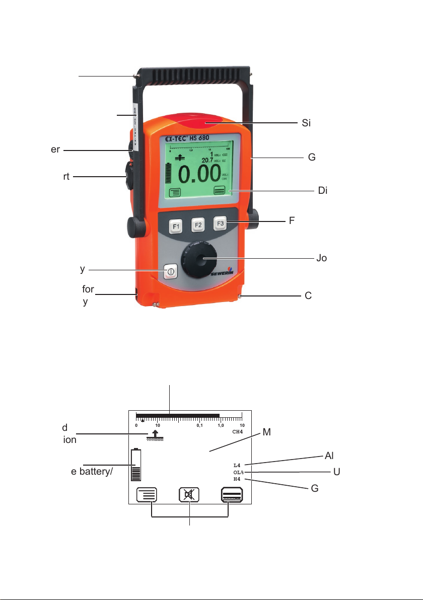
Fig. 1: EX-TEC HS 680 device overview
Bar display
Signal light
Gas input
Display
Function keys
Jog dial
Connector
Selected
application
Capacity
disposable battery/
rechargeable battery
Fig. 2: EX-TEC HS 680 display
Measurement value
Alarm
Unit
Gas type
Current assignment of
function keys F1 – F3
Page 3
Esc
0
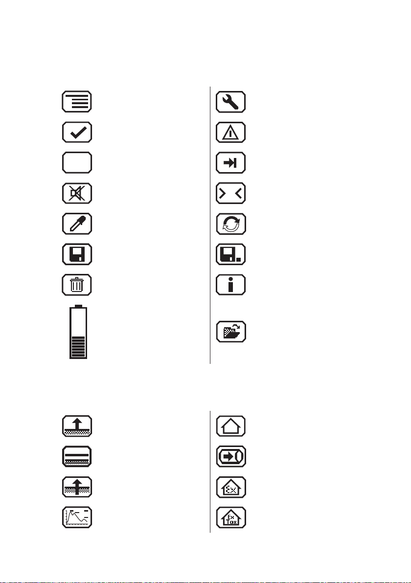
Display symbols
General
Menu Fault
OK Carry out device inspection
Cancel
Buzzer o
Take sample Purge
Save Stop measurement
Delete Information
Capacity disposable battery/rechargeable battery
Applications
Inspection above ground Structure
Tab (jump to next input
eld)
Set zero point
Open stored comment
Open stored inspector
Plants Gas measuring
Measuring in bar holes Warning %LEL
Ethane analysis Warning ExTox
Page 4

Information about this document
The warnings and notes in this document mean the following:
DANGER!
A
A
A
Risk of personal injury. Will result in serious injury or
death.
WARNING!
Risk of personal injury. Can result in serious injury or
death.
CAUTION!
Risk of personal injury. Can result in injury or a risk to
health.
Notice!
Risk of damage to property.
Note:
Tips and important information.
Numbered lists (numbers, letters) are used for:
● Instructions that must be followed in a certain order
Lists with bullet points (point, dash) are used for:
● Lists
● Instructions that only involve one step
Numbers between forward slashes /.../ refer to the referenced documents.
Page 5

Contents Page
1 General .....................................................................................1
1.1 Warranty ....................................................................................1
1.2 Purpose .....................................................................................2
1.3 Intended use .............................................................................3
1.4 General safety information ........................................................4
1.5 Allocation of tasks to applications .............................................5
2 Features ...................................................................................6
2.1 Visual and audible signals .........................................................7
2.2 Sensors .....................................................................................8
2.3 Explosion protection .................................................................. 9
2.3.1 Passive explosion protection ..................................................9
2.3.2 Active explosion protection ..................................................10
3 Operation ............................................................................... 11
3.1 General information on operation ............................................ 11
3.1.1 Keys and jog dial .................................................................. 11
3.1.2 Selecting/exiting menus and menu items .............................12
3.1.3 Switching the device on .......................................................12
3.1.4 Selecting/changing the application .......................................14
3.1.5 Dierences between measuring mode and settings mode ..15
3.2 Measuring mode .....................................................................15
3.2.1 Accessing the menu (measuring mode menu structure) ......16
3.2.2 Zero point ............................................................................. 17
3.2.3 Inspection above ground ...................................................... 18
3.2.4 Plants ...................................................................................19
3.2.5 Measuring in bar holes ......................................................... 20
3.2.6 Ethane analysis ................................................................... 21
3.2.6.1 General information on ethane analysis............................22
3.2.6.2 Purging the detector .......................................................... 24
3.2.6.3 Carrying out an ethane analysis........................................25
3.2.6.4 Evaluating an ethane analysis ..........................................26
3.2.7 Structure ...............................................................................29
3.2.8 Gas measuring ..................................................................... 30
3.2.9 Warning %LEL ....................................................................31
3.2.10 Warning ExTox .....................................................................32
3.2.11 Settings ................................................................................33
3.2.12 Start/stop/save a measurement ...........................................33
3.2.13 Protocols ..............................................................................35
I
Page 6

Contents Page
3.2.14 Device inspection ................................................................. 36
3.2.15 Gas type CxHy ..................................................................... 36
3.2.16 Device information ...............................................................37
3.3 Settings ...................................................................................37
3.3.1 Opening settings ..................................................................37
3.3.2 Settings menu structure .......................................................39
3.3.3 Adjustment ...........................................................................40
3.3.4 System .................................................................................42
3.3.5 Alarms ..................................................................................44
3.3.6 Date/time .............................................................................. 44
3.3.7 Memory ................................................................................44
4 Power supply .........................................................................46
4.1 Suitable disposable/rechargeable battery types .....................46
4.2 Operation with rechargeable batteries ....................................47
4.2.1 Charging ............................................................................... 48
4.2.2 Rechargeable battery maintenance .....................................49
4.3 Battery alarm ........................................................................... 49
4.4 Replacing disposable/rechargeable batteries .........................50
5 Maintenance ..........................................................................51
5.1 Device inspection ....................................................................51
5.1.1 General information on the device inspection ...................... 51
5.1.1.1 Scope ................................................................................ 51
5.1.1.2 Frequency .........................................................................52
5.1.1.3 Documentation .................................................................. 53
5.1.1.4 Integrated device inspection .............................................53
5.1.1.5 Order .................................................................................54
5.1.1.6 Test gases for the device inspection ................................. 54
5.1.2 Performing the device inspection ......................................... 56
5.1.2.1 Accessing the device inspection ....................................... 56
5.1.2.2 Concluding the device inspection......................................57
5.1.3 Testing the general status ....................................................58
5.1.3.1 Housing ............................................................................. 58
5.1.3.2 Signals ..............................................................................59
5.1.3.3 Probe.................................................................................59
5.1.3.4 Filter ..................................................................................59
5.1.3.5 Pump .................................................................................59
5.1.4 Testing indication accuracy with supply of fresh air .............60
5.1.5 Testing indication accuracy with supply of test gas .............. 60
II
Page 7

Contents Page
5.2 Adjustment ..............................................................................62
5.2.1 Scope ...................................................................................62
5.2.2 Test gases for the adjustment ..............................................63
5.2.3 Special features of adjustment with gas mixture .................. 64
5.2.4 Preparation ........................................................................... 65
5.2.5 Performing the adjustment ................................................... 65
5.2.5.1 Adjusting the zero point.....................................................66
5.2.5.2 Adjusting the sensitivity ..................................................... 66
5.2.6 Carrying out an oxygen adjustment .....................................68
5.2.6.1 Adjusting the zero point for oxygen ................................... 68
5.2.6.2 Adjusting the sensitivity for oxygen ................................... 69
5.3 Servicing .................................................................................69
6 Faults ......................................................................................70
7 Appendix ................................................................................71
7.1 Specications and permitted operating conditions .................. 71
7.2 Alarms .....................................................................................72
7.2.1 Features ...............................................................................72
7.2.2 Occupational exposure limits (OEL) and excess factors
(STEL and LTEL) .................................................................. 75
7.2.3 Alarm thresholds (factory settings) .......................................75
7.2.4 Setting ranges for gas types ................................................76
7.3 Limit values for the device inspection .....................................77
7.4 Memory capacity .....................................................................78
7.5 Sensors ...................................................................................79
7.5.1 Infrared sensors (IR) ............................................................79
7.5.1.1 Methane CH4, propane C3H8, butane C4H10 for
Warning %LEL and Warning ExTox ..................................79
7.5.1.2 Methane CH4, propane C3H8 for gas measuring ...............80
7.5.1.3 Carbon dioxide CO2 for warning ExTox ............................. 80
7.5.1.4 Carbon dioxide CO2 for measuring in bar holes ................ 81
7.5.2 Electrochemical sensors (EC) .............................................. 81
7.5.2.1 Oxygen O2 ........................................................................ 81
7.5.2.2 Carbon monoxide CO .......................................................82
7.5.2.3 Hydrogen sulphide H2S ..................................................... 83
7.5.3 Gas-sensitive semiconductor ............................................... 83
7.6 Technical information ..............................................................84
7.6.1 Identication sticker (back of device) ...................................84
7.6.2 Cleaning ............................................................................... 84
III
Page 8

Contents Page
7.6.3 Electrostatic charge ..............................................................84
7.7 Accessories and consumables ................................................ 85
7.8 Declaration of conformity ........................................................86
7.9 Inspection protocols ................................................................87
7.9.1 Test with individual gases .....................................................87
7.9.2 Test with gas mixture ............................................................89
7.10 Advice on disposal ..................................................................91
7.11 Terminology and abbreviations ...............................................92
7.12 Referenced documents ...........................................................93
8 Index .......................................................................................94
IV
Page 9

1 General
1.1 Warranty
The following instructions must be complied with in order for any
warranty to be applicable regarding functionality and safe operation of this equipment. This product must only be commissioned
by qualied professionals who are familiar with the legal requirements (Germany: DVGW).
● Read these operating instructions prior to operating the product.
● Use the product only as intended.
● Repairs and maintenance must only be carried out by special-
ist technicians or other suitably trained personnel. Only spare
parts approved by Hermann Sewerin GmbH may be used when
performing repairs.
● Use only suitable battery types, otherwise the device will not
be explosion-proof.
● Changes or modications to this product may only be carried
out with the approval of Hermann Sewerin GmbH.
● Use only Hermann Sewerin GmbH accessories for the product.
Hermann Sewerin GmbH shall not be liable for damages resulting
from the non-observance of this information. The warranty con-
ditions of the General Terms and Conditions (AGB) of Hermann
Sewerin GmbH are not aected by this information.
In addition to the warnings and other information in these Operating Instructions, always observe the generally applicable safety
and accident prevention regulations.
The manufacturer reserves the right to make technical changes.
1 General
1
Page 10

1 General
1.2 Purpose
The EX-TEC HS 680 and the models 660, 650 and 610 are hand-
held measuring devices which can be used for all gas pipeline
testing applications.
The devices are designed for professional industrial use and
require the necessary specialist knowledge for working in gas
pipelines. Sample applications are described in /3/.
All devices are tted with infrared sensors for measuring hydrocarbons CXHY and carbon dioxide CO2 as standard. Models 680
and 660 also feature a gas-sensitive semiconductor.
Models 680 and 660 can be optionally tted with a detector for
ethane analysis to help you safely distinguish between natural
gas and swamp gas.
All devices can also be individually tted with electrochemical
sensors.
The infrared sensors operate on the principle of absorption via
infrared-active gases, and the electrochemical sensors operate
on the electrochemical cell principle. The gas-sensitive semiconductor reacts to changes in conductivity brought about by
reducible gases.
Note:
These operating instructions describe the EX-TEC HS 680 with
all additional equipment (rmware version 2.XXX). All descriptions refer to the device as delivered (factory settings) and apply
to all device versions. The manufacturer reserves the right to
make changes.
2
Page 11

1.3 Intended use
This device is intended for professional residential and commer-
cial use including small rms and commercial operations. The
appropriate specialist knowledge is required to operate the device.
The device may only be used to measure the following gases
(depending on the device model and additional equipment):
● Methane CH4/propane C3H8/butane C4H
● Carbon dioxide CO
● Oxygen O
● Hydrogen sulphide H2S
● Carbon monoxide CO
The device must not be used for:
● Gas analysis of technical processes
● Monitoring liquids
The device can be used up to a temperature of 40 ºC. However,
high temperatures reduce the lifetime of the sensors and rechargeable batteries.
If a device with an electrochemical sensor is exposed to gas
concentrations above the measuring range limit, this can reduce
the lifetime of the sensor.
1 General
10
2
2
3
Page 12

1 General
1.4 General safety information
● The device has been tested to ensure that it is explosion-proof
in accordance with European standards (CENELEC).
● The device must only be switched on with fresh air.
● Do not use this device in oxygen-enriched atmospheres, oth-
erwise it will not be explosion-proof.
● Only probe hoses with a hydrophobic lter may be used.
Exception:
If the probe has a built-in hydrophobic lter, the hose does not
require any other lters.
● The device must only be tested and adjusted with test gases
in well ventilated rooms or in the open air. Test gases must be
handled in a professional manner.
● Always carry out a device inspection (see section 5.1) after
the device has suered an impact (for example, if dropped
accidentally).
● The device complies with the limits of the EMC directive. Always
observe the information in the manuals of (mobile) radio equipment when using the device close to (mobile) radio equipment.
Note:
Follow the advice regarding explosion protection (see section 2.3).
4
Page 13
1.5 Allocation of tasks to applications
The table is designed to help you decide which application to
choose for which activity (in accordance with /3/).
1 General
Gas measuring
Inspection
above ground
– Ground
– Gas line
e.g. when commissioning/decommissioning gas systems)
– Purging (to demonstrate purity or absence of gas,
– Possible leakage points
Warning %LEL
Warning ExTox
Measuring in
bar holes
– Determining gas dispersion (detection limit)
area monitoring
● Distinguishing between natural gas and swamp gas Ethane analysis
● Warning against explosive gas concentrations through work
monitoring
● Warning against explosive and toxic gases through work area
– Classify leaks
Plants
– Locating a probable gas escape (repair point)
– Preventing possible dangers
● Measuring very low gas concentrations
Structure
● Locating the source of gas
● Finding leaks
● Locating the source of gas
● Finding leaks at internal connections
Location Activity Application
Gas lines, gas systems, … ● Measuring the gas concentration
Buried gas lines ● Measuring very low gas concentrations:
Gas lines, gas systems, …
in houses, enclosed spaces
and shafts
In the ground ● Measuring the gas concentration to:
Poorly accessible gas pipes,
systems
In the house ● Measuring very low gas concentrations
5
Page 14

2 Features
2 Features
The device comes in four models:
EX-TEC HS 680
EX-TEC HS 660
EX-TEC HS 650
EX-TEC HS 610
The models are suitable for the following applications:
Application HS 680 HS 660 HS 650 HS 610
Inspection above ground × ×
Measuring in bar holes
O
2
×
○
×
○
×
○
Plants × ×
Structure
CO
×
○
×
○
Gas measuring × × × ×
Warning %LEL × ×
Warning ExTox
CO
H2S
O
2
×
○
○
○
×
○
○
○
Ethane analysis ○ ○
× standard ○ optional
×
○
6
Page 15

2.1 Visual and audible signals
The device features two alarms:
● Signal light on top of device (visual signal)
● Buzzer on side of device (audible signal)
The signals indicate alarms and faults. The device also emits
signals when it is switched on and o.
If this symbol appears on the display, the audible signal
can be switched o.
When an audible signal has been switched o it cannot
be switched back on while the concentration level remains above the alarm threshold.
This symbol appears at the top left of the display as soon
as the audible signal has been switched o. It disappears
automatically if the level falls below the alarm threshold.
Operating signal
When using the Warning %LEL and Warning ExTox applications,
the device emits a visual and audible signal at regular intervals.
This indicates that the device is working properly.
2 Features
Alarm
The device can monitor several gases at the same time. If the
measured gas concentration of one or more gases exceeds spec-
ied limit values (alarm thresholds) the device gives a warning. It
emits both audible and visual signals, which are clearly dierent
from the operating signal.
WARNING! Risk to life from dangerous gas concen-
A
There is detailed information on alarms in section 7.2.
trations
An alarm always indicates danger.
● Take all necessary measures for your own safety and
the safety of others immediately.
7
Page 16

2 Features
2.2 Sensors
The device features three types of sensor:
● Gas-sensitive semiconductor (SC)
● Infrared sensor (IR)
● Electrochemical sensor (EC)
Application Gas Measuring range Sensors
Inspection above
ground
Plants CH41 ppm – 100 % vol. SC, IR
Measuring in bar
holes
Ethane analysis CH4--- Gas chroma-
Structure CH41 ppm – 100 % vol. SC, IR
CH41 ppm – 10 % vol. SC, IR
CH40.0 – 100 % vol. IR
CO20 – 30 % vol. IR
O
0 – 25 % vol. EC
2
C2H
C3H
6
8
tograph, SC
CO 0 – 500 ppm EC
Gas measuring CH40.0 – 100 % vol. IR
Warning %LEL and
warning ExTox
CH40 – 100% LEL IR
CO 0 – 500 ppm EC
CO20 – 5 % vol. IR
O
0 – 25 % vol. EC
2
H2S 0 – 100 ppm EC
8
Page 17

2.3 Explosion protection
2.3.1 Passive explosion protection
The device is assigned to the following explosion-proof groups:
2 Features
Explosion-proof
group
II2G Ex d e ib IIB T4 Gb – Methane CH
For the following
atmospheres
– Propane C3H
– Butane C4H
4
8
10
– Hydrogen sulphide H2S
When
using
Device
without
carrying
bag TG8
– Carbon monoxide CO
II2G Ex d e ib IIC T4 Gb – Methane CH
– Propane C3H
– Butane C4H
– Hydrogen sulphide H2S
4
8
10
Device
with
carrying
bag TG8
– Carbon monoxide CO
– Hydrogen H
2
EC type-examination certicate: TÜV 07 ATEX 553353 X
DANGER! Risk of explosion from sparks
A
● Only ever open the battery compartment outside of
explosive areas.
● Only ever charge the device outside of explosive areas.
● Only use the USB port outside of explosive areas.
● Use only suitable battery types.
● When working with hydrogen, always use the TG8 car-
rying bag for the device.
9
Page 18

2 Features
2.3.2 Active explosion protection
The functional safety test applies to:
Applications: Warning %LEL
Gas types: Measuring range:
– Methane CH
– Propane C3H
4
8
Gases: Measuring range: As per:
– Oxygen O
– Carbon dioxide CO
2
2
– Carbon monoxide CO 0 – 500 ppm CO /5/
– Hydrogen sulphide H2S 0 – 100 ppm /5/
Tested accessories: – Test set SPE VOL
Warning ExTox
0 – 100% LEL
0 – 100% LEL
0 – 25 % O
0 – 5 % CO
2
2
– Flexible hand probe, 1 m
– Floating probe 2 m / 6 m
/7/
/5/
10
Type examination
Testing institute: DEKRA EXAM GmbH
Certicates: PFG 08 G 002 X
BVS 09 ATEX G 001 X
The following points were not part of the type examination:
● Saving measurement data (see section 3.2.12)
● Saving protocols from the integrated device inspection (see
section 5.1.1.4)
● Disposable alkaline batteries for the power supply (see sec-
tion 4.1)
Page 19

3 Operation
3.1 General information on operation
3.1.1 Keys and jog dial
The ON/OFF key is the only control on the device that does not
change its function.
When switched on, the device is operated using the jog dial and
function keys to navigate the display.
Control Action Function
ON/OFF key Press ● Switches the device on
● Switches the device o
Function keys
F1, F2, F3
Jog dial Turn ● Selects functions, settings,
Press ● Variable
● As indicated on the display at
the bottom of the screen
● Function keys may also have
no function assigned in some
cases
measurement data, etc.
● Modies values
Press ● Opens the next program lev-
el (for example, menu item,
function, measurement data,
selectable values)
● Accepts values
3 Operation
11
Page 20

3 Operation
3.1.2 Selecting/exiting menus and menu items
Functions, applications and settings etc. are selected via the
main menu (for short: Menu). This menu has submenus and
menu items. Refer to section 3.2.1 for information on accessing
the menu.
Selecting submenus/menu items
Submenus and menu items are selected and opened using the
jog dial and/or the function keys.
In measuring mode the name of the selected application is in-
dicated by the symbol at the top left of the display. You can nd
detailed information on selecting and switching applications in
section 3.1.4.
Exiting menus/menu items
There are generally two ways to exit open menus/menu items
and return to the next level up:
● Press Esc
● Select Back from the menu
3.1.3 Switching the device on
Note:
Always switch the device on with fresh air.
1. Press the ON/OFF key. The device switches on.
The switching on process involves an internal check.
Process Test purpose
Buzzer emits audible
signal.
Signal light gives visual
signal.
Display is inverted. Are there pixels missing from the
12
Is the audible signal working?
Is the visual signal working?
display?
Page 21
3 Operation
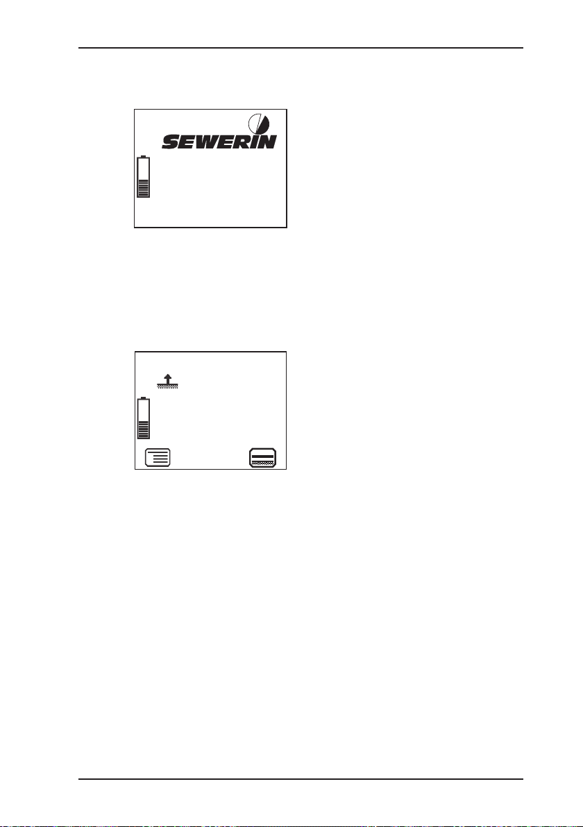
The start screen appears on the display.
Display:
– Device type: EX-TEC HS 680
®
EX-TEC HS 680
– User:
Frank Smith
Frank Smith
City Council
Leakage Delivery
V2.000
Fig. 3: Start screen
17.09.2018
13:02
City Council
Leakage Delivery
– Firmware version: V2.000
– Date and time
– Capacity disposable battery/
rechargeable battery
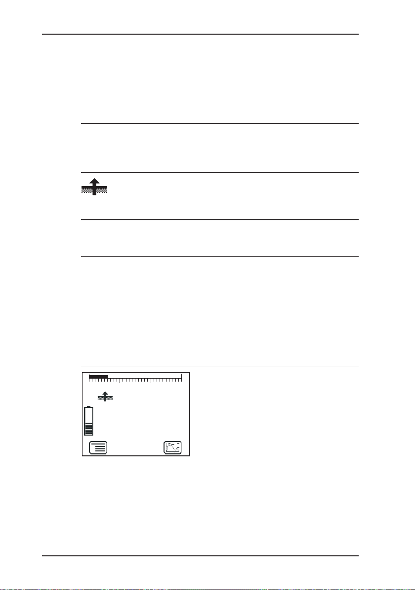
The splash screen for the application set under Autostart
appears (see section 3.3.4).
Display:
CH4
– Gas type: CH
4
– Application as symbol (top left)
Inspection above ground
0 PPM ...10 VOL%
AL 4 3 PPM
and text: Inspection above
ground
– Measuring range:
0 ppm ... 10 % vol.
Fig. 4: Splash screen for
Inspection above
ground application
– Alarm threshold: AL4, 3 ppm
– Symbol for next application that
can be selected via function
key F3: Measuring in bar holes
The device switches to measuring mode. The device warms
up. The reading ashes.
While the device is warming up, the prompt Add fresh air! is
displayed as a reminder.
2. Make sure the device is actually drawing in fresh air. Change
its location if necessary.
3. Wait until the reading stops ashing.
The device is ready for use.
13
Page 22

3 Operation
0
10 100 10
Fig. 5: Inspection above ground measuring mode
WARNING! Risk to life from using miscalibrated or
A
3.1.4 Selecting/changing the application
A
faulty devices
Gas warning devices must be regularly checked before
use.
WARNING! Risk to life from using miscalibrated or
faulty devices
If the device is used as a gas warning instrument (Warning %LEL and Warning ExTox applications), it must be
regularly checked before use.
0,1
1,0
PPM
CH4
0
● Carry out a device inspection each day before starting
work.
● Carry out a device inspection each day before starting
work.
Display:
– Current reading: zero when
device is switched on with fresh
air
14
Note:
You may only switch applications when the device is drawing in
fresh air.
The current application is indicated by the symbol at the top left
of the display. The symbol at the bottom right shows the next application that can be selected via function key F3. You can specify
Page 23

3 Operation
which application is activated rst when the device is switched on
in the Settings under System (see section 3.3.4).
● Press Menu. Select the menu item for the application you
want to use.
OR
a) Press function key F3. The device switches to the next ap-
plication.
b) Repeat until the symbol for the application you want to use
appears at the top left.
3.1.5 Dierences between measuring mode and settings mode
The device is operated in two modes:
● Measuring mode (see section 3.2)
Measurements are taken in measuring mode. All functions
needed to take readings can be accessed from one menu.
● Settings (see section 3.3)
The device settings can be changed in settings mode. Information about the device can also be retrieved. Measurements
cannot be taken in settings mode.
Settings are accessed via the menu in measuring mode. The
settings are access-protected by a PIN code.
WARNING!
A
3.2 Measuring mode
When switched on the device is in measuring mode. In meas-
uring mode, the current readings are always displayed (g. 5).
Risk to life due to absence of alarm
The device only issues alarms in measuring mode. As
soon you open the menu, alarms are no longer triggered.
● Only adjust settings in areas where there is no risk of
explosion and where there is no toxic or low-oxygen
atmosphere.
15
Page 24

3 Operation
Zero point
Exit
3.2.1 Accessing the menu (measuring mode menu structure)
Depending on the application, the measurement will have to be
saved or started and then stopped (see section 3.2.12).
WARNING!
A
Risk to life from operating signal failure
When the device is used as a gas warning device (Warning %LEL and Warning ExTox applications), an operat-
ing signal must always sound in measuring mode. If the
operating signal does not sound, the device is not safe
to operate.
● Stop using the device immediately.
● Leave explosive areas or areas with a toxic or low-ox-
ygen atmosphere immediately.
In measuring mode F1 can be used to access the Menu.
Inspection above ground
Plants
Measuring in bar holes
Ethane analysis
Structure
Gas measuring
Warning %LEL
Warning ExTox
Settings
Start measurement
Protocol
Purge
Device inspection
Gas type CxHy
Device information
Fig. 6: Menu with submenus (menu items)
16
Page 25

Once you have started a measurement Start measurement in
the menu becomes Stop measurement. In some applications
this menu item is called Save measurement.
You can nd detailed information on starting, stopping and saving
measurements in section 3.2.12.
Protocol does not appear in the menu until you save a protocol
for the rst time.
Purging only appears in the menu in the ethane analysis application.
Gas type CxHy only appears in the menu if the device is equipped
for at least one further gas type apart from methane CH4.
3.2.2 Zero point
The zero point can be manually set under Zero point in the menu.
This is only necessary if the displayed fresh air measurement is
not zero after the end of the warm-up period.
Gas Content in fresh air Correct zero point on device
CH4 0 % vol. 0.0 % vol.
CO 0 ppm 0 ppm
CO20.04 % vol. 0.04 % vol.
O2 20.9 % vol. 20.9 % vol.
3 Operation
The manual zero point setting is not saved. The zero point can be
corrected by adjustment as often as zero point deviations occur
(see section 5.2).
Requirements for correct setting of the zero point
● Device has been switched on with fresh air.
● Device continues to draw in fresh air.
Setting zero point (manual zero point setting)
1. Press Menu.
2. Select Zero point menu item. The values are automatically
adjusted. The device returns to measuring mode.
17
Page 26

3 Operation
The Setting zero point function can also be accessed using the
relevant symbol in the Inspection above ground, Plants and
Structure applications.
3.2.3 Inspection above ground
The measuring mode can be changed for the Inspection above
ground application via this menu item.
Area of use
– Measuring minimal gas concentrations above the ground, the
gas pipe or possible leakage points
Symbol
Unit
– ppm (parts per million)
– % vol.
Measuring range
18
Gas-sensitive semiconductor 0 to 10,000 ppm
Infrared sensor 1 to 10 % vol.
Measurement data display
0
10 100 10
0,1
1,0
– Digit, for example,
0.90 % vol. CH
– Bar graph with quasi-loga-
AL4
0.90
Fig. 7: Inspection above ground measuring mode
VOL%
CH4
rithmic scale
4
Page 27

3.2.4 Plants
The measuring mode can be changed for the Plants application
via this menu item.
Area of use
– Measuring minimal gas concentrations in freely accessible
gas pipes and systems (e.g. gas pipes on bridges, above-
ground inverted siphons, biogas plants)
– Locating the source of gas
– Finding leaks
Symbol
Unit
– ppm (parts per million)
– % vol.
Measuring range
3 Operation
Gas-sensitive semiconductor 0 to 10,000 ppm
Infrared sensor 0.1 to 100 % vol.
Measurement data display
0,1
100
0
10
10
1,0
100
– Digit, for example,
8 ppm CH
4
– Bar graph with quasi-loga-
rithmic scale
PPM
8
CH4
Fig. 8: Plants measuring mode
19
Page 28
3 Operation
3.2.5 Measuring in bar holes
The measuring mode can be changed for the Measuring in bar
holes application via this menu item.
Area of use
– Measuring gas dispersal in the ground
– Locating the possible leakage point and classifying the leak
Symbol
Unit
– % vol.
Measuring range
Infrared sensor
0.0 to 100 % vol.
(hydrocarbons CXHY)
Infrared sensor
0.0 to 30 % vol.
(carbon dioxide CO2)
Electrochemical sensor
0.0 to 25.0 % vol.
(oxygen O2)
Measurement data display
– Digit, for example,
1,0
0
20.9
10
0
VOL% CO2
VOL% O2
100
0 % vol. CO
20.9 % vol. O2
0.60 % vol. CH
0.60
Fig. 9: Measuring in bar holes measuring mode
VOL%
CH4
– Bar display with quasi-logarith-
mic scale (for CH4)
2
4
20
Page 29

3.2.6 Ethane analysis
Selecting Ethane analysis from the menu opens an overview of
the gases that can be detected. The device automatically returns
to measuring mode.
Note:
The ethane analysis cannot be started with the Ethane analysis
menu item.
Information about carrying out the ethane analysis can be found
in section 3.2.6.3.
Area of use
– Distinguishing between natural gas and swamp gas
Symbol
Unit
3 Operation
– ppm (parts per million)
– % vol.
Measuring range
Infrared sensor
(hydrocarbons CXHY)
Infrared sensor
(carbon dioxide CO2)
Electrochemical sensor
(oxygen O2)
Gas chromatograph /
gas-sensitive semiconductor
0.0 to 100 % vol.
0 to 30 % vol.
0.0 to 25.0 % vol.
1 ppm to 1.2 % vol.
21
Page 30

3 Operation
Measurement data display
0,1
0
100
10
1,0
20.9
10
VOL% CO2
0
VOL% O2
100
0 % vol. CO2
20.9 % vol. O2
9.0 % vol. CxH
– Digit, for example,
9.0
Fig. 10: Ethane analysis measuring mode
VOL%
CxHy
– Bar display with quasi-logarith-
mic scale (for CxHy)
3.2.6.1 General information on ethane analysis
Ethane analysis is used to demonstrate the presence of natural
gas and to distinguish between natural gas and swamp gas.
This analysis utilises the fact that natural gas contains ethane,
but swamp gas does not. Thus, if ethane is detected, it can be
concluded that natural gas is present.
Note:
Ask the network operator about the composition of natural gas.
Request an analysis certicate.
Ethane can denitely be detected in natural gas at a minimum
concentration of 1 % vol. If the concentration of ethane in natural
gas is less than 0.5 % vol., the gas cannot be detected. If the
concentration falls between these two values, the analysis can
be carried out, but the result must be assessed subsequently.
During the ethane analysis, the gas sample is always analysed
for the presence of the following three gases:
● Methane CH
● Ethane C2H
● Propane C3H
4
6
8
Y
22
Requirement
The ethane analysis only works if the gas sample exhibits a spe-
cic concentration.
Page 31

3 Operation
The device checks the concentration at the start of the analysis
and prevents the analysis being carried out if the concentration
is too low.
Gas sample
concentration
> 1 % vol. Denitely
Analysis
is …
Device response
Analysis can be carried out
possible
1 % vol. – 0.5 % vol. Technical-
ly possible
< 0.5 % vol. Not pos-
sible
Analysis can be carried out,
but Ethane analysis critical
note appears
Analysis cannot be carried
out because Take sample
symbol is not displayed
Displayed measurement values
In measuring mode, the device displays the actual concentra-
tions (g. 9).
During the analysis, the device automatically dilutes the gas
sample to 1 % vol. to ensure optimal utilisation of the semiconductor sensor. This means:
● The concentration ratios of all components of the gas sample
are retained.
● The maximum concentration of a gas component is 1 % vol.,
even if the actual concentration in the gas sample is higher.
In the mode of curve, the maximum peak may be cut o as
necessary (g. 12 right).
Number of measurements
Always carry out 2–3 measurements in the same location to
obtain certain results. Observe the information on evaluation in
section 3.2.6.4.
23
Page 32

3 Operation
3.2.6.2 Purging the detector
The detector for ethane analysis must be kept clean at all times
to prevent distortion of measurement results. When the device
is in use, however, higher hydrocarbons (e.g. propane, butane)
can accumulate in the detector and contaminate it.
The detector is automatically purged after every ethane analysis.
Additional purging of the detector is required in these situations:
● Cancelled ethane analysis
If an ethane analysis is cancelled, the message Purging re-
quired and the Take sample symbol appear automatically.
● Detector contamination suspected
Note:
The purge always takes 4 minutes. A new ethane analysis can
only be started when the purge cycle has been completed.
The device is in measuring mode.
1. Only when detector contamination is suspected:
a) Press Menu.
b) Select the Purging menu item. The message Purging re-
quired and the Take sample symbol appear.
24
NOTICE! Risk of damaging the sensor
A
2. Make sure the device is drawing in fresh air.
3. Press Take sample.
After the purge cycle is complete, the device will revert to measuring mode.
The ethane detector will be damaged if the air supply is
contaminated or moist
● Always add clean, dry fresh air.
The purge cycle starts automatically as soon as the gas concentration drops below 50 ppm. The time remaining until the
end of the purge cycle is displayed.
Page 33

3.2.6.3 Carrying out an ethane analysis
The device is in measuring mode.
1. Make sure the device is drawing in fresh air.
2. Change to the Ethane analysis application.
3. The ethane analysis is generally performed on a bar hole. Use
the localisation probe and a probe hose.
a) Insert the probe into the bar hole.
b) Connect the probe hose to the device.
As soon as the measurement value satises specic conditions
(gas concentration >1 % vol., stable measurement value), the
Take sample symbol appears.
4. Press Take sample. A message appears.
Note:
An ethane analysis takes approximately 4 minutes. After Esc is
used to cancel the analysis, the detector must be purged (see
section 3.2.6.2). This purge cycle also takes 4 minutes.
3 Operation
5. Conrm the Take sample? prompt by pressing OK. The gas
sample is taken.
The Add fresh air note appears.
6. Add fresh air.
a) To do so, remove the probe hose from the device.
b) Move away from the bar hole. Note the direction of the wind.
As soon as the gas concentration drops below 50 ppm, the
analysis of the gas sample taken starts automatically. The gas
sample analysis is plotted on the display.
25
Page 34

3 Operation
150 200050 100
C3H8
Analysis
Yes
CH4
Yes
C2H6
Yes
C3H8
250 s
1,0
CH4
C2H6
0,1
100
10
088 Seconds
Fig. 11: Mode of curve of an analysis in progress
When the analysis is complete, the Save symbol appears.
7. Press Save.
8. If necessary enter a Comment on the analysis.
a) Select the characters required using the jog dial. Conrm
each character using the jog dial.
OR
− Press Open stored comments. A list of the stored com-
ments will appear.
− Select the desired comment. Open the comment with OK.
b) Then conrm your entry/selection with OK.
OR
Press Esc if you do not wish to enter a comment.
9. Conrm your entry with OK. The comment is saved together
with the protocol name (date, time).
3.2.6.4 Evaluating an ethane analysis
Fully completed ethane analyses are saved as protocols. These
can be accessed and cleared at any time.
26
Page 35

3 Operation
CH4
1,0
0,1
100
10
17.09.2018
11:21 12/47
Analysis
CH4
C2H6 ????
C3H8 ----
150 200050 100
Fig. 12: Ethane analysis
protocol
250 s
A protocol contains the following
Yes
information about the gas sample:
– Analysis of the gas components:
CH4 Yes
C2H6 ????
C3H8 – – – –
– Curve; peaks of the gas compo-
nents denitely present in the
sample are labelled: CH
4
– Date and time the protocol was
saved
– Protocol number: 12/47, i.e.
12th protocol of 47 protocols in
total
The symbols next to the analysed gas components are dened
as follows:
Symbol Gas component is …
Yes Denitely present
???? Possibly present
– – – – Not present
Ideally, the result of the ethane analysis is a curve with at least
one clear, steep peak (g. 12 left). However, occasionally, the
analysis does not provide a clear determination of the gas com-
ponents present (g. 12 right). In such cases, you must decide
whether the analysis quality is sucient.
CH4
1,0
C2H6
0,1
100
10
17.09.2018
11:35 13/47
C3H8
150 200050 100
Analysis
Yes
CH4
C2H6 Yes
C3H8 Yes
250 s
Fig. 13: Quality assessment of an ethane analysis; Left: good quality,
Right: poor quality
CH4
1,0
0,1
100
10
17.09.2018
11:57 14/47
Analysis
Yes
CH4
C2H6 ????
C3H8 ----
150 200050 100
250 s
27
Page 36

3 Operation
Criteria for determining good analysis quality
Criteria for determining the presence of natural gas
Ethane analyses of insucient quality
Note:
Never use poor-quality ethane analyses to demonstrate the presence of natural gas.
Poor-quality ethane analyses can exhibit the following features, for
example:
● Methane is denitely present.
● Methane concentration is 1 % vol.
● Peaks of the gas components present are clearly recognisable.
● Good analysis quality (see above)
● Ethane is denitely present.
● Curve does not contain any clear peaks (smooth concentra-
tion plot)
28
Reason: Residual gases from previous analyses have
accumulated.
Corrective
action:
Purge with test gas, for example:
– 1 % vol. CH4 in synthetic air
OR
– 100 ppm C2H6 with 1 % vol. CH4 in synthetic air
● Curve and symbols (Analysis) provide contradictory informa-
tion about gas components
Reason: Extremely high or low temperatures (optimal
working temperature: 20°C)
Page 37

3.2.7 Structure
The measuring mode can be changed for the Structure application via this menu item.
Area of use
– Measuring minimal gas concentrations in structures.
– Locating the source of gas
Symbol
Unit
– ppm (parts per million)
– % vol.
Measuring range
Gas-sensitive semiconductor 0 to 10,000 ppm
Infrared sensor 0.1 to 100 % vol.
3 Operation
Electrochemical sensor
(carbon monoxide CO)
Measurement data display
0,1
100
0
10
Fig. 14: Structure measuring mode
1,0
0
4
10
PPM CO
PPM
CH4
100
0 to 500 ppm
– Digit, for example,
0 ppm CO 4 ppm CH
4
– Bar display with quasi-loga-
rithmic scale (for CH4)
29
Page 38

3 Operation
3.2.8 Gas measuring
The measuring mode can be changed for the Gas measuring
application via this menu item.
WARNING!
A
Area of use
Symbol
Risk to life due to absence of alarm
The device does not sound an alarm in the gas measuring application.
● Before switching application, please make sure there
are no ignition sources close by.
● Do not smoke.
● Be extremely careful.
– Demonstrating gas purity / absence of gas in gas pipes
30
Unit
– % vol.
Measuring range
Infrared sensor 0 to 100 % vol.
Measurement data display
1,0
0
30
Fig. 15: Gas measuring mode
100
10
VOL%
CH4
– Digit, for example,
30 % vol. CH
– Bar graph with quasi-logarith-
mic scale
4
Page 39

3.2.9 Warning %LEL
The measuring mode can be changed for the Warning %LEL
application via this menu item.
WARNING!
A
Risk to life from operating signal failure
If the operating signal does not sound, the device is not
safe to operate.
● Stop using the device immediately.
● Leave explosive areas or areas with a toxic or low-ox-
ygen atmosphere immediately.
Area of use
– Testing work environments where explosion is possible, e.g.
when working on gas pipes or gas systems
Symbol
3 Operation
Unit
– % LEL or % vol.
Measuring range (methane CH4)
Infrared sensor 0 to 100 % LEL or
0.00 to 4.40 % vol.
Measurement data display
010
50
30
40
70
80
20
60
90 100
– Digit, for example,
14 % LEL CH
4
– Bar display with linear scale,
alarm thresholds marked AL1
AL1
%LEL
14
Fig. 16: Warning %LEL measuring mode
CH4
and AL2
31
Page 40

3 Operation
3.2.10 Warning ExTox
The measuring mode can be changed for the Warning ExTox
application via this menu item.
WARNING!
A
Risk to life from operating signal failure
If the operating signal does not sound, the device is not
safe to operate.
● Stop using the device immediately.
● Leave explosive areas or areas with a toxic or low-ox-
ygen atmosphere immediately.
Area of use
– Warning of explosive and toxic gas concentrations as well as
lack of oxygen
Symbol
32
Unit
– % LEL (methane CH4)
– % vol. (carbon dioxide CO2, oxygen O2)
– ppm (carbon monoxide CO, hydrogen sulphide H2S)
Measuring range (methane CH4)
Infrared sensor 0 to 100 % LEL
Measurement data display
AL1 CH4
CO2
AL1 O2
AL1 CO
AL1 H2S
Fig. 17: Warning ExTox measuring mode
34
0.17
11.5
34
34
%LEL
VOL%
VOL%
PPM
PPM
– Digit, for example,
34 % LEL CH
0.17 % vol. CO
11.5 % vol. O
4
2
2
34 ppm CO
34 ppm H2S
Page 41

CAUTION!
A
3.2.11 Settings
You can change the device settings and access information about
the device under Settings in the menu (see section 3.3).
3.2.12 Start/stop/save a measurement
Depending on the application, measurements will have to be
saved or started and then stopped. The ethane analysis is an
exception (see section 3.2.6.3).
Health risk due to late alarm
If you change the device from the Warning ExTox appli-
cation to another application, data that could initiate an
STEL or LTEL alarm is reset to zero.
● Only switch from Warning ExTox to another application
once you have left the work area being monitored.
3 Operation
Application
Inspection above ground ×
Plants ×
Measuring in bar holes ×
Structure ×
Gas measuring ×
Warning %LEL ×
Warning ExTox ×
Dierence between starting/stopping and saving
Selecting Start measurement followed by Stop measurement
saves a measurement plot.
Selecting Save measurement saves an individual measurement,
the current one.
start/stop save
Measurement
33
Page 42

3 Operation
Note:
Measurements cannot be cancelled. The only way to cancel a
measurement is to stop it.
Up to 80 measurements can be saved.
The measurement values can be saved with or without a comment. Comment entries are saved automatically (ring memory
with max. 10 entries).
The stored measurements can be displayed on a computer using
a readout program. The program is available at www.sewerin.
com.
Starting a measurement
1. Press Menu.
2. Select Start measurement from the menu. This starts the
The measurement plot recording must always be concluded with
Stop measurement.
Once the rst comment has been entered, the Open
stored comments function will become available.
measurement plot recording.
34
Stopping a measurement
1. Press Stop measurement.
OR
a) Press Menu.
b) Select Stop measurement from the menu.
2. Answer Yes to the warning prompt.
3. Enter a comment for the measurement.
a) Select the characters required using the jog dial. Conrm
each character using the jog dial.
OR
− Press Open stored comments. A list of the stored com-
ments will appear.
− Select the desired comment. Open the comment with OK.
Page 43

3 Operation
b) Then conrm your entry/selection with OK.
OR
Press Esc if you do not wish to enter a comment for the
measurement.
The measurement is saved as a protocol. The protocol name
is formed from the date, time and comment.
Saving a measurement
1. Press Menu.
2. Select Save measurement from the menu.
3. Enter a comment for the measurement.
a) Select the characters required using the jog dial. Conrm
each character using the jog dial.
OR
− Press Open stored comments. A list of the stored com-
ments will appear.
− Select the desired comment. Open the comment with OK.
b) Then conrm your entry/selection with OK.
OR
Press Esc if you do not wish to enter a comment for the
measurement.
The measurement is saved as a protocol. The protocol name
is formed from the date, time and comment.
3.2.13 Protocols
You can retrieve or clear protocols of saved data under Protocol
in the menu. When saved, the protocols are assigned to dierent
protocol types.
The following protocol types are available:
● Ethane analysis
● Device inspection
● Measurements
Protocols can only be cleared individually.
35
Page 44

3 Operation
You can nd information on how to clear all protocols of one protocol type in section 3.3.7.
3.2.14 Device inspection
The device inspection can be used to check the general status
and the indication accuracies. Device inspection only appears
in the menu when the integrated device inspection is switched on.
Note:
The integrated device inspection is switched o in the factory
settings. More detailed information about the device inspection
can be found in section 5.1.
The frequency of the device inspection depends on the application (see section 5.1.1.2).
If the integrated device inspection is switched on, the device will
remind you to perform a device inspection.
The Device inspection symbol will appear when the
inspection is due. It is visible in the display until the
complete integrated device inspection has been carried
out successfully.
3.2.15 Gas type CxHy
You can temporarily change the gas type under the Gas
type CxHy menu item, provided the device is designed for other
gas types. Gas types available for selection:
● Methane CH
● Propane C3H
● Butane C4H
10
The temporary gas type change is not saved. If you need to set
a dierent default gas type, you can do this in the Settings menu
item under System.
36
4
8
Page 45

3.2.16 Device information
The following device information is shown under Device information in the menu:
● Installed electrochemical sensors: gas, installation date, war-
ranted/expected lifetime
● Firmware: version, date
● Service: date of the last service, date of the next service
3.3 Settings
The following menus and menu items are included under Settings:
● Adjustment
● System
● Alarms
● Date/time
● Memory
You can nd information on selecting and exiting menus and
menu items in section 3.1.2
3 Operation
3.3.1 Opening settings
1. Press Menu.
WARNING!
A
2. Select Settings from the menu.
Risk to life due to absence of alarm
The device only issues alarms in measuring mode. As
soon you open the menu, alarms are no longer triggered.
● Only adjust settings in areas where there is no risk of
explosion and where there is no toxic or low-oxygen
atmosphere.
Access is protected by a PIN code. The default setting is
always PIN code 0001.
37
Page 46

3 Operation
Adjustment
Exit
Note:
You can change the PIN code at any time.
SEWERIN recommends setting a dierent PIN code after initial
start-up so that only authorised personnel have access to the
settings.
3. Enter the PIN code from left to right. The active digit is always
displayed with a black background.
Digit To change To conrm
1st digit
Press the jog dial
2nd digit Press the jog dial
3rd digit Press the jog dial
Turn the jog dial
4th digit
If the PIN code has been entered correctly, the Settings menu
will appear once the last digit has been conrmed (g. 18).
Otherwise the device will revert to measuring mode.
38
System
Alarms
Date/time
Memory
Fig. 18: Settings menu
Page 47

3.3.2 Settings menu structure
Measuring mode
3 Operation
Settings Adjustment Adjustment CH4 PPM
PIN Code
System PIN Code
Alarms
Date/time
Memory Clear
Exit
Adjustment CH4
Adjustment CO2
Adjustment O2
Adjustment CO
Adjustment H2S
Adjustment gas mixture warning
Adjustment gas mixture gas measuring
Test gas
Inspection OK
Exit
Service interval
Display
Battery
Autostart
Gas type CxHy
Unit %LEL
PPM multiplicator
Device inspection
Reset
Language
Exit
Interval
Memory mode
Exit
Fig. 19: Settings menu structure for EX-TEC HS 680 (gas type: meth-
ane)
Note:
The number and names of available menu items depend on the
device model and optional additional equipment.
39
Page 48

3 Operation
3.3.3 Adjustment
The Adjustment menu is used to set the sensors.
WARNING! Danger of death due to incorrect adjust-
A
A detailed description of adjustment along with important information is provided in section 5.2.
Adjustment CxHy ppm
Used to adjust the gas-sensitive semiconductor for gas type CxHy
(methane CH4, propane C3H8, butane C4H10) in the ppm range.
Applications: – Inspection above ground
ment
Incorrect adjustment can lead to incorrect measurement
results. This means that the user may not be warned about
dangerous gas concentrations in time.
● Only specialist technicians may perform adjustments.
● Adjustments must be made in well ventilated rooms or
in the open air.
– Ethane analysis
– Plants
– Structure
40
Adjustment CxHy
Used to adjust the infra red sensor for gas type CxHy (methane
CH4, propane C3H8, butane C4H10) in the % vol. range / LEL range.
Applications: – Inspection above ground
– Measuring in bar holes
– Ethane analysis
– Plants
– Structure
– Gas measuring
– Warning %LEL
– Warning ExTox
Page 49

3 Operation
Adjustment CO2
Used to adjust the infrared sensor for carbon dioxide CO2 in the
% vol. range.
Applications: – Measuring in bar holes
– Ethane analysis
– Warning ExTox
Adjustment O2
Used to adjust the electrochemical sensor for oxygen O2 in the
% vol. range.
Applications: – Measuring in bar holes
– Ethane analysis
– Warning ExTox
Adjustment H2S
Used to adjust the electrochemical sensor for hydrogen sulphide
H2S in the ppm range.
Application: – Warning ExTox
Adjustment CO
Used to adjust the electrochemical sensor for carbon monoxide CO in the ppm range.
Application: – Warning ExTox
Adjustment gas mixture warning
Used to adjust the infrared and electrochemical sensors for all
components of the test gas (gas mixture).
Applications: – Warning %LEL
– Warning ExTox
Adjustment gas mixture gas measuring
Used to adjust the infrared sensors for methane CH4 and carbon
dioxide CO2.
41
Page 50

3 Operation
Applications: – Measuring in bar holes
Test gas concentration
Used to adjust the concentration of the test gases used.
Inspection OK
Conrms the device is in proper working order. This extends the
service interval.
3.3.4 System
General information and specications for operation are set in
the System menu.
PIN code
Used to change or reset the PIN code.
Note:
If you lose the PIN code, you must contact SEWERIN Service.
If the PIN code is set to 0000, you will not be asked to enter it.
The settings can then be accessed by anyone.
– Ethane analysis
– Gas measuring
42
Service interval
Species the regular inspections/maintenance required for the
device. You can also activate the automatic switch-o function
once the set interval has passed.
Display
Used to set how long the display remains illuminated after any
key is pressed as well as the display contrast.
Page 51

3 Operation
Battery
Used to set the type of disposable/rechargeable battery used.
NOTICE! Damage possible due to device overheating
If the battery type is not correctly set, the device can overheat.
● Always enter the correct battery type.
Autostart
Sets the application that is automatically activated when the device is switched on.
Gas type CxHy
Sets the gas type (methane CH4, propane C3H8, butane C4H10)
which is automatically used when the device is switched on.
Unit %LEL
Used to set the unit of measurement. Only applies to Warning
%LEL and Warning ExTox applications.
PPM multiplicator
Set the amplication factor for the lower ppm range.
Measurement x factor = displayed measurement
Application: – Inspection above ground
Device inspection
Used to switch the integrated device inspection on or o.
Factory settings
Used to reset the device settings to the factory settings.
Language
Sets the language.
43
Page 52

3 Operation
3.3.5 Alarms
Sets the alarm thresholds for the gas types and gases.
Alarm AL3 cannot be set. It always occurs at the end of the
measuring range.
There is detailed information on alarms in section 7.2.
AL1 alarm
Used to set the pre-alarm.
Applications: – Plants
AL2 alarm
Used to set the main alarm.
Applications: – Plants
– Structure
– Warning %LEL
– Warning ExTox
– Structure
– Warning %LEL
– Warning ExTox
AL4 alarm
Used to set the alarm threshold in excess of signicant gas concentrations which indicate a gas leak.
Application: – Inspection above ground
3.3.6 Date/time
Used to set the time, day, month and year. There are two formats
available for the date.
3.3.7 Memory
The Memory menu is used to specify how measurement data
and protocols are handled.
44
Page 53

3 Operation
Clear
Used to clear protocols.
The dierent protocol types must each be cleared separately. All
protocols in one protocol type are cleared at once.
You can nd information on clearing individual protocols in sec-
tion 3.2.13.
Interval
Sets the interval at which measurement data is automatically
saved.
Memory mode
Switches between ring memory and stack memory.
45
Page 54

4 Power supply
4 Power supply
This device can be operated using:
● Disposable (non-rechargeable) alkaline batteries
● Rechargeable NiMH batteries
The device comes with nickel metal hydride rechargeable batteries. The corresponding settings are stored.
WARNING! Risk of explosion from leaking batteries
A
4.1 Suitable disposable/rechargeable battery types
Leaking electrolyte can reduce the creepage distance
and air gaps between the poles. This may mean that the
batteries no longer meet the required standards.
● Replace leaking batteries immediately.
● Clean the battery compartment (and, if necessary, the
device) before inserting the new disposable/rechargeable batteries.
46
A
WARNING! Risk of explosion due to unsuitable batteries
To ensure that the device remains explosion-proof in accordance with /16/, only certain disposable/rechargeable
batteries may be used.
● Only use batteries supplied by SEWERIN. Other dis-
posable/rechargeable batteries, which have not been
supplied by SEWERIN, may only be used if they meet
the requirements of /8/.
● In each battery compartment use only batteries that are
identical with respect to type (disposable or recharge-
able), capacity and manufacturer.
Page 55

4 Power supply
Disposable battery requirements
● Disposable alkaline batteries
● Size: AA, type: LR6 as per /11/
● The creepage distance and air gap between the poles must
not be less than 0.5 mm in accordance with /8/.
Rechargeable battery requirements
● NiMH rechargeable batteries
● Size: AA, type: HR6 as per /13//
● The creepage distance and air gap between the poles must
not be less than 0.5 mm in accordance with /8/.
● The rechargeable batteries must be fast charging (I > 1.25 A)
and remain within the temperature range.
Note:
A device operated with disposable alkaline batteries cannot be
charged. A note to this eect is shown on the display.
4.2 Operation with rechargeable batteries
The operating time of the device depends on the battery capacity.
If the device is not used or not kept in the docking station, the
batteries will lose their charge due to self-discharge. The self-discharge intensity depends on the battery type.
47
Page 56

4 Power supply
4.2.1 Charging
The device can be charged via:
● Connection for power supply
● Docking station TG8
DANGER! Risk of explosion from sparks
A
For charging you will need either:
Please note the following points:
High charging amperage occurs when charging batteries
in explosive areas.
The mains adapter is not explosion proof.
● AC/DC adapter M4
● Vehicle cable M4
● The device or docking station must not be directly connected
to a 24-V on-board power supply in the vehicle. The voltage is
too high for the charging process.
● The battery should be charged at approximately room tem-
perature.
● Several TG8 docking stations must not be connected in series
(cascaded).
● Only ever charge the device outside of explosive areas.
48
Page 57

4.2.2 Rechargeable battery maintenance
If the device is not used for a long period of time, it is advisable
to fully discharge the battery before recharging it again.
A full discharging and recharging process takes approx. 11 hours
(8 hours to discharge + 3 hours to recharge). The duration depends on the capacity of the rechargeable batteries used.
DANGER! Risk of explosion from sparks
A
High charging amperage occurs when charging batteries
in explosive areas.
The mains adapter is not explosion proof.
● Only ever charge the device outside of explosive areas.
● Connect the device (switched on) to the power supply via the
side connection
OR
Place the device (switched on) into the docking station.
The rechargeable batteries will be fully discharged. Once the
device has been discharged, it will automatically switch to
charging mode.
4 Power supply
4.3 Battery alarm
As soon as the remaining capacity of the batteries gets low, a
battery alarm will go o:
Level 1: Battery almost empty
Level 2: Battery empty
– Battery capacity symbol ashes
– Audible signal (one-o)
– Operating signal doubles
– Remaining operating time: approx. 15 min
– Blank display apart from Battery capacity sym-
bol
– Continuous audible signal
– Measuring mode unavailable
– Device shuts o
49
Page 58

4 Power supply
4.4 Replacing disposable/rechargeable batteries
DANGER! Risk of explosion from sparks
A
A 2.5 mm Allen key (supplied) is required to open the battery
compartment on the back of the device.
1. Loosen the two screws securing the battery compartment. Re-
2. Lift out the battery compartment.
3. Remove the disposable/rechargeable batteries and insert new
4. Replace the battery compartment so it ts neatly into place
5. When you switch the device back on again, you will be asked
If it takes longer than 120 seconds to replace the batteries, the
date and time will have to be reset the next time you switch the
device on. All the other data will be saved.
The device is not explosion proof when the housing is
open.
● Only ever open the battery compartment outside of
explosive areas.
move the screws by repeatedly turning them alternately a short
way; this ensures that the battery compartment does not twist.
ones. Ensure that the batteries are inserted with the correct
polarity.
and secure rmly with the screws.
which battery type is in use. Enter the correct battery type.
50
Page 59

5 Maintenance
In accordance with the legal regulations, device maintenance
comprises the following elements:
● Device inspection including test of indication accuracy
● Adjustment
● Servicing
All inspections must be documented. The documentation must
be retained for at least one year.
WARNING! Risk to life from using miscalibrated or
A
faulty devices
If the device is used as a gas warning instrument (Warning %LEL and Warning ExTox applications), it must be
regularly checked before use.
● Carry out a device inspection each day before starting
work (as per /1/, /2/, /6/, /10/).
5 Maintenance
5.1 Device inspection
5.1.1 General information on the device inspection
5.1.1.1 Scope
The device inspection includes the following tests:
● Analysis of the general status
● Test of the indication accuracy with supply of fresh air
● Test of the indication accuracy with supply of test gas
51
Page 60

5 Maintenance
5.1.1.2 Frequency
The frequency of the device inspection depends on the application.
Application When to test Legal basis
Inspection above
ground
Plants Weekly to every six
Measuring in bar
holes
Structure
Gas measuring
Warning %LEL Every day before starting
Warning ExTox /1/, /2/, /6/, /10/
Ethane analysis Quarterly
If the integrated device inspection is switched on, the device will
remind you to perform a device inspection.
The applications are grouped together for the device inspection.
The device inspection must be performed separately for each
group.
Before starting work and
if out of use for long periods
months
work
/3/
/3/
/2/, /10/
52
Devices with multiple gas types
For devices that are designed for multiple gas types, the device
inspection must be carried out for the gas type currently being
used. The device inspection can also be carried out for other
available gas types.
Note:
If the device inspection symbol appears after changing the gas
type, the device inspection must always be carried out immediately.
Page 61

5.1.1.3 Documentation
The device inspection procedure must be documented. There
are two ways of doing this:
● On paper
● Saved electronically supported by the device (integrated de-
vice inspection)
Only the integrated device inspection is described in these operating instructions.
Note:
If the integrated device inspection is switched o, the device inspection must be documented on paper.
5.1.1.4 Integrated device inspection
The integrated device inspection is accessed via the menu (/7).
The results of the device inspection are stored in the device as
a protocol.
The device inspection protocols can be opened at any time (see
section 3.2.13). They can also be displayed on a computer using a
readout program. The program is available at www.sewerin.com.
5 Maintenance
The Perform device inspection symbol appears when
a device inspection is due. It is visible in the display until
the complete integrated device inspection has been carried out successfully for the selected application. If the
device inspection was completed but the device failed
on some points, the symbol will remain visible.
The integrated device inspection is switched o in the factory
settings. The integrated device inspection has to be switched on
(once only) before it can be performed.
Switching on the integrated device inspection
1. Press Menu.
2. Select Settings.
53
Page 62

5 Maintenance
3. Enter your PIN code.
4. Select System.
5. Select Device inspection.
6. Select Yes.
7. Apply the setting with OK.
8. Exit the settings with Back.
5.1.1.5 Order
You can carry out the device inspections and the associated
tests for the applications (groups) that are due to be inspected
in any order you wish. You can repeat the tests as often as you
wish provided you have not yet concluded the device inspection
for a group.
5.1.1.6 Test gases for the device inspection
The following variables depend on the application:
● Number of tests with test gas
● Test gases to be used
54
Page 63

5 Maintenance
The following test gases can be used to check the indication accuracy when supplying test gas:
Application
(group)
Inspection above
ground
Bar holes/
Gas measuring
Structure/plants Test gas CH4 1 % vol. CH
Test Recommended test
gases
Test gas 10 ppm
10 ppm CH
*)
4
in 10 seconds
Test gas CH4 100 % vol. CH
Test gas CO2 20 % vol. CO
Test gas C3H8 100 % vol. C3H
Test gas CO 40 ppm CO
Test gas C3H8 1 % vol. C3H
4
2
8
*)
4
*)
*)
8
Warning Gas mixture ExTox IR
Test gas C3H8 1 % vol. C3H
Test gas C4H10 1 % vol. C4H
Ethane analysis Test gas 50/100
PPM C2H6
100 ppm C2H6 in 1 %
vol. CH4 (balance: syn-
8
10
thetic air)
*)
in synthetic air
If a test can be carried out either with a gas mixture or with an
individual gas, SEWERIN recommends you use the gas mixture.
If a gas mixture is used, but the device is equipped for other gas
types and gases which are not contained in the gas mixture,
these must be additionally tested with the relevant individual gas.
Note:
Use of test gases not provided by SEWERIN can cause interference.
The concentration of the test gas used must match the specied
test gas concentration.
55
Page 64

5 Maintenance
Inspection above ground
Ethane analysis
Changing the test gas concentration
If no test gas with the specied concentrations is available for
the test, the values can be changed according to the test gas
used under Test gas in the adjustment menu (see section 3.3.3).
5.1.2 Performing the device inspection
5.1.2.1 Accessing the device inspection
The device is in measuring mode.
1. Press Device inspection.
OR
a) Press Menu.
b) Select Device inspection from the menu.
The Device inspection menu appears.
Bar holes/measuring
Structure/Plants
Warning
Fig. 20: Device inspection menu
2. Selecting an application (group).
The Dev. Test ... menu appears.
3. Select a test (under General status, Fresh air, Test gas …).
Note:
The number and names of the available menu items depend on
the device features.
4. Carry out the test.
For detailed information, refer to the following sections:
− General status section 5.1.3
− Fresh air section 5.1.4
− Test gas … section 5.1.5
56
Page 65

5.1.2.2 Concluding the device inspection
After all the tests have been carried out as described in section 5.1.3 to 5.1.5, the Save symbol will appear in the display.
An integrated device inspection is concluded by saving it. Up to
40 device inspections can be saved. The following information
can be stored along with the device inspection:
● Inspector (e.g. inspector's name or initials)
● Password to protect the protocol from being accessed by un-
authorised people
Inspector entries are saved automatically (ring memory with max.
10 entries).
Once the rst inspector has been entered, the Open
stored inspectors function will become available.
1. Press Save.
2. Enter the name of the inspector.
a) Select the characters required using the jog dial. Conrm
each character using the jog dial.
OR
− Press Open stored inspectors. A list of the stored in-
spectors will appear.
− Select the desired inspector. Open the inspector with OK.
b) Then conrm your entry/selection with OK.
OR
Press Esc if you do not wish to enter an inspector for the
device inspection.
3. Enter a password.
a) Select the characters required using the jog dial. Conrm
each character using the jog dial.
b) Then conrm your entry with OK.
OR
Press Esc if you do not wish to enter a password for the
device inspection.
5 Maintenance
57
Page 66

5 Maintenance
The device inspection is saved as a protocol. An overview with
the device inspection results is displayed.
This overview includes a list of all gas types for which the de-
vice is congured. Gas types for which the indication accuracy
was successfully tested in the device inspection are agged
with OK. Gas types that are available but have not been tested
are agged with ----.
4. Conrm the overview by pressing OK. The device returns to
measuring mode.
5.1.3 Testing the general status
The general status test is part of the device inspection (see section 5.1.1.1). It is based on estimations by the user. The following
must be tested:
● Housing
● Signals
● Probe
● Filter
● Pump
The battery charge status and the working condition of the controls
are automatically tested during the integrated device inspection.
The device inspection has been opened.
1. Select General status from the Dev. Test ... menu.
2. Test all associated subitems as described in section 5.1.3.1
to 5.1.3.5.
3. Conrm the prompt General status OK? by pressing Yes if
all subitems show no faults during testing. General status
OK appears on the display.
This concludes the General status test.
5.1.3.1 Housing
● Is the housing free from external damage?
58
Page 67

5.1.3.2 Signals
During the integrated device inspection the signals are emitted
at short intervals.
● Can the audible signal be heard?
● Is the visual signal visible?
5.1.3.3 Probe
Probes are accessories. They only need to be tested if they are
likely to be used in the course of the working day.
● Are the probes free from external damage?
Probe hoses are tested with a simple leak check.
1. Connect the probe hose to the gas input.
2. Seal the free end of the probe hose.
An error message should appear after approx. 10 seconds.
This indicates that the probe hose is in good condition.
5.1.3.4 Filter
The ne dust lter is located behind the gas input. It is tested by
means of a visual inspection.
1. Unscrew the gas input.
2. Remove the ne dust lter.
3. Check that there is no dirt in the ne dust lter.
As soon as there are any signs of deposits, the lter must be
replaced. If you do not replace the lter, you must reinsert it
exactly as you found it.
5 Maintenance
5.1.3.5 Pump
The pump function is tested with a simple leak check.
1. Seal the gas input.
After a maximum of 10 seconds an error message should appear. This indicates that the pump is working correctly.
If the error message does not appear, the pump may be faulty.
The device must be tested by SEWERIN Service.
59
Page 68

5 Maintenance
2. Release the gas input again.
After approximately 5 seconds, the error message should
disappear again. Otherwise there is a fault (see section 6).
5.1.4 Testing indication accuracy with supply of fresh air
The indication accuracy with supply of fresh air test is part of the
device inspection (see section 5.1.1.1).
The device inspection has been opened.
1. Make sure that only fresh air is being drawn in.
2. Select Fresh air from the Dev. Test ... menu.
3. Wait until the displayed readings are stable. A Status: OK
message will appear.
4. Press OK to conrm. Fresh air OK will appear on the display.
This concludes the Fresh air test.
If the Status: OK message does not appear within a reasonable
amount of time, the air inow does not correspond to the limit
values stored in the device (see section 7.3). Move the device
somewhere else and repeat the test.
If the Status: OK message still does not appear when the test
is repeated, the device must be re-adjusted (see section 5.2).
5.1.5 Testing indication accuracy with supply of test gas
The indication accuracy with supply of test gas test is part of the
device inspection.
All test gases specied in the device must be tested. The number
of specied test gases depends on the model and the optional
additional equipment.
The following resources are needed for the test:
● Test gas (e.g. gas mixture ExTox IR)
Information on test gases for the device inspection can be found
in section 5.1.1.6.
● Test set for the supply of test gas (e.g. SPE VOL)
60
Page 69

5 Maintenance
Note:
Details of how to use the test set can be found in the accompanying operating instructions.
The procedure for testing with a gas mixture and individual gas
is the same.
The device inspection has been opened.
1. On the Dev. Test … menu, select the menu item to be tested
(e.g. Gas mixture, Test gas C3H8, etc.).
2. Check whether the test gas concentration specied by the
device matches the test gas you intend to use. To do this
press Information.
Note:
When testing the indication accuracy for Inspection above
ground using test gas 10 ppm in 10 seconds it is not possible
to check the test gas concentration. Instead, a message will appear explaining what steps need to be carried out.
3. Add the test gas
4. Wait until the displayed readings are stable. A Status: OK
message will appear.
5. Press OK to conrm.
6. Stop the test gas supply.
The device switches back to the Dev. test… menu. A Test
gas … OK message will appear.
7. Repeat for further test gases if applicable.
Once all tests have been successfully completed, the complete
test of the indication accuracy with supply of test gas is also
complete.
61
Page 70

5 Maintenance
Test gas test unsuccessful
If a Test gas … test was not carried out successfully, the mes-
sage Test gas not OK appears.
A test may be unsuccessful for the following reasons:
Cause Corrective action
Connections leaking Repeat check, checking the
Measurement values outside
the specied limit values
(see section 7.3)
5.2 Adjustment
WARNING! Danger of death due to incorrect adjust-
A
ment
Incorrect adjustment can lead to incorrect measurement
results. This means that the user may not be warned about
dangerous gas concentrations in time.
● Only specialist technicians may perform adjustments.
● Adjustments must be made in well ventilated rooms or
in the open air.
seal on the connections
Adjustment required
(see section 5.2)
5.2.1 Scope
Adjustments must be made separately for each measuring range.
● Zero point
● Sensitivity
Note:
For each measuring range always adjust the zero point rst, followed by the sensitivity.
Only gases for which the readings are outside the predened
limits need to be adjusted during the adjustment process (see
section 7.3).
62
Page 71

5.2.2 Test gases for the adjustment
The following test gases can be used for adjustment:
Gas Suitable test gases for
Zero point Sensitivity
CH4 ● Fresh air ● Gas mixture
C3H8 ● Fresh air ● 1 % vol. C3H
C4H10 ● Fresh air ● 1 % vol. C4H
CO ● Fresh air ● Gas mixture
CO
2
● Fresh air ● Gas mixture
H2S ● Fresh air ● Gas mixture
O2 ● Gas mixture
(free from O2)
*)
in synthetic air
● 100 % vol. CH
4
5 Maintenance
● 10 ppm CH
● 100 ppm CH
*)
4
4
● 1000 ppm CH
● 1.0 % vol. CH
● 2.2 % vol. CH
● 100 % vol. CH
*)
8
● 100 % vol. C3H
10
● 40 ppm CO
● 2.0 % vol. CO
● 20 % vol. CO
2
● 40 ppm H2S
● Fresh air
*)
*)
4
*)
4
*)
4
4
8
2
If more than one test gas can be used to adjust a gas, it does not
have to be adjusted with all test gases. However, adjusting with
more than one test gas increases the measurement quality.
Every gas must be adjusted separately, Except for adjustment
with a gas mixture (see section 5.2.3).
Fresh air contains 20.9 % vol. O2 and is therefore used with oxygen to adjust the sensitivity.
Propane C3H8 and butane C4H10 can only be adjusted with individual gas.
63
Page 72

5 Maintenance
Note:
Use of test gases not provided by SEWERIN can cause interference.
The concentration of the test gas used must match the specied
test gas concentration.
5.2.3 Special features of adjustment with gas mixture
If a SEWERIN gas mixture is used as a test gas, several gases
can be adjusted in a single step.
SEWERIN recommends a gas mixture comprising the test gas
ExTox IR (2.2 % vol. CH4, 2.0 % vol. CO2, 40 ppm CO and 40 ppm
H2S in N2).
Gases which can be adjusted simultaneously with a
SEWERIN gas mixture
64
Test gas: ExTox IR
Menu item:
Adjustment
gas mixture warning
Test gas: 60 % vol. CH4, 20 %
vol. CO2 in N
2
Menu item:
Adjustment
gas mixture gas measuring
● Methane CH
4
● Carbon dioxide CO
● Oxygen O
2
2
● Methane CH
4
● Carbon dioxide CO
● Oxygen O
2
2
● Hydrogen sulphide H2S
● Carbon monoxide CO
Zero point
The zero point is adjusted under Fresh air in the menu. The
following parameters are adjusted in a single step:
● Zero points of CH4, CO2, H2S and CO
● Sensitivity of O2
Page 73

Sensitivity
The sensitivity is adjusted under Gas mixture in the menu. The
following parameters are adjusted in a single step:
● Sensitivities of CH4, CO2, H2S and CO
● Zero point of O2
5.2.4 Preparation
Carrying out an adjustment always takes some time. Leave yourself plenty of time to prepare the necessary steps of the procedure.
● Have all necessary tools available.
● Let the device run for several minutes,to guarantee that the
temperature is correct, for example.
Note:
When adjusting the gas-sensitive semiconductor (Inspection
above ground and Structure/Plants groups), you must apply
a conditioner.
● SEWERIN recommends applying separate conditioners for
methane CH4 on the one hand and propane C3H8 / butane C4H10
on the other.
● The conditioner must already be connected during the run-
ning-in period.
5 Maintenance
5.2.5 Performing the adjustment
The zero point and sensitivity are adjusted following the same
procedure for all gases. The adjustment of oxygen is an excep-
tion. For this reason it is described separately (see section 5.2.6).
You can access detailed information on the adjustment
of the various gases (for example, test gas concentration, installation date of the sensor, or date of the last
adjustment) under Information.
The symbol appears after the corresponding Adjust-
ment … menu item has been selected.
65
Page 74

5 Maintenance
5.2.5.1 Adjusting the zero point
For all gases except oxygen O2, the zero point is adjusted following the same procedure.
Note:
When adjusting the zero point of carbon dioxide CO2, a carbon
dioxide lter must be used.
This applies to both the zero point adjustment for Adjustment
CO2 in the menu and Adjustment gas mixture warning.
1. Make sure that only fresh air is being drawn in.
2. Open Settings.
3. Select Adjustment menu item.
4. Select the desired adjustment (for example, Adjustment CH4,
Adjustment gas mixture warning).
5. Wait at least 1 minute. The displayed reading must be stable.
Note:
For Adjustment gas mixture warning and Adjustment gas
mixture gas measuring, all values must be stable. The time
required for this can vary depending on the specic gas.
6. From the menu select the method you wish to use to adjust
the zero point.
− e.g. for Adjustment CH4: Zero point
− e.g. for Adjustment gas mixture warning: Fresh air
7. Press OK to conrm.
This adjusts the zero point. The reading shows zero (0.00 %
vol. / 0 ppm). (Except for Adjustment gas mixture…: menu
item: the value for oxygen O2 is 20.9 % vol.)
5.2.5.2 Adjusting the sensitivity
For all gases except oxygen O2, the sensitivity is adjusted following the same procedure.
66
Page 75

5 Maintenance
The following resources are needed for adjusting the sensitivity:
● Test gas
Information on test gases for adjustment can be found in Section 5.2.2.
● Test set for the supply of test gas (e.g. SPE VOL)
Note:
Details of how to use the test set can be found in the accompanying operating instructions.
Note:
A carbon dioxide lter must never be used when adjusting the
sensitivity.
1. Connect the device to the test set.
2. Open Settings.
3. Select Adjustment menu item.
4. Select the desired adjustment (for example, Adjustment CH4,
Adjustment gas mixture warning).
5. Select the menu item that species the sensitivity to be tested.
− e.g. for Adjustment CH4: 2.20 % VOL CH4
− e.g. for Adjustment gas mixture warning: Gas mixture
Do not conrm with OK yet.
6. Press and hold the release button on the test set. The test gas
is added. Do not let go of the release button.
7. Wait at least 1 minute. The displayed reading must be stable.
Note:
For Adjustment gas mixture warning and Adjustment gas
mixture gas measuring, all values must be stable. The time
required for this can vary depending on the specic gas.
67
Page 76

5 Maintenance
8. Press OK to conrm. The device is adjusted. The reading
shows the specied value (for example, 2.20 % vol. CH4).
9. Let go of the release button on the test set.
5.2.6 Carrying out an oxygen adjustment
As oxygen is a component of fresh air, the procedure for adjusting
oxygen is dierent from the procedure for all other gases.
5.2.6.1 Adjusting the zero point for oxygen
The zero point for oxygen must be adjusted using a gas which
contains no oxygen and does not damage the sensor.
The following resources are needed for adjusting the zero point
of oxygen:
● Test gas
Information on test gases for adjustment can be found in section 5.2.2.
● Test set for the supply of test gas (e.g. SPE VOL)
68
Note:
Details of how to use the test set can be found in the accompanying operating instructions.
1. Connect the device to the test set.
2. Open Settings.
3. Select Adjustment menu item.
4. Select Adjustment O2 menu item.
5. Select Zero point menu item. Do not conrm with OK yet.
6. Press and hold the release button on the test set. The test gas
is added. Do not let go of the release button.
7. Wait at least 1 minute. The displayed reading must be stable.
8. Press OK to conrm. The device is adjusted. The reading
shows zero (0.0 % vol.).
9. Let go of the release button on the test set.
Page 77

5.2.6.2 Adjusting the sensitivity for oxygen
The sensitivity for oxygen is adjusted with fresh air.
1. Make sure that only fresh air is being drawn in.
2. Open Settings.
3. Select Adjustment menu item.
4. Select Adjustment O2 menu item.
5. Wait until the displayed reading is stable. (The reading may
still ash.)
6. Select 20.9 % VOL. (fresh air) from the menu (select and
conrm with OK). This adjusts the sensitivity. The reading
shows 20.9 % vol.
5.3 Servicing
The device must only be serviced and repaired by SEWERIN
Service.
● Send the device to SEWERIN for repairs and for annual main-
tenance.
5 Maintenance
Note:
If there is a service agreement in place, the device can be serviced by the mobile maintenance service.
The inspection plate on the device shows con-
rmation of the last maintenance and the next
scheduled maintenance.
Fig. 21: Inspection plate
69
Page 78

6 Faults
6 Faults
If a fault occurs during operation, an error message will appear
on the screen.
Error messages are displayed in the order in which they occur.
Up to ve errors can be displayed.
Error messages continue to be displayed until the error is corrected.
Overview of possible error messages
Error
code
8 No calibration
9 No calibration
10 Adjustment failed
11 Zero point
52 XFLASH
59 Error unknown
62 IR sensor Error can only be corrected by
100 Pump error
200 I2C HOST – IR
201 I2C HOST – EC
202 I2C HOST – EX
Error message on the
display
PPM sensor adjustment
IR sensor adjustment
Test gas
Adjustment required
SEWERIN Service
SEWERIN Service
Probe/lter
SEWERIN Service
SEWERIN Service
SEWERIN Service
Error correction
Adjustment CxHy ppm required
Adjustment required (adjust-
ment CxHy, adjustment CO2,
adjustment gas mixture …)
Check test gas concentration
Adjustment required
Error can only be corrected by
SEWERIN Service
Error can only be corrected by
SEWERIN Service
SEWERIN Service
Check all lters, probes and hose
connections for porosity and dirt
Error can only be corrected by
SEWERIN Service
Error can only be corrected by
SEWERIN Service
Error can only be corrected by
SEWERIN Service
70
Page 79

7 Appendix
7.1 Specications and permitted operating conditions
Dimensions (W×D×H): Approx. 148 × 57 × 205 mm
Approx. 148 × 57 × 253 mm with supporting
bracket
Weight: Approx. 1000 g, depending on equipment
Operating position: Any
Protection rating: IP54
Power supply: 4 cells, either:
– rechargeable batteries: NiMH
– disposable batteries: Alkaline
Operating time: Minimum 8 h
Charging time for re-
chargeable batteries:
Charging voltage: 12 V DC (max. 1 A)
Operating temperature: -20 ºC – +40 ºC
Storage temperature: -25 ºC – +60 ºC
Pressure: 950 – 1100 hPa
Permissible relative
humidity:
Sensors: – IR for ammable gases (CH4, C3H8, C4H10)
Adjustable gas types: – Methane CH
Warm-up time: – < 30 s
PC connection: USB
Memory: 8 MB
Display: 320 × 240 pixels
Buzzer: Frequency: 2.4 kHz
Signal light: Red
Pump: Vacuum: > 250 mbar
Approx. 3 h (full charge), depending on capacity
5 – 90 % r.h., non-condensing
– IR for CO
2
optional:
– EC for O2, H2S, CO
optional:
4
– Propane C3H
– Butane C4H
8
10
– Up to 90 s for EC
– Up to 5 min for gas-sensitive semiconductor
Volume: 80 dB (A) / 1 m
Volume ow: Typically 50 l/h ±20 l/h
Pump error (F100) depending on volume ow:
– ≤ 20 l/h F100 certain
– > 20 l/h – ≤ 35 l/h F100 possible
7 Appendix
71
Page 80

7 Appendix
Pressure at gas input: 100 mbar, maximum
Operation: – ON/OFF key
7.2 Alarms
WARNING! Risk to life from dangerous gas concen-
A
trations
An alarm always indicates danger.
The type of action depends on the situation. In the event of a
pre-alarm, it may be sucient to ventilate thoroughly. In the event
of a main alarm, it may be necessary to leave the danger zone
immediately.
7.2.1 Features
– Jog dial
– 3 function keys
● Take all necessary measures for your own safety and
the safety of others immediately.
72
AL1
Type: Pre-alarm
Adjustable: Yes
Latching: No
Trigger: Alarm threshold AL1 exceeded
Indicator: – Audible signal
– Visual signal
– AL1 notication on display
Acknowledgement:
Reset: – Automatic when level falls below alarm threshold
– Possible for audible signal when alarm threshold
AL1 is exceeded
AL1
Exception for oxygen: alarm AL1 is triggered when the level falls
below alarm threshold AL1.
Page 81

7 Appendix
AL2
Type: Main alarm
Adjustable: Yes
Latching: Yes
Trigger: AL2 alarm threshold exceeded
Indicator: – Audible signal
– Visual signal
– AL2 notication on display
Acknowledgement:
Reset: – By acknowledgement after level falls below alarm
– Possible for audible signal when alarm threshold
AL2 is exceeded
– Possible overall after level falls below alarm thresh-
old AL2
threshold AL2
– By switching device o
Exception for oxygen: alarm AL2 is not latching.
AL3
Type: End of measuring range
Adjustable: No
Latching: Yes
Trigger: AL3 alarm threshold exceeded
Indicator: – Audible signal
– Visual signal
– AL3 notication on display
– Reading ashes
Acknowledgement:
Reset: – By acknowledgement after level falls below alarm
– Possible after level falls below alarm threshold AL2
threshold AL2
– By switching device o
73
Page 82

7 Appendix
AL4
STEL
Type: Warning of gas concentration in ppm range
Adjustable: Yes
Latching: No
Trigger: Alarm threshold AL4 exceeded
Indicator: – Audible signal
– Visual signal
– AL4 notication on display
Acknowledgement:
Reset: – Automatically when level falls below alarm threshold
Type: Main alarm (Short Time Exposure Limit)
Adjustable: No
Latching: Yes
Trigger: Sum of the concentrations of a gas is greater than
Indicator: – Audible signal
Acknowledgement:
Reset: – By changing to another application
– Possible for audible signal when alarm threshold
AL4 is exceeded
AL4
the product of the OEL and the excess factor over the
averaging time
– Visual signal
– STEL notication on display
– Not possible
– By switching device o
74
LTEL
Type: Main alarm (Long Time Exposure Limit)
Adjustable: No
Latching: Yes
Trigger: Sum of the concentrations of a gas is greater than the
OEL over the averaging time
Indicator: – Audible signal
– Visual signal
– LTEL notication on display
Acknowledgement:
Reset: – By changing to another application
– Not possible
– By switching device o
Page 83

7 Appendix
7.2.2 Occupational exposure limits (OEL) and excess factors (STEL and LTEL)
The short-time exposure limit (STEL) is calculated by multiplying
the OEL by the excess factor over an averaging time of 15 minutes, as per /15/.
The long-time exposure limit (LTEL) is obtained from the OEL
over an averaging period of 8 hours, as per /15/.
Gas OEL Excess factor
CO
2
H2S 5 ppm 1
CO 30 ppm 1
0.50 % vol. 2
7.2.3 Alarm thresholds (factory settings)
Gas AL1 AL2 AL3 AL4 STEL LTEL
CH410 % LEL 50 % LEL 100 % LEL 3 ppm — —
C3H810 % LEL 50 % LEL 100 % LEL 3 ppm — —
C4H1010 % LEL 50 % LEL 100 % LEL 3 ppm — —
CO20.50 % vol. 1.00 % vol. 5 % vol. — 1.00 % vol. 0.50 % vol.
O218.0 % vol. 23.0 % vol. 25 % vol. — — —
H2S 5 ppm 20 ppm 100 ppm — 5 ppm 5 ppm
CO 30 ppm 60 ppm 500 ppm — 30 ppm 30 ppm
75
Page 84

7 Appendix
7.2.4 Setting ranges for gas types
LEL values are specied as per /12/ and /14/.
The setting for AL1 must not exceed the setting for AL2.
Gas type AL1 AL2
All CxHy in
% LEL
CH
4
C3H
C4H
CO
2
O
2
H2S
CO
Threshold 10 % LEL 50 % LEL
Threshold 0.45 % vol. 2.20 % vol.
Setting range 0.20 – 2.60 % vol. 0.25 – 2.65 % vol.
Increment 0.05 % vol. 0.05 % vol.
Threshold 0.17 % vol. 0.86 % vol.
Setting range 0.08 – 1.00 % vol. 0.10 – 1.02 % vol.
8
Increment 0.02 % vol. 0.02 % vol.
Threshold 0.14 % vol. 0.7 % vol.
Setting range 0.08 – 0.82 % vol. 0.10 – 0.84 % vol.
10
Increment 0.02 % vol. 0.02 % vol.
Threshold 0.5 % vol. 1.0 % vol.
Setting range 0.1 – 4.99 % vol. 0.11 – 5.0 % vol.
Increment 0.01 % vol. 0.01 % vol.
Threshold 18.0 % vol. 23.0 % vol.
Setting range 0.5 – 20.5 % vol. 21.2 – 25.0 % vol.
Increment 0.1 % vol. 0.1 % vol.
Threshold 5 ppm 20 ppm
Setting range 5 – 99 ppm 6 – 100 ppm
Increment 1 ppm 1 ppm
Threshold 30 ppm 60 ppm
Setting range 5 – 499 ppm 6 – 500 ppm
Increment 1 ppm 1 ppm
76
Factory settings in bold
Page 85

7.3 Limit values for the device inspection
Gas Zero point Sensitivity
Specication Deviation Specication Deviation
CH40.00 % vol. ±0.15 % vol. 2.20 % vol. ±0.20 % vol.
C3H80.00 % vol. ±0.12 % vol. 1.00 % vol. ±0.16 % vol.
C4H100.00 % vol. ±0.12 % vol. 1.00 % vol. ±0.16 % vol.
CO20.04 % vol. ±0.06 % vol. 2.00 % vol. ±0.20 % vol.
O
0 % vol. ±0.5 % vol. 20.9 % vol. ±0.5 % vol.
2
H2S 0 ppm ±3 ppm 40 ppm ±3 ppm
CO 0 ppm ±3 ppm 40 ppm ±3 ppm
7 Appendix
77
Page 86

7 Appendix
7.4 Memory capacity
The total memory capacity of the device is divided up as follows:
Protocol type Maximum number of storable protocols
Ethane analysis 40
Device inspection 40
Measurement 160
There is a choice of two memory modes (see section 3.3.7). The
selected memory mode applies for all protocol types.
Measurements
Note:
A le is saved after each Start measurement – Stop meas-
urement cycle, regardless of whether the memory capacity is
exhausted.
Each le has a maximum memory capacity of 1800 data records.
This means: that a le can record data for 30 min (0.5 h) at a
save interval of 1 second. After this, data recording continues
automatically in the next le.
78
Save
interval
1 s 0.5 h 40 h
2 s 1 h 80 h
5 s 2.5 h 200 h
10 s 5 h 400 h
20 s 10 h 800 h
Factory settings in bold
Save time for 1 le (1800
data records)
Save time for 80 les (max.
memory capacity)
Page 87

7.5 Sensors
Note:
Probes increase the stated response times.
7.5.1 Infrared sensors (IR)
7.5.1.1 Methane CH4, propane C3H8, butane C4H10 for
Warning %LEL and Warning ExTox
Type: Infrared sensor
Measuring range: 0 – 100 % LEL
Measuring error:
– CH
4
– C3H8
Response times:
– CH
4
– C3H8, C4H
10
Temperature range: -20 ºC – +40 ºC
Interference: All hydrocarbons CxH
Lifetime:
– Warranted
– Expected
Test gases:
– Zero point
– Sensitivity
As per /9/
±1 % LEL (short-term stability)
±4 % LEL (long-term stability)
±1 % LEL (short-term stability)
±1 % LEL (long-term stability)
t50 < 8 s t90 < 14 s
t50 < 9 s t90 < 17 s
y
2 years
5 years
Fresh air
2.20 % vol. CH
1.00 % vol. C3H
1.00 % vol. C4H
4
8
10
7 Appendix
79
Page 88

7 Appendix
7.5.1.2 Methane CH4, propane C3H8 for gas measuring
Type: Infrared sensor
Measuring range: 0 – 100 % vol.
Measuring error CH4: ±3 % vol.
Response times:
– CH
– C3H
4
8
t50 < 9 s t90 < 17 s
t50 < 11 s t90 < 22 s
Temperature range: -20 ºC – +40 ºC
Interference: All hydrocarbons CxH
y
Lifetime:
– Warranted
– Expected
2 years
5 years
Test gases:
– Zero point
– Sensitivity
Fresh air
100 % vol.
7.5.1.3 Carbon dioxide CO2 for warning ExTox
Type: Infrared sensor
Measuring range:
– Lower limit
Measuring error: ±0.04 % vol. (long-term stability)
Zero point deviation: 0.04 % vol.
Response time: t90 < 20 s
Decay time: t10 < 14 s
Temperature range: -20 ºC – +40 ºC
Interference: None
Lifetime:
– Warranted
– Expected
Test gases:
– Zero point
– Sensitivity
0 – 5 % vol.
0.02 % vol.
As per /4/
2 years
5 years
Fresh air
2.00 % vol. CO
2
80
Page 89

7.5.1.4 Carbon dioxide CO2 for measuring in bar holes
Type: Infrared sensor
Measuring range: 0 – 30 % vol.
Measuring error: ±1.04 % vol.
Response time: t90 < 20 s
Temperature range: -20 ºC – +40 ºC
Interference: None
Lifetime:
– Warranted
– Expected
2 years
5 years
Test gases:
– Zero point
– Sensitivity
Fresh air
20 % vol. CO
2
7.5.2 Electrochemical sensors (EC)
7.5.2.1 Oxygen O2
Type: Electrochemical sensor
Measuring range: 0 – 25 % vol.
Resolution: 0.1 % vol.
Measuring error: ±3 % / ±0.3 % vol. (±3 digits)
Response time: t90 < 15 s
Drift: < 2 % within 3 months
Temperature range: -20 ºC – +40 ºC
Interference: None
Lifetime:
– Warranted
– Expected
Test gases:
– Zero point
– Sensitivity
2 years
3 years
100 % vol. CH4 or 100 % vol. N
Fresh air (20.9 % vol.)
7 Appendix
2
81
Page 90

7 Appendix
7.5.2.2 Carbon monoxide CO
Type: Electrochemical sensor
Measuring range:
– Lower limit
Resolution: 1 ppm
Measuring error: ±3 % / ±3 ppm (±3 digits)
Zero point deviation: 7 ppm
Response time: t90 < 30 s
Decay time: t10 < 24 s
Drift: < 10 % within 6 months
Temperature range: -20 ºC – +40 ºC
Interference at 20 ºC.
– 3000 ppm H
– 100 ppm NO
Lifetime:
– Warranted
– Expected
Test gases:
– Zero point
– Sensitivity
2
0 – 500 ppm
4 ppm
±5 ppm (long-term stability) as per /4/
Approx. 1000 ppm CO
Approx. 25 ppm CO
24 months
36 months
Fresh air
40 ppm CO
82
Page 91

7.5.2.3 Hydrogen sulphide H2S
Type: Electrochemical sensor
Measuring range:
– Lower limit
Resolution: 1 ppm
Measuring error: ±3 % / ±3 ppm (±3 digits)
Zero point deviation: 1 ppm
Response time: t90 < 30 s
Decay time: t10 < 27 s
Drift: < 10 % within 6 months
Temperature range: -20 ºC – +40 ºC
Alarm thresholds
(factory settings):
Interference at 20 ºC.
– 100 ppm CO
– 1 % vol. H
– 100 ppm NO
Lifetime:
– Warranted
– Expected
Test gases:
– Zero point
– Sensitivity
2
2
7 Appendix
0 – 100 ppm
1 ppm
±2 ppm (long-term stability) as per /4/
AL1: 10 ppm
AL2: 20 ppm
AL3: 100 ppm
Approx. 1 ppm H2S
Approx. 10 ppm H2S
Approx. 3 ppm H2S
2 years
> 3 years
Fresh air
40 ppm H2S
7.5.3 Gas-sensitive semiconductor
Methane CH4, propane C3H
Type: Gas-sensitive semiconductor
Measuring range: 0 – 1 % vol.
Resolution: 1 ppm / 2 ppm / 20 ppm / 200 ppm
Measuring error: ±30%
Alarm thresholds
(factory settings):
Interference at 20 ºC. All hydrocarbons CxH
Lifetime:
– Warranted
– Expected
Test gases:
– Zero point
– Sensitivity
8
3 ppm
1 year
5 years
Fresh air
10 ppm / 100 ppm / 1000 ppm / 1.0 % vol
y
83
Page 92

7 Appendix
7.6 Technical information
7.6.1 Identication sticker (back of device)
The symbols on the sticker mean the following:
Only ever open the battery compartment outside of
explosive areas.
Read the operating instructions.
7.6.2 Cleaning
The device must only be cleaned with a damp cloth.
NOTICE! Possible damage to property from unsuita-
A
ble cleaning agents
Unsuitable cleaning agents can chemically corrode the
housing surface. Fumes from solvents and substances
containing silicone can get into the device and damage
the sensors.
● Never use solvents, petrol, cockpit sprays containing
silicone or similar substances to clean the device.
7.6.3 Electrostatic charge
Avoid electrostatically charging the device. Electrostatically unearthed objects (e.g. including metallic housing without an earth
connection) are not protected against applied charges (e.g.
through dust or dispersed ows).
DANGER! Risk of explosion from sparks
A
84
When working with hydrogen, electrostatic charging can
occur.
● When working with hydrogen, always use the TG8 car-
rying bag.
Page 93

7.7 Accessories and consumables
Accessories
Part Order number
Docking station TG8 LP11-10001
AC/DC adapter M4 LD10-10001
Vehicle cable M4, 12 V= portable ZL07-10100
Vehicle cable M4, 12 V= installed ZL07-10000
Vehicle cable M4, 24 V= portable ZL09-10000
"Vario" carrying system 3209-0012
Carrying bag TG8 3204-0040
Case TG8-RÜ ZD29-10000
Carpet probe PRO ZS01-12000
Bell probe D80 ZS05-10500
Localisation probe 345 mm ZS03-10300
Flexible hand probe ZS32-10000
Floating probe ZS21-10100
Probe hose ZS25-10000 (e.g.)
Test set SPE VOL PP01-90101
Test set SPE DUO PP01-60001
Test case kit PPM ZP03-12001
Test plate ZP06-10000
7 Appendix
Consumables
Part Order number
Fine dust lter 2499-0020
Hydrophobic lter 2491-0050
Carbon dioxide lter ZG02-11000
Hose lter 2499-0010
Special lter element 2499-0005
Rechargeable NiMH battery 1354-0009
Disposable alkaline battery 1353-0001
Test gas ExTox IR, test gas can 1 l, pressure
approx. 12 bar
Test gas 10 ppm CH4 in synthetic air, test gas
can 1 l, pressure approx. 12 bar
ZT47-10000
ZT24-10000
Other accessories and consumables are available for the product. Please contact our SEWERIN sales department for further
information.
85
Page 94

7 Appendix
7.8 Declaration of conformity
Hermann Sewerin GmbH hereby declares that the EX-TEC®
HS 680/660/650/610 system fulls the requirements of the fol-
lowing guidelines:
● 2014/34/EU
● 2014/30/EU
Gütersloh, 2016-04-20
Dr S. Sewerin (CEO)
The complete declaration of conformity can be found online.
86
Page 95

7.9 Inspection protocols
- 1 -
INSPECTION PROTOCOL EX-TEC® HS 680
Manuf. no. (e.g.: 064 01 0501)
1.0 General status
2.0 Pump check
3.0 Inspection above ground
3.2 Test gas 10 ppm CH
4
4.0 Structure
4.2 Test gas 1.00 % vol. CH
4
5.0 Plants
5.2 Test gas 2.20 % vol. CH
4
6.0 Warning %LEL (work area monitoring)
6.2 Test gas 50 % LE L ≙ 2.20 % vol. CH
4
7.0 Warning ExTox
7.2 Test gas 2.20 % vol. CH
4
7.3 Test gas 2.00 % vol. CO
2
7.9.1 Test with individual gases
1.1 – Perfect condition (e.g.: Y / N)
1.2 – Fine dust filter correct (e.g.: Y / N)
1.3 – Disposable/rechargeable battery capacity (e.g.: ¼)
2.1 – Pump error F100 in seal
3.1 Zero point
– Display with fresh air
– Display ≥ 10 ppm in 10 seconds
4.1 Zero point
– Display with fresh air
– Display 0.80 – 1.20 % vol.
5.1 Zero point
– Display with fresh air
– Display 2.00 – 2.40 % vol.
7 Appendix
09.04.2019
6.1 Zero point
– Display -3 – +3 % LEL
or
– Display -0.15 – +0.15 % vol.
– Display 45 – 55 % LEL
or
– Display 2.00 – 2.40 % vol.
6.3 Visual alarm (e.g.: Y / N)
6.4 Audible alarm (e.g.: Y / N)
7.1 Zero point
– Display -0.15 – +0.15 % vol.
– Display 2.00 – 2.40 % vol.
– Display 1.80 – 2.20 % vol.
7.4 Visual alarm (e.g.: Y / N)
7.5 Audible alarm (e.g.: Y / N)
87
Page 96

7 Appendix
8.0 Gas measuring (absence of g as)
8.2 Test gas 100 % v ol. CH
4
9.0 Measuring in bar holes
9.2 Test gas 100 % v ol. CH
4
9.3 Test gas 20.0 % vol. CO
2
– Display 18.0 – 22.0 % vol.
10.0 Further gases (optional)
10.1 Oxygen O
2
Zero point (test gas 100 % vol. CH4)
10.3 Hydrogen sulphide H2S
11.0 Ethane analysis (optional)
11.1 Test gas 50 ppm C2H6 in synth. air
– CH4: No, C2H6: Yes, C3H8: No
11.2 Test gas 100 ppm C2H6, 1 % vol. CH
4
– CH4: Yes, C2H6: Yes, C3H8: No
12.0 Comments
– or similar
13.0 Inspection
8.1 Zero point
9.1 Zero point
10.2 Carbon monoxide CO
– Display -0.3 – +0.3 % vol.
– Display 98 – 102 % vol.
– Display -0.3 – +0.3 % vol.
– Display 98 – 102 % vol.
– Display -0.5 – +0.5 % vol.
Test gas 17.5 % vol.
– Display 17.0 – 18.0 % vol.
Test gas fresh air (20.9 % vol.)
– Display 20.4 – 21.4 % vol.
Zero point fresh air
– Display -3 – +3 ppm
Test gas 40 ppm
– Display 37 – 43 ppm
Zero point fresh air
– Display -3 – +3 ppm
Test gas 20 ppm
– Display 17 – 23 ppm
Test gas 40 ppm
– Display 37 – 43 ppm
88
– Housing damaged
– Adjustment, repair
– Inspection at factory
– Day
– Month
– Year
– Signature
- 2 -
Page 97

7.9.2 Test with gas mixture
3.2
Test gas 10 ppm CH
4
4.2
Test gas 1.00 % vol. CH
4
5.1
Zero point CH
4
5.2
Zero point CO
2
(0.04 % vol.)
5.3
Fresh air O
2
(20.9 % vol.)
5.5
Zero point H
2
S
INSPECTION PROTOCOL ExTox IR EX-TEC® HS 680
Manuf. no. (e.g.: 064 01 0501)
1.0 General Statu s
1.1 - Perfect condition (e.g.: Y / N)
1.2 - Fine dust filter correct (e.g.: Y / N)
1.3 - Disposable/rechargeable battery capacity (e.g.: ¼)
2.0 Pump check
2.1 - Pump err or F100 in seal
3.0 Inspection above ground
3.1 Zero point
- Display with fresh air
- Display ≥ 10 ppm in 10 seconds
4.0 Structu re/Plants
4.1 Zero point
- Display with fresh air
– Display 0.80 – 1.20 % vol.
5.0 Warning %LEL / Warning ExTox (test gas fresh air)
– Display -3 – +3 % LEL
or
– Display -0.15 – +0.15 % vol.
– Display -0.02 – +0.10 % vol.
– Display 20.4 – 21.4 % vol.
5.4 Zero point CO
– Display -3 – +3 ppm
– Display -3 – +3 ppm
7 Appendix
09.04.2019
- 1 -
89
Page 98

7 Appendix
6.0 Warning %LEL / Warning ExTox (test gas ExTox IR)
6.1
CH
4
(2.20 % vol.)
6.2
CO
2
(2.00 % vol.)
6.3
O
2
(0 % vol.)
6.5
H
2
S (40 ppm)
7.1
Zero point CH
4
/ CO
2
7.2
Test gas 60 % vol. CH
4
7.3
Test gas 20.0 % vol. CO
2
Test gas 100 ppm C2H6, 1 % vol. CH
4
– CH4: Yes, C2H6: Yes, C3H8: No
6.4 CO (40 ppm)
6.6 Visual alarm (e.g.: Y / N)
6.7 Audible alarm (e.g.: Y / N)
7.0 Bar holes/measu ring
8.0 Ethane analysis
– Display 45 – 55 % LEL
or
– Display 2.00 – 2.40 % vol.
– Display 1.80 – 2.20 % vol.
– Display -0.5 – +0.5 % vol.
– Display 37 – 43 ppm
– Display 37 – 43 ppm
– Display -0.3 – +0.3 % vol.
– Display 98 – 102 % vol.
– Display 18.0 – 22.0 % vol.
9.0 Comments
– Housing damaged
– Adjustment, repair
– Inspection at factory
– or similar
10.0 Inspection
– Day
– Month
– Year
– Signature
- 2 -
90
Page 99

7.10 Advice on disposal
The European Waste Catalogue (EWC) governs the disposal of
appliances and accessories.
Description of waste Allocated EWC waste code
Device 16 02 13
Test gas can 16 05 05
7 Appendix
Disposable battery, re-
16 06 05
chargeable battery
End-of-life equipment
Used equipment can be returned to Hermann Sewerin GmbH.
We will arrange for the equipment to be disposed of appropriately
by certied specialist contractors free of charge.
91
Page 100

7 Appendix
7.11 Terminology and abbreviations
AL ● Alarm
CENELEC ● European Committee for Electrotechnical
Standardization
EC ● Electrochemical sensor
Gas type ● Hydrocarbon CxHy, which can be meas-
ured with the IR
● One of the available gas types must al-
ways be set at a given time, as it is not
possible to measure more than one gas
type at the same time.
IR ● Infrared sensor
LEL ● Lower Explosion Limit
LTEL ● Long time exposure limit
NiMH ● Nickel metal hydride
OEL ● Occupational exposure limit
ppm ● Parts per million
Ring memory ● Type of data storage in the device
● If the available storage space is full, the
oldest le is automatically overwritten by
the current le.
SC ● Gas-sensitive semiconductor
Stack memory ● Type of data storage in the device
● If the available storage space is full, you
are prompted to conrm whether the
oldest le should be overwritten by the
current le.
STEL ● Short time exposure limit
% vol. ● Percentage of a gas in a gas mixture
based on the volume
92
 Loading...