

Page 1
Operating
Instructions
(with Display)
90
®
FERROTEC
FERROTEC
300
350
®
70
50
30
10
4
5
3
2
1
FERROTEC® 350
6
7
Page 2

Measurable success by Sewerin equipment
Congratulations. You have chosen a quality instrument manufactured
by Hermann Sewerin GmbH.
Our equipment will provide you with the highest standards of perfor-
mance, safety and efciency. They correspond with the national and
international guide-lines.
Please read and understand the following operating instructions before
using the equipment; they will help you to use the instrument quickly and
competently. If you have any queries we are available to offer advice
and assistance at any time.
Yours
Hermann Sewerin GmbH
Robert-Bosch-Straße 3
33334 Gütersloh, Germany
Tel.: +49 5241 934-0
Fax: +49 5241 934-444
www.sewerin.com
info@sewerin.com
SEWERIN SARL
17, rue Ampère – BP 211
67727 HOERDT CEDEX, France
Tél. : +33 3 88 68 15 15
Fax : +33 3 88 68 11 77
www.sewerin.fr
sewerin@sewerin.fr
SEWERIN IBERIA S.L.
Centro de Negocios Eisenhower
Avenida Sur del Aeropuerto
de Barajas 24, Ed. 5 Of. 2C
28042 Madrid, España
Tel.: +34 91 74807-57
Fax: +34 91 74807-58
www.sewerin.es
info@sewerin.es
Sewerin USA LLC
2835 Haddoneld Road
Pennsauken, NJ 08110-1108
Phone: +1 215-852-8355
Fax: +1 856-662-7070
www.sewerin.net
sewerin-usa@sewerin.net
Sewerin Ltd
Hertfordshire
UK
Phone: +44 1462-634363
www.sewerin.co.uk
info@sewerin.co.uk
Sewerin Sp.z o.o.
ul. Annopol 3
03-236 Warszawa, Polska
Tel.: +48 22 519 01 50
Fax: +48 22 519 01 51
Tel. kom.+48 501 879 444
+48 608 01 37 39
www.sewerin.com
info@sewerin.pl
Page 3
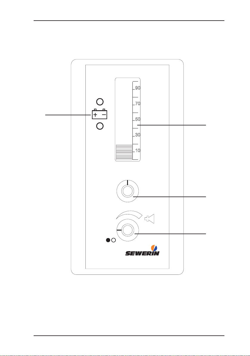
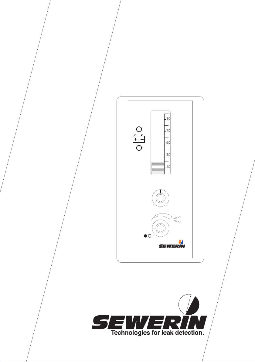
Design of the FERROTEC® 300 and FERROTEC® 350 (with Display)
90
70
4
50
3
30
10
4
3
2
5
6
2
1
7
1
FERROTEC® 350
Page 4

Operating Instructions
23.10.2008 – V2.XXX – 102661 – en
FERROTEC ® 300
FERROTEC ® 350
Page 5
Warranty & Used symbols
To ensure reliable operation and safety, it is required to pay attention to
the following notes.
Hermann Sewerin GmbH is not liable for damage caused by failure to
comply with these notes. The guarantee and liability conditions of the
sales and delivery conditions of Hermann Sewerin GmbH are not extended by the following notes.
This product may only be taken into operation after reading thoroughly
the accompanying operating instructions.
This product may only be used for intended applications.
This product is destined for industrial and commercial applications.
Repairs may only be performed by the manufacturer or appropriately
trained staff.
The manufacturer is not liable for damage resulting from arbitrary mo-
difi cations of the product.
Only spare parts may be used which are approved by Hermann Sewerin
GmbH.
Only approved battery types may be used.
Technical changes within the scope of further development reserved.
Note:
This symbol refers to information and useful tips which
are exceeding the basic operating procedures.
Page 6

Contents Page
1 Designated purpose and function .........................................1
2 Operation .................................................................................2
3 Carrying ....................................................................................3
4 Notes on operation .................................................................4
4.1 Sensitivity ..................................................................................4
4.2 Location and shape of an object ..............................................4
4.3 Distinguishing between large and small objects .......................5
4.4 Highly magnetised objects ........................................................6
4.5 Searching in the vicinity of interference sources ......................6
4.6 Cast-iron pipes ..........................................................................7
4.7 Snow and water ........................................................................7
5 Battery display/Changing the battery ...................................8
6 Maintenance, malfunctions .................................................... 9
6.1 Function testing ........................................................................9
7 Accessories ...........................................................................10
8 Specifi cations ........................................................................11
9 Appendix ................................................................................12
9.1 Declarations of Conformity .....................................................12
Page 7

1
Designated purpose and function1
Designated purpose and function1
The FERROTEC is designed to locate concealed ferromagnetic
objects (steel, iron, cast iron). It is particularly suitable for the
location of valve rods, cap sills, metal shaft and tank covers,
marking nails and marking magnets.
There are 2 sensors in the sensor rod which react to changes
in the earth‘s magnetic eld caused by ferromagnetic materials.
The change in the earth‘s magnetic eld does not reach maxi-
mum strength until the object has been motionless for several
days or even weeks, so objects placed on the ground for testing
purposes are often difcult to locate.
The FERROTEC design excludes interference and mislocation
due to non-ferrous metals.
Fig. 1
Object in the ground, representation of magnetic-eld lines. The magnetic eld
at the end of the sensor rod, sensor A, is not the same as at sensor B.
Differences in the earth‘s magnetic eld increase with proximity
to the object. This causes an indication in the form of a rise in the
loudspeaker frequency. With the FERROTEC 350 this increase is
also shown in the bar-graph display. When the pitch is highest or
the bar largest, the sensor rod is pointing at an object.
Page 8

2
Operation2
Operation2
Note:
Please avoid wearing shoes with steel insoles or
steel toe-caps when using the FERROTEC as these
will disturb the location results.
The device is switched on with the on/off switch (item 1). This z
also sets the required volume.
Sensitivity is then set with the knob (item 2). The default setting z
is approximtely “4”.
Check function by placing the z FERROTEC close to a suitable
object (e.g a car, an iron post or a hydrant cap which is not
concealed). This must cause a rise in the pitch of the sound,
plus (on the FERROTEC 350) a clear increase in the size of
the bar-graph display (item 3). See „Battery display/Changing
the battery“ and „Function testing“.
After use the z FERROTEC is switched off with the on/off switch
(item 1).
Page 9

3
Carrying3
Carrying3
This illustration shows how the device should be carried:
The sensor rod should be kept as close as possible to the
ground.
Once the presence of an object has been detected the FERROTEC
should be held vertically. The exact location of the object is now
determined by passing the device over the ground in the form of
a cross.
Page 10

4
Notes on operation4
Notes on operation4
Sensitivity4.1
If the object to be located is small or at a great depth, select a
higher sensitivity (5 – 7 on the scale). If you wish to avoid interference from small objects, a low sensitivity (1 – 3 on the scale)
should be selected.
Valve rods and street caps show up well at a depth of 30 cm
when the sensitivity is set to “4”.
Practical tip: when attempting to locate a concealed manhole
cover, rst set the sensitivity by checking it against a similar visible cover.
Location and shape of an object4.2
Fig. 2
Differing signals:
a) a maximum for a vertical object (e.g a marking pipe)
b) two maxima for horizontal objects (e.g a pipe or cover) at the edges or
ends.
Page 11

5
Notes on operation4
Distinguishing between large and small objects4.3
This is important, because small objects like nails, screws and
the like are displayed.
There are two ways of distinguishing between them.
With small objects the display decreases more markedly as the z
distance increases than it does with larger objects.
Fig. 3
Example: a screw and a boundary-mark pipe are displayed when the sensor
rod is passed over the ground at a distance of 5 cm (a). At a distance of 30 cm
- with the same sensitivity - only the boundarymark pipe is displayed (b).
Larger objects appear broader in the display than smaller z
ones.
You should therefore vary the sensitivity setting and the distance
of the sensor rod from the ground depending on the size of the
object you are looking for.
Page 12

6
Notes on operation4
Highly magnetised objects4.4
With highly magnetised objects (for example marking pipes or
permanent magnets) the FERROTEC may give apparently misleading readings. The following illustration shows the signal curve
(C) of a highly magnetised object.
Fig. 4
The superimposition of the magnetic eld of the object on that
of the earth produces zones in which the effects cancel each
other out. As a result the signal curve shows a minimum next to
the object at A and B.
In practical use care should therefore be taken that the rst
change in pitch is not taken as an indication of the precise loca-
tion. It is advisable to subject areas which have given the rst
indication to an extensive and critical search.
Searching in the vicinity of interference sources4.5
In the vicinity of steel fences, grilles, vehicles and the like, in-
terference naturally makes location difcult - if not impossible.
Care should be taken to hold the device vertical and to set a
low sensitivity.
Page 13

7
Notes on operation4
Cast-iron pipes4.6
It may be possible to locate cast-iron pipes if there is no interference and if they run more or less from north to south. They
generate the strongest signal at the joints (sleeves).
Proceed as follows:
Select maximum sensitivity. z
Hold the sensor rod vertically at a distance of 30 – 40 cm z
above the ground. Slowly walk the terrain, moving the sensor
rod slowly.
Approximately mark the display maxima. z
Search again directly above the ground with the sensor rod z
vertical.
The more the orientation of the pipe diverges from the northsouth line, the more the location result may differ from there
actual position.
Snow and water4.7
The sensor rod is waterproof, so it can be used in snow or water.
Page 14

8
Battery display/Changing the battery5
Battery display/Changing the battery5
The battery display (pos. 4) next to the battery symbol shows
the battery capacity with two LED:
Green LED (above) ashes: battery is in good order
Red LED (below) glows permanently: battery is discharched,
the battery has to be
changed
A heavily discharged battery may reduce the sensitivity and dynamics of the acoustic signal. The battery should therefore be
changed regularly.
The slotted-head screws on the side of the device are released
by rotating them half a turn. The battery compartment under the
cover is extracted for the battery to be removed. Make sure the
cover is properly replaced to protect the battery from water.
Page 15

9
Maintenance, malfunctions6
Maintenance, malfunctions6
No maintenance is necessary apart from changing the battery. In
the event of malfunctions (no display, interrupted display), check
the battery condition and make sure the battery is making proper
contact with its holder.
Function testing6.1
A function test may be carried out under the following conditions:
An iron rod 10 mm in diameter and 300 mm long, which has been
in the ground in a vertical position for at least a week, must be
detectable at a distance of about 50 cm at the maximum sensitivity setting.
Page 16

10
Accessories7
Accessories7
Carrying bag FERROTEC
300/350
Part-No.: 3204-0028
with polyethylene insert z
Headphones K3
Part-No.: EZ13-11000
Robust and spray-protected z
headphones with changeable
cushion.
Page 17

11
Specications8
Specications8
Operating-/storage
temperature:
-20 °C – +70 °C
Total Length: approx. 130 cm
Detection: up to 1,5 m depth
Power supply: Block battery
(9V, 1200 mAh), operating time up
to 18 hours
Protection type: according to IP54, Sensor rod
IP68
Visual display: LCD bar-display with the
FERROTEC 350)
Acoustic display: integrated loudspeaker or
headphones
Page 18

12
Appendix9
Appendix9
Declaration of Conformity9.1
Konformitätserklärung / Declaration of Conformity
Gerätebezeichnung:
Type of Product:
Batteriebetriebenes Magnetometer
battery operated magnetometric instrument
Geräte-Typ:
Product Name:
Ferrotec 300
Fabrikations-Nr.:
Fabr. No.:
051 11 xxxx
Hiermit erklären wir, dass oben genanntes Produkt mit der/den folgenden Norm(en) oder
normativen Dokument(en) übereinstimmt. Bei einer mit uns nicht abgestimmten
Änderung des Produkts verliert diese Erklärung ihre Gültigkeit.
We hereby declare that the above product complies with the following norms or
standardized directives. In the event of any modification of this product which has not
been authorized by us, this declaration becomes invalid.
Norm(en)/Norm(s):
DIN EN 61000-6 Teil 1 und 2
EMV – Fachgrundnorm Störfestigkeit
Generic Immunity Standard
DIN EN 61000-6 Teil 3 und 4
EMV – Fachgrundnorm Störaussendung
Generic Emission Standard
Gemäß den Bestimmungen der Richtlinie(n)/The unit complies with:
89/336/EWG
EG-Richtlinie: Elektromagnetische Verträglichkeit
EG-Directive: Electromagnetic Compatibility
92/31/EWG
Änderung dazu/amendment to above
93/68/EWG
Änderung dazu/amendment to above
Gütersloh, den 24.10.2006
HERMANN SEWERIN GMBH
(Geschäftsführer/Managing Director)
Page 19

13
Appendix9
Konformitätserklärung / Declaration of Conformity
Gerätebezeichnung:
Type of Product:
Batteriebetriebenes Magnetometer
Battery operated magnetometric instrument
Geräte-Typ:
Product Name:
Ferrotec 350
Fabrikations-Nr.:
Fabr. No.:
051 12 xxxx
Hiermit erklären wir, dass oben genanntes Produkt mit der/den folgenden Norm(en) oder
normativen Dokument(en) übereinstimmt. Bei einer mit uns nicht abgestimmten
Änderung des Produkts verliert diese Erklärung ihre Gültigkeit.
We hereby declare that the above product complies with the following norms or
standardized directives. In the event of any modification of this product which has not
been authorized by us, this declaration becomes invalid.
Norm(en)/Norm(s):
DIN EN 61000-6 Teil 1 und 2
EMV – Fachgrundnorm Störfestigkeit
Generic Immunity Standard
DIN EN 61000-6 Teil 3 und 4
EMV – Fachgrundnorm Störaussendung
Generic Emission Standard
Gemäß den Bestimmungen der Richtlinie(n)/The unit complies with:
89/336/EWG
EG-Richtlinie: Elektromagnetische Verträglichkeit
EG-Directive: Electromagnetic Compatibility
92/31/EWG
Änderung dazu/amendment to above
93/68/EWG
Änderung dazu/amendment to above
Gütersloh, den 24.10.2006
HERMANN SEWERIN GMBH
(Geschäftsführer/Managing Director)
Page 20

Hermann Sewerin GmbH
Robert-Bosch-Straße 3 · 33334 Gütersloh · Germany
Telefon +49 5241 934-0 · Telefax +49 5241 934-444
www.sewerin.com · info@sewerin.com
23.10.2008 b – 102661 – en
 Loading...