

Page 1
Operating-
Instructions
102424
Page 2

Measurable success by Sewerin equipment
You settled on a precision instrument.
A good choice!
Our equipment stands out for guaranteed safety, optimal output and efficiency .
They correspond with the national and international guide-lines.
These operating instructions will help you to handle the instrument quickly and
competently.
Please pay close attention to our operating instructions before usage.
In case of further queries our staff is at your disposal at any time.
Yours
Hermann Sewerin GmbH
Robert-Bosch-Straße 3
D-33334 Gütersloh
: +49 - (0) - 52 41/9 34-0
FAX : +49 - (0) - 9 34-4 44
http:// www.sewerin.com
Page 3
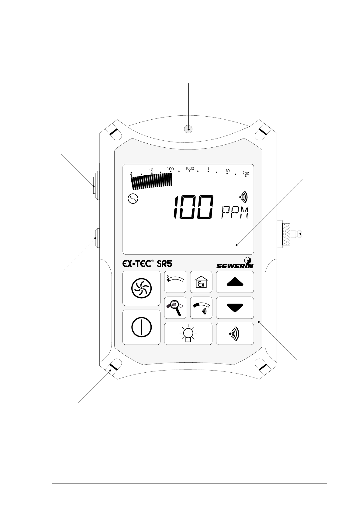
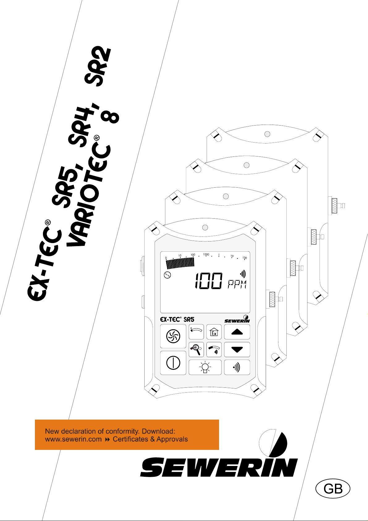
Design of the: EX-TEC® SR5
7
1
2
6
3
4
5
1
Page 4

Notes
2
Page 5

EX-TEC® SR 5, SR4, SR2
VARIOTEC® 8
Operating InstructionsOperating Instructions
Operating Instructions
Operating InstructionsOperating Instructions
102424 - 04/20.08.1999
................
........
................
pages 3 - 52pages 3 - 52
pages 3 - 52
pages 3 - 52pages 3 - 52
3
Page 6

For your safety *For your safety *
For your safety *
For your safety *For your safety *
The law governing technical equipment (the Law on the Safety of Appliances)
of 24.06.1968 (BGBl.I, page 717) as amended by the Amendment Law of
13.08.1979 (BGBl.I, page 1432) requires the following matters to be drawn
to your attention:
Comply with the Operating InstructionsComply with the Operating Instructions
Comply with the Operating Instructions.
Comply with the Operating InstructionsComply with the Operating Instructions
Before operating or adjusting the appliance you must be thoroughly familiar
with this operating manual. You must comply with it in every respect.
The appliance is designed only for the application described and for
industrial (commercial) use.
Liability for Function and/or DamageLiability for Function and/or Damage
Liability for Function and/or Damage
Liability for Function and/or DamageLiability for Function and/or Damage
Liability for the functioning of the appliance passes to the owner or operator
in all cases in which the appliance has been improperly maintained or
repaired by persons not associated with SEWERIN Service or if it has been
used for a purpose not in accordance with its designated application.
You should therefore always use original SEWERIN accessories with the
EX-TEC® SR 5, SR4, SR2 and VARIOTEC® 8.
Hermann Sewerin GmbH accepts no responsibility for damage due to a
failure to comply with the foregoing instructions. The guarantee and liability
terms of the Hermann Sewerin GmbH terms of sale and supply are not
extended by the foregoing.
We reserve the right to make technical changes in the course of continued
development.
HERMANN SEWERIN GMBH
* All references to laws, statutes and norms relate to the legislation of the Federal Republic of
Germany.
4
Page 7

ContentsContents
Contents
ContentsContents
pagepage
page
pagepage
For your safetyFor your safety
For your safety
For your safetyFor your safety
1.01.0
1.0 The EX-TEC® SR5, SR4, SR2 and VARIOTEC® 8
1.01.0
........................................................................................................................................................................
....................................................................................
........................................................................................................................................................................
models .............
4 4
4
4 4
6 6
6
6 6
1.1 Tests ............................................................................................. 8
1.2 Probe systems ............................................................................. 9
2.02.0
2.0
2.02.0
Measuring operationMeasuring operation
Measuring operation
Measuring operationMeasuring operation
................................................................................................................................
................................................................
................................................................................................................................
1 1
1
1 1
2.1 Switching on ................................................................................ 11
2.2 Illumination and contrast ............................................................. 12
2.3 Pump operation .......................................................................... 13
2.4 Alarm signal and volume ............................................................ 14
2.5 Alarm threshold value ................................................................. 14
2.6 Switching measuring ranges ...................................................... 15
2.7 Zero-point adjustment ................................................................ 16
2.8 Workplace monitoring ................................................................ 16
2.9 Battery alarm............................................................................... 18
2.10 Switching off ............................................................................... 18
3.03.0
3.0
3.03.0
Charging techniqueCharging technique
Charging technique
Charging techniqueCharging technique
..................................................................................................................................
.................................................................
..................................................................................................................................
19 19
19
19 19
11
1
11
4.04.0
4.0
4.04.0
Inspection, testing and maintenanceInspection, testing and maintenance
Inspection, testing and maintenance
Inspection, testing and maintenanceInspection, testing and maintenance
........................................................................
....................................
........................................................................
21 21
21
21 21
4.1 Test sets ..................................................................................... 22
4.2 Test gases .................................................................................. 24
4.3 Function testing .......................................................................... 25
5.05.0
5.0
5.05.0
6.06.0
6.0
6.06.0
7.07.0
7.0
7.07.0
8.08.0
8.0
8.08.0
9.09.0
9.0
9.09.0
10.010.0
10.0
10.010.0
EC-TEC-T
EC-T
EC-TEC-T
Declarations of conformityDeclarations of conformity
Declarations of conformity
Declarations of conformityDeclarations of conformity
AdjustmentAdjustment
Adjustment
AdjustmentAdjustment
TT
echnical specificationsechnical specifications
T
echnical specifications
TT
echnical specificationsechnical specifications
TT
echnical dataechnical data
T
echnical data
TT
echnical dataechnical data
AccessoriesAccessories
Accessories
AccessoriesAccessories
Error messagesError messages
Error messages
Error messagesError messages
Parts subject to wearParts subject to wear
Parts subject to wear
Parts subject to wearParts subject to wear
ype Examinations Certificateype Examinations Certificate
ype Examinations Certificate
ype Examinations Certificateype Examinations Certificate
................................................................................................................................................................
................................................................................
................................................................................................................................................................
..................................................................................................................
.........................................................
..................................................................................................................
....................................................................................................................................................
..........................................................................
....................................................................................................................................................
............................................................................................................................................................
..............................................................................
............................................................................................................................................................
..............................................................................................................................................
.......................................................................
..............................................................................................................................................
............................................................................................................................
..............................................................
............................................................................................................................
............................................................................................................................
..............................................................
............................................................................................................................
....................................................................................................
..................................................
....................................................................................................
26 26
26
26 26
34 34
34
34 34
37 37
37
37 37
39 39
39
39 39
40 40
40
40 40
42 42
42
42 42
43 43
43
43 43
47 47
47
47 47
TT
est reportsest reports
T
est reports
TT
est reportsest reports
................................................................................................................................................................................
........................................................................................
................................................................................................................................................................................
51 51
51
51 51
5
Page 8

1.01.0
The The
1.0
The EX-TEC® SR5, SR4, SR2 and VARIOTEC® 8
1.01.0
The The
modelsmodels
models
modelsmodels
This family of detectors consists of a total of four combined detectors
for the following uses:
EX-TEC® SR5 (Ex-protected)
Gas detectionGas detection
Gas detection
•
Gas detectionGas detection
above-ground gas detection for
pipeline monitoring (ppm range)
Interior installationsInterior installations
Interior installations
•
Interior installationsInterior installations
leak detection for pipelines in
buildings (ppm range)
Workplace monitoringWorkplace monitoring
•
Workplace monitoring
Workplace monitoringWorkplace monitoring
monitoring proximity to the
Lower Explosive Limit (%LEL
range)
LocationLocation
Location
•
LocationLocation
concentration measurement in
probe holes (vol.% range)
Gasing and inertisationGasing and inertisation
Gasing and inertisation
•
Gasing and inertisationGasing and inertisation
concentration measurement in
pipelines (vol.% range)
EX-TEC® SR4 (Ex-protected)
Workplace monitoringWorkplace monitoring
•
Workplace monitoring
Workplace monitoringWorkplace monitoring
monitoring proximity to the
Lower Explosive Limit (%LEL
range)
LocationLocation
Location
•
LocationLocation
concentration measurement in
probe holes (vol.% range)
Gasing and inertisationGasing and inertisation
Gasing and inertisation
•
Gasing and inertisationGasing and inertisation
concentration measurement in
pipelines (vol.% range)
6
Page 9
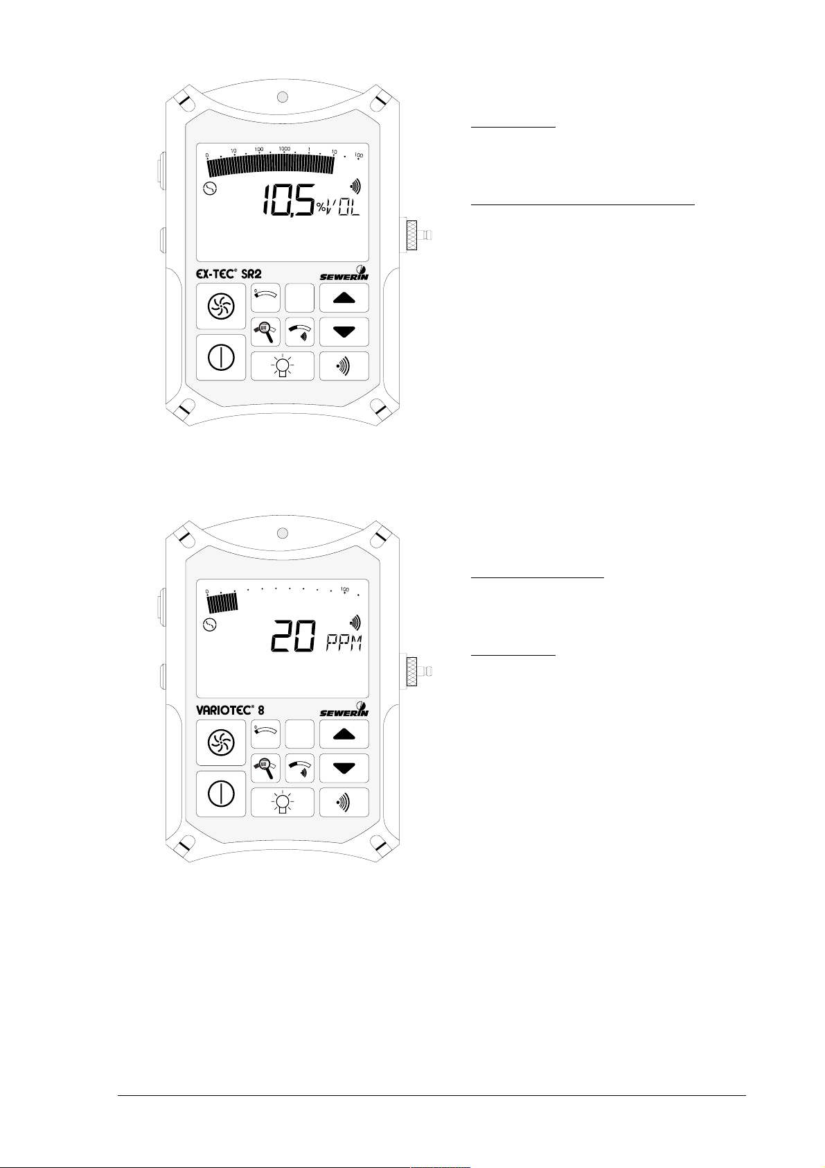
EX-TEC® SR2 (Ex-protected)
LocationLocation
Location
•
LocationLocation
concentration measurement in
probe holes (vol.% range)
Gasing and inertisationGasing and inertisation
Gasing and inertisation
•
Gasing and inertisationGasing and inertisation
concentration measurement in
pipelines (vol.% range)
VARIOTEC® 8
Gas detectionGas detection
•
Gas detection
Gas detectionGas detection
above-ground gas detection for
pipeline monitoring (ppm range)
LocationLocation
Location
•
LocationLocation
concentration measurement in
probe holes (vol.% range)
7
Page 10

1.11.1
TT
1.1
1.11.1
estsests
T
ests
TT
estsests
Passive explosion protectionPassive explosion protection
Passive explosion protection
Passive explosion protectionPassive explosion protection
The EX-TEC® SR5, EX-TEC® SR4 and EX-TEC® SR2 models are explosion-
proof in accordance with European norms (CENELEC):
EC prototype test certificate: PTB 96 ATEX 2166
Classification: II 2 G EEx ib d IIB T4
Test institute: Physikalische-Technische
Bundesanstalt, Braunschweig
Active explosion protectionActive explosion protection
Active explosion protection
Active explosion protectionActive explosion protection
The EX-TEC® SR5 and EX-TEC® SR4 have also been tested for
functional safety in the Workplace Monitoring (WPM) field:
Test report: PFG no. 41300897
Test institute: DMT-Gesellschaft für Forschung
und Prüfung mbH, Essen
The test certificates can be found on and after page 43.
8
Page 11

1.21.2
Probe systemsProbe systems
1.2
Probe systems
1.21.2
Probe systemsProbe systems
- Probes for the survey of gas distributions networks -- Probes for the survey of gas distributions networks -
- Probes for the survey of gas distributions networks -
- Probes for the survey of gas distributions networks -- Probes for the survey of gas distributions networks -
Carpet probeCarpet probe
Carpet probe
Carpet probeCarpet probe
for checking stable surfaces.
The sample is drawn into an
excrescence in a neoprene mat
in contact with the surface with no
extraneous emissions.
Bell probe,Bell probe,
Bell probe,
Bell probe,Bell probe,
telescopic bell probetelescopic bell probe
telescopic bell probe
telescopic bell probetelescopic bell probe
for checking unstable and
overgrown surfaces.
It can be used in confined
spaces, e.g. between parked
cars or in front gardens.
- Probes for localisation -- Probes for localisation -
- Probes for localisation -
- Probes for localisation -- Probes for localisation -
Search probeSearch probe
Search probe
Search probeSearch probe
for measuring concentrations in
probe holes,
with a rigid rubber cone to seal
off the probe hole,
2 different probe tips (length 245
mm or 345 mm),
carbon-dioxide filter to filter out
traces of CO
2
9
Page 12

- Probes for hollow spaces -- Probes for hollow spaces -
- Probes for hollow spaces -
- Probes for hollow spaces -- Probes for hollow spaces -
Floating probeFloating probe
Floating probe
Floating probeFloating probe
for measuring concentrations in
pits,
with suction vent and hose
connection
Divisible handprobeDivisible handprobe
Divisible handprobe
Divisible handprobeDivisible handprobe
for the detection of leaks in pipes
installed in poorly accessible places,
measuring of concentration in containers, overall length 900 mm
- Probes for house service lines -- Probes for house service lines -
- Probes for house service lines -
- Probes for house service lines -- Probes for house service lines -
Flexible hand probesFlexible hand probes
Flexible hand probes
Flexible hand probesFlexible hand probes
for the detection of leaks in
house service lines, handle with
flexible swan neck and probe
hose, overall lengths 360 mm or
660 mm
☞
Except with the carpet probe , a probe hoseExcept with the carpet probe , a probe hose
Except with the carpet probe , a probe hose
Except with the carpet probe , a probe hoseExcept with the carpet probe , a probe hose
should always be used should always be used
should always be used
should always be used should always be used
withwith
a hydrophobic filter ! a hydrophobic filter !
with
a hydrophobic filter !
withwith
a hydrophobic filter ! a hydrophobic filter !
10
Page 13

2.02.0
Measuring operationMeasuring operation
2.0
Measuring operation
2.02.0
Measuring operationMeasuring operation
☞
ItemItem
Item
ItemItem
1 alarm lamp optical warning
2 LCD display display of gas
3 probe connection connection to the probes
4 buttonboard operating the detector
Please fold out the illustration inside thePlease fold out the illustration inside the
Please fold out the illustration inside the
Please fold out the illustration inside thePlease fold out the illustration inside the
front cover !front cover !
front cover !
front cover !front cover !
DescriptionDescription
Description
DescriptionDescription
FunctionFunction
Function
FunctionFunction
when alarm thresholds are
exceeded
concentrations and
operating conditions
described
5 harness for portable systems
6 outlet for gas sample
7 buzzer acoustic warning
when alarm thresholds are
exceeded
2.12.1
Switching onSwitching on
2.1
Switching on
2.12.1
Switching onSwitching on
• press the
detection mode) or
(workplace-monitoring mode, p.
16 ff.) for approx. 2 seconds
• optical and acoustic control signal
(items 1 and 7) operate for approx.
2 seconds
on/off buttonon/off button
on/off button (gas-
on/off buttonon/off button
WPM button WPM button
WPM button
WPM button WPM button
11
Page 14
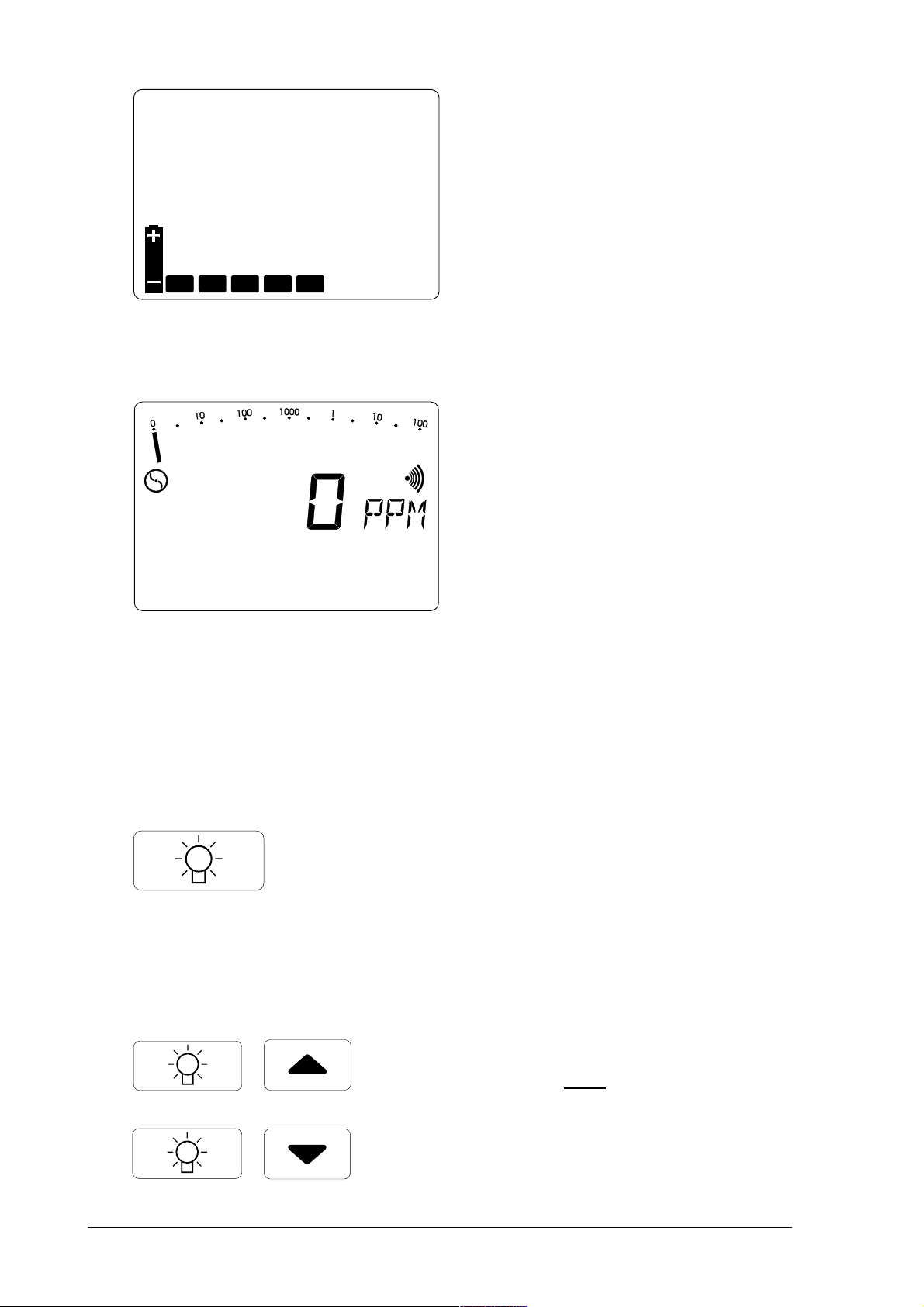
• display of available operating
hours in the form of bars (e.g. 5
hours)
• the integral pump operates at
maximum power
• wait until the zero point has
established itself in fresh air
(approx. 2-3 minutes):
EX-TEC® SR5 and VARIOTEC® 8:
0 PPM0 PPM
☞
0 PPM
0 PPM0 PPM
2.22.2
Illumination and contrastIllumination and contrast
2.2
Illumination and contrast
2.22.2
Illumination and contrastIllumination and contrast
(after flashing stops)
EX-TEC® SR4 and EX-TEC® SR2:
0,0 %VOL0,0 %VOL
☞
0,0 %VOL
0,0 %VOL0,0 %VOL
• pressing the
switches the LCD illumination on
and off
• the illumination automatically
switches off approx. 4 minutes
after being switched on
light buttonlight button
light button
light buttonlight button
12
• simultaneously pressing the light
andand
button
increases or reduces the contrast
of the LCD display
and a cursor button
andand
Page 15

2.32.3
Pump operationPump operation
2.3
Pump operation
2.32.3
Pump operationPump operation
• pressing the
switches the pump on and off
• the corresponding symbol
appears in or disappears from
the LCD display (item 2)
• this enables the pump function to
be checked
pump buttonpump button
pump button
pump buttonpump button
☞
Altering the pump powerAltering the pump power
Altering the pump power
Altering the pump powerAltering the pump power
(available only on the (available only on the
(available only on the EX-TEC® SR5
(available only on the (available only on the
• simultaneously pressing the
pump button
button increases or reduces the
pump power
gas detectiongas detection
☞
gas detection
gas detectiongas detection
for above-ground gas detection
(pipeline monitoring) always use
maximum pump powermaximum pump power
maximum pump power
maximum pump powermaximum pump power
house service lineshouse service lines
☞
house service lines
house service lineshouse service lines
) !) !
) !
) !) !
andand
and one cursor
andand
for detecting leaks in pipelines
inside buildings always use
minimum pump powerminimum pump power
minimum pump power
minimum pump powerminimum pump power
13
Page 16
2.42.4
Alarm signal and volumeAlarm signal and volume
2.4
Alarm signal and volume
2.42.4
Alarm signal and volumeAlarm signal and volume
• pressing the
signal buttonsignal button
signal button
signal buttonsignal button
switches the alarm signal on and
off
• the corresponding symbol
appears in or disappears from
the LCD display (item 2)
• this enables the alarm signal to
be checked
• simultaneously pressing the
signal button
andand
and one cursor
andand
button increases or reduces the
buzzer volume (item 7)
2.52.5
Alarm threshold valueAlarm threshold value
2.5
Alarm threshold value
2.52.5
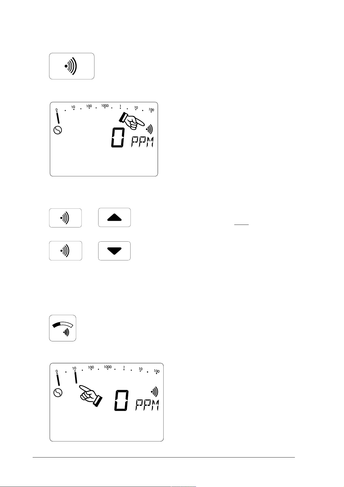
Alarm threshold valueAlarm threshold value
14
• when the
buttonbutton
button is held down
buttonbutton
threshold valuethreshold value
threshold value
threshold valuethreshold value
• the alarm threshold value (e.g. 10
PPM) flashes in the full-range
display
Page 17
2.62.6
Switching measuring rangesSwitching measuring ranges
2.6
Switching measuring ranges
2.62.6
Switching measuring rangesSwitching measuring ranges
• holding down the threshold value
button
andand
and repeatedly pressing
andand
one cursor button increases or
reduces the alarm threshold value
• this value is preserved even when
the detector is switched off
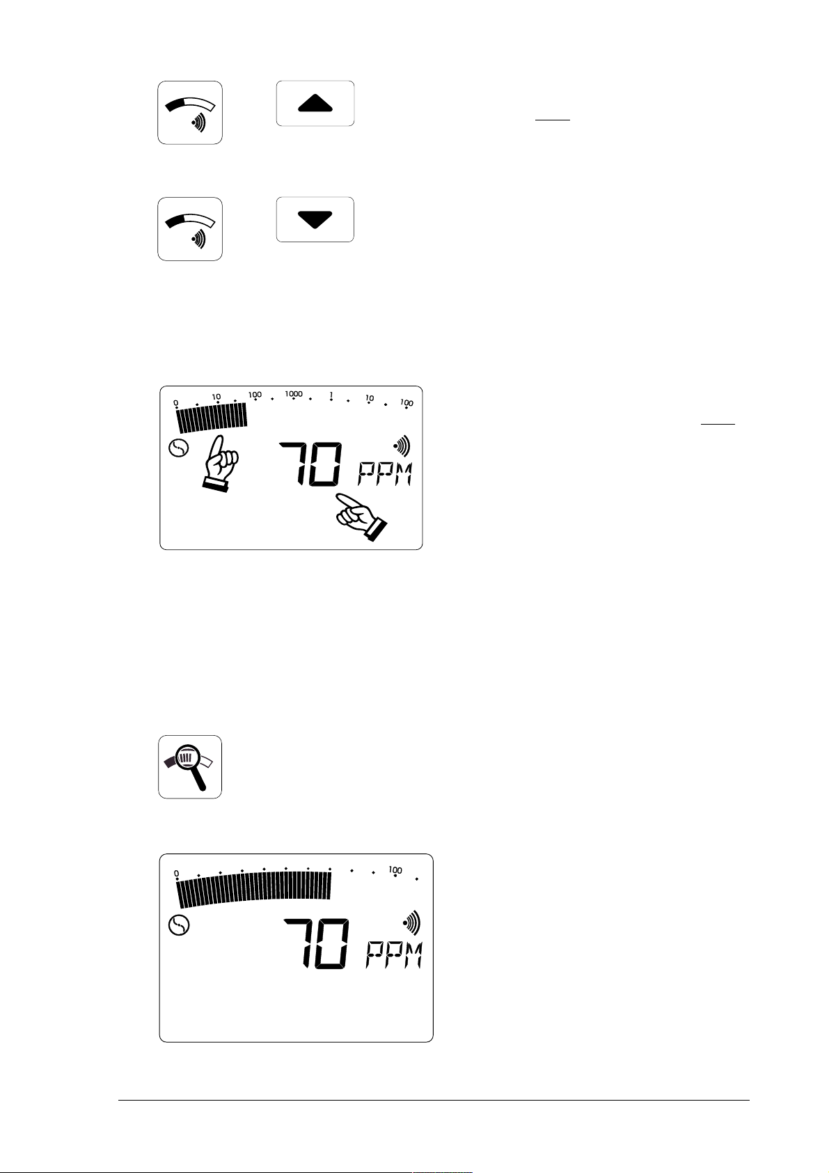
• all detectors have an
displaydisplay
display (above, full range)
displaydisplay
digital displaydigital display
digital display (below);
digital displaydigital display
analogueanalogue
analogue
analogueanalogue
andand
and a
andand
both scales indicate the same
concentration (e.g. 70 PPM)
• the
full rangefull range
full range is a logarithmic
full rangefull range
scale covering the range:
0 PPM ... 100 %VOL
• here the display of low
concentrations is intensified;
the measurement result can be
read off from the digital display
• repeatedly pressing the
buttonbutton
button switches between the
buttonbutton
optimum rangesoptimum ranges
and
optimum ranges
optimum rangesoptimum ranges
zoomzoom
zoom
zoomzoom
fullfull
full
fullfull
• depending on the concentration,
switching between the following
measurement ranges is
automatic:automatic:
automatic:
automatic:automatic:
0 ... 10 PPM 0 ... 1 %VOL
0 ... 100 PPM 0 ... 10 %VOL
0 ... 1,000 PPM 0 ... 100 %VOL
• the optimum measurement range
in this example is 0 ... 100 PPM
15
Page 18

2.72.7
Zero-point adjustmentZero-point adjustment
2.7
Zero-point adjustment
2.72.7
Zero-point adjustmentZero-point adjustment
• repeatedly pressing one of the
cursor buttons while holding down
the zoom button switches
manually to the required display
range
• if the detector fails to reach its
zero point of
0 PPM0 PPM
0 PPM or
0 PPM0 PPM
after flushing with copious fresh
air, pressing the
buttonbutton
button enables you to adjust it
buttonbutton
manually
0,00,0
%VOL%VOL
0,0
%VOL
0,00,0
%VOL%VOL
zero pointzero point
zero point
zero pointzero point
2.82.8
Workplace monitoringWorkplace monitoring
2.8
Workplace monitoring
2.82.8
Workplace monitoringWorkplace monitoring
☞
This function is available only with the This function is available only with the
This function is available only with the EX-TEC® SR5
This function is available only with the This function is available only with the
and and
and EX-TEC® SR4
and and
• the reading display flashes while
the adjustment is being carried
out
• measurement cannot be
resumed until
stops
detectors ! detectors !
detectors !
detectors ! detectors !
• this function is switched on by
pressing the
mm
monitoring)
mm
afteafte
after the flashing
afteafte
WPM WPM
WPM (
WPM WPM
buttonbutton
button
buttonbutton
ww
work
ww
pp
place
pp
16
• the detector can also be switched
on by pressing this button
Page 19

• this measuring range is used to
monitor proximity to the
ll
lower
(
ll
ee
explosion
ee
ll
limit)
ll
LELLEL
LEL
LELLEL
• after approx. 8 seconds' warm-
up time a stable zero point is
reached
• the pump runs at minimum power
and the acoustic operating signal
(item 7) sounds every 5 seconds
• when the pre-set threshold of
20 %LEL is exceeded
methane:methane:
methane: 20 %LEL = 0,88 %VOL
methane:methane:
(display = 0,90 %VOL)
propane:propane:
propane: 20 %LEL = 0,34 %VOL
propane:propane:
advance alarmadvance alarm
the
advance alarm is triggered
advance alarmadvance alarm
both optically (item 1) and
acoustically (item 7)
• the advance alarm is an
intermittent tone quite distinct
from the operating signal;
ceases after a certain periodceases after a certain period
it
ceases after a certain period
ceases after a certain periodceases after a certain period
and cannot be cleared
• if the concentration exceeds
100 %LEL
methane:methane:
methane:100 %LEL = 4,40 %VOL
methane:methane:
propane:propane:
propane:100 %LEL = 1,70 %VOL
propane:propane:
main alarmmain alarm
the
main alarm is triggered
main alarmmain alarm
optically (item 1) and acoustically
(item 7)
17
Page 20

2.92.9
Battery alarmBattery alarm
2.9
Battery alarm
2.92.9
Battery alarmBattery alarm
• the main alarm is a continuous
tone quite distinct from the
operating signal;
continues indefinitelycontinues indefinitely
it
continues indefinitely and
continues indefinitelycontinues indefinitely
cannot be cleared
Cancelling the main alarm:Cancelling the main alarm:
•
Cancelling the main alarm:
Cancelling the main alarm:Cancelling the main alarm:
switch to location operation (press
the pump button for approx. 2
seconds ) or switch the detector
off
• if the battery symbol appears in
the LCD display, at least 15
minutes' operating time remains;
after that the detector must be
recharged
2.10Switching off2.10Switching off
2.10Switching off
2.10Switching off2.10Switching off
• in workplace-monitoring mode
the battery alarm is accompanied
by a "double beep" to distinguish
it from the operating signal
• Press the
on/off buttonon/off button
on/off button for
on/off buttonon/off button
approx. 2 seconds
• the optical and acoustic
monitoring signals (items 1 and
7) operate for approx. 2 seconds
18
• remaining operating hours are
displayed in the form of bars
Page 21

3.03.0
Charging techniqueCharging technique
3.0
Charging technique
3.03.0
Charging techniqueCharging technique
☞
When fully charged the detectors have a
operating time with the pump running.
For charging you need the
which can be used either in the workshop or in the standby vehicle.
The The
The EX-TEC® SR5,
The The
must not be recharged in an explosive gasmust not be recharged in an explosive gas
must not be recharged in an explosive gas
must not be recharged in an explosive gasmust not be recharged in an explosive gas
atmosphere !atmosphere !
atmosphere !
atmosphere !atmosphere !
SR4, SR2
HS charging adapterHS charging adapter
HS charging adapter (see illustration),
HS charging adapterHS charging adapter
and and
and VARIOTEC® 8
and and
maximummaximum
maximum of 8 hours'
maximummaximum
The following items can be
connected to the side of the
charging adapter:
• 230 V mains power pack ≈,
detectors detectors
detectors
detectors detectors
• 12 V= vehicle adapter,
• 24 V= vehicle adapter.
ChargingCharging
Charging
ChargingCharging
Switch the detector off and plug it into the charger. A display of the
following type appears:
• the detector has 5 operating hours
left (= 5 bars) and will take 3 hours
to become fully charged
• if it is fully charged all the bars are
visible and the number display
disappears
• the detector can be left in the
charger until it is next needed
19
Page 22

Spontaneous dischargeSpontaneous discharge
Spontaneous discharge
Spontaneous dischargeSpontaneous discharge
If the detector is
nickel-cadmium battery spontaneously discharges, thus reducing the
available operating hours.
After a maximum of 30 days the detector indicator shows that there are
no operating hours left, and it must be recharged.
not connected to the charger when switched off, the
☞
Short periods of operation and prolonged disuseShort periods of operation and prolonged disuse
Short periods of operation and prolonged disuse
Short periods of operation and prolonged disuseShort periods of operation and prolonged disuse
may lead in the long term to the so-called "memorymay lead in the long term to the so-called "memory
may lead in the long term to the so-called "memory
may lead in the long term to the so-called "memorymay lead in the long term to the so-called "memory
effect", in which the display indicates a highereffect", in which the display indicates a higher
effect", in which the display indicates a higher
effect", in which the display indicates a highereffect", in which the display indicates a higher
battery capacity than is actually available. This canbattery capacity than is actually available. This can
battery capacity than is actually available. This can
battery capacity than is actually available. This canbattery capacity than is actually available. This can
be avoided by fully discharging -the detectorbe avoided by fully discharging -the detector
be avoided by fully discharging -the detector
be avoided by fully discharging -the detectorbe avoided by fully discharging -the detector
regularly (e.g. once a month), leaving it switched onregularly (e.g. once a month), leaving it switched on
regularly (e.g. once a month), leaving it switched on
regularly (e.g. once a month), leaving it switched onregularly (e.g. once a month), leaving it switched on
until it automatically switches off, then recharginguntil it automatically switches off, then recharging
until it automatically switches off, then recharging
until it automatically switches off, then recharginguntil it automatically switches off, then recharging
it !it !
it !
it !it !
20
Page 23

4.04.0
Inspection, testing and maintenanceInspection, testing and maintenance
4.0
Inspection, testing and maintenance
4.04.0
Inspection, testing and maintenanceInspection, testing and maintenance
DVGW work sheet G 465/IV requires detectors to be inspected,
tested and maintained.
Sensitivity testingSensitivity testing
Sensitivity testing
Sensitivity testingSensitivity testing
may be necessary several times a day, according to G 465/I, depending
on the circumstances - particularly with gas detectors used to monitor
mains pipes.
InspectionInspection
Inspection
InspectionInspection
must be carried out up to six times a year, depending on frequency of
use - and at any rate at least once a year. The following items must be
tested:
• detector condition • pump power
• battery condition • zero point
• intake channel • sensitivity (with test gas)
☞
TT
est reportest report
T
est report
TT
est reportest report
Test results must be recorded. A specimen form will be found on the
last page of this manual.
Servicing and maintenanceServicing and maintenance
Servicing and maintenance
Servicing and maintenanceServicing and maintenance
DVGW work sheet G 465/IV specifies that servicing and maintenance
of the detectors may be carried out only by the following persons:
• the SEWERIN Service Department or
• an expert authorised by SEWERIN.
Workplace monitoring mode:Workplace monitoring mode:
Workplace monitoring mode:
Workplace monitoring mode:Workplace monitoring mode:
For your own safety you are recommended alwaysFor your own safety you are recommended always
For your own safety you are recommended always
For your own safety you are recommended alwaysFor your own safety you are recommended always
to check the %LEL range with test gas before useto check the %LEL range with test gas before use
to check the %LEL range with test gas before use
to check the %LEL range with test gas before useto check the %LEL range with test gas before use
and recalibrate if necessaryand recalibrate if necessary
and recalibrate if necessary
and recalibrate if necessaryand recalibrate if necessary
(instruction sheet T 031 / BG Chemie) !(instruction sheet T 031 / BG Chemie) !
(instruction sheet T 031 / BG Chemie) !
(instruction sheet T 031 / BG Chemie) !(instruction sheet T 031 / BG Chemie) !
Servicing must be carried out at least once a year. The next scheduled
date must be entered on the inspection sticker attached to the detector
(month/year).
After servicing a certificate must be completed.
21
Page 24

4.14.1
TT
4.1
4.14.1
est setsest sets
T
est sets
TT
est setsest sets
Pump power, zero point and sensitivity should be tested with an
SPE 1SPE 1
SPE 1 or
SPE 1SPE 1
SPE 3SPE 3
SPE 3 test set and a suitable test gas:
SPE 3SPE 3
Pos. 1
SPE 1 SPE 1
SPE 1 test set, used to test:
SPE 1 SPE 1
• pump power
• zero point in the
• sensitivity in the
%LEL and %VOL range%LEL and %VOL range
%LEL and %VOL range
%LEL and %VOL range%LEL and %VOL range
%LEL and %VOL range%LEL and %VOL range
%LEL and %VOL range
%LEL and %VOL range%LEL and %VOL range
and for use with the following test gases:
methane CH4: • 1.00 vol.%
• 2.20 vol.% (50 %LEL)
• 100 vol.%
propane C3H8: • 1.00 vol.% (59 %LEL)
• 100 vol.%
22
Page 25

Pos. 2
SPE 3 SPE 3
SPE 3 test set, used to test:
SPE 3 SPE 3
• pump power
• zero point in the
• sensitivity in the
PPM rangePPM range
PPM range
PPM rangePPM range
PPM rangePPM range
PPM range
PPM rangePPM range
and for use with the following test gases:
methane CH4: • 10 ppm
• 100 ppm
• 1,000 ppm
23
Page 26

4.24.2
TT
4.2
4.24.2
est gasesest gases
T
est gases
TT
est gasesest gases
The following test gases were used to function-test the detectors:
methane CH
EX-TEC® SR5 ppm range 10 ppm CH
100 ppm CH
1,000 ppm CH
1.00 vol.% CH
propane C3H
4
4
4
4
4
%LEL range 2.20 vol.% 1.00 vol.%
(50 %LEL) (59 %LEL)
vol.% range 100 vol.% 100 vol.%
or location
natural gas
EX-TEC® SR4 %LEL range 2.20 vol.% 1.00 vol.%
(50 %LEL) (59 %LEL)
vol.% range 100 vol.% 100 vol.%
or location
natural gas
8
EX-TEC® SR2 vol.% range 100 vol.% 100 vol.%
or location
natural gas
VARIOTEC® 8 ppm range 10 ppm CH
100 ppm CH
1,000 ppm CH
1.00 vol.% CH
4
4
4
4
vol.% range 100 vol.% 100 vol.%
or location
natural gas
For detector settings other than methane or propane the correct values
can be found inside the cover on page 2.
24
Page 27

4.34.3
Function testingFunction testing
4.3
Function testing
4.34.3
Function testingFunction testing
Proceed as follows:
• screw the selected test-gas bottle onto the test set as far as it
will go (illustration 1/2 - item 2)
• connect the detector's probe nipple (item 3) to the test set hose
(illustration 1/2 - item 1)
• switch the detector on; the pump draws in
fresh airfresh air
fresh air through the
fresh airfresh air
test set (illustration 1/2 - item 4)
• use the needle valve (illustration 1/2 - item 5) to set the maximum
flow; it must be > 50 l/h (illustration 1/2 - item 6)
• wait until a stable zero point has been established (warm-up
time)
• press the release button (illustration 1/2 - item 3) on the test set
and adjust the flow to the fresh-air value (illustration 1/2 - item 6)
• hold it down until the indicated concentration has reached a
stable value
Admissible display values for methane CH4 test gas:
• test gas 10 ppm : > 5 ppm
• test gas 100 ppm : 70 ... 140 ppm
• test gas 1,000 ppm : 800 ... 1,200 ppm
• test gas 1.00 vol.% : 0.80 ... 1.20 vol.%,
• test gas 2.20 vol.% : 2.00 ... 2.40 vol.% (45 - 55 %LEL)
• test gas 100 vol.% : 98 ... 102 vol.%
Admissible display values for propane C3H8 test gas:
• test gas 1.00 vol.% : 0.90 ... 1.10 vol.% (55 - 64 %LEL)
• test gas 100 vol.% : 98 ... 102 vol.%
If display values are outside these tolerances the detector must be
recalibrated (section 5.0 Adjustment).
25
Page 28

5.05.0
AdjustmentAdjustment
5.0
Adjustment
5.05.0
AdjustmentAdjustment
EX-TEC® SR5, SR4, SR2 and VARIOTEC® 8 detectors are factory-set
for all measuring ranges.
You can adjust each of the ranges using appropriate test gases (one
for each range).
☞
TT
esting procedureesting procedure
T
esting procedure
TT
esting procedureesting procedure
Connect your detector (switched off) to the
and a test gas .
All the following adjustment steps are shown on anAll the following adjustment steps are shown on an
All the following adjustment steps are shown on an
All the following adjustment steps are shown on anAll the following adjustment steps are shown on an
EX-TEC® SR5
models !models !
models !
models !models !
detector; they are identical for all other detector; they are identical for all other
detector; they are identical for all other
detector; they are identical for all other detector; they are identical for all other
• now press these 3 buttons
simultaneously
SPE 1SPE 1
SPE 1 or
SPE 1SPE 1
SPE 3SPE 3
SPE 3 test set
SPE 3SPE 3
Display 1 - version number / zero pointDisplay 1 - version number / zero point
Display 1 - version number / zero point
Display 1 - version number / zero pointDisplay 1 - version number / zero point
Once the number of available operating hours has been displayed the
detector is in
26
adjustment mode:adjustment mode:
adjustment mode:
adjustment mode:adjustment mode:
• the software version number (e.g.
V1.0) is displayed and the pump
runs at maximum power
• the reading display flashes until
the zero point of the sensor has
been automatically established
Page 29

Display 2 - 10 ppm adjustmentDisplay 2 - 10 ppm adjustment
Display 2 - 10 ppm adjustment
Display 2 - 10 ppm adjustmentDisplay 2 - 10 ppm adjustment
Now release the
10 ppm methane CH10 ppm methane CH
10 ppm methane CH
10 ppm methane CH10 ppm methane CH
set.
• once the zero point has been set,
press the cursor-up button to
move to the next display
test gas test gas
test gas from the
test gas test gas
44
4
44
SPE 3SPE 3
SPE 3 test
SPE 3SPE 3
• wait until the display has stabilised
• confirm the adjustment with the
on/off button (
OKOK
OK appears in the
OKOK
LCD display)
• turn off the test-gas feed
Display 3 - 100 ppm adjustmentDisplay 3 - 100 ppm adjustment
Display 3 - 100 ppm adjustment
Display 3 - 100 ppm adjustmentDisplay 3 - 100 ppm adjustment
Now release the
100 ppm methane CH100 ppm methane CH
100 ppm methane CH
100 ppm methane CH100 ppm methane CH
set.
• press the cursor-up button to
move to the next display
test gas test gas
test gas from the
test gas test gas
44
4
44
SPE 3SPE 3
SPE 3 test
SPE 3SPE 3
• wait until the display has stabilised
• confirm the adjustment with the
on/off button (
OKOK
OK appears in the
OKOK
LCD display)
• turn off the test-gas feed
• press the cursor-up button to
move to the next display
27
Page 30

Display 4 - 1,000 ppm adjustmentDisplay 4 - 1,000 ppm adjustment
Display 4 - 1,000 ppm adjustment
Display 4 - 1,000 ppm adjustmentDisplay 4 - 1,000 ppm adjustment
Now release the
1,000 ppm methane CH1,000 ppm methane CH
1,000 ppm methane CH
1,000 ppm methane CH1,000 ppm methane CH
test set.
• wait until the display has stabilised
• confirm the adjustment with the
• turn off the test-gas feed
• press the cursor-up button to
test gas test gas
test gas from the
test gas test gas
44
4
44
on/off button (
OKOK
OK appears in the
OKOK
LCD display)
move to the next display
SPE 3SPE 3
SPE 3
SPE 3SPE 3
☞
Display 5 - 1.00 vol.% adjustmentDisplay 5 - 1.00 vol.% adjustment
Display 5 - 1.00 vol.% adjustment
Display 5 - 1.00 vol.% adjustmentDisplay 5 - 1.00 vol.% adjustment
Now release the
NB: change the test set !NB: change the test set !
NB: change the test set !
NB: change the test set !NB: change the test set !
1.00 vol.% methane CH1.00 vol.% methane CH
1.00 vol.% methane CH
1.00 vol.% methane CH1.00 vol.% methane CH
test set.
• wait until the display has stabilised
• confirm the adjustment with the
• turn off the test-gas feed
test gas test gas
test gas from the
test gas test gas
44
4
44
on/off button (
LCD display)
SPE 1SPE 1
SPE 1
SPE 1SPE 1
OKOK
OK appears in the
OKOK
28
• press the cursor-up button to
move to the next display
Page 31

Display 6 - 0 %LEL adjustmentDisplay 6 - 0 %LEL adjustment
Display 6 - 0 %LEL adjustment
Display 6 - 0 %LEL adjustmentDisplay 6 - 0 %LEL adjustment
Now set the zero point of the %LEL range with
SPE 1SPE 1
SPE 1 test set.
SPE 1SPE 1
• wait until the display has stabilised
• confirm the adjustment with the
on/off button (
LCD display)
• press the cursor-up button to
move to the next display
fresh airfresh air
fresh air using the
fresh airfresh air
OKOK
OK appears in the
OKOK
Display 7 - 50 %LEL or 59 %LEL adjustmentDisplay 7 - 50 %LEL or 59 %LEL adjustment
Display 7 - 50 %LEL or 59 %LEL adjustment
Display 7 - 50 %LEL or 59 %LEL adjustmentDisplay 7 - 50 %LEL or 59 %LEL adjustment
Now release:
2.20 vol.% methane CH2.20 vol.% methane CH
2.20 vol.% methane CH
2.20 vol.% methane CH2.20 vol.% methane CH
1.00 vol.% propane C1.00 vol.% propane C
1.00 vol.% propane C
1.00 vol.% propane C1.00 vol.% propane C
via the
SPE 1SPE 1
SPE 1 test set.
SPE 1SPE 1
test gas =test gas =
test gas =
test gas =test gas =
44
4
44
HH
test gas = test gas =
H
test gas =
HH
test gas = test gas =
33
88
3
8
33
88
50 %LEL50 %LEL
50 %LEL or
50 %LEL50 %LEL
59 %LEL59 %LEL
59 %LEL
59 %LEL59 %LEL
• wait until the display has stabilised
• confirm the adjustment with the
on/off button (
LCD display)
• turn off the test-gas feed
OKOK
OK appears in the
OKOK
• press the cursor-up button to
move to the next display
29
Page 32

Display 8 - 0 vol.% adjustmentDisplay 8 - 0 vol.% adjustment
Display 8 - 0 vol.% adjustment
Display 8 - 0 vol.% adjustmentDisplay 8 - 0 vol.% adjustment
Now set the zero point of the vol.% range with
SPE 1SPE 1
SPE 1 test set.
SPE 1SPE 1
• wait until the display has stabilised
• confirm the adjustment with the
on/off button (
LCD display)
• press the cursor-up button to
move to the next display
fresh airfresh air
fresh air using the
fresh airfresh air
OKOK
OK appears in the
OKOK
Display 9 - 100 vol.% adjustmentDisplay 9 - 100 vol.% adjustment
Display 9 - 100 vol.% adjustment
Display 9 - 100 vol.% adjustmentDisplay 9 - 100 vol.% adjustment
Now release the
100 vol.% methane CH100 vol.% methane CH
100 vol.% methane CH
100 vol.% methane CH100 vol.% methane CH
100 vol.% propane C100 vol.% propane C
100 vol.% propane C
100 vol.% propane C100 vol.% propane C
via the
SPE 1SPE 1
SPE 1 test set. This requires a steel test-gas bottle with pressure
SPE 1SPE 1
44
4
44
HH
H
HH
33
3
33
or
test gas
8 8
8
8 8
reducer and connecting hose.
• wait until the display has stabilised
• confirm the adjustment with the
• turn off the test-gas feed
on/off button (
LCD display)
OKOK
OK appears in the
OKOK
30
• press the cursor-up button to
move to the next display
Page 33

You can also set the detector to your local natural gas:
• switch the pump off
• admit the natural gas directly to
the detector (not via the test set)
and wait for the display to reach a
stable value
• confirm the adjustment with the
on/off button (
OKOK
OK appears in the
OKOK
LCD display) and switch the pump
on again
• press the cursor-up button to
move to the next display
Display 10 - %LEL range languageDisplay 10 - %LEL range language
Display 10 - %LEL range language
Display 10 - %LEL range languageDisplay 10 - %LEL range language
Repeatedly pressing the on/off button enables you to select among the
following displays in the %LEL range:
%UEG%UEG
%UEG -
%UEG%UEG
%LEL%LEL
%LEL -
%LEL%LEL
%LIE%LIE
%LIE -
%LIE%LIE
%VOL%VOL
%VOL - concentration display in vol.% (German/English)
%VOL%VOL
%GAZ%GAZ
%GAZ - concentration display in vol.% (French)
%GAZ%GAZ
UU
Untere
UU
LL
Lower
LL
LL
Limite
LL
EE
Explosions
EE
EE
Explosive
EE
II
Inférieure d´
II
LL
Limit (English)
LL
• confirm the display e.g.
gg
grenze (German)
gg
EE
Explosion (French)
EE
with the on/off button (
%UEG%UEG
%UEG
%UEG%UEG
OKOK
OK appears
OKOK
in the LCD display)
• this display is retained even when
the detector is switched off
• press the cursor-up button to
move to the next display
31
çç
ç
çç
Page 34

Display 1Display 1
Display 1
Display 1Display 1
1 - %VOL1 - %VOL
1 - %VOL
1 - %VOL1 - %VOL
range language range language
range language
range language range language
By repeatedly pressing the on/off button you can choose between the
following displays in the vol.% range:
%VOL%VOL
%VOL - concentration display in vol.% (German/English)
%VOL%VOL
%GAZ%GAZ
%GAZ - concentration display in vol.% (French)
%GAZ%GAZ
• confirm the display, e.g.
with the on/off button (
%VOL%VOL
%VOL,
%VOL%VOL
OKOK
OK appears
OKOK
in the LCD display)
• this setting is retained even when
the detector is switched off
• press the cursor-up button to
move to the next display
Display 12 - 10 PPM sensitivityDisplay 12 - 10 PPM sensitivity
Display 12 - 10 PPM sensitivity
Display 12 - 10 PPM sensitivityDisplay 12 - 10 PPM sensitivity
Synthetic or fresh air is used for the zero-point adjustment, you must
always achieve sensitivity of > 5 ppm when using 10 ppm methane CH
test gas.
To this end you can select from the following amplification ratios in the
10 ppm range by repeatedly pressing the on/off switch:
4
32
1,0 x 10 PPM1,0 x 10 PPM
1,0 x 10 PPM - 100% amplification
1,0 x 10 PPM1,0 x 10 PPM
1,2 x 10 PPM1,2 x 10 PPM
1,2 x 10 PPM - 120% amplification
1,2 x 10 PPM1,2 x 10 PPM
1,5 x 10 PPM1,5 x 10 PPM
1,5 x 10 PPM - 150% amplification (factory setting)
1,5 x 10 PPM1,5 x 10 PPM
• confirm the selected amplification
(e.g.
1,5 x 10 PPM1,5 x 10 PPM
1,5 x 10 PPM) with the on/
1,5 x 10 PPM1,5 x 10 PPM
off button
Page 35

Display 13 - LCD checkDisplay 13 - LCD check
Display 13 - LCD check
Display 13 - LCD checkDisplay 13 - LCD check
With this function you can check whether all elements of the LCD
display are operating normally.
• confirm the LCD check with the
on/off button
• press the cursor-up button to
return to the first display
Leaving adjustment modeLeaving adjustment mode
Leaving adjustment mode
Leaving adjustment modeLeaving adjustment mode
• press the pump button to return
gas-detection modegas-detection mode
to
gas-detection mode or
gas-detection modegas-detection mode
• press the WPM button to return
workplace-monitoring workplace-monitoring
to
workplace-monitoring
workplace-monitoring workplace-monitoring
mode mode
mode
mode mode
or
• press the on/off button to switch
the detector off.
33
Page 36

6.06.0
TT
6.0
6.06.0
echnical specificationsechnical specifications
T
echnical specifications
TT
echnical specificationsechnical specifications
Maximum pointerMaximum pointer
Maximum pointer
Maximum pointerMaximum pointer
To facilitate the comparison of different gas concentrations, the
maximum value is displayed by a flashing
maximum pointermaximum pointer
maximum pointer.
maximum pointermaximum pointer
• this remains in the LCD display
(item 2) for about 4 minutes unless
updated by a higher concentration
• pressing the zoom button makes
the maximum pointer disappear
Heavy gasHeavy gas
Heavy gas
Heavy gasHeavy gas
• a negative sign in the measuring-
value display indicates a mixture
of light and heavy gas in which the
heavy gas (e.g. propane C3H8 or
carbon dioxide CO2)
predominates.
• if it is carbon dioxide, we
recommend the use of a CO
filter (accessories) to suppress
this heavy-gas component
Oxygen concentrationOxygen concentration
Oxygen concentration
Oxygen concentrationOxygen concentration
In order to guarantee electrical safety the detectors may not be used
in an oxygen concentration exceeding 21 vol.%.
An oxygen deficiency may lead to deviations from the correct reading.
At oxygen concentrations beteween 20.9 vol.% and 5 vol.% this
deviation is less than 5 %.
2
34
Page 37

Gasing and InertisationGasing and Inertisation
Gasing and Inertisation
Gasing and InertisationGasing and Inertisation
To carry out gasing (concentration increase to 100 vol.%) or inertisation
(concentration reduction to 0 vol.%) proceed as follows:
• manually select the
0...100 %VOL measuring0...100 %VOL measuring
0...100 %VOL measuring
0...100 %VOL measuring0...100 %VOL measuring
range range
range with the zoom button and
range range
the cursor buttons
• this is the only measuring range
in which gasing and inertisation
can be unambiguously monitored
Automatic alarm resetAutomatic alarm reset
Automatic alarm reset
Automatic alarm resetAutomatic alarm reset
• if the signal button has been
pressed to deactivate an alarm,
the alarm signal is automatically
reset after approx. 60 seconds
• the corresponding symbol
reappears in the LCD display
(item 2)
• this is intended to stop you
forgetting that the alarm signal
has gone off
CleaningCleaning
Cleaning
CleaningCleaning
Clean the detectors only with a damp cloth. No solvents, benzenes or
similar substances may be used !
35
Page 38

Static chargingStatic charging
Static charging
Static chargingStatic charging
Generally speaking electrostatic charging should be avoided. Objects
with no electrostatic earth (including, for example, metallic housings
with no earth connection) are not protected from charges resulting from
dust, vapour flows and the like.
Fine dust filtersFine dust filters
Fine dust filters
Fine dust filtersFine dust filters
There are fine dust filters in the screw-on probe connector (item 3) and
in most probes.
The filters can be cleaned by tapping or blowing to remove the dust.
☞
Sensor sensitivitySensor sensitivity
Sensor sensitivity
Sensor sensitivitySensor sensitivity
The sensors are deleteriously affected by gaseous components of
silicones, oils and phosphate esters, which irreversibly reduce their
sensitivity.
Pollution of the measuring environment by halogens, burnt neoprene,
PVC, trichloroethylene and the like also weakens the sensitivity of the
sensors, but in this case it can be regenerated.
After cleaning the filters must be replaced in theAfter cleaning the filters must be replaced in the
After cleaning the filters must be replaced in the
After cleaning the filters must be replaced in theAfter cleaning the filters must be replaced in the
same position as before !same position as before !
same position as before !
same position as before !same position as before !
Heavily-soiled filters should be replaced by newHeavily-soiled filters should be replaced by new
Heavily-soiled filters should be replaced by new
Heavily-soiled filters should be replaced by newHeavily-soiled filters should be replaced by new
ones (accessories) !ones (accessories) !
ones (accessories) !
ones (accessories) !ones (accessories) !
Operation hours during measuring timeOperation hours during measuring time
Operation hours during measuring time
Operation hours during measuring timeOperation hours during measuring time
36
• simultaneously pressing both
cursor buttons in the detection
mode displays the remaining
operating time (e.g. 5 hours)
• display disappears (battery
symbol and bars) automatically
after approx. 10 seconds.
Page 39

7.07.0
TT
7.0
7.07.0
echnical dataechnical data
T
echnical data
TT
echnical dataechnical data
ModelsModels
Models : EX-TEC® SR5,
ModelsModels
EX-TEC® SR4,
EX-TEC® SR2,
VARIOTEC® 8
CalibrationCalibration
Calibration : methane CH4 / natural gas,
CalibrationCalibration
Measuring systemsMeasuring systems
Measuring systems
Measuring systemsMeasuring systems
propane C3H
8
- PPM range : semiconductor sensor
- %LEL range : thermal combustion sensor
- %VOL range : thermal conductivity sensor
Measuring rangesMeasuring ranges
Measuring ranges : 10 ppm - 1 ppm steps
Measuring rangesMeasuring ranges
100 ppm - 2 ppm steps
1,000 ppm - 20 ppm steps
1 vol.% - 0.02 vol.% steps
10 vol.% - 0.1 vol.% steps
100 vol.% - 1 vol.% steps
100 %LEL - 1 %LEL steps
Workplace monitoringWorkplace monitoring
Workplace monitoring
Workplace monitoringWorkplace monitoring
- measuring system : thermal combustion sensor
-t
Pump powerPump power
Pump power
Pump powerPump power
time : ≤ 4 seconds
90
- gas detection / location : > 50 l/h and >150 mbar
- workplace monitoring : > 35 l/h
Ex-protection (CENELEC)Ex-protection (CENELEC)
Ex-protection (CENELEC)
Ex-protection (CENELEC)Ex-protection (CENELEC)
- test institute : Physikalisch-Technische
Bundesanstalt, Braunschweig
- Certificate No. : Ex-96.ATEX.2166
- Classification : II 2 G EEx ib d IIB T4
37
Page 40

Alarm thresholdsAlarm thresholds
Alarm thresholds : 4 ppm or 2 vol.% (variable),
Alarm thresholdsAlarm thresholds
20 %LEL (fixed)
DimensionsDimensions
Dimensions
DimensionsDimensions
WeightWeight
Weight : 1500 g
WeightWeight
TT
ype of protectionype of protection
T
ype of protection : IP 54
TT
ype of protectionype of protection
Operating timeOperating time
Operating time : max. 8 hours
Operating timeOperating time
Power supplyPower supply
Power supply : NiCd battery, rechargeable
Power supplyPower supply
Operating temperatureOperating temperature
Operating temperature : -10° to +40° Celsius
Operating temperatureOperating temperature
(W x H x D)(W x H x D)
(W x H x D) : 129 x 192 x 65 mm
(W x H x D)(W x H x D)
Storage temperatureStorage temperature
Storage temperature : -25° to +70° Celsius
Storage temperatureStorage temperature
Humidity rangeHumidity range
Humidity range : 5 - 90 % relative humidity
Humidity rangeHumidity range
(non-condensing)
Pressure rangePressure range
Pressure range : 900 h Pa to 1100 h Pa
Pressure rangePressure range
38
Page 41

8.08.0
AccessoriesAccessories
8.0
Accessories
8.08.0
AccessoriesAccessories
CHARGING TECHNIQUE
PROBE SYSTEMS
PROBE HOSE
CO2 FILTER
PLUNGER BAR
HS charging adapter,
230 V mains power pack,
12 V or 24 V vehicle adapter
for pipeline monitoring,
location,
space monitoring and
interior installations
(see section 1.2)
with hydrophobic filter and quickrelease fastenings,
in lengths of 1 m, 2 m and 6 m
to filter out carbon-dioxide traces
in the sample gas
for making probe holes manually
handle insulated to 10 kV
working lengths 625 mm, 1025 mm
and 1325 mm
TEST SETS
TEST GASES
CARRYING CASE
CARRYING SYSTEMS
SPE 1SPE 1
SPE 1 and
SPE 1SPE 1
SPE 3SPE 3
SPE 3 for mobile
SPE 3SPE 3
use (e.g. in a vehicle) with testgas bottles,
SPE 2SPE 2
SPE 2 for stationary use in the
SPE 2SPE 2
workshop with test-gas flasks
Test gases in various concentrations,
in pressurised gas bottles or flasks
with foam lining and compartments
for accessories, detector can be
charged in the case
TT
riangle carrying system:riangle carrying system:
T
riangle carrying system:
TT
riangle carrying system:riangle carrying system:
neck-strap and pad,
Cross-strap carrying system:Cross-strap carrying system:
Cross-strap carrying system:
Cross-strap carrying system:Cross-strap carrying system:
2 cross-straps
39
Page 42

9.09.0
Error messagesError messages
9.0
Error messages
9.09.0
Error messagesError messages
• the detectors automatically
identify errors and show the error
code in the LCD display (item 2)
Error codeError code
Error code
Error codeError code
cause and remedycause and remedy
cause and remedy
cause and remedycause and remedy
F10 - F14 ................... adjustment errors in the PPM range
check test gas or repeat adjustment
F15, F16, F19, F20 ... adjustment error in %VOL range,
check test gas or repeat adjustment
F17, F18 ................... adjustment error in %LEL range,
check test gas or repeat adjustment
F21 ............................ component error
can only be rectified by SEWERIN Service
F31 ............................ synchronisation alarm (not clearable) in
WPM mode,
error due to nitrogen or carbon dioxide
in the gas sample;
switch off detector and switch on again in
fresh air
F50 - F56 ................... component errors
can only be rectified by SEWERIN Service
40
Page 43

F61 ............................ sensor breakage in the thermal combustion
sensor:
contact SEWERIN service
F62, F63 ....................sensor breakage in the thermal conductivity
sensor: contact SEWERIN service
F64 ............................ sensor breakage in the flow sensor:
contact SEWERIN service
F65 ............................ sensor breakage in the semiconductor sensor:
contact SEWERIN service
F66 ............................ defective humidity sensor:
contact SEWERIN service
F100 .......................... pump power too low:
switch detector off and on again, inspect filters
in detector and probes
☞
Should any other error codes occurShould any other error codes occur
Should any other error codes occur
Should any other error codes occurShould any other error codes occur
SEWERIN service !SEWERIN service !
SEWERIN service !
SEWERIN service !SEWERIN service !
, please contact, please contact
, please contact
, please contact, please contact
41
Page 44

10.0Wearing parts10.0Wearing parts
10.0Wearing parts
10.0Wearing parts10.0Wearing parts
FINE DUST FILTER
HOSE FILTER
PROBE FILTER INSERT
HYDROPHOBIC FILTERS
NEOPRENE MAT
SODA LIME FLASK
TEST GAS CAN
in the probe connection of the
detectors (item 3) and in most probes
in the carpet probe
in the bell probe and the gas-detection
probe
in the 1m, 2m and 6m probe hoses
for the carpet probe
to refill the CO2 filter
various concentrations in synthetic air
or nitrogen
Caution!
The can is pressurized: do not store
at temperatures above 50° C.
42
Page 45

EC-TEC-T
EC-T
EC-TEC-T
ype Examination Certificateype Examination Certificate
ype Examination Certificate
ype Examination Certificateype Examination Certificate
43
Page 46

EC-TEC-T
EC-T
EC-TEC-T
ype Examination Certificateype Examination Certificate
ype Examination Certificate
ype Examination Certificateype Examination Certificate
44
Page 47

EC-TEC-T
EC-T
EC-TEC-T
ype Examination Certificateype Examination Certificate
ype Examination Certificate
ype Examination Certificateype Examination Certificate
45
Page 48

EC-TEC-T
EC-T
EC-TEC-T
ype Examination Certificateype Examination Certificate
ype Examination Certificate
ype Examination Certificateype Examination Certificate
46
Page 49

Declaration of Conformity EX-TEC® SR5
47
Page 50

Declaration of Conformity EX-TEC® SR4
48
Page 51

Declaration of Conformity EX-TEC® SR2
49
Page 52

Declaration of Conformity VARIOTEC® 8
50
Page 53

Sample of Inspection Sheet (Methane-Devices)Sample of Inspection Sheet (Methane-Devices)
Sample of Inspection Sheet (Methane-Devices)
Sample of Inspection Sheet (Methane-Devices)Sample of Inspection Sheet (Methane-Devices)
TEST REPORT
Calibration: methane CH4
Serial Number (e.g.: 041 11 0001)
1.0 Device status
1.1 - status correct (e.g.: Y / N)
1.2 - fine-dust filters correct (e.g.: Y/ N)
1.3 - remaining operating hours (e.g.: 5 h)
2.0 Pump test
2.1 - low pressure > 150 mbar
2.2 - volume flow > 50 l/h
3.0 PPM measuring range
3.1 zero point
- fresh air reading
3.2 test gas 10 PPM CH4
- display > 5 PPM
3.3 test gas 100 PPM CH4
- display 70 ... 140 PPM
3.4 test gas 1.000 PPM CH4
- display 800 ... 1.200 PPM
3.5 test gas 1,00 VOL.% CH4
- display 0,80 ... 1,20 VOL.%
EX-TEC® SR5, SR4, SR2, VARIOTEC® 8
23.10.1998
4.0 %LEL measuring range
4.1 zero point
- display -3 ... +3 %LEL or
- display -0,15 ... +0,15 VOL.%
4.2 test gas 50 %LEL = 2,20 VOL.% CH4
- display 45 ... 55 %LEL or
- display 2,00 ... 2,40 VOL.%
4.3 optical alarm (e.g.: Y/ N)
4.4 audible alarm (e.g.: Y / N)
5.0 VOL.% measuring range
5.1 zero point
- display -2 ... +2 VOL.%
5.2 test gas 100 VOL.% CH4 and/or Erdgas
- display 98 ... 102 VOL.%
6.0 Observations
- housing broken
- adjustment, repair
- factory inspection
- or the like
7.0 Test
- day
- month
- year
- signature
51
Page 54

Sample of Inspection Sheet (Propane-Devices)Sample of Inspection Sheet (Propane-Devices)
Sample of Inspection Sheet (Propane-Devices)
Sample of Inspection Sheet (Propane-Devices)Sample of Inspection Sheet (Propane-Devices)
TEST REPORT
Calibration: propane C3H8
Serial Number (e.g.: 041 12 0001)
1.0 Device status
1.1 - status correct (e.g.: Y / N)
1.2 - fine-dust filters correct (e.g.: Y/ N)
1.3 - remaining operating hours (e.g.: 5 h)
2.0 Pump test
2.1 - low pressure > 150 mbar
2.2 - volume flow > 50 l/h
3.0 PPM measuring range
3.1 zero point
- fresh air reading
3.2 test gas 10 PPM CH4
- display > 5 PPM
3.3 test gas 100 PPM CH4
- display 70 ... 140 PPM
3.4 test gas 1.000 PPM CH4
- display 800 ... 1.200 PPM
3.5 test gas 1,00 VOL.% CH4
- display 0,80 ... 1,20 VOL.%
EX-TEC® SR5, SR4, SR2, VARIOTEC® 8
23.10.1998
4.0 Meßbereich %LEL
4.1 zero point
- display -3 ... +3 %LEL or
- display -0,06 ... +0,06 VOL.%
4.2 test gas 59 %UEG = 1,00 VOL.% C3H8
- display 55 ... 64 %LEL or
- display 0,90 ... 1,10 VOL.%
4.3 optical alarm (e.g.: Y/ N)
4.4 audible alarm (e.g.: Y / N)
5.0 VOL.% measuring range
5.1 zero point
- display -2 ... +2 VOL.%
5.2 test gas 100 VOL.% C3H8
- display 98 ... 102 VOL.%
6.0 Observations
- housing broken
- adjustment, repair
- factory inspection
- or the like
7.0 Test
- day
- month
- year
- signature
52
Page 55

Hermann Sewerin GmbH
Robert-Bosch-Straße 3 · D-33334 Gütersloh
Telefon +49 - (0) - 52 41/9 34-0 · Telefax +49 - (0) - 52 41/9 34-4 44
http://www.sewerin.com
 Loading...