

Page 1
Operating
Instructions
Page 2

Measurable success by Sewerin equipment
Congratulations. You have chosen a quality instrument manufactured
by Hermann Sewerin GmbH.
Our equipment will provide you with the highest standards of perfor-
mance, safety and efciency. They correspond with the national and
international guide-lines.
Please read and understand the following operating instructions before
using the equipment; they will help you to use the instrument quickly and
competently. If you have any queries we are available to offer advice
and assistance at any time.
Yours
Hermann Sewerin GmbH
Robert-Bosch-Straße 3
33334 Gütersloh, Germany
Tel.: +49 5241 934-0
Fax: +49 5241 934-444
www.sewerin.com
info@sewerin.com
SEWERIN SARL
17, rue Ampère – BP 211
67727 Hoerdt Cedex, France
Tél. : +33 3 88 68 15 15
Fax : +33 3 88 68 11 77
www.sewerin.fr
sewerin@sewerin.fr
SEWERIN IBERIA S.L.
Centro de Negocios “Eisenhower”
Avenida Sur del Aeropuerto
de Barajas 28, Of. 2.1 y 2.2
28042 Madrid, España
Tel.: +34 91 74807-57
Fax: +34 91 74807-58
www.sewerin.es
info@sewerin.es
Sewerin Ltd
Hertfordshire
UK
Phone: +44 1462-634363
www.sewerin.co.uk
info@sewerin.co.uk
Sewerin Sp.z o.o.
ul. Twórcza 79L/1
03-289 Warszawa, Polska
Tel.: +48 22 675 09 69
Tel. kom.: +48 501 879 444
www.sewerin.pl
info@sewerin.pl
Page 3

Illustration EX-TEC PM 4
Overview of device
Sensor head Suspension tting
Buzzer
Keypad
Battery charge
contacts
Alarm light
LCD matrix
Liquid Crystal Display
Case / operating
mode
Battery status
Alarm threshold
activation
Trend bar
Gas type
Gas concentration
Unit of measure
Page 4

Overview
Control keys
Symbols on LCD
Device On/Off
(press and hold for approx. 3 seconds)
Used to enter / conrm selection
(press briey)
Used to switch between applications /
menu item selections
Press and hold one key for 2 seconds:
accesses user menu
Press and hold both keys for 2 seconds:
accesses advanced settings
Display of available operating hours
(5 bars = 5 hours)
Alarm thresholds are activated
Device is in House application
Device is in Enclosed spaces application
Device is in Warning %LEL application
Device is in Measuring VOL% application
Device is in Automatic measuring range
changeover mode
Page 5

Operating Instructions
EX-TEC® PM 4
20.04.2016 – V2.XXX – 105806 – en
Page 6
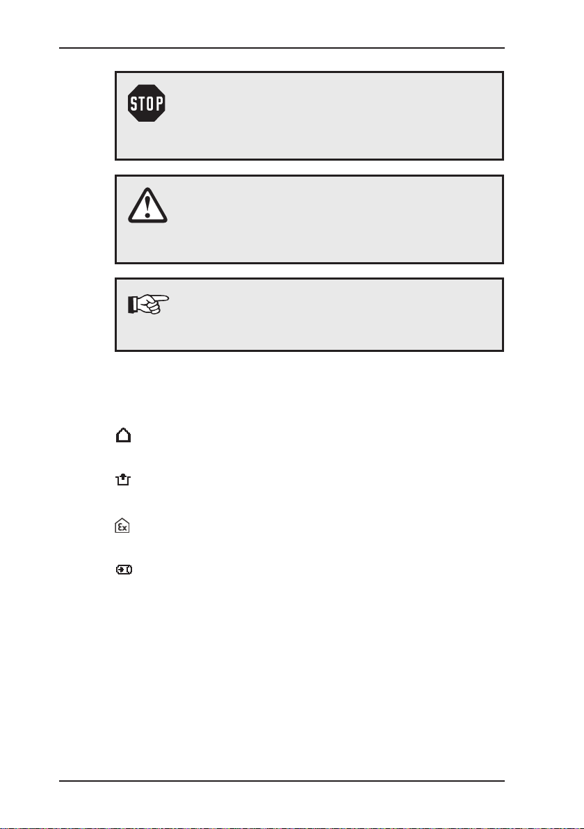
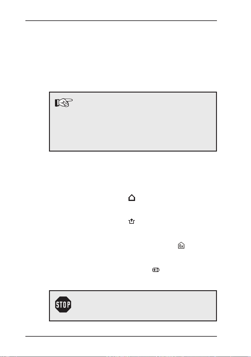
Symbols used
CAUTION! Danger of damages!
This symbol refers to important safety instructions.
Adhere strictly to these instructions to avoid material damages!
Note:
This symbol refers to information and useful tips which
are exceeding the basic operating procedures.
CAUTION! Danger of injuries!
This symbol refers to important safety instructions.
Adhere strictly to these instructions to avoid injuries!
Symbols for the applications:
House
Enclosed spaces
Warning %LEL
Measuring vol%
Page 7

Contents Page
1 General .....................................................................................1
1.1 Warranty ....................................................................................1
1.2 Purpose .....................................................................................2
1.3 Intended use .............................................................................2
1.4 General safety information ........................................................3
2 Features ...................................................................................5
2.1 Visual signals and audible signals ............................................5
2.2 Measurement principles ............................................................6
2.3 Explosion protection .................................................................. 7
3 Operation .................................................................................9
3.1 General information on operation .............................................. 9
3.1.1 Operator guidance .................................................................9
3.1.2 Operating modes ..................................................................10
3.2 Measuring mode ..................................................................... 11
3.2.1 User menu ............................................................................14
3.2.2 Setting the zero point ...........................................................15
3.2.3 House application .................................................................16
3.2.4 Enclosed spaces application ................................................ 18
3.2.5 Warning %LEL application ...................................................20
3.2.6 Measuring VOL% application ............................................... 23
3.2.7 Function control ....................................................................25
3.2.8 Changing gas types .............................................................26
3.3 Advanced settings ................................................................... 27
3.3.1 Access ..................................................................................27
3.3.2 Menu structure .....................................................................29
3.3.3 Procedure ............................................................................. 30
3.3.4 Info menu .............................................................................32
3.3.4.1 Adjustment menu .............................................................. 32
3.3.4.2 System menu .................................................................... 33
3.3.4.3 Hardware menu.................................................................38
3.3.4.4 Memory menu ................................................................... 41
3.4 Connecting accessory devices ................................................ 42
I
Page 8

Contents Page
4 Charging and battery operation ........................................... 43
4.1 General information on charging and battery operation .......... 43
4.1.1 Suitable types of rechargeable and disposable batteries .....43
4.1.1.1 Devices with serial numbers 060 0X and 061 0X..............43
4.1.1.2 Devices with serial numbers 060 1X and 061 1X..............44
4.1.2 Setting the rechargeable / disposable battery type .............. 45
4.2 Battery alarm ........................................................................... 45
4.3 Operation with nickel metal hydride rechargeable batteries
(NiMH) .....................................................................................46
4.4 Operation with alkaline non-rechargeable batteries ................ 48
5 Maintenance ..........................................................................49
5.1 Function control ....................................................................... 49
5.2 Testing indication accuracy with test gas ................................50
5.3 Adjustment ..............................................................................52
5.3.1 ppm range ............................................................................ 53
5.3.2 LEL range and % vol. range .................................................54
5.3.3 Conrming adjustment .........................................................55
5.4 Servicing .................................................................................55
5.5 Pump .......................................................................................56
5.5.1 Function control of pump ......................................................56
5.5.2 Changing the pump lter ...................................................... 57
5.5.3 Changing the sensor lter ....................................................57
6 Faults ......................................................................................58
7 Technical data........................................................................59
7.1 Features ..................................................................................59
7.2 Alarm thresholds .....................................................................60
7.2.1 Alarm thresholds for gas type methane CH4 ....................... 60
7.2.2 Setting ranges of alarm thresholds for different gas types ... 62
7.3 Response times ......................................................................63
7.4 Sensors ...................................................................................64
7.5 Ranges of use .........................................................................65
7.6 Pump capacity ......................................................................... 65
7.7 Power supply ........................................................................... 65
7.8 Dimensions and weight ...........................................................65
7.9 Technical information ..............................................................66
7.10 Advice on disposal ..................................................................68
II
Page 9

Contents Page
8 Available models and accessories ......................................69
8.1 Available models .....................................................................69
8.2 Accessories ............................................................................. 70
Appendix
Gas types
Setting ranges for test gases
Test certicates
..............................................................................................75
..............................................................................................75
................................................................. 79
......................................................................................80
EU declaration of Conformity.................................................................81
Entering a user name
............................................................................84
List of abbreviations...............................................................................86
......................................................................................................87
Index
III
Page 10

1 General
1.1 Warranty
The following instructions must be complied with in order for any
warranty to be applicable regarding functionality and safe operation of this equipment.
Hermann Sewerin GmbH cannot be held responsible for any dam-
ages resulting from non-compliance with these instructions. The
warranty and liability provisions of the terms of sale and delivery
of Hermann Sewerin GmbH are not affected by the information
given below.
z This product must only be operated after the relevant operating
instructions have been read and understood.
z This product may only be operated by qualied profession-
als who are familiar with the legal requirements (Germany:
DVGW).
z This product must only be used for its intended purpose.
z This product is only suitable for use in industrial and commer-
cial applications.
z Repairs must only be carried out by a specialist technician or
by other suitably trained personnel.
z Changes or modications to this product must not be carried
out without approval from Hermann Sewerin GmbH. The manufacturer cannot be held responsible for damages if unapproved
modications have been made.
z Only accessories supplied by Hermann Sewerin GmbH may
be used with this product.
z All repairs must be carried out using replacement parts that
have been approved by Hermann Sewerin GmbH.
z Only approved battery types may be used, otherwise the device
will not be explosion-proof.
z The manufacturer reserves the right to make technical modi-
cations in the course of further development.
1 General
Generally applicable safety and accident-prevention regulations
must be complied with, in addition to the information provided in
this manual.
1
Page 11
1 General
1.2 Purpose
The EX-TEC
tection and measurement of gas concentrations. Equipped with
three sensors, it can be used for the ppm range, the % vol. range
and the LEL range.
The EX-TEC PM 4 is available as a diffusion device (without a
pump) or pump device (with an integrated pump).
Note:
These operating instructions describe the functions of rmware version 2.XXX. The manufac-
turer reserves the right to make technical changes.
The information provided here refers to a fully
equipped EX-TEC PM 4, including pump (pump
device). It also applies for diffusion devices.
1.3 Intended use
According to DVGW Note G 465-4 the device can be used for
the following purposes:
z Testing in houses/buildings ,
e.g. measuring minute gas concentrations in buildings and
locating the origin of the gas
z Testing in enclosed spaces ,
e.g. measuring the gas concentration in enclosed spaces or
shafts with an increased potential of gas dispersal
z Warning against explosive gas concentrations ,
e.g. for monitoring work areas whilst carrying out work to gas
pipes or gas systems
z Measurement of gas concentrations ,
e.g. when decommissioning gas systems
PM 4 is an electronic handheld device for the de-
WARNING!
The EX-TEC
PM 4 is not suitable for the location or
analysis of leaks in underground pressure lines.
2
Page 12

1.4 General safety information
z The EX-TEC PM 4 has been tested to ensure that it is explosion-
proof in accordance with European standards (CENELEC).
z The functional safety of the EX-TEC PM 4 has been tested
in the LEL range, Warning (%LEL) application, for gas types
methane (CH4) and propane (C3H8).
z Use only original SEWERIN accessories with the EX-TEC PM 4.
For Flex handheld probe HG4 and Flex probe HG4, use
only SEWERIN-approved lters with activated carbon.
Otherwise, the functional safety of the EX-TEC PM 4 is not
guaranteed.
z Always open the battery compartment of the EX-TEC PM 4 and
recharge the batteries outside the potentially explosive area.
z Always use the test gases in well ventilated areas.
z Always operate the pump device model of the EX-TEC PM 4
with the pump switched on.
z Always carry out a function control (see Section 5.1) after the
EX-TEC PM 4 has suffered an impact (for example, if dropped
accidentally). Readjust the zero point if necessary (see Section 5.3).
z The EX-TEC PM 4 complies with the limits of the EMC Direc-
tive. Always observe the information in the manuals of (mobile)
radio equipment when using the device close to (mobile) radio
equipment.
z Use the EX-TEC PM 4 with the following gases only:
– Methane (CH4)
– Propane (C3H8)
– Butane (C4H10)
– Hexane (C6H14)
– Nonane (C9H20)
– Kerosene (JFUEL)
– Hydrogen (H2)
– Acetylene (C2H2)
1 General
3
Page 13

1 General
WARNING!
Follow the advice regarding explosion protection
(see Section 2.3).
z When the Warning %LEL application is in use, a brief audi-
ble signal emitted every 5 seconds indicates that the device
is working properly. If no operating signal sounds, there is no
guarantee that the gas concentration is being monitored. You
must leave the danger zone immediately.
4
Page 14
2 Features
The EX-TEC PM 4 is available in two models (see Section 8.1):
z Diffusion device: basic device without a pump
z Pump device: basic device with an integrated pump
(designation on back of device: P)
The
EX-TEC PM 4 is suitable for the following applications:
– House
– Enclosed spaces
– Warning %LEL
– Measuring vol%
2.1 Visual signals and audible signals
The device features two signalling mechanisms:
z Red alarm light on top of the device
z Buzzer on the front of the device
2 Features
Note:
These signalling mechanisms cannot be switched
off.
An audible signal is emitted each time a key is pressed:
z Very long signal On error message
z Long signal When switching device off,
When changing menus
z Short signal When switching device on,
When conrming a selection,
When navigating within a menu
5
Page 15

2 Features
2.2 Measurement principles
The device features three sensors:
Semiconductor sensor
Measuring range
Application House
Catalytic combustion sensor
Measuring range 0 to 100 % LEL
Application
Thermal conductivity sensor
Measuring range 0 to 100 % vol.
Application
0 to 10,000 ppm
Enclosed spaces
Warning %LEL
Measuring vol%
House
Enclosed spaces
6
Page 16

2.3 Explosion protection
The
EX-TEC PM 4 features the following explosion-protection
classications:
II2G Ex d e ib IIB T4 Gb
Basic device without leather bag for:
II2G Ex d e ib IIC T4 Gb
Basic device with leather bag for:
2 Features
– Methane CH
– Propane C3H
– Butane C4H
– Hexane C6H
– Nonane C9H
4
8
10
14
20
– Kerosene (JFUEL)
– Hydrogen
– Acetylene (C2H2)
– Methane CH
– Propane C3H
– Butane C4H
– Hexane C6H
– Nonane C9H
4
8
10
14
20
– Kerosene (JFUEL)
The respective test certicates are provided in the appendix.
7
Page 17

2 Features
WARNING!
It is essential to observe the following points to en-
sure that the device is explosion-proof:
– Always open the battery compartment outside the
potentially explosive area.
– Always recharge the batteries outside the poten-
tially explosive area.
– Use only approved battery types.
– Use of the leather bag is mandatory to achieve
class IIC for gas types hydrogen (H2) und acetylene (C2H2).
8
Page 18

3 Operation
3.1 General information on operation
3.1.1 Operator guidance
There are two ways to operate the
– Operator guidance by application
– Operator guidance by sensor
These operating instructions are based on operator guidance by
application in accordance with DVGW Note G 465-4:
– Testing in houses/buildings (House application)
– Testing in enclosed spaces (Enclosed spaces application)
– Warning against explosive gas concentrations
(Warning %LEL application)
– Measurement of gas concentrations
(Measuring VOL% application)
3 Operation
EX-TEC PM 4:
Note:
The factory default operator guidance setting for the
device is Application. This can be changed to Sen-
sor in the advanced settings (see Section 3.3.4.2).
9
Page 19

3 Operation
3.1.2 Operating modes
The device is operated in two modes:
z Measuring mode (Section 3.2)
Measurements are taken in measuring mode. The zero point
can be set, the application can be changed and the gas type
can be selected via the user menu.
z Advanced settings (Section 3.3)
The advanced settings allow you to change specications for
the measurements as well as other device settings (e.g. adjustment, system, hardware, etc.). You cannot perform measurements in the advanced settings.
10
Page 20
3.2 Measuring mode
The device is switched off.
Note:
Always switch the device on in fresh air.
z Press the key for approximately 3 seconds.
The device switches on. At this point, the two signalling mechanisms are always tested.
WARNING!
Do not use the device if you do not see the visual
signal and hear the audible signal briey when
switching on the device.
The LCD switches on. The pump runs with constant output
power.
The two start screens shown below are displayed:
3 Operation
Start screen
Display:
– Device type (EX TEC PM4)
– Firmware version (V2.000)
– Integrated sensors
(PPM LEL VOL)
Date/time
Display:
– Date (27/11/2008)
– Time (12:37)
– User data
11
Page 21
3 Operation
Enclosed spaces
The device accesses the preset application. Two additional
screens are displayed automatically.
Display screens for the different applications:
Note:
The start-up application can be changed in the advanced settings (see Section 3.3.4.3). The factory
default setting for the device is the
application.
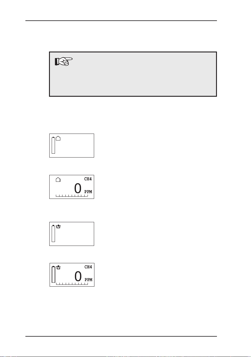
z House
House
acoustic/LED
1 PPM
CH4
Warning %LEL
Measuring range
Name of application with specication of associated signals and
measurement unit
Measurement data
Measurement data display
12
z Enclosed spaces
CH4
LED
1 PPM
Measuring range
Name of application with specication of associated signals and
measurement unit
Measurement data
Measurement data display
Page 22
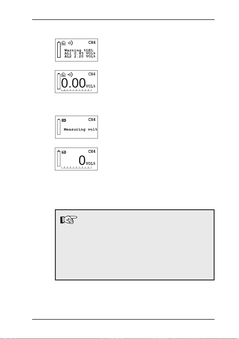
z Warning %LEL
z Measuring VOL%
3 Operation
Measuring range
Name of application with specication of measurement unit
Measurement data
Measurement data display
Measuring range
Name of application with specication of measurement unit
Measurement data
Measurement data display
You cannot input any information until the device has stopped
cycling through the displays. The device is not in measuring mode
until the Measurement data screen is displayed.
Note:
When the device is switched on, the sensors must
warm up. The duration of the warm-up time depends
on the sensor type.
After switching on the device, changing the measuring range or setting the zero point, you may notice
the reading ashing on the display. The device is
only ready for use when the displayed reading stops
ashing.
13
Page 23
3 Operation
zero point
type of gas
3.2.1 User menu
Measuring mode comprises the following functional scope:
– Zero point correction
– Application selection
– Conrmation of function control
– Gas type (optional)
The functions in the user menu are described in Sections 3.2.2
to 3.2.8.
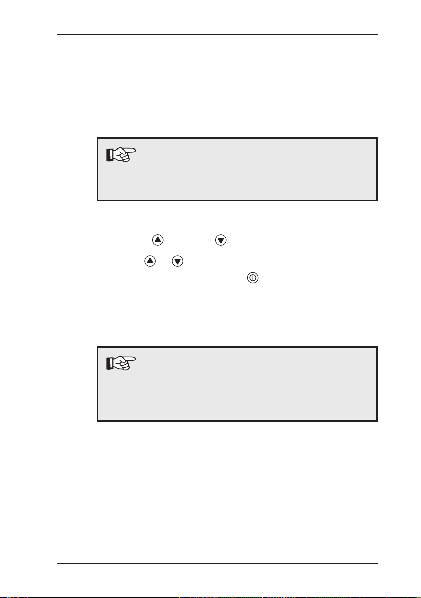
To select functions, you must rst access the user menu:
z Press the key or the key for approximately 2 seconds.
The user menu is displayed:
House
Enclosed spaces
Warning %LEL
Measuring vol%
inspection ok
14
To move between menu items:
z Navigate up and down in the menu by briey pressing the
or key.
z Conrm your selection by briey pressing the key.
If the selection is not conrmed, the display reverts back to measuring mode after approximately 10 seconds.
Page 24
3.2.2 Setting the zero point
In general, the device sets the zero point automatically. However,
in certain cases, values other than zero may be displayed when
the device is switched on. This indicates a deviating zero point,
meaning that the device must be adjusted manually to environmental conditions.
Note:
The zero point must be set separately for each application. The zero point setting must be carried out
with fresh air.
To set the device to zero:
z Press the key or the key for approximately 2 seconds.
z Use the or key to select the Zero point menu item.
z Conrm your selection with the key.
The device returns to measuring mode.
The displayed value is zero (0).
3 Operation
Note:
If the displayed value is not zero (0), this means that
the zero point of the device could not be set because
the measured value was outside the specied limits
(see appendix).
15
Page 25

3 Operation
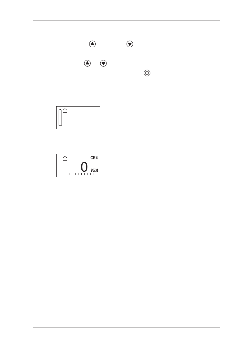
3.2.3 House application
The House application is used to measure minute gas concentra-
tions in buildings and to locate the origin of the gas.
Measurement unit:
Measuring range:
Semiconductor 0 to 10,000 ppm
Thermal conductivity 1 to 100 % vol.
ppm (parts per million)
% vol.
Signals (methane CH
):
4
Audible Intermittent tone
increasing from
0 to 22,000 ppm (AL2)
Continuous tone
2.2 % vol. and greater (AL2)
Visual Flashing
increasing from 4,400 ppm
(AL1) to 22,000 ppm (AL2)
Continuously On
2.2 % vol. and greater (AL2)
16
Page 26
3 Operation
Procedure:
z Press the key or the key for approximately 2 seconds
to access the user menu.
z Use the or key to select the House menu item.
z Conrm your selection with the key.
Following conrmation, the start screen for the House application
is displayed initially.
House
acoustic/LED
CH4
1 PPM
Measuring range
Then the device returns to measuring mode. The measured values are displayed.
Measurement data
In number format: e.g. 0 ppm
As a trend bar divided into
4 parts ranging from
0 ppm to 10,000 ppm: 0 ppm – 10 ppm
10 ppm – 100 ppm
100 ppm – 1,000 ppm
1,000 ppm – 10,000 ppm
A specic signal is emitted based on the reading, gas type and
preset value.
17
Page 27

3 Operation
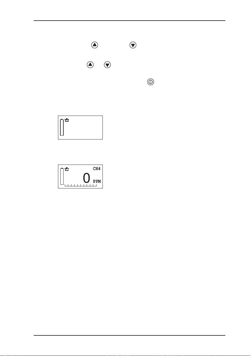
3.2.4 Enclosed spaces application
The Enclosed spaces application is used to measure gas con-
centrations in enclosed spaces where there is increased potential
of gas dispersal.
Measurement unit:
Measuring range:
Semiconductor 0 to 10,000 ppm
Thermal conductivity 0.1 to 100 % vol.
ppm (parts per million)
% vol.
Signals (methane CH
):
4
Audible No signal
Visual Flashing
increasing from 4,400 ppm
(AL1) to 22,000 ppm (AL2)
Continuously On
2.2 % vol. and greater (AL2)
18
Page 28
3 Operation
Enclosed spaces
Procedure:
z Press the key or the key for approximately 2 seconds
to access the user menu.
z Use the or key to select the Enclosed spaces menu
item.
z Conrm your selection with the key.
Following conrmation, the start screen for the Enclosed spaces
application is displayed initially.
CH4
LED
1 PPM
Measuring range
Then the device returns to measuring mode. The measured values are displayed.
Measurement data
In number format: e.g. 0 ppm
As a trend bar divided into
6 parts ranging from
0 ppm to 100 % vol.: 0 ppm – 10 ppm
10 ppm – 100 ppm
100 ppm – 1,000 ppm (0.1 % vol.)
0.1 % vol. - 1 % vol.
1 % vol. - 10 % vol.
10 % vol. - 100 % vol.
19
Page 29
3 Operation
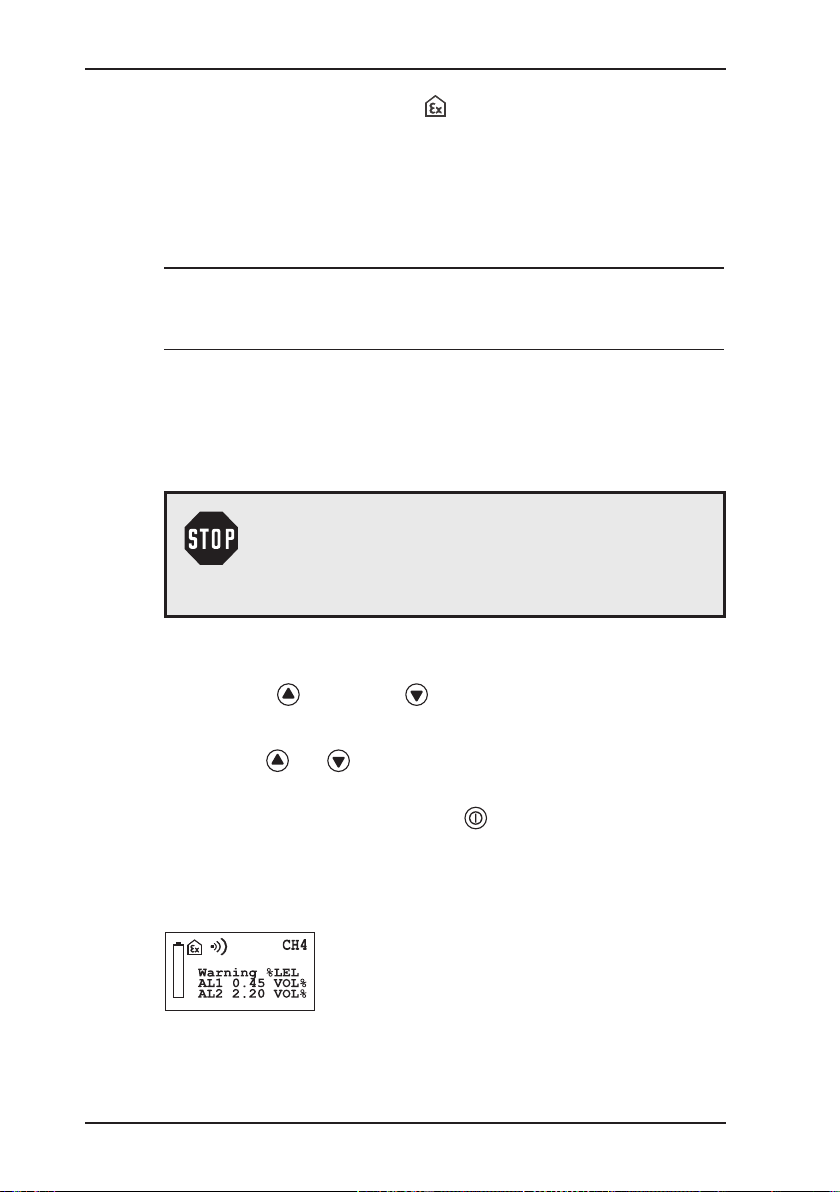
3.2.5 Warning %LEL application
The Warning %LEL application is used to test working environ-
ments where explosion is possible, e.g. working on gas pipes or
gas systems.
Measurement unit:
Measuring range:
Catalytic combustion 1 % LEL to 100 % LEL
In the
Warning %LEL application, a brief audible signal emitted
every 5 seconds indicates that the device is working properly.
WARNING!
If no operating signal sounds, there is no guarantee
that the gas concentration is being monitored. You
must leave the danger zone immediately.
% LEL
20
Procedure:
z Press the key or the key for approximately 2 seconds
to access the user menu.
z Use the or key to select the Warning %LEL menu
item.
z Conrm your selection with the key.
Following conrmation, the start screen for the Warning %LEL
application is displayed initially.
Measuring range
Page 30

3 Operation
Then the device returns to measuring mode. The measured values are displayed.
Measurement data
In number format: e.g. 0.00 % vol.
As a trend bar divided into 10 parts ranging from 0 % LEL to
100 % LEL in increments of 10 %.
For the Warning %LEL application, the EX-TEC PM 4 features
three alarm thresholds.
Alarm thresholds
z Alarm threshold 1 (AL1 – pre-alarm):
– When this alarm threshold is exceeded, an audible alarm and
a visual alarm are triggered and AL1 appears on the display.
– The audible alarm (2-Hz intermittent tone) is distinctly differ-
ent from the operating signal.
– The audible alarm can be acknowledged by pressing the
key. The visual alarm remains active.
– When the level drops below this alarm threshold concentra-
tion, the alarms switch off.
z Alarm threshold 2 (AL2 – main alarm):
– When this alarm threshold is exceeded, an audible alarm
and a visual alarm are triggered and AL2 appears on the
display.
– The audible alarm (5-Hz rapid intermittent tone) is distinctly
different from the operating signal.
– The AL2 alarm cannot be acknowledged.
– When the level drops below this alarm threshold concentra-
tion, the alarm can be acknowledged.
21
Page 31

3 Operation
z Alarm threshold 3 (AL3 – continuous alarm and end of meas-
uring range):
– When this alarm threshold is exceeded, a continuous audible
alarm and a continuous visual alarm are triggered and AL3
ashes on the display.
– The continuous tone is distinctly different from the operat-
ing signal.
– The AL3 alarm cannot be acknowledged.
– There are two ways to terminate the AL3 alarm:
– By switching to the Measuring VOL% application
– By switching off the device
The alarm thresholds can be adjusted in the System menu
(see Section 3.3.4.2).
The setting ranges of the alarm thresholds are specied under
Technical data (see Section 7.2).
22
Page 32

3.2.6 Measuring VOL% application
The Measuring VOL% application is used to demonstrate gas
purity or the absence of gas in gas pipes.
WARNING!
The
Measuring VOL% application is not suitable
for use in hazardous areas. It does not comprise
an alarm mechanism.
Measurement unit:
Measuring range:
Thermal conductivity
Signals (methane CH4):
Audible Intermittent tone
3 Operation
% vol.
1 % vol. to 100 % vol.
At 100 % vol. (AL5)
Visual Flashing
At 100 % vol. (AL5)
Procedure:
z Press the key or the key for approximately 2 seconds
to access the user menu.
z Use the or key to select the Measuring VOL% menu
item.
z Conrm your selection with the key.
23
Page 33

3 Operation
Following conrmation, the start screen for the Measuring VOL%
application is displayed initially.
Then the device returns to measuring mode. The measured values are displayed.
In number format: e.g. 0 % vol.
As a trend bar divided into 10 parts from 0 % vol. to 100 % vol.
in increments of 10 %.
Measuring range
Measurement data
24
Page 34

3.2.7 Function control
Before starting work and when resuming work after an interruption,
you must carry out a function control. The scope of the function
control is described in Section 5.1.
Conrm the successful completion of the control on the device
as follows:
z Press the key or the key for approximately 2 seconds.
z Use the or key to select the Inspection OK menu
item.
z Conrm your selection with the key.
The function control is saved. The device returns to the application.
3 Operation
25
Page 35

3 Operation
3.2.8 Changing gas types
Note:
Always change the gas type in fresh air.
Only calibrated gas types can be selected in the
user menu.
The factory default setting for the device is
methane CH4 (or a special gas you have ordered).
z Press the key or the key for approximately 2 seconds.
z Use the or key to select the Gas type menu item.
z Conrm your selection with the key.
z Use the or key to select the required gas type.
z Conrm your selection with the key.
After you have selected the gas type, the device returns to the
Warning %LEL application.
To perform measurements for another application, follow the instructions provided to select this application.
26
Note:
Gas type changes made in the user menu are only
temporary. The preset gas will be selected again the
next time the device is switched off and back on. To
permanently change the gas type, use the advanced
settings (see Section 3.3.4.3).
Page 36

3.3 Advanced settings
PIN 0001
Settings for the following areas of the device can be made in the
advanced settings:
z Adjustment
z System
z Hardware
z Memory
You cannot perform measurements in the advanced settings.
3.3.1 Access
There are two ways to access the Advanced settings area:
The device is switched off:
z Simultaneously press the , and keys for approximately
2 seconds.
The device is in measuring mode:
z Simultaneously press the and keys for approximately
2 seconds.
The following display appears:
3 Operation
Access is protected by a PIN code. The default setting is always
PIN code 0001.
The device can be set so that only authorised users have access
to the Info menu.
It is advisable to reset the PIN code after starting the device for
the rst time.
27
Page 37

3 Operation
Enter the PIN code from left to right. The active digit is always
displayed with a black background:
If the PIN code has been entered correctly, the Info menu will
appear once the last digit has been conrmed:
Note:
If the PIN code is set to 0000, you will not be
asked to enter the PIN code. The advanced
settings can then be accessed by anyone.
If you cannot access the Advanced settings area,
for example, if you have lost the PIN code, you must
contact SEWERIN Service.
z Use the or key to select the rst digit.
z Conrm your selection with the key. The device jumps to
the second digit.
z Enter all digits of your code in sequence, conrming each entry.
adjustment
system
hardware
memory
exit
28
Otherwise the device will return to measuring mode.
Page 38

3.3.2 Menu structure
Menu level 1 Menu level 2
Measuring mode Info V2.000
PIN code adjustment 0 PPM
Measuring mode
3 Operation
10000 PPM
0 %LEL
50 %LEL
100 VOL%
inspection ok
exit
system date / time
date format
INS interval
INS block
PPM signal
PIN code
AL1 alarm
AL2 alarm
AL4 alarm
AL5 alarm
test gas PPM
test gas %LEL
unit %LEL
unit VOL%
user name
Operator guid.
language
exit
hardware battery
Accu capacity
back light
contrast
sensors
type of gas
autostart
level PPM
pump
LCD test
reset
exit
memory clear
interval
exit
exit
29
Page 39

3 Operation
3.3.3 Procedure
The advanced settings are divided into three menu levels.
z The rst two menu levels are used to organise and subdivide
the settings options.
z A concrete selection or entry is made in the third menu level.
The name of the current menu
(e.g. Info) is always shown at
the top left of the display.
The items available for selection
are displayed in the frame below
(e.g. Adjustment, System).
The Info menu (menu level 1)
also includes the rmware ver-
sion (e.g. V2.000).
30
Use the
and keys to navigate within a menu.
Press the key to conrm the selected menu item.
Menu level 1 and 2
The Exit menu item always appears at the end of a menu.
When you select this item, the display reverts back to the previ-
ous menu.
Exception: In menu level 1 the device returns to measuring mode.
Page 40

3 Operation
Menu level 3
Menu level 3 is used to select settings or enter values:
z Selecting settings
Use the
and keys to navigate within a selection.
Press the key to conrm the selected setting.
When you have conrmed your selection, the display reverts
to the previous menu.
z Entering values
The congurable position is always displayed with a black
background.
Use the
or key to increase or decrease the value.
Press the key to conrm the selected value.
Note:
Always conrm each value. Values can only be
specied going forward. Once you have started
entering values, it is not possible to interrupt this
process.
When you have conrmed the last value, the display reverts to
the previous menu.
31
Page 41

3 Operation
3.3.4 Info menu
The Info menu is located at the top of the Advanced settings:
adjustment
system
hardware
memory
exit
Note:
When you select Exit from the Info menu, the de-
vice returns to measuring mode.
3.3.4.1 Adjustment menu
The Adjustment menu is used to set the sensors.
adjustment 0 PPM
10000 PPM
0 %LEL
50 %LEL
100 VOL%
inspection ok
exit
32
Note:
Refer to Section 5.3 for detailed information on carrying out an adjustment.
Page 42

3.3.4.2 System menu
27.11.2008 12:37
DD.MM.YYYY
YYYY-MM-DD
Weeks 00
General information and specications for operation, inspection
and alarms are set on the System menu.
system date/time
3 Operation
date format
INS interval
INS block
PPM signal
PIN code
AL1 alarm
AL2 alarm
AL4 alarm
AL5 alarm
test gas PPM
test gas %LEL
unit %LEL
unit VOL%
user name
Operator guid.
language
exit
Date/time
Used to enter the date and time.
This is important for documenting the measurements.
Date format
There are two formats available
for the date.
INS interval
The inspection interval setting
reminds you to inspect/adjust the
device regularly.
33
Page 43

3 Operation
Yes
No
acoustic /LED
No
%LEL 10
%LEL 20
A 0.50 Vol%
acoustic
LED
INS block
When the inspection block is
enabled, an inspection must be
performed on the next due date.
The device cannot be used in
measuring mode until the inspection has been carried out and
conrmed.
PPM signal
Used to switch visual/audible
signals on and off in the ppm
range.
PIN 0000
PIN code
Used to enter your PIN code
enabling access to the advanced
settings.
AL1 alarm
First modifiable alarm thresh-
old: e.g. 10 % LEL for Warning %LEL application
AL2 alarm
Second modiable alarm threshold: e.g. 20 % LEL for Warn-
ing %LEL application
AL4 alarm
No function assigned for operator guidance by application
For operator guidance by sen-
sor, this is the permanently
assigned alarm threshold for
automatic mode.
.
34
Page 44

3 Operation
VOL% 100
1.00 Vol%
2.20 Vol%
%LEL 50
%UEG
tf.%
AL5 alarm
Permanently assigned alarm
threshold for the Measur-
ing VOL% application.
Indicates the end of the measuring range.
Test gas PPM
Used to set the test gas concentration for the ppm range
based on the gas type.
The setting range is provided in
the appendix.
Test gas %LEL
Used to set the test gas con-
centration for the LEL range
based on the gas type.
The setting range is provided in
the appendix.
%LEL
%LIE
%DMV
%DGW
%SEM
%DGE
ARH%
VOL%
%VOL
%GAZ
%OBJ
Unit %LEL
Used to set individual measured
variables for the LEL range
(
Warning %LEL application).
35
Page 45

VOL%
tf.%
City Council
Leakage Delivery
Intended use
sensors
3 Operation
%VOL
%GAZ
%OBJ
Frank Smith
Unit VOL%
Used to set individual measured
variables for the VOL range
(
Measuring VOL% application).
User name
Used to enter the user name.
This is important for documenting the measurements.
The procedure and characters
that can be displayed are provided in the appendix.
Operator guidance
Used to select operator guidance
by application (House, Enclosed
spaces, Warning %LEL, Measuring VOL%) or by sensor (PPM,
LEL, VOL).
When using operator guidance
by sensor, the four applications
for measuring mode are replaced
by the following operating modes:
z GAS DETECTION
(0..10000 PPM)
z GAS WARNING
(0....100%LEL)
z GAS MEASURING
(0....100 VOL%)
z AUTOMATIC
Automatic measuring range
changeover from 0 ppm to 100 %
vol. according to gas concentration present.
36
Page 46

zero point
type of gas
Deutsch
English
Hungarian
Français
Italiano
Dansk
Cesky
Polski
Chinese
Slovenia
Kroatian
Dutch
Español
3 Operation
For operator guidance by sensor,
the user menu looks like this:
0..10000 PPM
0....100 %LEL
0....100 VOL%
automatic
inspection ok
Language
The device can be operated in
13 different languages.
37
Page 47

3 Operation
hardware battery
exit
Accu Ni-MH
Alcaline
mAh 1850
Sec 010
3.3.4.3 Hardware menu
The Hardware menu comprises settings pertaining to device
management.
Accu capacity
back light
contrast
sensors
type of gas
autostart
level PPM
pump
LCD test
reset
Battery
Used to set the battery type in
use. This is important for calculating the operating time.
38
Accu capacity
Used to enter the rechargeable
battery capacity. This is important for calculating the operating
time.
Light
Used to specify how long the
LCD will remain lit after a key is
pressed.
Page 48

0 – 100%
CH4
C2H2
PPM LEL VOL
PPM LEL
VOL
PPM VOL
PPM
LEL VOL
LEL
CAUTION!
Settings in the Sensors menu item may only be
congured by SEWERIN Service!
3 Operation
Contrast
Contrast settings to facilitate
reading of the LCD (in approximately 30 increments).
Sensors
C3H8
C4H10
C6H14
C9H20
JFUEL
H2
TGAS
Gas type
Used to permanently change the
measuring medium.
Note:
The new gas type is not activated until the device
has been adjusted (and the adjustment has been
conrmed) (see Section 5.3).
39
Page 49

3 Operation
0..10000 PPM
automatic
House
Measuring vol%
PPM 001
Yes
No
LCD test
Yes
No
Enclosed spaces
Warning %LEL
Autostart
Use to set the test type that is
activated when the device is
switched on.
For operator guidance by sensor, the autostart menu looks
like this:
0....100 %LEL
0....100 VOL%
Level PPM
Used to set the response threshold for the House and Enclosed
spaces applications, for example, to decrease the measuring
sensitivity.
40
Pump
Used to switch the pump on
and off.
WARNING!
When using a pump device, never switch the pump
off for any reason other than maintenance.
LCD test
Used to test the working condi-
tion of the LCD.
Reset
Used to reset all settings to the
factory settings.
Page 50

3.3.4.4 Memory menu
memory clear
exit
Yes
No
30 Sec
The Memory menu enables you to delete the recorded measurements, function controls and alarms. All other settings remain
unchanged.
Capacity of data memory:
3 Operation
interval
Clear
Used to clear the contents of the
memory.
Interval
The frequency with which readings are to be saved can be set
according to the table below.
Interval [s] Typ. capacity [h]
1 7
2 15
5 39
10 78
20 156
30 234
60 470
Note:
Data stored in memory can be retrieved by means
of a docking station with an interface.
41
Page 51

3 Operation
3.4 Connecting accessory devices
The following accessory devices can be tted to the sensor head:
z Probes
For detection and measurement in hard-to-reach places.
Probes are tted using two knurled thumb screws.
z Test head
For adjusting the device using a test set.
Note:
Certain probe types can only be used with devices
having an integrated pump.
42
Page 52

4 Charging and battery operation
4 Charging and battery operation
4.1 General information on charging and battery operation
WARNING!
The device must not be used with leaking disposable / rechargeable batteries. Replace disposable / re-
chargeable batteries in a timely manner. Clean the battery compartment (and, if necessary, the device) before
inserting the new disposable / rechargeable batteries.
4.1.1 Suitable types of rechargeable and disposable batteries
WARNING!
Use only approved rechargeable or disposable
battery types; otherwise, the device will not be
explosion-proof!
Compliance with indications based on the serial
number of your device is strictly mandatory!
4.1.1.1 Devices with serial numbers 060 0X and 061 0X
Only the following rechargeable batteries and disposable batteries
approved by the Physikalisch-Technische Bundesanstalt (German national metrology institute) or the TÜV (German technical
inspection association) are permitted for use in these devices
(
II 2 G EEx ib d IIB T3):
Manufacturer Designation
NiMH rechargeable cell batteries
Panasonic: HHR-150-AA Flat Top
Sanyo: AA HR3U
Varta: VH 1600AA, 55117 201 052
Alkaline disposable batteries
Varta: No. 4006, LR6-AA-AM3
Varta / Electric Power: No. 8006, LR6-AA-AM3
Duracell: MN 1500, size AA
43
Page 53

4 Charging and battery operation
4.1.1.2 Devices with serial numbers 060 1X and 061 1X
WARNING!
To ensure that the device remains explosion-proof
as per Directive 94/9/EC, only the following disposable / rechargeable batteries may be used:
– Batteries supplied by SEWERIN
– Batteries other than those supplied by
SEWERIN, provided they comply with standard
EN 60079-7:2003 (in particular Section 5.7.2.1.17;
explanation below)
The battery types used in a battery compartment
must always be identical in terms of sort (dispos-
able / rechargeable), capacity and manufacturer.
Disposable battery requirements
z Type: size AA
z The creepage distance and air gap between the poles must not
be less than 0.5 mm (EN 60079-7:2003; Section 5.7.2.1.17).
z Alkaline disposable batteries must comply with EN 60086-1
type LR6.
44
Rechargeable battery requirements
z Type: size AA
z The creepage distance and air gap between the poles must not
be less than 0.5 mm (EN 60079-7:2003; Section 5.7.2.1.17).
z Rechargeable batteries must meet the requirements of
IEC 61951-2 type HR6 and comply with the temperature
range.
CAUTION!
A device operated with disposable alkaline batteries
cannot be charged. A note will appear in the display
accordingly.
The device comes supplied with nickel metal hydride rechargeable batteries. The corresponding settings are stored.
Page 54

4 Charging and battery operation
4.1.2 Setting the rechargeable / disposable battery type
To ensure that the charging time and remaining battery life are
properly displayed, you must specify the following in the advanced
settings:
z Rechargeable battery type (Info menu – Hardware – Battery)
z Capacity of rechargeable types in use (Info menu – Hardware –
Accu capacity)
The device comes supplied with nickel metal hydride rechargeable batteries. The corresponding settings are stored.
This device can be operated using:
z Nickel metal hydride rechargeable batteries (see Section 4.3)
z Alkaline non-rechargeable batteries (see Section 4.4)
4.2 Battery alarm
When the power supply becomes
low, a battery alarm is emitted:
– The battery symbol appears
on the LCD.
– The operating signal sounds at
double the normal frequency.
When the battery alarm is triggered, an operating time of at least
15 minutes remains. After this, the device must be recharged.
45
Page 55

4 Charging and battery operation
4.3 Operation with nickel metal hydride rechargeable batteries (NiMH)
The docking station HG4 is
required for charging.
The docking station can be used
in the workshop or in the service
vehicle.
CAUTION!
Compliance with the following guidelines is essential
to ensure trouble-free operation:
z The docking station must not be directly connected
to a 24-V on-board power supply in the vehicle.
The voltage is too high for the charging process.
z The rechargeable battery should be charged at
approximately room temperature.
z Short operating times and long periods out of use
can reduce the available capacity of the rechargeable battery (memory effect).
46
Ways to connect the docking station to the power supply:
z AC/DC adapter for 100 – 240 V~
z Vehicle cable mounting for 12 V=
z Vehicle cable mobile for 12 V=
z Vehicle cable mounting for 24 V=
Note:
Up to three docking stations can be operated on an
AC/DC adapter for 100 – 240 V~. For four or more
docking stations, the charging voltage is too low. In
this case, an error message is displayed.
Page 56

4 Charging and battery operation
Charging:
z Place the device (switched off) into the docking station.
The time required for complete charging is displayed.
Once the rechargeable batteries have been fully charged, the
device automatically switches to charge maintenance mode.
It can remain in the docking station until the next time it is used.
After at least 12 hours of charging time (depending on the capacity of the rechargeable battery), the device has an available
operating time of at least 8 hours.
Note:
If the device is switched off and stored outside the docking station, the nickel metal hydride rechargeable battery will begin to self-
discharge. The rechargeable batteries will
lose their charge after 30 days at the latest.
To preserve the capacity of the rechargeable batter-
ies, discharge the device completely and recharge it
again fully on a regular basis (e.g. once a month).
Discharging:
z Place the device (switched on) into the docking station.
z The rechargeable batteries will be fully discharged. Once the
device has been discharged, it will automatically switch to
charging mode.
A full discharging and recharging cycle takes approximately
20 hours (8 hours discharging + 12 hours recharging). The
duration depends on the capacity of the accumulator used.
Note:
When you switch from alkaline disposable batteries to nickel metal hydride rechargeable batteries,
the operating hours indication on the display is incorrect. Switch the device on and place it into the
docking station to allow it to discharge and recharge
automatically. The operating hours will then be displayed correctly.
47
Page 57

4 Charging and battery operation
4.4 Operation with alkaline non-rechargeable batteries
CAUTION!
A device operated with alkaline disposable batteries
cannot be charged in the docking station. A message
to this effect appears on the display if the device is
placed into the docking station.
When equipped with new disposable alkaline batteries, the
EX-TEC PM 4 has an available operating time of at least 12 hours
(depending on the capacity of the accumulator used).
Follow the steps below to change the batteries:
z Using the supplied screwdriver, unscrew the bottom two screws
on the back of the device.
z Open the battery compartment.
z Insert the new battery cells in the direction indicated.
z Close the battery compartment.
z Re-tighten the bottom two screws on the back of the device.
48
Note:
If it takes longer than 120 seconds to change the
batteries, the date and time will have to be reset
the next time you switch the device on. All the other
data will be saved.
Page 58

5 Maintenance
In accordance with legal regulations, device maintenance com-
prises the following elements:
z Function control
z Indication accuracy test
z Adjustment
z Servicing
Note:
As specied in EN 60079-29-2 / BGI T 023, portable gas warning devices must be tested by the
user immediately prior to each use. The test scope
comprises the function control and the indication
accuracy test using test gas.
5.1 Function control
The function control must be carried out by the user before commencing work.
The following elements must be tested:
z External condition of device incl. probe systems
z Function of controls
z Battery charge status
z Airow passages
z Pump function (Section 5.5)
z Zero point when switching device on (fresh air)
z Accessories
When switching the device on, if the zero point deviation is greater
than is permissible for the respective gas type (see appendix: Gas
types), you must readjust the zero point (see Section 5.3).
The following must also be tested:
z Indication accuracy with test gas (Section 5.2)
5 Maintenance
49
Page 59

5 Maintenance
The frequency of the test depends on the application. For the
Warning %LEL application, it must be carried out before commencing each work session!
When the function control is complete, it can be stored in the user
menu (see Section 3.2.7).
5.2 Testing indication accuracy with test gas
The frequency of the test depends on the application.
Application When to test Legal basis
Warning %LEL Daily when com-
mencing work
House Weekly to every six
Enclosed spaces
months
EN 60079-292 / BGI T 023
DVGW G 465-4
Measuring VOL%
The indication accuracy must be tested separately for each
calibrated gas type.
All tests must be documented. The documentation must be kept
for at least one year.
50
Connections and controls on the
(shown here: SPE HG)
C
D
A Device connection
B Test gas connection
C Pressure gauge
D Release button
A
E Connecting hose
B
E
tester
Page 60

5 Maintenance
Carry out the indication accuracy test as follows:
z Insert connecting hose (E) into connection (A) and attach it to
the EX-TEC PM 4.
z Screw the test gas canister onto connection (B). Pressure
gauge (C) indicates the pressure inside the test gas canister.
z Switch on the EX-TEC PM 4.
z Wait until the EX-TEC PM 4 has nished warming up.
z Press release button (D) to release the test gas. Keep the but-
ton depressed.
z Continue to keep release button (D) depressed until the value
displayed on the EX-TEC PM 4 has stabilized. Then release
the button.
The value displayed on the
EX-TEC PM 4 must correspond
to the specified concentration of the test gas or fall with-
in the permissible tolerances (see appendix: Gas types).
If the display values fall outside the specied tolerances, the
EX-TEC PM 4 must be readjusted (see Section 5.3).
Enter the test results in the test protocol (see appendix).
51
Page 61

5 Maintenance
5.3 Adjustment
Both the zero point and the indication accuracy must be adjusted
for each of the three sensors.
The Adjustment menu is shown in Section 3.3.4.1. The overview
below shows the menu items and corresponding sensors. These
these items in menu level 2 can be accessed via the advanced
settings of the Info menu, under Adjustment.
WARNING!
The device be adjusted by specialist technicians
only. Incorrect adjustment can result in incorrect
analysis of the measurement results.
Menu item Sensor Measuring
Adjusts:
range
0 PPM Semiconductor ppm Zero point
10000 PPM Semiconductor ppm Indication
accuracy
0%LEL Catalytic
LEL Zero point
combustion
Thermal
% vol.
conductivity
50%LEL Catalytic
combustion
100 VOL% Thermal
conductivity
LEL Indication
accuracy
% vol. Indication
accuracy
Note:
Each time you select Reset from the Hardware
menu, you must subsequently carry out an adjustment.
52
Page 62

5.3.1 ppm range
5 Maintenance
CAUTION!
Atmospheric humidity can cause interference in the
semiconductor sensor. Therefore, never adjust the
device without using conditioner tted between the
device and the test set!
Tools:
z Test head HG 4
z Test set with integrated conditioner
(e.g. SPE ppm, SPE 2, SPE DUO)
OR
Test set without integrated conditioner
(e.g. SPE HG, SPE VOL, SPE Y) and
additionally a conditioner, which must
be tted between the device and the
test set
Zero point test gas: Fresh air
Indication accuracy
1.00 % vol. CH
4
test gas:
Setting the zero point
z Connect the device to the test set.
To do so, follow the steps indicated in the operating instructions
for the tester. Be sure to remember the conditioner if it is not
already included in the test set.
z Add fresh air as the test gas.
z Wait until the value on the LCD no longer ashes.
z Press the On/Off key to conrm.
Setting the indication accuracy
z Connect the device to the test set.
To do so, follow the steps indicated in the operating instructions
for the tester. Be sure to remember the conditioner if it is not
already included in the test set.
z Place the test head on the device.
53
Page 63

5 Maintenance
z Press and hold the release button on the test set until the con-
centration displayed on the device has reached a stable value.
z Press the On/Off key to conrm.
5.3.2 LEL range and % vol. range
Tools:
z Test head HG 4
z Test set (see Accessories)
Zero point test gas: Fresh air
Indication accuracy
test gas:
2.20 % vol. CH4 for 50 % LEL adjustment
100 % vol. CH4 for 100 % LEL adjustment
Setting the zero point
Tools are not required to set the zero point.
The zero points for the LEL range and the % vol. range are always
set together in one step.
z Switch on the device.
z Add fresh air as the test gas.
z Wait until the value on the LCD no longer ashes.
z Press the On/Off key to conrm.
Setting the indication accuracy
z Connect the device to the test set.
To do so, follow the steps indicated in the operating instructions for the tester.
z Place the test head on the device.
z Press and hold the release button on the test set for at least
1 minute. Do not let go of the release button until the concen-
tration displayed on the device has reached a stable value.
z Press the On/Off key to conrm.
z Remove the test head and wait until the zero point has reset
itself.
54
Page 64

5.3.3 Conrming adjustment
As part of the adjustment process, each completed test must
be stored in memory. This is done via the Inspection OK menu
item. As a result:
z The test date is saved.
z The next adjustment date is calculated based on the specied
inspection interval.
z An inspection block (if set) is triggered.
Conrm the completed adjustment on the device as follows:
z Using the or key, select the Inspection OK menu item.
z Conrm your selection with the key.
5.4 Servicing
The device must only be serviced and repaired by SEWERIN
Service or a qualied service technician/company authorised by
SEWERIN.
z Send the device to SEWERIN for repairs and for annual main-
tenance.
5 Maintenance
Note:
If there is a service agreement in place, the device can
be serviced by the mobile maintenance service.
The inspection plate on the device shows
conrmation of the last maintenance and the
next scheduled maintenance.
55
Page 65

5 Maintenance
5.5 Pump
Note:
The descriptions in this section refer only to pump
devices.
The integrated pump in pump devices accelerates the purging
of the device with fresh air. The device pump has a capacity of
approximately 10 l/h.
5.5.1 Function control of pump
The pump function in pump devices is tested by a simple leak
tightness check:
z Switch on the device in fresh air.
z Make sure the pump is switched on.
z Seal off the sensor head for approximately 10 seconds, by
holding the test cap closed, for example.
If the pump is functioning properly, a corresponding error
message will be displayed.
56
Press any key to acknowledge the error message.
If the error message does not appear, the pump may be faulty.
Have the device tested by SEWERIN Service.
Page 66

5.5.2 Changing the pump lter
CAUTION!
Always switch off the device before changing the
lter.
z Unscrew and remove the sensor cap.
z Take the sensor out of its holder.
z Remove the pump lter (white disk, 4 mm in diameter).
z Insert a new pump lter.
z Place the sensor with rubber seal back into the holder.
z Attach the sensor cap, making sure the screws are not too
tight.
5.5.3 Changing the sensor lter
CAUTION!
Always switch off the device before changing the
lter.
5 Maintenance
z Unscrew and remove the sensor cap.
z Remove the sensor lter from the sensor cap.
z Insert a new sensor lter.
z Attach the sensor cap, making sure the screws are not too
tight.
57
Page 67

6 Faults
6 Faults
If a fault occurs during operation, an error message will appear on
the screen. The error number and error name will be shown.
If more than one error occurs, only the error that occurred rst
will be displayed. Each additional error message will be displayed
only after the previous error has been corrected.
Overview of possible error messages
Error
no.
9 NO
10 ADJUSTMENT
11 ADJUSTMENT
12 ADJUSTMENT
13 ADJUSTMENT
14 ADJUSTMENT
15 ADJUSTMENT
40 END OF
51-54 ERROR
59 VOLTAGE
60 ERROR
61 ERROR
62 ERROR
100 PUMP
Appearance
on LCD (error
name)
ADJUSTMENT
ERROR
ERROR
ERROR
ERROR
ERROR
ERROR
RANGE
UNKNOWN
SUPPLY
UNKNOWN
UNKNOWN
UNKNOWN
CAPACITY
Cause Error correction
No adjustment data
available
Zero point in ppm range
(SC)
Zero point in LEL range
(CC)
Zero point in vol. range
(TC)
Sensitivity in ppm range
(SC)
Sensitivity in LEL range
(CC)
Sensitivity in vol. range
(TC)
Measuring range
violation in LEL range
Component error Switch device off and back
Voltage outside
permissible range
Semiconductor sensor
break (SC)
Catalytic combustion
sensor break (CC)
Thermal conductivity
sensor break (TC)
Insufcient pump
capacity
Carry out adjustment
Check test gas or repeat
adjustment
Check test gas or repeat
adjustment
Check test gas or repeat
adjustment
Check test gas or repeat
adjustment
Check test gas or repeat
adjustment
Check test gas or repeat
adjustment
Adjust LEL range
on or consult SEWERIN-
Service
Error can only be corrected
by SEWERIN Service
Error can only be corrected
by SEWERIN Service
Error can only be corrected
by SEWERIN Service
Error can only be corrected
by SEWERIN Service
Check lter in device and
in probes
58
Page 68

7 Technical data
7.1 Features
z Gas types
– Standard: Methane (CH4)
– Optional: Propane (C3H8)
z Liquid Crystal Display Graphic display, 65 × 132 pixels
z Membrane keypad 3 keys
z Buzzer Frequency 2.4 kHz
7 Technical data
Butane (C
Hexane (C
Nonane (C
4H10
6H14
9H20
)
)
)
Kerosene (JFUEL)
Hydrogen (H
Acetylene (C
)
2
2H2
)
Volume = 75 dB (A) / 1m
z Alarm light Red
z PC interface via docking station HG4 with in-
terface
z Memory Capacity: see Section 3.3.4.4
z Type of protection IP54
59
Page 69

7 Technical data
7.2 Alarm thresholds
7.2.1 Alarm thresholds for gas type methane CH4
CAUTION!
AL1 must always be set to a lower value than AL2.
z House application
Alarm Gas concentration Signal
AL1
AL2
Setting range Factory
setting
10 – 4,400 ppm 10 Concentration-
0.44 – 2.2 % vol. 0.44 % vol. Concentration-
0.48 – 4.18 % vol. 2.2 % vol. Continuously OnContinuously
Audible Visual
dependent
dependent
z Conned spaces application
Alarm Gas concentration Signal
AL1
AL2
Setting range Factory
setting
1 – 4,400 ppm 1 – –
0.44 – 2.2 % vol. 0.44 % vol. – Concentration-
0.48 – 4.18 % vol. 2.2 % vol. – Continuously
Audible Visual
Concentrationdependent
Concentrationdependent
On
dependent
On
60
Page 70

z Warning application (Warning %LEL)
Alarm Gas concentration Signal
7 Technical data
Setting range Factory
0 – 10 % LEL – –
AL1
AL2
AL3 Invariable
10 – 50 % LEL 10 % LEL Pre-alarm 2 Hz Pre-alarm 2 Hz
10 – 60 % LEL 50 % LEL Main alarm
setting
100 % LEL Continuous
Audible Visual
5 Hz
alarm
Main alarm
5 Hz
Continuous
alarm
When the LEL unit in the system settings is set to % vol., the
alarm thresholds are also set to % vol.
z Measuring application (Measuring VOL%)
Alarm Gas concentration Signal
Setting range Factory
setting
AL5 1 – 100 % vol. 100 %
vol.
Audible Visual
2 Hz ashing 2 Hz ashing
61
Page 71

7 Technical data
7.2.2 Setting ranges of alarm thresholds for different gas types
The factory settings are shown in bold.
Gas type AL1 AL2
All (%LEL) Threshold 10 % LEL 50 % LEL
Threshold 0.45 % vol. 2.20 % vol.
Methane (CH4)
Propane
(C3H8)
Butane (C4H10)
Hexane
(C6H14)
Nonane
(C9H20)
Kerosene
(JFUEL)
Hydrogen (H2)
Acetylene
(C2H2)
Setting range 0.45 – 2.20 % vol. 0.50 – 2.64 % vol.
Increment 0.05 % vol. 0.05 % vol.
Threshold 0.18 % vol. 0.86 % vol.
Setting range 0.18 – 0.85 % vol. 0.18 – 1.02 % vol.
Increment 0.02 % vol. 0.02 % vol.
Threshold 0.14 % vol. 0.70 % vol.
Setting range 0.14 – 0.70 % vol. 0.16 – 0.84 % vol.
Increment 0.02 % vol. 0.02 % vol.
Threshold 0.10 % vol. 0.50 % vol.
Setting range 0.10 – 0.50 % vol. 0.11 – 0.60 % vol.
Increment 0.01 % vol. 0.01 % vol.
Threshold 0.08 % vol. 0.36 % vol.
Setting range 0.08 – 0.35 % vol. 0.08 – 0.42 % vol.
Increment 0.02 % vol. 0.02 % vol.
Threshold 0.07 % vol. 0.35 % vol.
Setting range 0.07 – 0.35 % vol. 0.07 – 0.42 % vol.
Increment 0.01 % vol. 0.01 % vol.
Threshold 0.40 % vol. 2.00 % vol.
Setting range 0.40 – 2.00 % vol. 0.44 – 2.40 % vol.
Increment 0.04 % vol. 0.04 % vol.
Threshold 0.25 % vol. 1.15 % vol.
Setting range 0.23 – 1.10 % vol. 0.25 – 1.38 % vol.
Increment 0.01 % vol. 0.01 % vol.
62
Page 72

7 Technical data
z Alarm thresholds (as delivered, depending on tted sensors)
Alarm Gas concentration,
AL1
AL2
AL3 100 % LEL (end of
AL4
AL5 100 % vol. Measuring Gas measuring
factory setting
10 % LEL House, Enclosed
50 % LEL House, Enclosed
measuring range)
0.5 % vol. Automatic
7.3 Response times
z Response times of EX-TEC PM 4 (pump devices)
– ppm range: t
– LEL range: t
Operator guidance by
Application Sensor (operating
spaces, Warning
spaces, Warning
Warning Gas warning
< 7 s for methane (CH4)
90
t
< 7 s for propane (C3H8)
90
t
< 7 s for butane (C4H10)
90
t
< 7 s for hydrogen (H2)
90
< 5 s for methane (CH4)
50
t
< 6 s for propane (C3H8)
50
t
< 12 s for methane (CH4)
90
t
< 16 s for propane (C3H8)
90
t
< 3 min for hexane (C6H14)
90
t
< 3 min for nonane (C9H20)
90
t
< 3 min for kerosene (JFUEL)
90
t
< 12 s for acetylene (C2H2)
90
mode)
Gas detection,
Gas warning
Gas detection,
Gas warning
– % vol. range: < 10 s
Probes increase the stated response times.
63
Page 73

7 Technical data
z Response times of EX-TEC PM 4
(diffusion device without probe)
– LEL range: t50 < 8 s for methane (CH4)
z Warm-up time
– ppm range: Approx. 1 min
– LEL range: ≤ 22 s
– % vol. range: ≤ 22 s
7.4 Sensors
z Lifetime
Catalytic combustion sensor (CC)
– Warranted: 1 year
– Expected: 5 years
Semiconductor sensor (SC)
– Warranted: 1 year
– Expected: 5 years
Thermal conductivity sensor (TC)
– Warranted: 1 year
– Expected: 5 years
z Interference
– ppm / % LEL range: All ammable gases
– % vol. range: All gases with a different thermal
z Measuring error
– ppm range ±30 %
– % LEL range ±2 % LEL (short-term stability)
– % vol. range ±5 % vol.
t
< 17 s for propane (C3H8)
50
t
< 36 s for methane (CH4)
90
t
< 74 s for propane (C3H8)
90
t
< 3 min for nonane (C9H20)
90
conductivity than air
±4 % LEL (long-term stability)
acc. to EN 60079-29-1
acc. to EN 60079-29-1
64
Page 74

7.5 Ranges of use
z Operating temperature: -20 °C to +40 °C
z Storage temperature: -25 °C to +55 °C
z Humidity: 5 % r.h. to 90 % r.h.
z Pressure: 800 hPa to 1,200 hPa
7.6 Pump capacity
z Vacuum: > 150 mbar
z Volume ow: 5 to 15 l/h, typical
7.7 Power supply
z Operated with: NiMH rechargeable batteries or
z Operating time 8 h, minimum
z NiMH rechargeable
batteries charged:
z Charging time: Approx. 12 h (fully charged) depend-
7 Technical data
(non-condensing)
alkaline disposable batteries
Via docking station HG4 and plug-in
adapter with 12-V interface
ing on capacity of accumulator
7.8 Dimensions and weight
z Dimensions (W × H × D) Approx. 60 × 144 × 35 mm
z Weight Approx. 300 g
(without swan neck)
(depending on equipment)
65
Page 75

7 Technical data
7.9 Technical information
Identication sticker
The pictogramme on the identication sticker (back of device)
signies that the battery must only be opened outside the potentially explosive area!
Gas application
Gas application (increasing concentration to 100
/ inerting
% vol.) and in-
erting (decreasing concentration to 0 % vol.) must be carried out
in the Measuring VOL% application.
Unambiguous monitoring of the measurement is possible only
in this application.
Sensitivity of the catalytic combustion sensor
The sensitivity of the catalytic combustion sensor can be distorted
under the following conditions:
– Oxygen-decient atmospheres lead to indication of lower values
(sensor suffocation).
– Operation of the device in oxygen-enriched atmospheres is
impermissible to ensure explosion protection.
Gaseous components of silicones, oils and phosphate esters, for
example, are harmful to the sensor. They cause an irreversible
decrease in sensitivity.
Impurities in the measuring environment, for example, due to
halogens, burned neoprene, PVC or trichlorethylene, also decrease the sensitivity of the sensors; in this case, however, the
sensitivity can be restored.
66
Page 76

7 Technical data
Cleaning
The device must only be cleaned with a damp cloth.
CAUTION!
Do not use solvents, petrol or cockpit spray containing silicone or similar substances to clean the
device!
Static charging
Electrostatic charging must generally be avoided. Electrostatically unearthed objects (e.g. including metallic housing without
an earth connection) are not protected against applied charges
(e.g. through dust or dispersed ows).
CAUTION!
When working with the gas types hydrogen (H
)
2
and acetylene (C2H2), the leather bag is mandatory
because it is a component of the explosion protec-
tion of the device!
67
Page 77

7 Technical data
7.10 Advice on disposal
The European Waste Catalogue (EWC) governs the disposal of
appliances and accessories.
Description of waste Assigned to EWC waste code
Device 16 02 13
Test gas can 16 05 05
Disposable battery,
rechargeable battery
End-of-life equipment
End-of-life equipment can be returned to Hermann Sewerin
GmbH. We will arrange for the equipment to be disposed of appropriately by certied specialist contractors free of charge.
16 06 05
68
Page 78

8 Available models and accessories
8 Available models and accessories
8.1 Available models
EX-TEC
Art. no.: PM04-20001
z Diffusion device for Warning
application
z Includes catalytic combustion
sensor
EX-TEC
Art. no.: PM04-20201
z Pump device for Warning,
Enclosed spaces, House and
Measuring applications
z Includes semiconductor, cata-
lytic combustion and thermal
conductivity sensors
Addition models available upon request.
PM 4 – W
PM 4 – W/H/H/M
69
Page 79

8 Available models and accessories
8.2 Accessories
Docking station HG
4
Art. no.: LP10-10001
Docking station HG 4 with
interface
Art. no.: LP10-10101
AC/DC adapter M4
Art. no.: LD10-10001
Vehicle cable 12 V= mounting
Art. no.: ZL07-10000
z For connecting docking station
HG 4 to 12 V= vehicle electrical system
z Includes built-in fuse and fe-
male spade connectors
70
Vehicle cable 12 V= mobile
Art. no.: ZL07-10100
z For connecting docking station
HG 4 to 12 V= vehicle electrical system
z Includes built-in fuse and ciga-
rette lighter adapter
Page 80

8 Available models and accessories
Vehicle cable 24 V= mounting
Art. no.: ZL09-10000
z For connecting docking station
HG 4 to 24 V= vehicle electrical system
z Includes voltage converter and
female spade connectors for
permanent connection
Carrying bag HG 4
Art. no.: 3204-0034
z Leather bag with viewing
panel and D-rings for carrying
strap
z Loop with snap for securing
the device
z Clip for carrying the device
on a belt
z Can be used in potentially
explosive areas (conductive
lm on front panel)
z Required for use in hydrogen
areas
Carrying strap
Art. no.: 3209-0003
z Leather strap for carrying the
device
z Adjustable from 0.5 m to 1.0 m
71
Page 81

8 Available models and accessories
Handheld probe with ball
Art. no.: ZS42-10000
z For diffusion devices only
z For measurement of hard-
to-reach areas in 2-handed
operation
Flex handheld probe HG4
Art. no.: ZS40-10100
z For pump devices only
z For detection and measure-
ment of hard-to-reach areas
in 2-handed operation
Flex handheld probe HG4
with lter
Art. no.: ZS40-10200
z For pump devices only
z For detection and measure-
ment of hard-to-reach areas
in 1-handed operation
72
Note:
These probes are suitable for gas types methane CH
propane C3H8, hydrogen H2 and acetylene C2H2.
Probes for other gas types are available upon request.
For Flex handheld probe HG4 and Flex probe HG4,
use only SEWERIN-approved lters with activated carbon.
4,
Page 82

8 Available models and accessories
Test set SPE HG
Art. no.: PP01-10201
z For mobile use, including use
in vehicles
z Includes connection for
SEWERIN test gas cans, ow
regulation, release button and
connecting hose in conjunction with test head HG 4, as
well as conditioner for the
semiconductor
Test set SPE Y
Art. no.: PP01-20001
z For mobile use, including use
in vehicles
z Includes connection for
SEWERIN test gas cans, ow
restrictor and connecting hose
for test head PM 4
Test head HG4
Art. no.: PP01-B1000
z Used to connect the sensor
head to the test set
Test gas cans
z For indication accuracy testing
and adjustment
z Various test gas concentra-
tions in 1-litre cans pressurised to approx. 12 bar
73
Page 83

8 Available models and accessories
Pressurised gas canisters
z For testing and adjustment of
indication accuracy
z Various test can concentra-
tions in 0.4- / 2.0- / 10.0-litre
steel canisters pressurised to
100 – 150 bar
Case HG4
Art. no.: ZD18-10000
z Holds:
– Device and charging equip-
ment
– Probe equipment
– Test gas can and test set
SPE-Y
z Contents not included
Filters for pump HG4
Art. no.: 2498-0003
z Protects pump from dirt con-
tamination
z Bag contains 30 lters
74
Filters for sensor HG4
Art. no.: 2498-0010
z For pump devices
z Protects sensor from dirt con-
tamination
z Bag contains 10 lters
Page 84

Appendix
Gas types
LEL values are specied in accordance with IEC 60079-20.
Methane CH4 (100 % LEL = 4.40 % vol.)
Appendix
Area of
application
ppm range
% LEL range
% vol. range 100 % vol. CH
Test gas Tolerances / fresh
1.0 % vol. CH4 in
synth. air
2.2 % vol.
(50 % LEL) CH4 in
synth. air
air zero point
0 ppm 0.8 to 1.4 % vol.
-0.15 to +0.15 % vol.
(-3 to +3 % LEL)
-2 to +2 % vol. 98 to 102 % vol.
4
Tolerances / test
gas indication
accuracy
2.00 to 2.40 % vol.
(45 to 55 % LEL)
Propane C3H8 (100 % LEL = 1.70 % vol.)
Area of
application
ppm range
% LEL range
% vol. range 99.5 % vol. C3H8-2 to +2 % vol. 98 to 102 % vol.
Test gas Tolerances / fresh
1.0 % vol. C3H8 in
synth. air
1.0 % vol.
(59 % LEL) C3H8 in
synth. air
air zero point
0 ppm 0.8 to 1.4 % vol.
-0.06 to +0.06 % vol.
(-3 to +3 % LEL)
Tolerances / test
gas indication
accuracy
0.90 to 1.10 % vol.
(53 to 65 % LEL)
75
Page 85

Appendix
Butane C4H10 (100 % LEL = 1.40 % vol.)
Area of
application
ppm range Replacement test
% LEL range
% vol. range
Test gas Tolerances / fresh
gas 1.0 % vol. C3H8
in synth. air (display setpoint when
adding replacement
gas: 0.88 % vol.)
Adjustment not
possible
air zero point
0 ppm 0.8 to 1.4 % vol.
-0.05 to +0.05 % vol.
(-3 to +3 % LEL)
– –
Hexane C6H14 (100 % LEL = 1.00 % vol.)
Area of
application
ppm range Replacement test
% LEL range
% vol. range
Test gas Tolerances / fresh
gas 1.0 % vol. C3H8
in synth. air (display
setpoint when
adding replacement
gas: 0.72 % vol.)
Adjustment not
possible
air zero point
0 ppm 0.5 to 0.7 % vol.
-0.03 to +0.03 % vol.
(-3 to +3 % LEL)
– –
Tolerances / test
gas indication
accuracy
0.80 to 0.98 % vol.
(57 to 69 % LEL)
Tolerances / test
gas indication
accuracy
0.64 to 0.78 % vol.
(65 to 79 % LEL)
76
Nonane C9H20 (100 % LEL = 0.70 % vol.)
Area of
application
ppm range Replacement test
% LEL range
% vol. range
Test gas Tolerances / fresh
gas 0.30 % vol.
C3H8 in synth. air
(display setpoint
when adding
replacement gas:
0.21 % vol.)
Adjustment not
possible
air zero point
0 ppm 0.14 to 0.28 % vol.
-0.05 to +0.05 % vol.
(-3 to +3 % LEL)
– –
Tolerances / test
gas indication
accuracy
0.14 to 0.28 % vol.
(20 to 40 % LEL)
Page 86

Kerosene JFUEL (100 % LEL = 0.70 % vol.)
Appendix
Area of
application
ppm range Replacement test
% LEL range
% vol. range
Test gas Tolerances / fresh
gas
0.30 % vol. C3H8
in synth. air (display setpoint
when adding re-
placement gas:
0.32 % vol.)
Adjustment not
possible
air zero point
0 ppm 0.3 to 0.4 % vol.
-0.04 to +0.04 % vol.
(-4 to +4 % LEL)
– –
Hydrogen H2 (100 % LEL = 4.00 % vol.)
Area of
application
ppm range
% LEL range
% vol. range
Test gas Tolerances / fresh
1.0 % vol. H2 in
synth. air
2.0 % vol.
(50 % LEL) H2 in
synth. air
Adjustment not
possible
air zero point
0 ppm
-0.12 to +0.12 % vol.
(-3 to +3 % LEL)
– –
Tolerances / test
gas indication
accuracy
0.28 to 0.36 % vol.
(44 to 52 % LEL)
Tolerances / test
gas indication
accuracy
0.8 to 1.2 % vol.
1.80 to 2.20 % vol
(45 to 55 % LEL)
Acetylene C2H2 (100 % LEL = 2.30 % vol.)
Area of
application
ppm range
% LEL range
% vol. range
Test gas Tolerances / fresh
Adjustment not
possible
1.00 % vol.
(43 % LEL) C2H2 in
synth. air
Adjustment not
possible
air zero point
– –
-0.07 to +0.07 % vol.
(-3 to +3 % LEL)
– –
Tolerances / test
gas indication
accuracy
0.88 to 1.12 % vol.
(38 to 48 % LEL)
77
Page 87

Appendix
Determining replacement test gas concentration using
hexane adjustment as an example:
z Replacement test gas (specied): 1.0 % vol. propane
According to the table above, the display setpoint is 0.72 % vol.
The test gas concentration must be set to 0.72 % vol.
z Replacement test gas (alternative): 0.85 % vol. propane
When using another replacement test gas (example: 0.85 % vol.
propane), this gas must be set proportionally to the specied
replacement test gas. The following formula is given:
(0.85 / 1.0) × 0.72 = 0.612
The hexane test gas must be set on the device to the rounded
value of 0.61 % vol.
78
Page 88

Setting ranges for test gases
Gas type Test gas ppm Test gas% LEL
Appendix
Methane (CH
Propane (C3H8)
Butane (C4H10)
Important:
replacement
test gas
propane (C
3H8
Hexane (C6H14)
Important:
replacement
test gas
propane (C
3H8
Nonane (C9H20)
Important:
replacement
test gas
propane (C
3H8
Kerosene
(JFUEL)
Important:
replacement
test gas
propane (C
3H8
Hydrogen (H2)
Setting range
)
4
1.00 % vol. or
2.20 % vol.
Increment –
Setting range
0.20 to 1.00 % vol.
Increment 0.01 % vol.
Setting range
Increment 0.01 % vol. 0.02 % vol.
)
Setting range
Increment 0.01 % vol. 0.01 % vol.
)
Setting range
Increment 0.01 % vol. 0.02 % vol.
)
Setting range
0.20 to 1.00 % vol.
0.12 to 0.60 % vol.
0.07 to 0.35 % vol.
0.07 to 0.35 % vol.
1.75 to 3.50 % vol
(40 to 80 % LEL)
0.05 % vol.
(1 % LEL)
0.34 to 1.36 % vol
(40 to 80 % LEL)
0.02 % vol.
(1 % LEL)
0.56 to 1.12 % vol
(40 to 80 % LEL)
0.40 to 0.80 % vol
(40 to 80 % LEL)
0.14 to 0.56 % vol
(20 to 80 % LEL)
0.07 to 0.56 % vol
(10 to 80 % LEL)
Increment 0.01 % vol. 0.02 % vol.
)
Setting range
0.20 to 1.00 % vol.
1.60 to 3.20 % vol
(40 to 80 % LEL)
Increment 0.01 % vol. 0.04 % vol.
Acetylene
(C2H2)
Setting range –
0.92 to 1.84 % vol
(40 to 80 % LEL)
Increment – 0.01 % vol.
79
Page 89

Appendix
Test certicates
Passive explosion protection
The
EX-TEC PM 4 has been tested to ensure that it is explosion-
proof in accordance with European standards (CENELEC):
EC type-examination certicate: TÜV 09 ATEX 555077 X
Designation 1: II2G Ex d e ib IIB T4 Gb
Designation 2: II2G Ex d e ib IIC T4 Gb
Basic device without leather bag for:
Methane CH
Propane C3H
Butane C4H
Hexane C6H
Nonane C9H
4
8
10
14
20
JFUEL
Basic device with leather bag for:
Gases specied above
Hydrogen H
Acetylene C2H
2
2
80
Testing institute: TÜV NORD CERT GmbH, Hannover
Measuring function for explosion protection
The
EX-TEC PM 4 has been tested in the LEL range, GAS
WARNING mode, for methane (CH4), propane (C3H8) and non-
ane (C9H20):
Test report (PFG no.) Testing institute:
413 007 02P DMT – Deutsche Montan Technologie
GmbH
413 007 02P N1 EXAM BBG Prüf- und Zertizier GmbH
413 007 02P NII DEKRA EXAM GmbH
413 007 02P NIII DEKRA EXAM GmbH
Certicate BVS 09 ATEX G 002 X
Page 90

EU declaration of conformity
Hermann Sewerin GmbH hereby declares that the EX-TEC
fulls the requirements of the following guidelines:
z 2014/34/EU
z 2014/30/EU
Gütersloh, 2016-04-20
Dr. S. Sewerin
(General Manager)
The complete declaration of conformity can be found online.
Appendix
®
PM 4
81
Page 91

Appendix
®
—
—
(e.g
)
)
t
g
)
(
)
y
(
)
y
y
y
(
)
y
(e.g
)
)
g
j
y
y
year
Inspection protocol
Sensor PPM
Serial no. (e.g. 060 10 0001)
1.0 Device status
1.1 - status correct
1.2 - remaining operating hours (e.g.: 5 h
2.0 Pump tes
2.1 - fault F100 when sealin
2.2 - pump filter changed(e.g.: Y / N
3.0 PPM measuring range
3.1 zero point
- display 0 ppm
test gas (1.00 % vol. CH
3.2
- displa
0.8 – 1.5 % vol.
4.0 LEL measuring range
4.1 zero point
- display -0.15 – +0.15 % vol. or
4.2
- displa
- displa
2.0 – 2.4 % vol. or
45 – 55 % LEL
-3 – +3 % LEL
- displa
test gas (2.2 % vol. CH
5.0 VOL measuring range
5.1 zero point
- display -2 – +2 % vol.
test gas (100 % vol. CH
5.2
- displa
98 – 102 % vol.
fresh air
fresh air
fresh air
.: Y / N
)
4
/ 50 % LEL)
4
or natural gas)
4
EX-TEC
PM 4
LEL
(methane CH
VOL
)
4
16.07.2007
6.0 AL1 alarm triggering
6.1 optical alarm
.: Y / N
6.2 audible alarm (e.g.: Y / N
7.0 Observations
- housin
broken
ustment, repair
- ad
inspection
- factor
- or the like
8.0 Test
- da
- month
-
- signature
82
Page 92

Appendix
®
—
—
(e.g
)
)
t
g
)
(
)
y
(
)
y
y
y
(
)
y
(e.g
)
)
g
j
y
y
year
Inspection protocol
Sensor PPM
Serial no. (e.g. 060 10 0001)
1.0 Device status
1.1 - status correct
.: Y / N
1.2 - remaining operating hours (e.g.: 5 h
2.0 Pump tes
2.1 - fault F100 when sealin
2.2 - pump filter changed(e.g.: Y / N
3.0 PPM measuring range
3.1 zero point
fresh air
- display 0 ppm
test gas (1.00 % vol. C
3.2
- displa
0.8 – 1.4 % vol.
3H8
)
4.0 LEL measuring range
4.1 zero point
fresh air
- display -0.06 – +0.06 % vol.
-3 – +3 % LEL
- displa
test gas (1.0 % vol. C
4.2
- displa
- displa
0.9 – 1.1 % vol.
55 – 64 % LEL
/ 59 % LEL)
3H8
5.0 VOL measuring range
5.1 zero point
fresh air
- display -2 – +2 % vol.
test gas (100 % vol. C
5.2
- displa
98 – 102 % vol.
3H8
)
EX-TEC
PM 4
LEL
(propane C
VOL
3H8
)
16.07.2007
6.0 AL1 alarm triggering
6.1 optical alarm
.: Y / N
6.2 audible alarm (e.g.: Y / N
7.0 Observations
- housin
broken
ustment, repair
- ad
inspection
- factor
- or the like
8.0 Test
- da
- month
-
- signature
83
Page 93

Appendix
Entering a user name
The user name is stored in the advanced settings (System menu).
The advanced settings are explained in Section 3.3. The procedure
for accessing the advanced settings is provided in Section 3.3.1.
Use the
and the key to enter the characters. All charac-
ters must be conrmed.
Case 1: New entry; no existing characters to be overwritten.
Entry starts with a space (black block).
Use the
key to select the letters A – Z in ascending order.
After the letter Z, the selection starts over with A.
Use the
key to select the letters Z – A in descending order.
After the letter A, the following special characters are displayed:
@≤>=<;:9876543210/.-,+*)(‘&%$#“!
Note:
Special characters can only be selected using the
key.
Use the key to conrm a selected letter.
The device moves to the next position.
When you have conrmed the last character in the user name,
the device returns to the System menu selection.
84
Page 94

Appendix
Case 2: An existing character is overwritten.
When you move the cursor to this position, the existing character
is highlighted with a black block.
Press the
key to display a space, then select the letters A – Z
in ascending order.
After the letter Z, the selection starts over with A.
Press the
key to display the previous letter of the alphabet
and so on in descending order.
After the letter A, the following special characters are displayed:
@≤>=<;:9876543210/.-,+*)(‚&%$#“!
Use the
key to conrm a selected letter.
The device moves to the next position.
When you have conrmed the last character in the user name,
the device returns to the System menu selection.
Note:
When entering the user name, you may notice
that unassigned positions are displayed with
a black box. This happens only in entry mode.
The actual display shows the spaces correctly.
85
Page 95

Appendix
List of abbreviations
CENELEC European Committee for Electrotechnical Stand-
DVGW Deutsche Vereinigung des Gas- und Wasserfaches
LCD Liquid Crystal Display
NiMH Nickel metal hydride
ppm Parts per million
TRGI Technical regulations for gas installations
LEL Lower Explosion Level
VOL Volume
ardization
e. V. (German Technical and Scientic Association
for Gas and Water)
86
Page 96

Index
A
Accessories 70
Accessory devices 42
Accu capacity 38, 45
Adjustment 52
conrming 55
indication accuracy 53, 54
zero point 53, 54
Adjustment menu 32
Advanced settings 27
AL1 alarm 34
AL2 alarm 34
AL4 alarm 34
AL5 alarm 35
Alarm light see Cover
Alarm thresholds 60
Autostart 40
Available models 69
B
Battery
battery operation 43
battery types 43
changing 47
charging 43
setting 38
Battery alarm 45
Battery charge contacts see Cover
Battery, disposable
requirements 44
Battery, rechargeable 44
requirements 44
Buzzer see Cover
C
Catalytic combustion sensor 6
Changing the operator guidance 36
Charging time 47
Contrast 39
Control keys see Cover
D
Data memory 41
Date format 33
Date/time 33
Device
charging 46
features 5
maintenance 49
on/off see
operation 9
Disposal 68
Docking station 46
Cover
E
Enclosed spaces application 18
Error message 58
Explosion protection 7, 80
F
Faults 58
Features 59
Function control 25, 49
G
Gas type 26, 39, 75
H
Hardware menu 38
House application 16
I
Indication accuracy 50
Indication accuracy test 50
Info menu 32
INS block 34
INS interval 33
K
Keypad see Cover
L
Language 37
LCD
test 40
LCD matrix see Cover
Leather bag 7
Level PPM 40
Appendix
87
Page 97

Appendix
Light 38
M
Maintenance 49
Measurement principles 6
Measuring mode 11
Measuring VOL% application 23
Memory menu 41
Menu structure 29
O
Operating modes 10
Operator guidance 9, 36
P
PIN code 27, 34
Power supply 43
PPM signal 34
Probes 42
Pump 40
changing the pump lter 57
changing the sensor lter 57
function control 56
pump capacity 65
Pump lter 57
R
Ranges of use 65
Reset 40, 41
Response times 63
T
Tester 50
Test gas %LEL 35
Test gas PPM 35
Test head 42
Thermal conductivity sensor 6
U
Unit %LEL 35
Unit VOL% 36
User menu 14
User name 36
W
Warning %LEL application 20
Z
Zero point 15
S
Semiconductor sensor 6
Sensor lter 57
Sensor head see Cover
Sensors 39, 64
Servicing 55
Signal
audible 34
visual 34
Suspension tting see Cover
System menu 33
88
Page 98

Hermann Sewerin GmbH
Robert-Bosch-Straße 3 · 33334 Gütersloh · Germany
Telefon +49 5241 934-0 · Telefax +49 5241 934-444
www.sewerin.com · info@sewerin.com
20.04.2016 b – 105806 – V2.XXX– en
 Loading...