

Page 1
Anleitung
Wir sichern Lebensqualität.
Operating Instructions
Betriebs-
100533
6040
8020
1000
+
-
+ -
+ -
Page 2

Meßbare Erfolge mit Geräten
von Sewerin
Sie haben sich für ein Präzisionsgerät
von uns entschieden. Eine gute Wahl!
Denn garantierte Sicherheit, optimale
Leistung und Wirtschaftlichkeit zeichnen unsere Geräte aus.
Sie entsprechen den nationalen und
internationalen Richtlinien.
Diese Betriebsanleitung wird Ihnen
helfen, das Gerät schnell und sicher zu
bedienen.
Bitte beachten Sie vor der Inbetriebnahme unbedingt unsere BedienungsHinweise!
Bei Rückfragen stehen Ihnen unsere
Mitarbeiter jederzeit gerne zur Verfügung.
Ihre
Hermann Sewerin GmbH
Robert-Bosch-Straße 3
D-33334 Gütersloh
! : 0 52 41/9 34-0
FAX : 0 52 41/9 34-4 44
http:// www.sewerin.com
Measurable success by
Sewerin equipment
Y ou settled on a precision instrument.
A good choice!
Our equipment stands out for
guaranteed safety, optimal output and
efficiency.
They correspond with the national
and international guide-lines.
These operating instructions will help
you to handle the instrument quickly
and competently.
Please pay close attention to our
operating instructions before usage.
In case of further queries our staff is
at your disposal at any time.
Yours
Hermann Sewerin GmbH
Robert-Bosch-Straße 3
D-33334 Gütersloh
! : 0 52 41/9 34-0
FAX : 0 52 41/9 34-4 44
http:// www.sewerin.com
Page 3
1
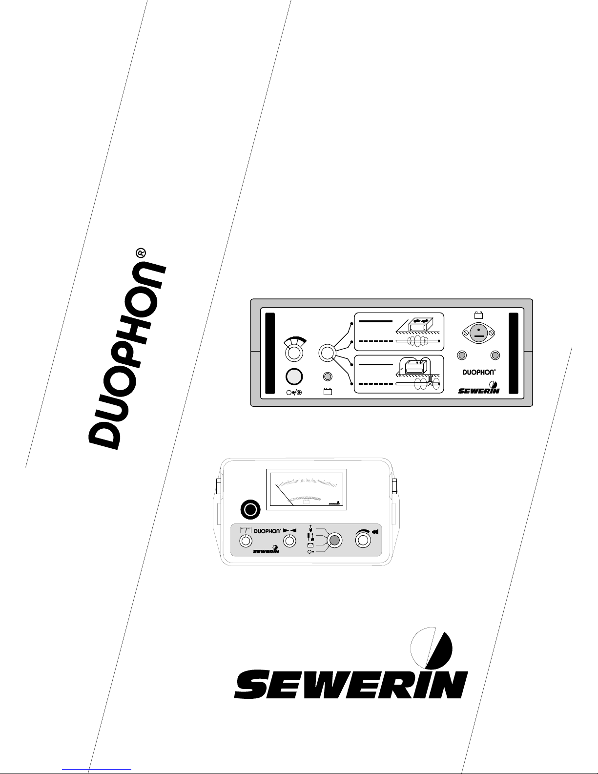
Aufbau des / Design of the : DUOPHON®
6040
8020
1000
+
-
+ -
+ -
1
2
3
4
1.1
1.3 1.4 6
1.2
5
8
9
10
11
12
13
13.1
13.2
13.3
13.4
14
15
16
17
7
6
Page 4

2
NOTIZEN / NOTES
Page 5

3
DUOPHON®
Betriebsanleitung ................Seite 5 - 24
Operating Instructions ........ page 25 - 44
100533 - 01/30.01.1996
Page 6

4
NOTIZEN / NOTES
Page 7

5
Das SEWERIN - Wasserlecksuch-/Leitungsortungssystem
DUOPHON®
Page 8

6
ZU IHRER SICHERHEIT
2
Das Gesetz über technische Arbeitsmittel (Gerätesicherheitsgesetz) vom
24.06.1968 (BGBl.I, Seite 717) und in der Fassung des Änderungsgesetzes
vom 13.08.1979 (BGBl.I, Seite 1432) schreibt vor, auf folgendes hinzuweisen:
BETRIEBSANLEITUNG BEACHTEN.
Jede Handhabung an dem Gerät setzt die genaue Kenntnis und Beachtung
dieser Betriebsanleitung voraus.
Das Gerät ist nur für die beschriebene Verwendung und den industriellen
(gewerblichen) Einsatz bestimmt.
HAFTUNG FÜR FUNKTION BZW. SCHÄDEN
Die Haftung für die Funktion des Gerätes geht in jedem Fall auf den
Eigentümer oder Betreiber über , soweit das Gerät von Personen, die nicht
dem SEWERIN-Service angehören, unsachgemäß gewartet oder
instandgesetzt wird oder wenn eine Handhabung erfolgt, die nicht der
bestimmungsgemäßen V erwendung entspricht.
Benutzen Sie daher immer das Original-SEWERIN-Zubehör zum Gebrauch
des DUOPHON®-Systems.
Für Schäden, die durch die Nichtbeachtung der vorstehenden Hinweise
eintreten, haftet die Firma Hermann Sewerin GmbH nicht. Gewährleistungsund Haftungsbedingungen der Verkaufs- und Lieferbedingungen der Hermann
Sewerin GmbH werden durch vorstehende Hinweise nicht erweitert.
Technische Änderungen im Rahmen einer Weiterentwicklung vorbehalten.
HERMANN SEWERIN GMBH
2
Soweit Hinweise auf Gesetze, Verordnungen und Normen gegeben werden, ist die
Rechtsordnung in der Bundesrepublik Deutschland zu Grunde gelegt.
Page 9

7
INHALT SEITE
ZU IHRER SICHERHEIT......................................................................... 6
1.0 Das DUOPHON®-System............................................................... 8
1.1 Der V erwendungszweck ............................................................... 9
1.2 Das Zubehör............................................................................... 10
2.0 Der DUOPHON®-Sender.............................................................. 11
3.0 Der DUOPHON®-Empfänger........................................................ 12
4.0 Die Ladetechnik/Stromversorgung ............................................. 13
5.0 Hinweise für die praktische Arbeit............................................... 14
5.1 DUOPHON® für die Wasserlecksuche ......................................... 14
5.1.1 V orortung mit dem Körperschallmikrofon.................................... 14
5.1.2 Lokalisation mit dem Bodenmikrofon.......................................... 15
5.2 DUOPHON® für die Leitungsortung .............................................. 16
5.2.1 Besendung der Leitung............................................................... 16
5.2.2 Bestimmung des Leitungsverlaufs.............................................. 17
5.2.3 Ortung nichtmetallischer Leitungen ............................................ 19
6.0 Die technischen Daten................................................................ 20
Konformitätserklärungen ........................................................................22
Page 10

8
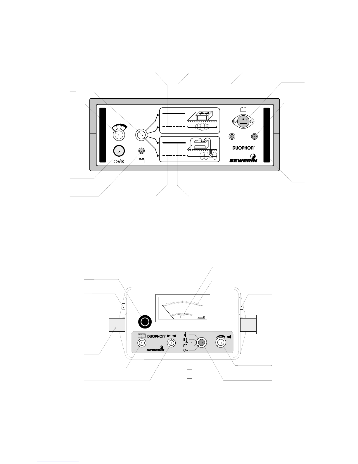
1.0 Das DUOPHON®-System
(Abbildung auf der vorderen Umschlaginnenseite aufklappen !)
SENDER
POS. BEZEICHNUNG FUNKTION
1 Drehschalter Sendebetriebsart:
1.1 Direkt - Impulston
1.2 Direkt - Dauerton
1.3 Indirekt - Impulston
1.4 Indirekt - Dauerton
2 Leistungssteller Einstellen der Sendeleistung
3 Ein/Aus-Taster Sender ein-/ausschalten
4 Kontroll-LED Anzeige von:
• Sender eingeschaltet
• Sender laden
5 Tragegriff
6 galvanischer Ausgang Anschlüsse für direkte
Besendung
7 Ladebuchse Ladeanschluß für:
• Steckernetzgerät
• Auto-Anschlußadapter
EMPFÄNGER
POS. BEZEICHNUNG FUNKTION
8 Mikrofontaste Einschalten des Mikrofons
( Wasserlecksuche)
9 Kopfhöreranschluß
Page 11

9
10 Tragegurt
11 Anzeigeempfindlichkeit
12 Feinabstimmung Einstellung auf die Sende-
frequenz ( Leitungsortung)
13 Drehschalter Betriebsart:
13.1 Gerät ausschalten
13.2 Batteriekontrolle
13.3 Wasserlecksuche
oder
Ortung stromführender
Kabel und kathodisch
geschützter Leitungen
13.4 Leitungsortung
14 Lautstärkeregler Einstellen der Kopfhörer-
Lautstärke
15 Anschluß Sonde für Körperschall-/Boden-
mikrofon oder Suchspule
16 Anzeige Signalstärke
17 Anzeige Batteriekapazität
1.1 Der Verwendungszweck
Das DUOPHON®-System kann sowohl für die elektro-akustische
Wasserlecksuche als auch für die Leitungsortung eingesetzt werden.
Bei der Wasserlecksuche erfolgt die Geräuschaufnahme über das
Körperschallmikrofon (Vorortung) und das Bodenmikrofon
(Lokalisation).
Die Ortung von Leitungsverläufen geschieht mit dem Empfänger
und der Suchspule. Dazu kann die Leitung direkt oder indirekt
besendet werden.
Stromkabel und kathodisch geschützte Leitungen können ebenfalls
geortet werden.
Page 12

10
1.2 Das Zubehör
Abhängig vom Einsatzzweck werden drei Systempakete angeboten:
• DUOPHON® als Wasserlecksuchgerät
- DUOPHON®-Empfänger ,
- Körperschallmikrofon KM 3/3,
- Verlängerung für das Körperschallmikrofon,
- Bodenmikrofon DT 3P,
- Kopfhörer,
- Tragetasche.
• DUOPHON® als Leitungsortungsgerät
- DUOPHON®-Empfänger,
- Suchspule FS 3A,
- Kopfhörer,
- DUOPHON®-Sender ,
- Steckernetzgerät,
- Auto-Anschlußadapter,
- Kabelsatz,
- Tragetasche.
• DUOPHON® als W asserlecksuch- und Leitungsortungsgerät
- DUOPHON®-Empfänger,
- Körperschallmikrofon KM 3/3,
- Verlängerung für das Körperschallmikrofon,
- Bodenmikrofon DT 3P,
- Suchspule FS 3A,
- Kopfhörer,
- DUOPHON®-Sender ,
- Steckernetzgerät,
- Auto-Anschlußadapter,
- Kabelsatz,
- Tragetasche.
Page 13

11
2.0 Der DUOPHON®-Sender
Das Gerät wird über den Taster (Pos. 3) ein- bzw. ausgeschaltet.
Die Kontroll-LED (Pos. 4) zeigt den Zustand des Senders an:
grün - Sendebetrieb,
rot blinkend - Akkuwarnung
(Restbetriebszeit mindestens 5 Minuten),
aus - Akku leer oder Sender ausgeschaltet.
Die gewünschte Betriebsart stellen Sie über den Drehschalter
(Pos. 1) ein.
Mit dem Leistungssteller (Pos. 2) kann die Sendeleistung in den
Stufen 25%, 50%, 75% und 100% eingestellt werden.
Hinweis!
Die Leistungsabgabe kann wesentlich erhöht werden, wenn Sie
den Sender mit der Kfz-Batterie verbinden (Pos. 7).
Wird der Sender 1 Stunde lang nicht bedient, so schaltet er sich
automatisch ab.
Page 14

12
3.0 Der DUOPHON®-Empfänger
In Position 13.1 ist das Gerät ausgeschaltet.
Die Kapazität der Batterien wird in Position 13.2 überprüft:
befindet sich der Zeiger im eng geblockten Bereich der
Anzeige (Pos. 17), so ist der Empfänger betriebsbereit.
Andernfalls sind die Batterien auszuwechseln (vgl. 4.0 Die
Ladetechnik/Stromversorgung).
Zum Einsatz in der elektro-akustischen Wasserlecksuche
bringen Sie den Drehschalter (Pos. 13) in Position 13.3 und
schließen das Körperschall- oder Bodenmikrofon (Pos. 15) und
den Kopfhörer an (Pos. 9).
Durch Betätigen der Mikrofontaste (Pos. 8) können Sie das
Geräuschsignal hören und die Signalstärke wird am Instrument
angezeigt (Pos. 16).
In dieser Betriebsart ist die Feinabstimmung (Pos. 12) ohne Funktion.
Soll der Empfänger zur Leitungsortung benutzt werden, bringen
Sie den Drehschalter (Pos. 13) in Position 13.4 und schließen die
Suchspule (Pos. 15) und den Kopfhörer (Pos. 9) an.
Die Signalstärke wird am Instrument angezeigt (Pos. 16). Mit der
Feinabstimmung (Pos. 12) stellen Sie den Empfänger auf die
Sendefrequenz ein.
In dieser Betriebsart ist die Mikrofontaste (Pos. 8) ohne Funktion.
Stromführende Kabel (50/60 Hz) und kathodisch geschützte
Leitungen (100 Hz) werden in Position 13.3 geortet. Dazu schließen
Sie die Suchspule (Pos. 15) und den Kopfhörer (Pos. 9) an. Durch
Betätigen der Mikrofontaste (Pos. 8) können Sie das Signal hören.
Zusätzlich lassen sich noch die Anzeigeempfindlichkeit (Pos. 11)
und die Kopfhörer-Lautstärke (Pos. 14) einstellen.
Page 15

13
4.0 Die Ladetechnik/Stromversorgung
SENDER
Über die Kontroll-LED (Pos. 4) wird der Zustand des DUOPHON®-
Senders angezeigt:
grün - Sendebetrieb,
1x grün blinkend - Ladebetrieb,
2x grün blinkend - Pufferbetrieb,
rot blinkend - Akkuwarnung
(Restbetriebszeit mindestens 5 Minuten),
aus - Akku leer oder Sender ausgeschaltet.
Das Nachladen (Pos. 7) erfolgt stationär über das Steckernetzgerät
(230 V≈/12 V=) oder mobil über die Kfz-Batterie (Auto-Anschlußadapter 12 V=/12 V= bzw . 24 V=/12 V=).
Nach ca. 14 Stunden ist der Akku vollgeladen und der Sender
schaltet vom Ladebetrieb in den Pufferbetrieb. Dort kann das
Gerät bis zum nächsten Einsatz verbleiben, ohne daß der Akku
durch Überladung Schaden nimmt.
EMPFÄNGER
In Position 13.2 wird die Batteriekapazität des DUOPHON®-
Empfängers überprüft:
befindet sich der Zeiger im weit geblockten Bereich der
Anzeige (Pos. 17), so sind die Batterien auszutauschen.
Der Empfänger ist mit acht 1,5 V Babyzellen ausgerüstet und
seine Betriebszeit beträgt mindestens 100 Stunden.
Page 16

14
5.0 Hinweise für die praktische Arbeit
5.1 DUOPHON® für die Wasserlecksuche
Das DUOPHON®-System dient u.a. der Feststellung von Leckstellen
an erdverlegten Leitungen nach dem Prinzip der elektroakustischen Wasserlecksuche.
5.1.1 Vorortung mit dem Körperschallmikrofon
Leckgeräusche, die von einer Rohrleitung übertragen werden
(Körperschall), können an zugänglichen Leitungsteilen oder
Armaturen vorgeortet werden (vgl. Abb. 1).
Abb. 1 - Vorortung mit dem Körperschallmikrofon
Dazu gehen Sie folgendermaßen vor:
• Tastspitze und eventuell Verlängerungen an das
Körperschallmikrofon KM 3/3 schrauben,
• Mikrofon mit dem DUOPHON®-Empfänger verbinden
(Pos. 15),
• Kopfhörer anschließen (Pos. 9),
• Drehschalter (Pos. 13) in Position 13.3 bringen,
• Körperschallmikrofon an die zu prüfenden Stellen bringen,
• Mikrofontaste (Pos. 8) drücken.
Page 17

15
Jetzt können Sie die verschiedenen Geräusche hören und
miteinander vergleichen. Die Signalstärken werden am Instrument
(Pos. 16) angezeigt.
5.1.2 Lokalisation mit dem Bodenmikrofon
Die Lokalisation der Leckstelle erfolgt über die Aufnahme des
Bodenschalles. Zwischen den Armaturen mit den lautesten
Geräusch-intensitäten wird die Trasse in regelmäßigen Abständen
abgehorcht (vgl. Abb. 2).
Abb. 2 - Lokalisation mit dem Bodenmikrofon
Dazu gehen Sie folgendermaßen vor:
• Bodenmikrofon DT 3P mit dem DUOPHON®-Empfänger
verbinden (Pos. 15),
• Kopfhörer anschließen (Pos. 9),
• Drehschalter (Pos. 13) in Position 13.3 bringen,
• Bodenmikrofon auf die Trasse setzen,
• Mikrofontaste (Pos. 8) drücken.
Die maximale Geräuschintensität kennzeichnet die Position der
Leckstelle.
Page 18

16
5.2 DUOPHON® für die Leitungsortung
Das DUOPHON®-System dient u.a. der Ortung von erdverlegten
Leitungen.
5.2.1 Besendung der Leitung
Die gewünschte Betriebsart wird über den Drehschalter (Pos. 1)
eingestellt:
Direkte Besendung - Impulston : Position 1.1,
Direkte Besendung - Dauerton : Position 1.2,
Indirekte Besendung - Impulston : Position 1.3,
Indirekte Besendung - Dauerton : Position 1.4.
Soll die zu ortende Leitung direkt besendet werden (vgl. Abb. 3),
stellen Sie eine Verbindung zwischen Sender-Erdspieß und
zwischen Sender-Leitungsarmatur her (Pos. 6). Der Erdspieß
sollte in einigen Metern Entfernung rechtwinklig zum Leitungsverlauf
in den Boden gesteckt werden.
Abb.3
Direkte Besendung einer
Leitung
Bei der indirekten Besendung (vgl. Abb. 4) stellen Sie den
Sender so auf die Trasse, daß die Pfeile (Aufkleber) nach oben
und in Richtung der Leitung zeigen.
Abb.4
Indirekte Besendung einer
Leitung
Wird der Sender eingeschaltet (Pos. 3) kann das "10 kHz"-Signal
über der Trasse emp fangen werden.
Page 19

17
5.2.2 Bestimmung des Leitungsverlaufs
Wird eine Leitung besendet, so breitet sich ringförmig um sie ein
magnetisches Feld aus. Zur Ortung dieses Feldes gehen Sie
folgendermaßen vor:
• Suchspule FS 3A mit dem DUOPHON®-Empfänger verbinden
(Pos. 15),
• Kopfhörer anschließen (Pos. 9),
• Drehschalter (Pos. 13) in Position 13.4 bringen oder
• Drehschalter (Pos. 13) in Position 13.3 bringen und
Mikrofontaste (Pos. 8) drücken ( bei stromführenden
Kabeln und kathodisch geschützten Leitungen),
• Suchspule über die Trasse führen.
Die Suchspule nicht um den Handknauf pendeln
lassen - falsche Anzeigewerte sind die Folge !
MINIMUMMETHODE
Bei der Minimummethode wird die Suchspule in 0 Grad-Stellung
eingerastet (vgl. Abb. 5).
Abb. 5
Minimummethode
Das magnetische Feld erzeugt den abgebildeten Signalverlauf
und kann über die Anzeige (Pos. 16) und den Kopfhörer (Pos. 9)
kontrolliert werden.
Page 20

18
Mit der Feinabstimmung (Pos. 12) stellen Sie die Signalqualität
ein.
Das Minimum wird genau über der Leitung detektiert. So kann der
Verlauf der Leitung verfolgt werden.
MAXIMUMMETHODE
Bei der Maximummethode wird die Suchspule in 90 Grad-Stellung
eingerastet (vgl. Abb. 6).
Abb. 6
Maximummethode
Das magnetische Feld erzeugt den abgebildeten Signalverlauf
und kann wieder über die Anzeige (Pos. 16) und den Kopfhörer
(Pos. 9) kontrolliert werden.
Hier wird über der Leitung das größte Maximum detektiert.
Mit der Minimummethode ist die Lage der Leitung genauer zu
orten, da das scharf ausgeprägte Minimum besser zu detektieren
ist, als das breit ausgeprägte Maximum der Maximummethode.
Page 21

19
TIEFENBESTIMMUNG
Zuerst stellen Sie die genaue Position der Leitung über die
Minimummethode fest. Für die Tiefenbestimmung wird jetzt die
Suchspule in 45 Grad-Stellung eingerastet (vgl. Abb. 7).
Abb. 7
Tiefenbestimmung
In den eingezeichneten Stellungen lassen sich links und rechts
von der Leitung 2 Minima detektieren.
Der Abst and zwischen der T rasse und einem Minimum entspricht
dann der Verlegungstiefe.
Zum Ausgleich von nicht ganz kreisförmigen Magnetfeldern ergibt
sich die Verlegungstiefe als der halbe Abstand zwischen den
beiden Minima.
5.2.3 Ortung nichtmetallischer Leitungen
Nichtmetallische Leitungen (z.B. PVC, PE, Asbest-Zement, Beton
oder Steinzeug) können in Verbindung mit dem SEWERIN
Glasfaser-Sonden-System GFS/GSK geortet werden.
Der Anschluß erfolgt, genau wie bei der direkten Besendung, am
galvanischen Ausgang (Pos. 6).
Page 22

20
6.0 Die technischen Daten
SENDER
Fabrikations-Nr. : 013 02 . . . . . .
Funktion : Signalgenerator mit integrierter
Rahmenspule
Frequenz : 9,95 kHz
Signalform : Impuls- oder Dauerton
Sendeleistung : 3,5 Watt (galvanisch)
Stromversorgung : NiCd-Akku
Laden : 12 V=, integrierter Timer, Puffer-
technik, Schutzabschaltung und
Zustandsanzeige
Betriebszeit : max. 12 h (Impulston),
max. 6 h (Dauerton)
Betriebstemperatur : -10° bis +40° Celsius
Lagertemperatur : -20° bis +60° Celsius
Maße (BxHxT) : 270 x 170 x 105 mm
Gewicht : 2.700 g
EMPFÄNGER
Fabrikations-Nr. : 012 02 . . . . . .
Funktion : Signalempfang, Verstärker
und Frequenzfilter
Page 23

21
Frequenzbereiche
- Wasserlecksuche : Breitband
(20 Hz bis 4 kHz)
- Leitungsortung : 50/100 Hz passiv
(Stromkabel oder kathodisch
geschützte Leitungen),
9,95 kHz Senderfrequenz
Stromversorgung : 8 x 1,5 V Babyzellen (R 14/LR 14)
Betriebszeit : > 100 h
Betriebstemperatur : -10° bis +40° Celsius
Lagertemperatur : -20° bis +60° Celsius
Maße (BxHxT) : 175 x 145 x 105 mm
Gewicht : 1.600 g
Page 24

22
Konformitätserklärung DUOPHON®
Page 25

23
Konformitätserklärung DUOPHON®
Page 26

24
Notizen
Page 27

25
The SEWERIN - System
for Water Leak Detection and Pipe Location
DUOPHON®
Page 28

26
2
FOR YOUR SAFETY
2
The law relating to technical instruments (Gerätesicherheitsgesetz) of
June 24th, 1968 (Federal law gazette I, page 717), and the amended
law of August 13th, 1979 (Federal law gazette I, page 1432) prescribe
the following instruction:
PAY ATTENTION TO THE OPERATING INSTRUCTIONS.
Any operation of this instrument presumes exact knowledge of and
adherence to these operating instructions.
The device is intended only for the utilization described and industrial
(commercial) use.
LIABILITY FOR FUNCTION AND/OR DAMAGES
The liability for function is transferred to the owner or user in all cases
where the device has been incorrectly serviced or repaired by persons
other than members of the SEWERIN service team, and when it is
operated in a way which does not correspond to its agreed use.
For this reason, always use original SEWERIN accessories for the
DUOPHON®.
Hermann Sewerin GmbH do not accept liability for any damages
resulting from non-observance of these instructions. The guarantee
and liability conditions contained in our general terms of sale and
delivery are not extended by the above indications.
The device may be subject to technical change within the scope of
further development.
HERMANN SEWERIN GMBH
Insofar as reference is made to laws, regulations and standards, these are based on the legal
order in the Federal Republic of Germany.
Page 29

27
CONTENTS PAGE
FOR YOUR SAFETY............................................................................. 24
1.0 The DUOPHON® System ............................................................. 26
1.1 Purpose ...................................................................................... 27
1.2 Accessories ................................................................................ 28
2.0 The DUOPHON® T ransmitter ....................................................... 29
3.0 The DUOPHON® Receiver ........................................................... 30
4.0 Charging / Current Supply .......................................................... 31
5.0 Tips for Field Work ..................................................................... 32
5.1 Water Leak Detection with the DUOPHON®................................. 32
5.1.1 Prelocation with the Bodysound Microphone .............................. 32
5.1.2 Localization with the Ground Microphone ................................... 33
5.2 Pipe Location with the DUOPHON®.............................................. 34
5.2.1 Energizing of a Pipeline .............................................................. 34
5.2.2 Determination of a Pipe Position ................................................ 35
5.2.3 Localization of non-metallic Pipelines ......................................... 37
6.0 Technical Specification ............................................................... 38
Declarations of Conformity .....................................................................42
Page 30

28
1.0 The DUOPHON® System
(Refer to picture on inner front page)
Transmitter
ITEM NAME FUNCTION
1 Rotary Switch Choice of Operating Mode:
1.1 Direct - Pulse tone
1.2 Direct - Constant tone
1.3 Indirect - Pulse tone
1.4 Indirect - Constant tone
2 Output Control Selection of Transmitter
Output
3 On/Off Key Switching T ransmitter On or
Off
4 Control LED Indication of:
• Transmitter switched-on
• Transmitter requires charging
5 Carrying handle
6 Galvanic Outlet Connection for direct
energizing
7 Charging Socket Connection for:
• Power Supply Set
• Car Adapter
RECEIVER
ITEM NAME FUNCTION
8 Microphone Switch Switching-on the microphone
( Water Leak Detection)
9 Earphone Connection
Page 31

29
10 Carrying Belt
11 Sensitivity Control
12 Fine Tuning Adjustment of transmitting
frequency ( Pipe Location)
13 Rotary Switch Operating Mode:
13.1 Switching-off
13.2 Battery Control
13.3 Water Leak Detection
or
Locating of power carrying cables and
cathodically protected
pipes
13.4 Pipe Location
14 Volume Control Adjustment of Volume
15 Probe Connection for Bodysound or Ground
Microphone or Search Coil
16 Indication of Signal Intensity
17 Indication of Battery Capacity
1.1 Purpose
The DUOPHON® System is designed for the electro-acoustic water
leak detection as well as for pipe location.
When detecting water leaks the sound pick-up is effected either via
the bodysound microphone (prelocation) or the ground microphone
(localization).
The localization of pipes is carried out with receiver and search coil.
For this purpose the pipe can be energized either directly or
indirectly.
Power carrying cables and cathodically protected pipes can also be
located.
Page 32

30
1.2 Accessories
Three DUOPHON® Systems can be offered for various operations:
• Water Leak Detector DUOPHON® with
- Receiver,
- Bodysound Microphone Type KM 3/3,
- Microphone Extension,
- Ground Microphone Type DT 3P,
- Earphones,
- Carrying Bag.
• Pipe Locator DUOPHON® with
- Receiver,
- Search Coil Type FS 3A,
- Earphones,
- Transmitter,
- Power Supply Set,
- Car Adapter,
- Set of Cables,
- Carrying Bag.
• DUOPHON® Combination for W ater Leak Detection and Pipe
Location with
- Receiver ,
- Bodysound Microphone T ype KM 3/3,
- Microphone extension,
- Ground Microphone Type DT 3P,
- Search Coil Type FS 3A,
- Earphones,
- Transmitter,
- Power Supply Set,
- Car Adapter,
- Set of Cables,
- Carrying Bag.
Page 33

31
2.0 The DUOPHON® Transmitter
The transmitter is switched on- or off by key (Item 3).
The Control LED (Item 4) indicates the state of the transmitter:
green - Operating Mode,
red blinking - Charging required (Remaining operating
time at least 5 minutes),
off - Battery discharged or transmitter switched-
off.
The required operating mode is adjusted by the rotary switch
(Item 1).
With the output control (Item 2) the transmission output can be
adjusted to steps 25 %; 50 %; 75 % or 100 %.
NOTE!
The transmitter’ s output can be considerably increased when the
transmitter is connected to the car battery (Item 7).
When the transmitter will not be operated f or 1 hour it switches-off
automatically.
Page 34

32
3.0 The DUOPHON® Receiver
The receiver is s witched off when in Position 13.1.
When in Position 13.2 the battery capacity will be checked:
When the pointer is within the tightly blocked range of the scale
(Item 17) the receiver is ready for operation. Otherwise the
batteries have to be exchanged (Ref er to paragr . 4.0 „Charging/
Current Supply").
When electro-acoustic water leak detection shall be made the
rotary switch (Item 13) must be in position 13.3 and the bodysound
or the ground microphone (Item 15) as well as the earphones (Item
9) have to be connected to the DUOPHON®.
By pushing the microphone key (Item 8) the picked-up sound can
be heard and the sound intensity will be displayed on the instrument
(Item 16).
In this operating mode the fine tuning (Item 12) has no function.
When the receiver shall be used for pipe location the rotary switch
(Item 13) must be in position 13.4 and the search coil (Item 15) and
the earphones (Item 9) have to be connected to the DUOPHON®.
The sound intensity will be displayed on the instrument (Item 16).
The transmitting frequency will be selected with the fine tuning
(Item 12).
In this operating mode the microphone key (Item 8) has no function.
Power carrying cables (50/60 Hz) and cathodically protected
pipes (100 Hz) can be located with the rotary switch in position
13.3. The search coil (Item 15) and the earphones (Item 9) hav e to
be connected. By pushing the microphone key (Item 8) the signal
can be received.
When required, the sensitivity control (Item 11) and the volume
(Item 14) can be adjusted.
Page 35

33
4.0 Charging/Current Supply
TRANSMITTER
The control LED (Item 4) indicates the condition of the DUOPHON®
transmitter:
green - operation,
green blinking once - charging,
green blinking twice - buffering,
red blinking - charging necessary
(Remaining operating time
at least 5 minutes),
off - Battery discharged or
transmitter switched-off.
Recharging (Item 7) is effected stationary via the Power Supply Set
(230 V /12 V ) or from the car battery (Car Adapter 12 V/12 V or 24
V/12 V).
After about 14 hours’ charging the battery is fully charged and the
transmitter switches from charging to buffering. The transmitter can
remain there without the battery becoming damaged by overcharging.
RECEIVER
With the rotary switch in position 13.2 the battery’s capacity of the
DUOPHON® receiver will be checked:
When the pointer is in the widely blocked range of the scale
(Item 17) the batteries have to be exchanged.
The receiver is equipped with eight 1.5 dry cells and has an
operating time of at least 100 hours.
Page 36

34
5.0 Tips for field work
5.1 DUOPHON® for water leak detection
One purpose of the DUOPHON® is the detection of leaks on
underground pipelines by the electro-acoustic method of water leak
detection.
5.1.1 Prelocation with the bodysound microphone
Leak noises that are transmitted by the pipeline (bodysound) can
be prelocated at accessible parts of the pipe or on fittings (Refer to
Pict.1).
Pict. 1 - Prelocation with the bodysound microphone
Proceed as follows:
• Screw tip and extensions, if required, to the bodysound
microphone type KM 3/3,
• Connect microphone to the DUOPHON® receiver (Item 15),
• Connect earphones (Item 9),
• Turn rotary switch (Item 13) into position 13.3,
• Move bodysound microphone to the places that shall be
checked,
• Push microphone key (Item 8).
Page 37

35
Now the different sounds can be receiv ed and compared with each
other. The sound intensities are displayed on the instrument
(Item 16).
5.1.2 Localization with the ground microphone
For the localization of leaks the sound transmitted by the ground is
picked-up. Between fittings where the highest sound intensities
have been measured the ground microphone will be placed down
in regular distances (Refer to Pict.2).
Pict.2 -Localization with the Ground Microphone
Proceed as follows:
• Connect ground microphone type DT 3P to the DUOPHON®
receiver (Item 15),
• Connect earphones (Item 9),
• Turn rotary switch (Item 13) into position 13.3,
• Place ground microphone on the trace,
• Push microphone key (Item 8).
The maximum sound intensity signalizes the leak position.
Page 38

36
5.2 Pipe location with the DUPOHON®
Another purpose of the DUOPHON® System is the location of
underground pipelines.
5.2.1 Energizing of a pipe
The requested operating mode is adjusted with rotary switch
(Item 1):
Direct energizing - pulse tone position 1.1
Direct energizing - constant tone position 1.2
Indirect energizing - pulse tone position 1.3
Indirect energizing - constant tone position 1.4
When the pipeline shall be energized directly (Refer to pict.3) a
connection must be made between the transmitter/earth plug and
between the transmitter and a pipe fitting (Item 6). The earth plug
should be pushed into the soil within a few meters’ distance and
rectangular to the pipeline.
Pict. 3
Direct energizing of a
pipeline
For an indirect energizing (Refer to pict.4) the transmitter must be
placed onto the trace such way that both arrows (stickers) are on
top of the device pointing to both directions of the pipeline.
Pict. 4
Indirect energizing of a
pipeline
After switching-on the transmitter (Item 3) the „10 kHz“ signal can
be received above the pipe’s trace.
Page 39

37
5.2.2 Determination of the pipe position
When a pipeline is energized a magnetic field of force is created
ring-shaped around the pipe. T o locate this field of f orce proceed as
follows:
• Connect search coil type FS 3A to the DUOPHON®
receiver (Item 15)
• Connect earphones (Item 9)
• Turn rotary switch (Item 13) into position 13.4 or
• Turn rotary switch (Item 13) into position 13.3 and push
microphone key (Item 8) (when power carrying cables
and cathodically protected pipes are concerned)
• Move search coil along the pipe’s trace.
Don’t let the search coil swing around the handle -
wrong values would be indicated !
MINIMUM METHOD
When the minimum method shall be applied the search coil will be
clicked into 0 degree position (Refer to pict.5)
Pict. 5
Minimum Method
The magnetic field of force produces the signal course as pictured
above. This can be controlled via the meter (Item 16) and the
earphones (Item 9).
Page 40

38
With the fine tuning (Item 12) the signal quality can be adjusted.
The minimum will be received e xactly above the pipeline. Thus its
trace can be followed.
MAXIMUM METHOD
For the application of the maximum method the search coil will be
clicked into 90 degree position (refer to pict.6)
Pict. 6
Maximum method
The magnetic field of force produces a course of signals as
pictured. This can also be controlled via the meter (Item 16) and the
earphones (Item 9).
Using this method the maximum indicates the pipe position.
Howe ver , with the minimum method the position of the pipe can be
detected more exactly since the sharply defined minimum can be
better received than the less distinct maximum.
Page 41

39
DEPTH DETERMINATION
Before the depth determination the exact position of the pipe must
be detected with the minimum method. Then the search coil will be
clicked into 45 degree position for the depth determination (refer
to pict.7).
Pict. 7
Depth determination
As marked in the picture 2 minima can be detected at the right and
at the left side of the pipeline.
The distance between the trace and one of the minima is the depth
where the pipe has been laid.
In case the magnetic fields of force are not exactly circular half the
distance between the two minima mark the depth of the pipe.
5.2.3 Localization of non-metallic pipelines
Non-metallic pipelines (like thos of PVC, PE, asbestos-cement,
concrete or stone) can be detected by means of the SEWERIN
Glasfibre Probe System GFS/GSK. This system is connected to the
galvanic outlet of the DUOPHON® (Item 6) which is used for direct
energizing.
Page 42

40
6.0 T echnical Specification
TRANSMITTER
Serial No. : 013 02. . . . .
Function : Signal generator with
integrated frame coil
Frequency : 9.95 kHz
Kind of signal : Pulse or constant signal
Output : 3.5 Watt (galvanic)
Power supply : NiCd batteries
Charging : 12 V , integrated timer, buff ering
technique, safety s witch-off and
indication of the state
Operating time : max. 12 h (pulse tone),
max. 6 h (constant tone)
Operating temperature : -10° - + 40° Celsius
Storing temperature : -20° - + 60° Celsius
Dimensions (WxHxD) : 270 x 170 x 105 mm
Weight : 2,700 g
RECEIVER
Serial No. : 012 02 . . . . .
Function : Signal receiver, amplifier and
frequency filter
Page 43

41
Frequency ranges
- W ater Leak Detection : Wideband (20 Hz to 4 kHz)
- Pipe location : 50/100 Hz passive (power
carrying cables or cathodically
protected pipelines)
9.95 kHz transmitting frequency
Power supply : 8 1.5 V Dry Cells (R14/LR14)
Operating time : > 100 h
Operating temperature : -10° - + 40° Celsius
Storing temperature : - 20° - + 60° Celsius
Dimensions (WxHxD) : 175 x 145 x 105 mm
Weight : 1,600 g
Page 44

42
Declaration of Conformity DUOPHON®
Page 45

43
Declaration of Conformity DUOPHON®
Page 46

44
Notes
Page 47

Robert-Bosch-Straße 3 · D-33334 Gütersloh
Telefon +49 - (0) - 52 41/9 34-0 · Telefax +49 - (0) - 52 41/9 34-4 44
Hermann Sewerin GmbH
http://www.sewerin.com
 Loading...