

SEW MOVITRAC LTP series Operating Instructions Manual
Drive Technology \ Drive Automation \ System Integration \ Services
MOVITRAC
Edition 12/2008
16766016 / EN
®
LTP
Operating Instructions

SEW-EURODRIVE – Driving the world

1 Important Notes................................................................................................. 4
1.1 Structure of the safety notes ..................................................................... 4
1.2 Application environment............................................................................ 5
1.3 Waste disposal.......................................................................................... 5
2 Safety Notes ......................................................................................................6
2.1 Installation and startup .............................................................................. 6
2.2 Operation and servicing ............................................................................ 7
3 General specifications ...................................................................................... 8
3.1 Input voltage ranges ................................................................................. 8
3.2 Product designation .................................................................................. 9
3.3 Overload capability ................................................................................... 9
3.4 Protection features .................................................................................. 10
4 Mechanical Installation ................................................................................... 11
4.1 Dimensions ............................................................................................. 12
4.2 IP20 / NEMA 1 housing: mounting and dimensions................................ 14
5 Electrical Installation ...................................................................................... 16
5.1 Prior to installation .................................................................................. 16
5.2 Installation............................................................................................... 18
5.3 Optical interface ...................................................................................... 24
5.4 UL-compliant installation ......................................................................... 24
5.5 Electromagnetic compatibility.................................................................. 26
6 Startup.............................................................................................................. 27
6.1 Operating the keypad.............................................................................. 27
6.2 Easy startup ............................................................................................ 28
7 Operation and Service .................................................................................... 30
7.1 Drive status ............................................................................................. 30
7.2 Fault codes and history ........................................................................... 31
7.3 SEW electronics service ......................................................................... 33
8 Parameters....................................................................................................... 34
8.1 Parameter access and reset ................................................................... 34
8.2 Parameter specifications: ....................................................................... 36
8.3 Selection of Parameter P2-01, Digital Input Function............................. 43
9 Software ........................................................................................................... 49
9.1 MODBUS Control.................................................................................... 49
10 Technical data ................................................................................................. 55
10.1 Conformance .......................................................................................... 55
10.2 Environmental ......................................................................................... 55
10.3 Output power and current ratings............................................................ 56
11 Index ................................................................................................................. 65
Operating Instructions– MOVITRAC® LTP
3
1
Important Notes
Structure of the safety notes
1 Important Notes
erschöpftOperating Instructions
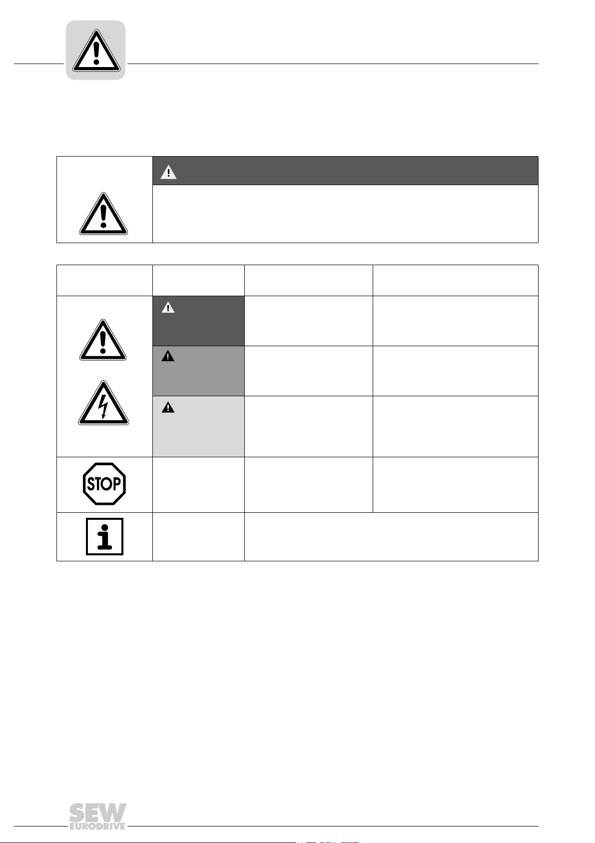
1.1 Structure of the safety notes
The safety notes in these operating instructions are structured as follows:
Symbol SIGNAL WORD
Nature and source of hazard.
Possible consequence(s) if disregarded.
• Measure(s) to avoid the hazard.
Symbol Signal Word Meaning Consequences if
disregarded
Example:
General hazard
HAZARD Imminent hazard Severe or fatal injuries
WARNING Possible hazardous situation Severe or fatal injuries
Specific hazard,
e.g. electric shock
CAUTION Possible hazardous situation Minor injuries
STOP Possible damage to property Damage to the drive system or its environ-
ment
NOTE Useful information or tip
Simplifies drive system handling
Unless the information in the operating instructions is adhered to, it will be impossible to
ensure:
• Trouble-free operation
• Fulfillment of any rights to claim under guarantee
Consequently, read the operating instructions before you start working with the
unit!
The operating instructions contain important information about servicing. Therefore,
keep the operating instructions close to the unit.
4
Operating Instructions – MOVITRAC® LTP

1.2 Application environment
The following applications are forbidden unless measures are expressly taken to make
them possible:
• Use in explosion-proof areas.
• Use in environments with harmful substances:
– Oils
–Acids
– Gases
– Vapors
–Dust
– Radiated interference
– Other harmful environments
• Use subject to mechanical vibration and shock loads in excess of the requirements
in EN 50178.
• If the inverter performs safety functions which have to guarantee the protection of
machinery and people.
Important Notes
Application environment
1
1.3 Waste disposal
Please follow the current instructions: dispose in accordance with the regulations in
force:
• Electronics scrap (printed-circuit boards)
• Plastic (housing)
• Sheet metal
• Copper
Operating Instructions – MOVITRAC® LTP
5

2
Safety Notes
Installation and startup
2 Safety Notes
MOVITRAC® LTP drive inverters may not perform safety functions without higher-level
safety systems.
Use higher-level safety systems to guarantee the protection of machinery and people.
Do not use MOVITRAC
hoist applications.
Use monitoring systems or mechanical protection devices as safety features to avoid
possible injury or damage to property.
2.1 Installation and startup
• Never install or operate damaged products. Please submit a complaint to the
• Installation, startup and service work on the unit only by trained personnel.
• Follow the specific instructions during installation and startup of the motor and
• Make sure that preventive measures and protection devices correspond to the
• The unit meets all requirements for reliable isolation of power and electronics
• Take suitable measures to ensure that the connected motor does not start up
• Integral solid state short circuit protection does not provide branch circuit pro-
®
LTP drive inverters for any safety functions in conjunction with
transport company immediately in the event of damage.
The personnel must be trained in the relevant aspects of accident prevention andmust comply with the regulations in force (e.g. EN 60204, VBG 4,
DIN-VDE 0100/0113/0160).
the brake!
applicable regulations (e.g. EN 60204 or EN 50178).
Grounding the unit is a necessary protective measure.
Overcurrent protection devices are a necessary protective measure.
connections in accordance with UL508. All connected circuits must also satisfy
the requirements for reliable isolation so as to guarantee reliable isolation.
automatically when the inverter is switched on. To do this, you can connect binary
inputs DI01 through DI03 to GND.
tection. Branch circuit protection must be provided in accordance with the National
Electrical Code and any additional local codes.
6
Operating Instructions – MOVITRAC® LTP

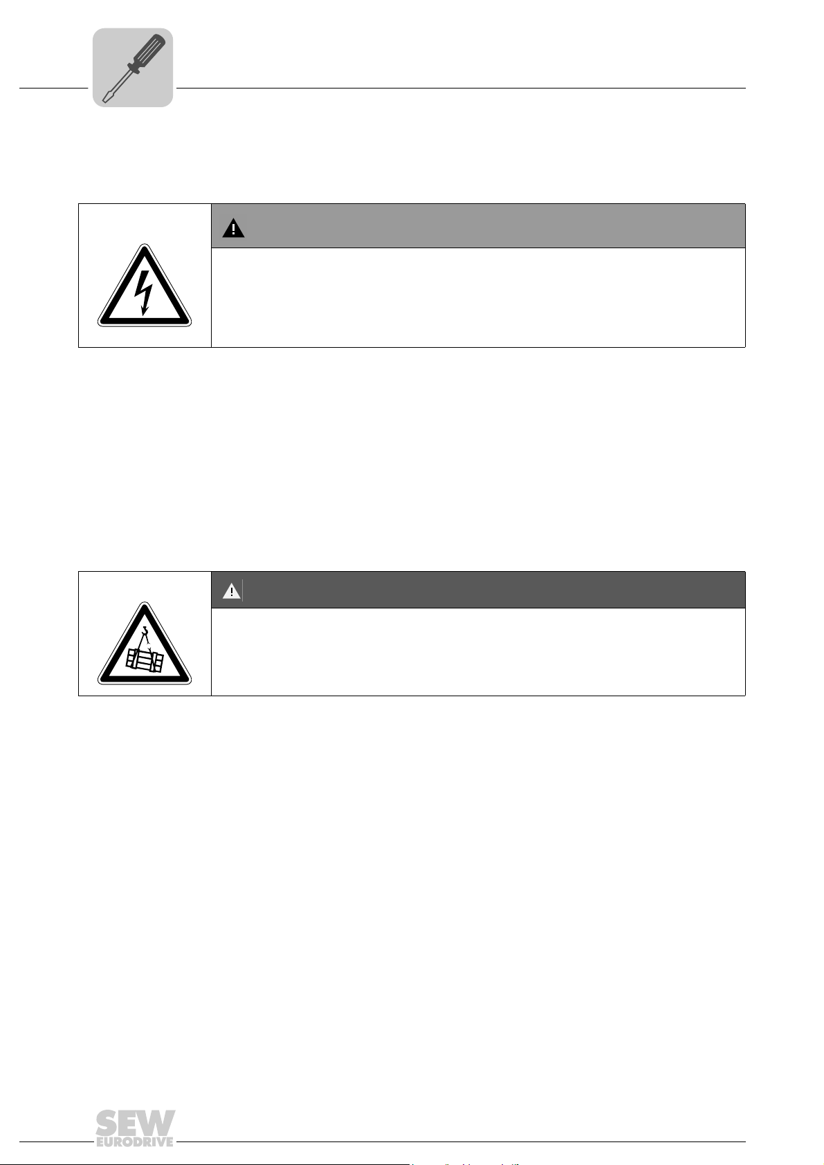
2.2 Operation and servicing
WARNING
Danger of electrical shock. High voltages are present in the terminals and in within the
drive for up to 10 minutes after the electrical supply has been disconnected.
Severe or fatal injuries.
• Disconnect and isolate the MOVITRAC
minutes before commencing any work on it.
• Dangerous voltages are present in the output terminals and the cables and
motor terminals connected to them when the unit is switched on. Dangerous
voltages may also be present when the unit is inhibited and the motor at a standstill.
• The unit is not necessarily deenergized when the LEDs and the 7-segment
display are off.
• Safety functions inside the unit or a mechanical blockage may cause the motor
to stop. The removal of the source of the malfunction or a reset can result in an
automatic restart of the drive. If, for safety reasons, this is not permissible for the
driven machine, disconnect the unit from the supply system before correcting the
fault.
Safety Notes
Operation and servicing
®
LTP from the electrical supply at least 10
2
Operating Instructions – MOVITRAC® LTP
7
kVA
3
i
n
f
General specifications
Input voltage ranges
Hz
P
3 General specifications
3.1 Input voltage ranges
Depending upon model and power rating, the drives are designed for direct connection
to the following supplies:
MOVITRAC
200 ... 240 V ± 10 %, 1-phase* / 3-phase, 50 … 60 Hz ± 5 %
NOTE
*It is also possible to connect 1-phase MOVITRAC® LTP units to 2-phases of a
200 ... 240 V, 3-phase mains.
®
LTP 240 V units:
MOVITRAC
380 ... 480 V ± 10 %, 3-phase, 50 … 60 Hz ± 5 %
MOVITRAC
480 ... 525 V ± 10 %, 3-phase, 50 … 60 Hz ± 5 % (Sizes 5 & 6 only)
MOVITRAC
500 ... 600 V ± 10 %, 3-phase, 50 … 60 Hz ± 5 %
Products used with a 3-phase supply are designed for a maximum supply imbalance of
3 % between phases. For input supplies which have a supply imbalance greater than
3 % (typically the Indian subcontinent and parts of Asia Pacific including China) we
recommend that input chokes are used.
®
LTP 400 V units:
®
LTP 525 V units:
®
LTP 575 V units:
8
Operating Instructions – MOVITRAC® LTP
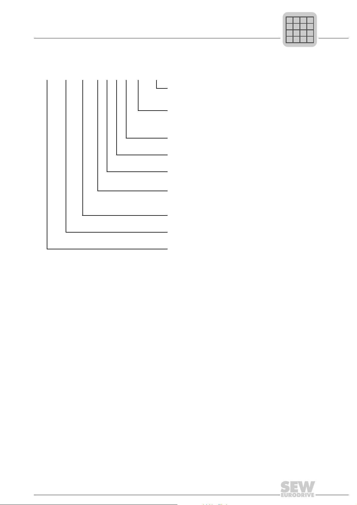
3.2 Product designation
MC LTP A 0015 2 0 1 1 00 (60 Hz)
General specifications
Product designation
60 Hz American version only
00 = Standard IP20 / NEMA 1 housing
10 = IP55 / NEMA 12 housing
Type
Quadrants
20 = IP55 / NEMA 12 housing with switch
50 = 525 V, standard IP20 / NEMA 1 housing
0M = Optional Modbus Firmware
1 = 1Q (without brake chopper)
4 = 4Q (with brake chopper)
kVA
i
n
f
Hz
P
3
3.3 Overload capability
All MOVITRAC® LTP units have a possible overload of:
• 150 % for 60 seconds
• 175 % for 2 seconds
Connection type
Interference
suppression on the
supply side
Mains voltage
Recommended motor
power
Version A
Product type MC LTP
1 = 1-phase
3 = 3-phase
0 = class 0
A = class A
B = class B
1 = 115 V
2 = 200 ... 240 V
5 = 380 ... 480 V
6 = 500 ... 600 V
0015 = 1.5 kW
Operating Instructions – MOVITRAC® LTP
9

kVA
3
i
n
f
General specifications
Protection features
Hz
P
3.4 Protection features
• Output short-circuit, phase-to-phase, phase-to-ground
• Output over-current
– Trip set at 175 % of rated drive current.
• Overload protection
– Drive delivers 150 % of rated motor current for 60 seconds.
• Braking transistor protected against short-circuit.
• Braking resistor overload (when enabled)
• Over-voltage trip
– Set at 123 % of drive maximum rated supply voltage.
• Under-voltage trip
• Over temperature trip
• Under temperature trip
– Drive will trip if enabled below –10 °C
• Supply phase imbalance
– A running drive will trip if there is a supply imbalance of >3 % persisting for
more than 30 seconds.
• Supply phase loss
– A running drive will trip if one phase of a 3-phase supply is lost for more than
15 seconds.
10
Operating Instructions – MOVITRAC® LTP

4 Mechanical Installation
• Carefully inspect the MOVITRAC® LTP prior to installation to ensure it is undamaged.
• Store the MOVITRAC
and within the ambient temperature range –40 °C to +60 °C.
• Install the MOVITRAC
within suitable housing. This should be according to EN 60529 if specific Ingress
Protection ratings are required.
• Do not place flammable material close to the drive.
• The entry of conductive or flammable foreign bodies should be prevented.
• The maximum operational ambient temperature is 50 °C and the minimum is 0 °C.
• Relative humidity must be less than 95 % (non-condensing).
•MOVITRAC
touching. This gives adequate ventilation space between them. If the
MOVITRAC
device, the minimum vertical spacing is 150 mm. The enclosure should either be
force-ventilated or large enough to allow natural cooling (see chapter "IP20 / NEMA
1 housing: mounting and dimensions" on page 14).
®
LTP units can be installed side by side with their heatsink flanges
®
LTP is to be installed above another drive or any other heat-producing
Mechanical Installation
Protection features
®
LTP in its box until required. Storage should be clean and dry
®
LTP on a flat, vertical, flame-resistant, vibration-free surface,
4
Operating Instructions – MOVITRAC® LTP
11
4
A
Mechanical Installation
Dimensions
4.1 Dimensions
MOVITRAC® LTP is available in 2 housing versions:
• Standard IP20 / NEMA 1 housing for use in switch cabinets
• IP55 / NEMA 12 K version for size 1 and size 2 drives
The IP55 / NEMA 12 K housing is protected against moisture and dust. Therefore, the
drives can be operated indoors under harsh conditions. Electronically, the drives are
identical and the only differences are the dimensions of the housing and the weight.
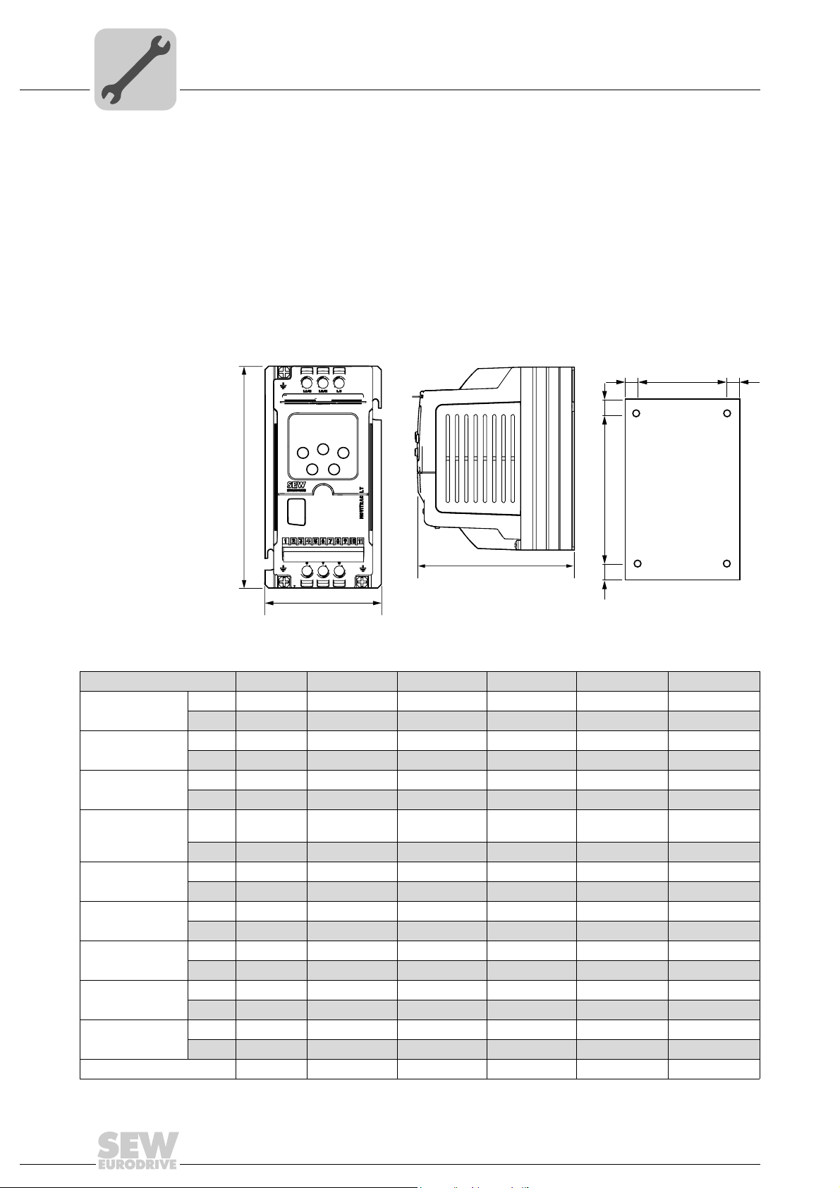
4.1.1 Dimensions of the IP20 / NEMA 1 housing
bb
c
d
C
B
54769AXX 54781AXX 54770AXX
Dimension Size 1 Size 2 Size 3 Size 4 Size 5 Size 6
Height (A) [mm] 155 260 260 520 1045 1100
[in] 6.10 10.20 10.20 20.47 41.14 43.31
Width (B) [mm] 80 100 171 340 340 340
[in] 3.15 3.94 6.73 13.39 13.39 13.39
Depth (C) [mm] 130 175 175 220 220 330
[in] 5.12 6.89 6.89 8.66 8.66 12.99
Weight
a [mm] 72 92 163 320 320 320
b [mm] 4 4 4 9.5 9.5 9.5
c [mm] 25 25 25 50 50 50
d [mm] 105 210 210 420 945 945
Power terminal
torque settings
Fixings 2 × M4 2 × M4 4 × M4 4 × M8 4 × M8 4 × M8
1) Size 6 comes with an external line choke
[kg] 1.1 2.6 5.3 28 68
[lb] 2.43 5.73 11.68 61.73 149.91 149.91
[in] 2.84 3.62 6.42 12.6 12.6 12.6
[in] 0.16 0.16 0.16 0.37 0.37 0.37
[in] 0.98 0.98 0.98 1.97 1.97 1.97
[in] 4.13 8.27 8.27 16.54 37.21 37.21
[Nm] 1 1 1 4 8 8
[lb.in] 8.85 8.85 8.85 35.4 70.8 70.8
c
a
1)
Unit = 55
Choke = 27
12
Operating Instructions – MOVITRAC® LTP
Mechanical Installation
A
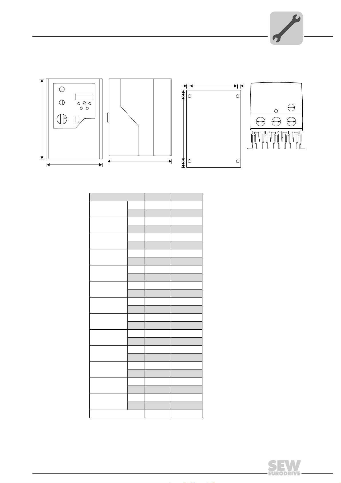
4.1.2 Dimensions of the IP55 / NEMA 12 housing (LTP xxx –10 and –20)
Dimensions
4
b
c
d
B
60198AXX 60200AXX 60199AXX 60497AXX
Dimension Size 1 Size 2
Height (A) [mm] 200 310
Width (B) [mm] 140 165
Depth (C) [mm] 165 176
Weight [kg] 2.3 4.5
a [mm] 128 153
b [mm] 6 6
c [mm] 25 25
d [mm] 142 252
X [mm] 22 25
1)
Y
1)
Z
Power terminal
torque settings
Control terminal
torque settings
Fixings 2 × M4 4 × M4
1) Glands Y and Z are flip out glands.
C
[in] 7.9 12.2
[in] 5.5 6.5
[in] 6.5 6.9
[lb] 5.1 9.9
[in] 5 6
[in] 0.23 0.23
[in] 0.98 0.98
[in] 5.6 9.9
[in] 0.87 0.98
[mm] 22 22
[in] 0.87 0.87
[mm] 17 17
[in] 0.67 0.67
[Nm] 1 1
[lb.in] 8.85 8.85
[Nm] 0.5 0.5
[lb.in] 4.43 4.43
c
a
b
Z
XX
Y
Operating Instructions – MOVITRAC® LTP
13
4
A
Mechanical Installation
IP20 / NEMA 1 housing: mounting and dimensions
4.2 IP20 / NEMA 1 housing: mounting and dimensions
For applications that require a higher IP rating than the IP20 offered by the standard
drive, the drive must be mounted in housing. The following guidelines should be
observed for these applications:
• Housing should be made from a thermally conductive material, unless forced ventilation is used.
• When vented housing is used, there should be venting above and below the drive to
ensure good air circulation. Air should be drawn in below the drive and expelled
above the drive.
• If the external environment contains contamination particles (e.g. dust), a suitable
particle filter should be fitted to the vents and forced ventilation implemented. The
filter must be serviced and cleaned appropriately.
• High moisture, salt or chemical content environments should use a suitably sealed
(non-vented) housing.
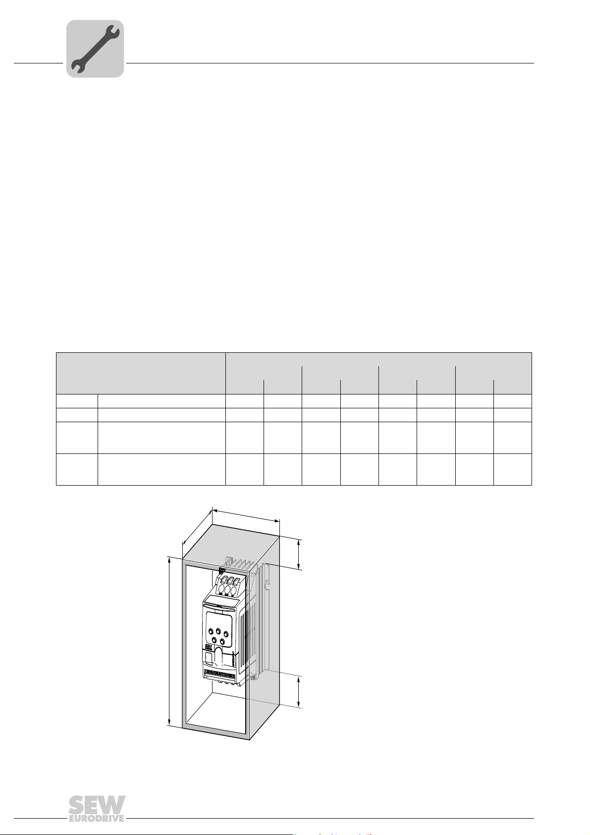
4.2.1 Dimensions of non-vented metal housing
Sealed housing
Drive power rating
Size 1 0.75 kW 230 V 300 11.81 250 9.84 200 7.87 50 1.97
Size 1 1.5 kW 230 V 400 15.75 300 11.81 250 9.84 75 2.95
Size 2 1.5 kW 230 V
0.75 kW, 1.5 kW, 2.2 kW 400 V
2.2 kW 400 V
Size 2 2.2 kW 230 V
4.0 kW 400 V
5.5 kW 575 V
C
A B C D
[mm] [in] [mm] [in] [mm] [in] [mm] [in]
400 15.75 300 11.81 300 11.81 60 2.36
600 23.62 450 17.72 300 11.81 100 3.94
B
D
D
Figure 1: Housing
14
54784AXX
Operating Instructions – MOVITRAC® LTP
IP20 / NEMA 1 housing: mounting and dimensions
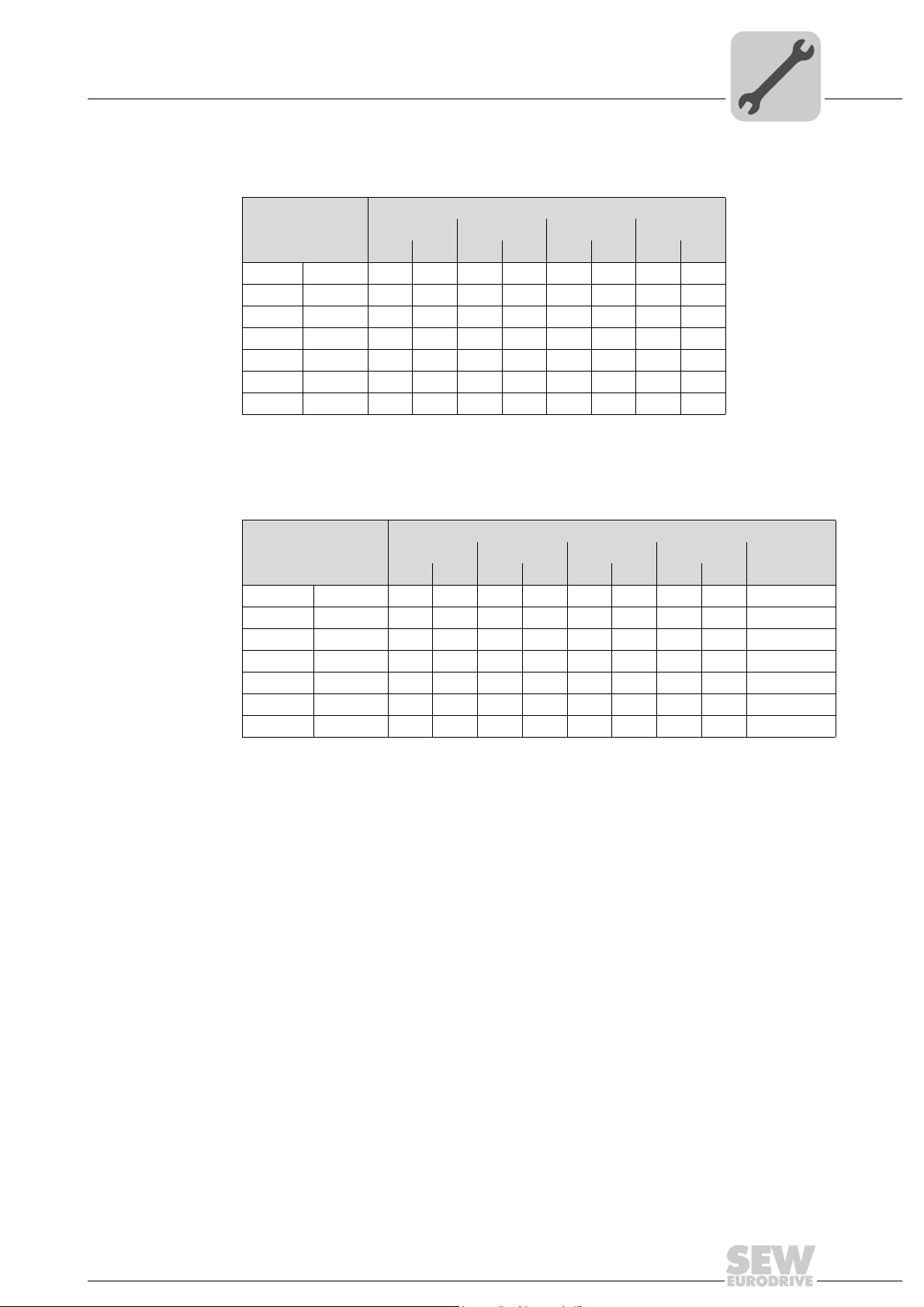
4.2.2 Dimensions of vented housing
Drive power rating
[mm] [in] [mm] [in] [mm] [in] [mm] [in]
Size 1 1.5 kW 400 15.75 300 11.81 150 5.91 75 2.95
Size 2 5.5 kW 600 23.62 400 15.75 250 9.84 100 3.94
Size 3 15 kW 800 31.50 600 23.62 300 11.81 150 5.91
Size 4 22 kW 1000 39.37 600 23.62 300 11.81 200 7.87
Size 437 kW ––––––––
Size 590 kW ––––––––
Size 6160 kW––––––––
4.2.3 Dimensions of force vented housing
Mechanical Installation
Vented housing
A B C D
4
Force vented housing (with fan)
Drive power rating
Size 1 1.5 kW 275 10.83 150 5.91 150 5.91 50 1.97 > 15 m
Size 2 5.5 kW 320 12.60 200 7.87 250 9.84 75 2.95 > 45 m
Size 3 15 kW 400 15.75 250 9.84 250 9.84 100 3.94 > 80 m
Size 4 22 kW 800 31.50 500 19.69 300 11.81 130 5.12 > 300 m
Size 4 37 kW 800 31.50 500 19.69 300 11.81 130 5.12 > 300 m
Size 5 90 kW 1500 59.06 600 23.62 400 15.75 200 7.87 > 900 m
Size 6 160 kW 1600 62.99 600 23.62 400 15.75 250 9.84 > 1000 m
A B C D
Air Flow[mm] [in] [mm] [in] [mm] [in] [mm] [in]
3
/ h
3
/ h
3
/ h
3
/ h
3
/ h
3
/ h
3
/ h
Operating Instructions – MOVITRAC® LTP
15
5
Electrical Installation
Prior to installation
5 Electrical Installation
It is essential to comply with the safety instructions in chapter 2 during installation.
Danger of electrical shock. High voltages are present in the terminals and in within the
drive for up to 10 minutes after the electrical supply has been disconnected.
Severe or fatal injuries.
• Disconnect and isolate the MOVITRAC
10 minutes before commencing any work on it.
•MOVITRAC
accordance with local and national regulations and codes of practice.
• The MOVITRAC
use a suitable enclosure or the IP55 version.
• Where the electrical supply to the drive is through a plug and socket connector, do
not disconnect until 10 minutes have elapsed after turning off the supply.
• Ensure correct earthing connections. See diagram in chapter "Drive and motor
connection" on page 20.
• The earth cable must be sufficient to carry the maximum supply fault current which
normally will be limited by the fuses or motor circuit breaker.
WARNING
®
LTP units should only be installed by qualified electricians and in
®
LTP from the electrical supply at least
®
LTP has an Ingress Protection rating of IP20. For higher IP ratings,
HAZARD
Risk of fatal injury if the hoist falls.
Severe or fatal injuries.
•MOVITRAC
Use monitoring systems or mechanical protection devices to ensure safety.
5.1 Prior to installation
• Ensure that the supply voltage, frequency and number of phases (single or 3-phase)
correspond to the rating of the MOVITRAC
• An isolator or similar should be installed between the power supply and the drive.
• Never connect the mains power supply to the MOVITRAC
U, V or W.
• When installing 575 V inverters ensure the motor is always in STAR connection.
• The cables are only protected when slow blow HRC fuses or a motor circuit breaker
(MCB) are used.
• Do not install any type of automatic switchgear between the drive and the motor.
Wherever control cabling is close to power cabling, maintain a minimum separation
of 100 mm and arrange crossings at 90 °.
• Ensure that screening or armoring of power cables is effected in accordance with the
connections diagram in chapter "Drive and motor connection" on page 20.
• Ensure that all terminals are tightened to the appropriate torque.
®
LTP is not designed for use as a safety device in hoist applications.
®
LTP as delivered.
®
LTP output terminals
16
Operating Instructions – MOVITRAC® LTP

Electrical Installation
Prior to installation
5.1.1 Opening the front cover
IP55 size 1 & 2 Insert a screwdriver into the opening as illustrated below to release the front cover.
Z
XX
Y
64506AXX
5.1.2 Helpcard
In the IP20 housing the helpcard is located in a separate slot above the display. In the
IP55 housing the helpcard is attached to the inside of the front cover.
5
Operating Instructions – MOVITRAC® LTP
17
5
Electrical Installation
Installation
5.2 Installation
Connect the drive according to the following diagram. Ensure that the motor terminal box
connections are correct. There are two standards in general: Star and Delta. It is essential to ensure that the motor is connected in accordance with the voltage at which it will
be operated. For more information, refer to the diagram below.
Please refer to chapter 10 for the recommended cabling and wiring sizing.
It is recommended that the power cabling should be 4-core PVC-insulated screened
cable, laid in accordance with local industrial regulations and codes of practice.
The ground terminal of each MOVITRAC
directly to the site earth (ground) busbar (through the filter if installed) as shown.
MOVITRAC
should also not loop to or from any other equipment. Ground loop impedance must
conform to local industrial safety regulations. To meet UL regulations, UL approved ring
crimp terminals should be used for all earth wiring connections.
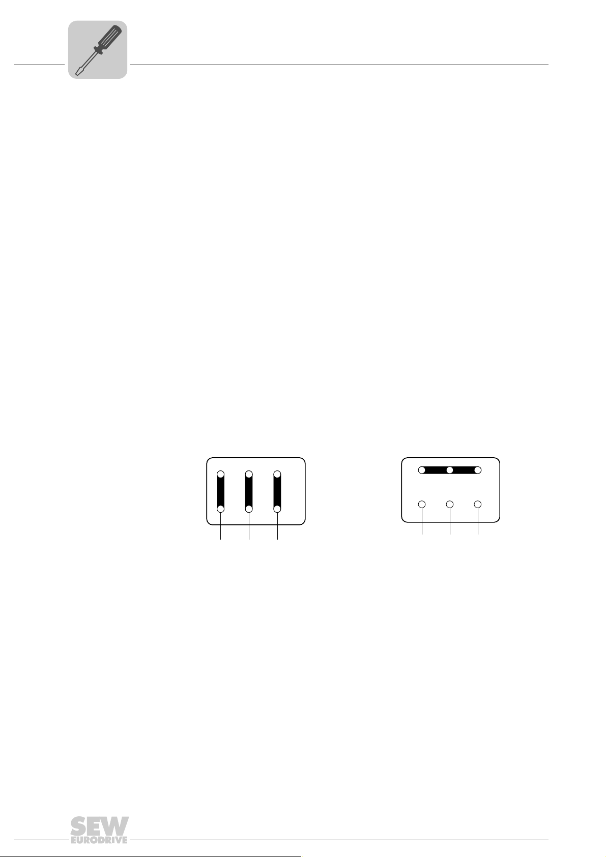
5.2.1 Motor terminal box connections
®
LTP should be individually connected
®
LTP ground connections should not loop from one drive to another. They
Motors are connected in either Star, Delta, Double Star or Star Nema motors. The motor
rating plate indicates the voltage rating for the method of connection, which must match
the operating voltage of the MOVITRAC
R13
U2
W2
V2
®
LTP unit.
W2 U2
V2
U1UV1 W1
U1UV1
V W
Low voltage Δ High voltage 댴
W1
V W
18
Operating Instructions – MOVITRAC® LTP
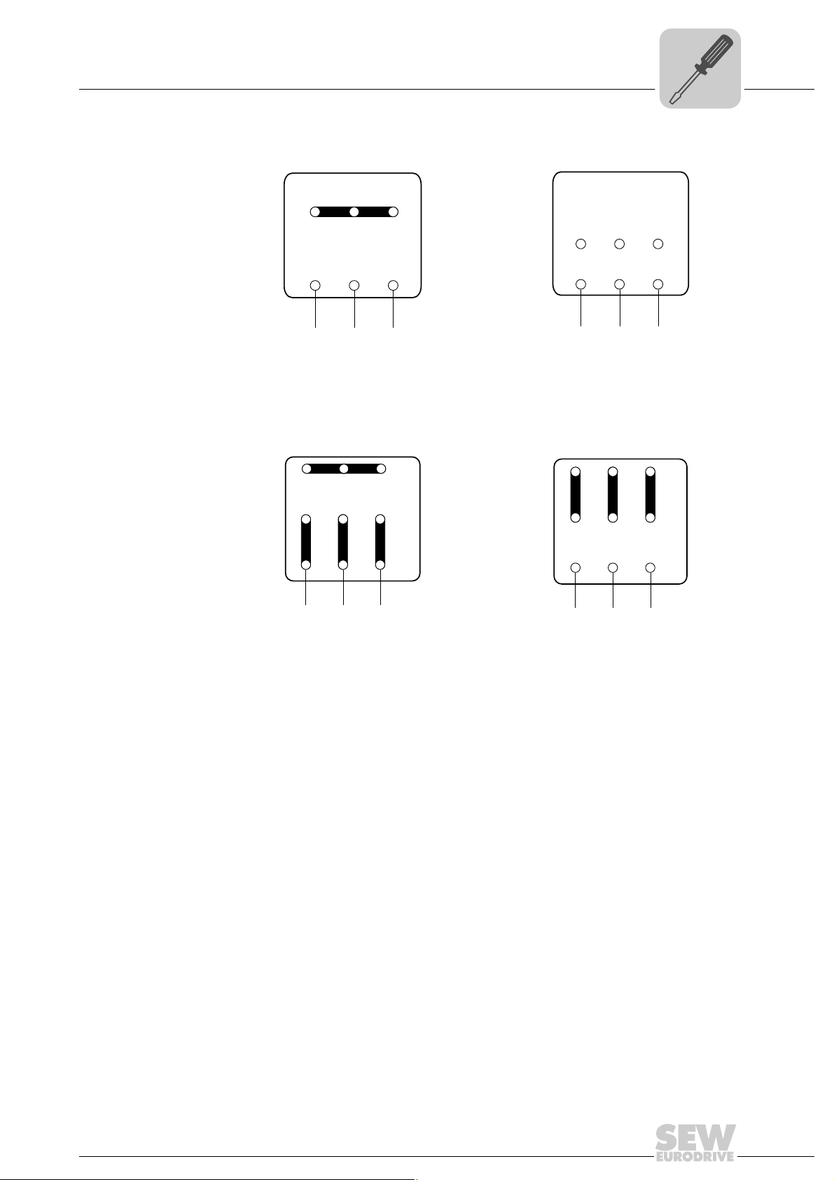
R76
Electrical Installation
Installation
5
DT / DV
T6 T4 T5
W2 U2 V2
T6 T4 T5
W2 U2 V2
T9 T7
T9 T7 T8
U3 V3
W3
T1 T2 T3
V1 W1
U1
L1
L2 L1
Low voltage 댴댴 High voltage 댴
W3 U3 V3
T1 T2 T3
U1L1V1 W1
L2 L1
T4 T5 T6
T4 T5 T6
U2 V2 W2
T7 T8
V3
U3
T1 T2
U1
V1
T9
W3
T3
W1
U2 V2 W2
T7 T8 T9
V3
U3
T1 T2 T3
V1
U1
T8
W3
W1
U
V W
Low voltage 댴댴 High voltage 댴
U
V W
Operating Instructions – MOVITRAC® LTP
19
5
Electrical Installation
Installation
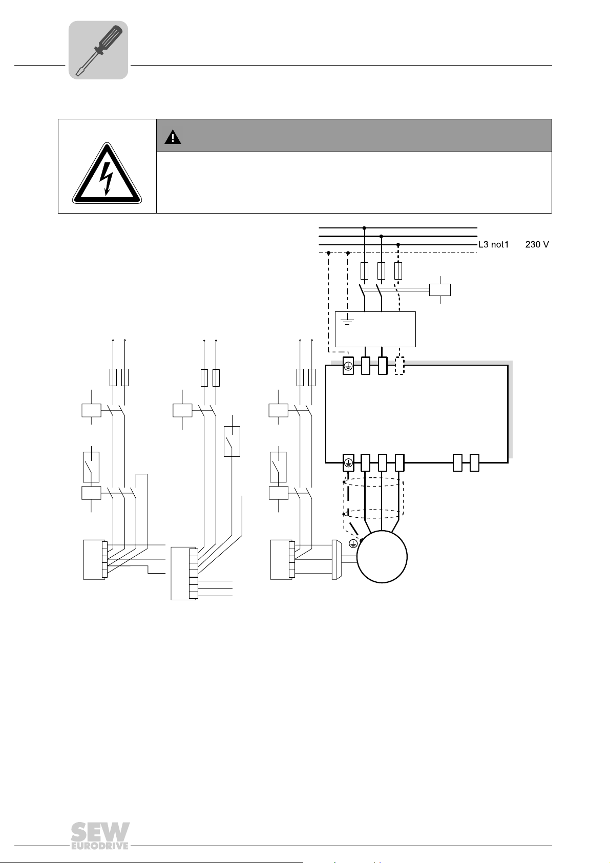
5.2.2 Drive and motor connection
Danger of electrical shock. Risk of exposure to high voltage may occur if the unit is
wired incorrectly.
Severe or fatal injuries.
• It is essential to observe the connection sequence illustrated below.
WARNING
L1
L2/N
-ph.
PE
F11/F12/F13
F14/F15
V
AC
V
AC
[2]
red
white
blue
+V
10
11
GND
K11
(AC-3)
K11
(AC-3)
[V+] +V
10
11
[4]
K12
(AC-3)
*
[3]
1
2
BG
3
BGE
4
5
DT/DV/D: DT/DV/D:
Cut-off in the DC
and AC circuits
white
red
blue
BMK
1
2
3
4
13
14
15
Figure 2: Wiring diagram for power section
K11
(AC-3)
K12
(AC-3)
GNDGND
V
AC
F14/F15F14/F15
10
11
white
1
2
BG
3
BGE
4
5
Cut-off in the AC
circuit
L1 L2
Option ND.. input choke
L1' L2'
L1 L2 L3
UVW
red
blue
3-phase
L3
L3'
Power section
M
BW
K10
[1]
(AC-3)
BR
+
BW.. / BW..-T
braking resistor
connection*
64606AEN
20
[1] Mains supply contactor to drive
[2] Mains supply to brake rectifier, switched simultaneously by K10
[3] Control contactor / relay, energized via the internal relay contact [4] in the drive and supplies the brake rectifier
[4] Potential free relay contact inside the drive
[V+] External power supply for energizing the control contactor / relay
* Size 2 an
d above
Operating Instructions – MOVITRAC® LTP

Electrical Installation
Installation
NOTE
• Connect the brake rectifier using a separate supply system lead.
• Supply via the motor voltage is not permitted!
The 230 V and 400 V drives do not require a line choke on the supply unless the specified supply voltages cannot be guaranteed.
Drives from 0.37 kW (0.5 HP) to 5.5 kW (7.5 HP) must be fitted with external line chokes
if the quality of the supply cannot be guaranteed.
An external line choke is always required for 575 V drives from 0.75 kW (1 HP) to 5.5 kW
(7.5 HP).
All drives with 7.5 kW (10 HP) or greater have a built-in choke and therefore do not need
external chokes fitted to ensure transient protection.
An external choke is required if 230 V or 400 V drives up to 5.5 kW (7.5 HP) are installed
under the following conditions:
• Local generator
• Large loads on the same supply
• High dV / dt voltage fluctuations e.g. when welders are being used
• Outdoor pumping stations with exposed supply lines, which may be hit by lightening
strikes.
Always switch off the brake on the DC and AC sides with:
• All hoist applications
• Drives that require a rapid brake response time
5
It is essential to adhere to the connection sequence of the brake connector. Incorrect
connection will lead to irreparable damage to the brake. The connection to the brake
rectifier requires a separate supply system cable. Supply from the motor voltage is not
permitted.
If the brake rectifier is installed in the switch cabinet the connecting cable between the
brake rectifier and the brake must be routed separately to other power cables. Routing
together with other cables is only permitted if the other cables are shielded. Set P2-13
to 3 to use the relay output to control the brake rectifier (BGx).
5.2.3 Motor thermal protection (TF / TH)
Motors with an internal PTC over-temperature sensor (TF, TH or similar) can be connected directly to the MOVITRAC
The sensor is connected to terminal 1 (+24 V) and Digital Input 3. Parameter P2-01 must
be set to external trip input to receive over-temperature trips. The trip level should be set
to 2.5 k
Ω.
®
LTP. A trip will then be displayed on the drive.
Operating Instructions – MOVITRAC® LTP
21
5
Electrical Installation
Installation
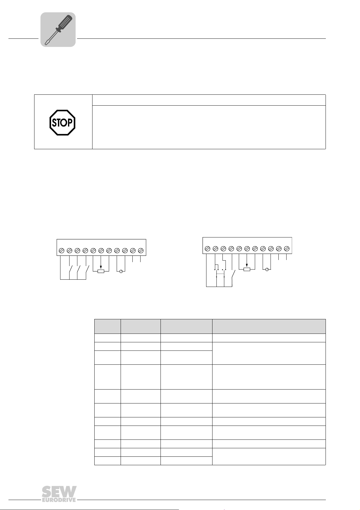
5.2.4 Signal terminal overview
IP20 and IP55 IP55 with switch option
The User Control terminals are available via an 11-way pluggable connector. All terminals are galvanically isolated, allowing direct connection to other equipment.
STOP!
Danger of damage to the MOVITRAC® LTP unit.
Do not connect mains supply voltages to any terminals other than the user relay output.
Doing so will result in permanent damage to the unit.
The user relay output can handle up to AC 250 V. All other inputs only withstand
DC 30 V without damage.
The functionality of the inputs and outputs is user configurable. All operating modes are
set up via the parameter set.
Up to 100 mA can be sourced from the User +24 V output and up to 20 mA from the
analog output.
+24 V
DI 1
DI 2
DI 3
+10 V
AI/DI
0 V
AO/DO
0 V
Relay contact
Relay common
1 234567891011
64485AEN 64608AEN
The signal terminal block has the following signal connections:
Ter minal
no.
10 Relay contact Relay contact N.O. relay contact (AC 250 V / DC 30 V @ 5 A)
11 Relay common Relay common
Signal Connection Description
1 +24 V +24 V ref out Ref. to activate DI1 ... DI3 (100 mA max.)
2 DI1 Digital input 1 Positive logic
3 DI2 / DO2 Digital input 2 /
4 DI3 / AI2 Digital input 3 /
5 +10 V +10 V ref out 24 V ref for analog input
6 AI / DI Analog input (12 bit)
7 0 V 0 V common 0 V ref for analog input (pot supply –)
8 AO / DO Analog output (8 bit)
9 0 V 0 V common 0 V ref for analog output
Digital output 2
Analog input 2
Digital input 4
Digital output
+24 V
DI 1
DI 2
DI 3
+10 V
AI/DI
0 V
AO/DO
0 V
Relay contact
Relay common
1 234567891011
FWD
REV
"Logic 1" in
"Logic 0" in
Positive logic (P2-33)
"Logic 1" in
"Logic 0" input voltage range: DC 0... 8 V
0 ... 10 V, 0 ... 20 mA, 4 ... 20 mA
(pot supply +, 100 mA max., 1 k Ω min.)
0 ... 10 V, –10 ... 10 V, 0 ... 24 V, –24 ... 24 V
"Logic 1" input voltage range: DC 8 ... 30 V (P2-30)
0 ... 10 V, 4 ... 20 mA analog
24 V, 20 mA digital (P2-36)
put voltage range: DC 8... 30 V
put voltage range: DC 0... 8 V
put voltage range: DC 8... 30 V
22
Operating Instructions – MOVITRAC® LTP
Key information on the control terminal
• Maximum input voltage on any terminal: DC 30 V
• All outputs are short circuit proof
• Recommended potentiometer resistance: 1 k
• Digital input response time < 8 ms
• Bipolar analog input response time < 16 ms. Resolution ±12-bit (0.025 %)
• Second analog input response time < 16ms. Resolution +11-bit (0.05 %)
• Analog / digital output response time < 16ms. Resolution 8-bit (0.25 %)
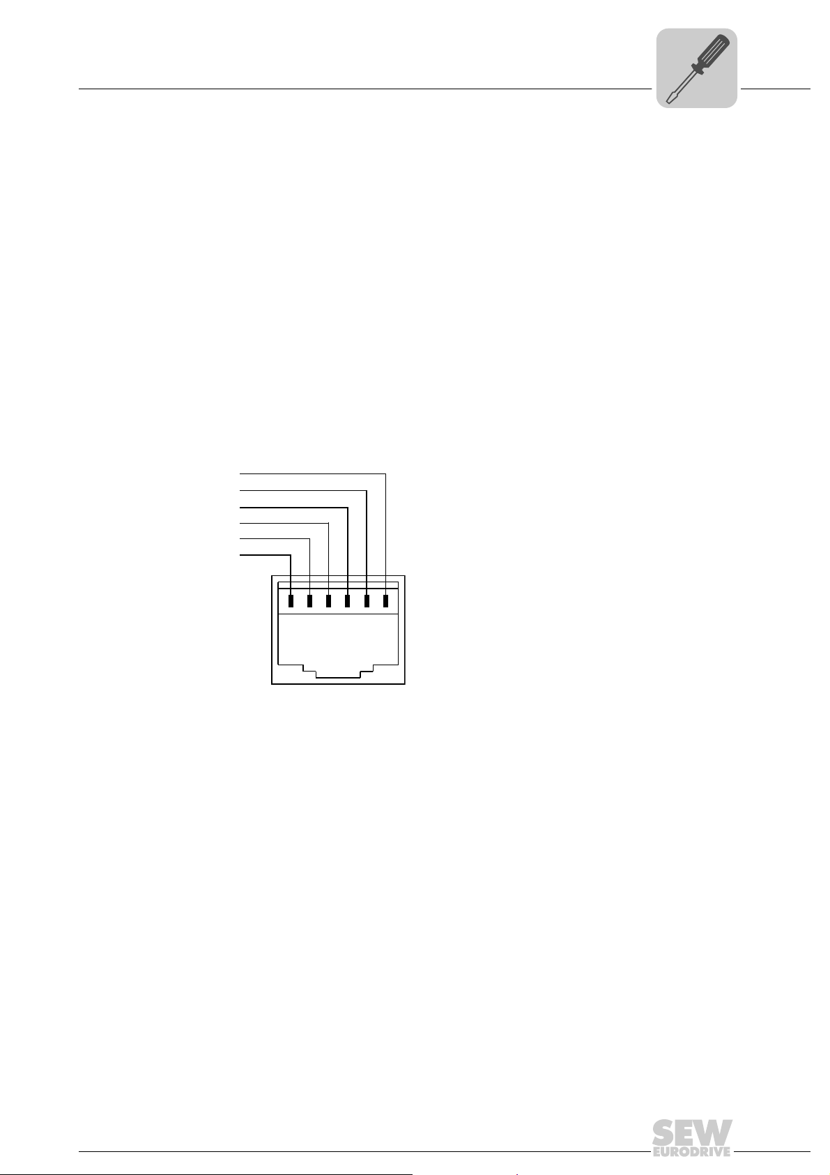
5.2.5 RJ11 Communication socket
The RJ11 communication socket can be used to set up a RS-485 communication to the
PC via UWS11A.
With MOVITRAC
MODBUS communication network.
Electrical Installation
Installation
Ω
®
LTP units it is possible to use this RJ11 connector to set up a
5
[1]
[2]
[3]
[4]
[5]
[6]
57406AXX
[1] RS-485– / MODBUS 1)
[2] RS-485+ / internal bus
[3] RS-485– / internal bus
[4] +24 V
[5] 0 V
[6] RS-485+ / MODBUS
1) The bit format is fixed as: 1 start bit, 8 data bits, 1 stop bit, no parity
1)
1)
1)
The internal bus works with 115 k Baud (bps). It can be used for drive-to-drive communication. In this case, up to 63 drives can communicate.
The MODBUS RTU works between 9,6 and 115 k Baud (bps). It can be used to communicate directly with an external PLC or with a fieldbus gateway. In this case, up to 63
drives can be controlled via bus communication.
Operating Instructions – MOVITRAC® LTP
23
5
Electrical Installation
Optical interface
5.3 Optical interface
The optical interface, which is located next to the RJ11 connector, is mainly used for
commissioning and monitoring the drive with a pocket PC. When LTP shell CE is
installed, the pocket PC can be used to commission the drive and monitor the current
status of the drive.
5.4 UL-compliant installation
Note the following for UL-compliant installation:
• The drives can be operated within an ambient temperature of 0 ... 50 °C.
• Only use copper connection cables which can withstand ambient temperatures of up
to 75 °C.
• Permitted tightening torques for MOVITRAC
– Sizes 1, 2 & 3 = 1 Nm / 8.9 lb.in
– Size 4 = 4 Nm / 35.4 lb.in
– Sizes 5 & 6 = 8 Nm / 70 lb.in
®
LTP power terminals are:
®
MOVITRAC
LTP drive inverters are suitable for operation in voltage power systems
with an earthed star point (TN and TT systems), which can supply a maximum supply
current and a maximum supply voltage in accordance with the following table. The fuses
listed in the following tables are the maximum permitted fuses for each inverter. Only
use melting fuses.
Only use tested units with a limited output voltage (V
= DC 30 V) and limited output
max
current (I = < 8 A) as an external DC 24 V source.
UL certification does not apply to operation in voltage supply systems with a non-earthed
star point (IT systems).
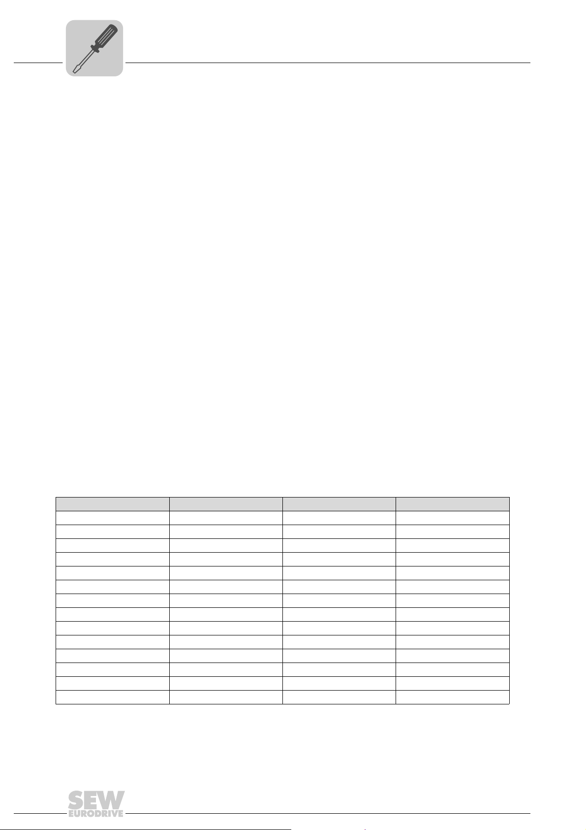
5.4.1 200 ... 240 V Units
MOVITRAC® LTP... Short circuit rating Max. supply voltage Fuses
0004 AC 5000 A AC 240 V AC 6 A / 250 V
0008 AC 5000 A AC 240 V AC 10A / 250 V
0015 AC 5000 A AC 240 V AC 20A / 250 V
0030, 0040, 022 AC 5000 A AC 240 V AC 32 A / 250 V
0055 AC 5000 A AC 240 V AC 50 A / 250 V
0075 AC 5000 A AC 240 V AC 80 A / 250 V
0110, 0150 AC 5000 A AC 240 V AC 100 A / 250 V
0185 AC 5000 A AC 240 V AC 125 A / 250 V
0220 AC 10000 A AC 240 V AC 160 A / 250 V
0300 AC 10000 A AC 240 V AC 200 A / 250 V
0370, 0450 AC 10000 A AC 240 V AC 300 A / 250 V
0550 AC 10000 A AC 240 V AC 350 A / 250 V
0750 AC 10000 A AC 240 V AC 400 A / 250 V
0900 AC 10000 A AC 240 V AC 500 A / 250 V
24
Operating Instructions – MOVITRAC® LTP
 Loading...