

SEW MOVITRAC LTP-B Operating Instruction
Drive Technology \ Drive Automation \ System Integration \ Services
Operating Instructions
*22872051_0916*
Standard Inverters
MOVITRAC® LTP-B
Edition 09/2016 22872051/EN

SEW-EURODRIVE—Driving the world

Table of contents
Table of contents
1 General information.................................................................................................................. 8
1.1 About this documentation ...............................................................................................8
1.2 Structure of the safety notes ...........................................................................................8
1.2.1 Meaning of signal words ................................................................................ 8
1.2.2 Structure of section-related safety notes........................................................ 8
1.2.3 Structure of embedded safety notes .............................................................. 8
1.3 Rights to claim under limited warranty ............................................................................9
1.4 Content of the documentation.........................................................................................9
1.5 Exclusion of liability.........................................................................................................9
1.6 Product names and trademarks......................................................................................9
1.7 Copyright notice ..............................................................................................................9
2 Safety notes ............................................................................................................................ 10
2.1 Preliminary information .................................................................................................10
2.2 Operator's duties...........................................................................................................10
2.3 Target group .................................................................................................................10
2.4 Designated use .............................................................................................................11
2.4.1 Hoist applications ......................................................................................... 11
2.5 Functional safety technology ........................................................................................12
2.6 Transport.......................................................................................................................12
2.7 Installation/assembly.....................................................................................................12
2.7.1 Restrictions of use........................................................................................ 13
2.8 Electrical connection .....................................................................................................13
2.8.1 Required preventive measure ...................................................................... 13
2.8.2 Stationary application................................................................................... 13
2.9 Protective separation ....................................................................................................14
2.10 Startup/operation ..........................................................................................................14
3 Device structure ..................................................................................................................... 15
3.1 Nameplate.....................................................................................................................15
3.2 Type designation...........................................................................................................15
3.3 Device structure of the standard inverter ......................................................................16
4 Installation............................................................................................................................... 19
4.1 General information ......................................................................................................19
4.2 Permitted tightening torques .........................................................................................20
4.3 Mechanical installation..................................................................................................21
4.4 Electrical installation .....................................................................................................23
22872051/EN – 09/2016
3.3.1 Inverters with degree of protection IP20/NEMA 1 ........................................ 16
3.3.2 Inverters with degree of protection IP66/NEMA 4X...................................... 17
3.3.3 Inverters with degree of protection IP55/NEMA 12K.................................... 18
4.3.1 IP20 housing: Installation and installation space ......................................... 21
4.3.2 IP55/IP66 housing: Installation and control cabinet dimensions .................. 22
4.4.1 Before installation......................................................................................... 23
4.4.2 Line contactors............................................................................................. 24
4.4.3 Mains fuses .................................................................................................. 25
Operating Instructions – MOVITRAC® LTP-B
3

Table of contents
4.4.4 Operation on an IT system........................................................................... 26
4.4.5 Operation on a TN system with an RCD switch (IP20) ................................27
4.4.6 Permitted voltage supply systems................................................................ 27
4.4.7 Help card...................................................................................................... 27
4.4.8 Removing the terminal cover ....................................................................... 28
4.4.9 Cable gland plate ......................................................................................... 30
4.4.10 Connecting and installing the braking resistor ............................................. 31
4.4.11 Motor temperature protection TF, TH, KTY84, PT1000 ............................... 32
4.4.12 Multi-motor drive/group drive ....................................................................... 33
4.4.13 Motor cables and fusing ............................................................................... 33
4.4.14 Connecting AC brakemotors ........................................................................ 33
4.4.15 UL-compliant installation .............................................................................. 34
4.4.16 Information regarding UL ............................................................................. 37
4.4.17 Electromagnetic compatibility (EMC) ...........................................................38
4.4.18 Overview of signal terminals ........................................................................44
4.4.19 Communication socket RJ45 ....................................................................... 47
4.4.20 24V backup mode ....................................................................................... 48
4.4.21 DC link connection .......................................................................................49
4.5 Wiring diagram..............................................................................................................49
4.5.1 Brake control ................................................................................................ 51
5 Startup ..................................................................................................................................... 52
5.1 User interface................................................................................................................52
5.1.1 Keypads .......................................................................................................52
5.1.2 Resetting parameters to default settings...................................................... 54
5.1.3 Key combinations......................................................................................... 54
5.1.4 Software LT Shell......................................................................................... 55
5.1.5 MOVITOOLS® MotionStudio engineering software...................................... 57
5.2 Automatic measuring procedure "Auto tune" ...............................................................59
5.3 Startup for motors .........................................................................................................59
5.3.1 Startup for asynchronous motors with V/f control ........................................ 60
5.3.2 Startup for asynchronous motors with VFC speed control........................... 60
5.3.3 Startup for asynchronous motors with VFC torque control .......................... 61
5.3.4 Startup of synchronous motors without encoder feedback (PMVC control).......
62
5.3.5 Startup with LSPM motors from SEW‑EURODRIVE ................................... 63
5.3.6 Startup with preset motors from SEW‑EURODRIVE ...................................64
5.4 Startup of control...........................................................................................................65
5.4.1 Terminal mode (factory setting) P1-12 = 0................................................... 65
5.4.2 Keypad mode (P1-12 = 1 or 2)..................................................................... 66
5.4.3 PID controller mode (P1-12 = 3) .................................................................. 66
5.4.4 Master-slave mode (P1-12 = 4).................................................................... 68
5.4.5 Fieldbus mode (P1-12 = 5, 6 or 7) ............................................................... 69
5.4.6 MultiMotion mode (P1-12 = 8)...................................................................... 69
5.5 Hoist function ................................................................................................................70
5.5.1 General information...................................................................................... 71
5.5.2 Startup for hoist function .............................................................................. 71
22872051/EN – 09/2016
Operating Instructions – MOVITRAC® LTP-B
4

Table of contents
5.5.3 Hoisting mode ..............................................................................................72
5.5.4 Troubleshooting and optimizing the hoist function ....................................... 73
5.6 Fire mode/emergency mode .........................................................................................74
5.7 Operation at 87 Hz characteristic..................................................................................75
5.8 Motor potentiometer function – crane application.........................................................75
5.8.1 Motor potentiometer operation ..................................................................... 76
5.8.2 Terminal assignment.................................................................................... 77
5.8.3 Parameter settings ....................................................................................... 77
5.9 Examples of analog input scaling and offset setting.....................................................78
5.9.1 Example 1: Analog input scaling .................................................................. 78
5.9.2 Example 2: Analog input offset .................................................................... 79
5.9.3 Example 3: Analog input scaling and offset ................................................. 80
5.10 Fans and pumps ...........................................................................................................81
5.11 Motor potentiometer......................................................................................................81
5.12 3-wire control ................................................................................................................82
5.12.1 Control signal source 3-wire control............................................................. 82
6 Operation................................................................................................................................. 83
6.1 Inverter status ...............................................................................................................83
6.2 Troubleshooting ............................................................................................................86
6.3 Error history ..................................................................................................................86
6.4 Error codes ...................................................................................................................87
7 Fieldbus mode ........................................................................................................................ 92
7.1 General information ......................................................................................................92
7.2 Connecting a gateway or controller (SBusMOVILINK®)..............................................96
7.3 Modbus RTU.................................................................................................................99
22872051/EN – 09/2016
7.4 CANopen ....................................................................................................................103
6.1.1 Static inverter status..................................................................................... 83
6.1.2 Operating state of the inverter...................................................................... 84
6.1.3 Status displays of the parameter module..................................................... 85
6.1.4 Fault reset ....................................................................................................85
7.1.1 Structure and settings of process data words .............................................. 92
7.1.2 Communication example.............................................................................. 94
7.1.3 Parameter settings for the inverter............................................................... 94
7.1.4 Connecting the signal terminals at the inverter ............................................ 95
7.1.5 Establishing a CANopen/SBus network ....................................................... 95
7.2.1 Specification................................................................................................. 96
7.2.2 Electrical installation..................................................................................... 96
7.2.3 Startup at gateway ....................................................................................... 97
7.2.4 Startup at a CCU.......................................................................................... 98
7.2.5 MOVI‑PLC® motion protocol (P1-12 = 8)...................................................... 98
7.3.1 Specification................................................................................................. 99
7.3.2 Electrical installation..................................................................................... 99
7.3.3 Register allocation of the process data words ........................................... 100
7.3.4 Data flow example...................................................................................... 101
7.4.1 Specification............................................................................................... 103
Operating Instructions – MOVITRAC® LTP-B
5

Table of contents
7.4.2 Electrical installation................................................................................... 103
7.4.3 COB IDs and functions in the inverter........................................................ 103
7.4.4 Supported transmission modes.................................................................. 104
7.4.5 Default allocation plan of process data objects (PDO)............................... 104
7.4.6 Data flow example...................................................................................... 105
7.4.7 Table of CANopen-specific objects ............................................................ 106
7.4.8 Table of manufacturer-specific objects ...................................................... 108
7.4.9 Emergency code objects............................................................................ 108
8 Service................................................................................................................................... 109
8.1 Electronics Service by SEW‑EURODRIVE.................................................................109
8.2 Extended storage........................................................................................................109
8.3 Waste disposal............................................................................................................110
9 Parameters ............................................................................................................................ 111
9.1 Overview of parameters..............................................................................................111
9.1.1 Parameters for realtime monitoring (read only).......................................... 111
9.1.2 Parameter register ..................................................................................... 116
9.2 Explanation of the parameters ....................................................................................122
9.2.1 Parameter group 1: Basic parameters (level 1) ......................................... 122
9.2.2 Parameter group 1: Servo-specific parameters (level 1)............................ 130
9.2.3 Parameter group 2: Extended parameter setting (level 2) ......................... 132
9.2.4 Parameter group 3: PID controller (level 2)................................................ 142
9.2.5 Parameter group 4: Motor control (level 2) ................................................ 145
9.2.6 Parameter group 5: Fieldbus communication (level 2)............................... 151
9.2.7 Parameter group 6: Extended parameters (level 3) ................................... 155
9.2.8 Parameter group 7: Motor control parameters (level 3) ............................. 161
9.2.9 Parameter group 8: Application-specific parameters (only LTX) (level 3).. 164
9.2.10 Parameter group 9: Digital inputs defined by the user (level 3) ................. 166
10 Technical data....................................................................................................................... 173
10.1 Markings .....................................................................................................................173
10.2 Ambient conditions......................................................................................................174
10.3 Technical data.............................................................................................................175
10.3.1 1-phase system AC 200 – 240V ............................................................... 175
10.3.2 3-phase system AC 200 – 240V ............................................................... 176
10.3.3 3-phase system AC 380 – 480V ............................................................... 180
10.3.4 3-phase system AC 500 – 600V ............................................................... 184
10.4 Input voltage ranges ...................................................................................................187
10.5 Overload capacity .......................................................................................................187
10.6 Housing variants and dimensions...............................................................................188
10.6.1 Housing variants ........................................................................................ 188
10.6.2 Dimensions ................................................................................................ 189
10.6.3 Dimensions ................................................................................................ 190
10.7 Protection function ......................................................................................................192
11 Functional safety (STO) ....................................................................................................... 193
11.1 Integrated safety technology.......................................................................................193
22872051/EN – 09/2016
Operating Instructions – MOVITRAC® LTP-B
6

Table of contents
11.1.1 Safe condition ............................................................................................ 193
11.1.2 Safety concept ........................................................................................... 193
11.1.3 Restrictions ................................................................................................ 196
11.2 Safety conditions.........................................................................................................197
11.2.1 Storage requirements................................................................................. 197
11.2.2 Installation requirements ............................................................................ 197
11.2.3 Requirements on the external safety controller.......................................... 199
11.2.4 Requirements for safety relays .................................................................. 200
11.2.5 Requirements on startup............................................................................ 200
11.2.6 Requirements on operation........................................................................ 200
11.3 Connection variants ....................................................................................................202
11.3.1 General information.................................................................................... 202
11.3.2 Disconnection of a single drive .................................................................. 203
11.4 Safety characteristics..................................................................................................206
11.5 Signal terminal block for STO safety contact..............................................................206
12 Declaration of conformity .................................................................................................... 207
Index ...................................................................................................................................... 208
13 Address list ........................................................................................................................... 214
22872051/EN – 09/2016
Operating Instructions – MOVITRAC® LTP-B
7
General information
1
About this documentation
1 General information
1.1 About this documentation
This documentation is an integral part of the product. The documentation is written for
all employees who assemble, install, start up, and service this product.
Make sure this documentation is accessible and legible. Ensure that persons responsible for the machinery and its operation as well as persons who work on the product
independently have read through the documentation carefully and understood it. If you
are unclear about any of the information in this documentation or require further information, contact SEW‑EURODRIVE.
1.2 Structure of the safety notes
1.2.1 Meaning of signal words
The following table shows the grading and meaning of the signal words for safety
notes.
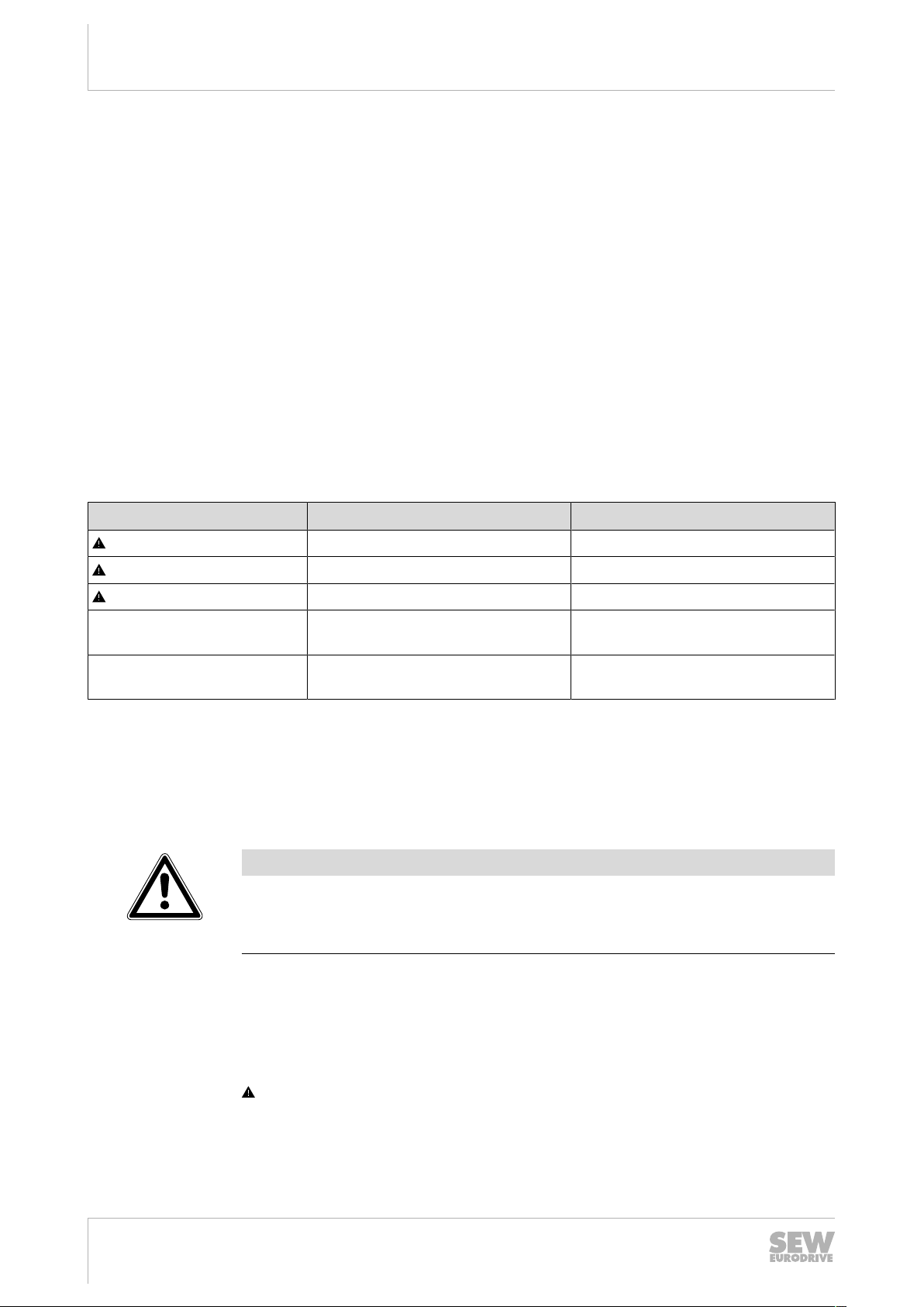
Signal word Meaning Consequences if disregarded
DANGER Imminent hazard Severe or fatal injuries.
WARNING Possible dangerous situation Severe or fatal injuries.
CAUTION Possible dangerous situation Minor injuries
NOTICE Possible damage to property Damage to the drive system or its
environment.
INFORMATION Useful information or tip: Simplifies
handling of the drive system.
1.2.2 Structure of section-related safety notes
Section-related safety notes do not apply to a specific action but to several actions
pertaining to one subject. The hazard symbols used either indicate a general hazard
or a specific hazard.
This is the formal structure of a safety note for a specific section:
SIGNAL WORD
Type and source of hazard.
Possible consequence(s) if disregarded.
• Measure(s) to prevent the hazard.
1.2.3 Structure of embedded safety notes
Embedded safety notes are directly integrated into the instructions just before the description of the dangerous action.
This is the formal structure of an embedded safety note:
SIGNAL WORD Type and source of hazard. Possible consequence(s) if disreg-
arded. Measure(s) to prevent the hazard.
Operating Instructions – MOVITRAC® LTP-B
8
22872051/EN – 09/2016

1.3 Rights to claim under limited warranty
Read the information in this documentation. This is essential for fault-free operation
and fulfillment of any rights to claim under limited warranty. Read the documentation
before you start working with the product.
1.4 Content of the documentation
The current version of the operating instructions is the original.
This document contains additional safety-relevant information and conditions for use
in safety-related applications.
1.5 Exclusion of liability
Read the information in this documentation, otherwise safe operation is impossible.
You must comply with the information contained in this documentation to achieve the
specified product characteristics and performance features. SEW‑EURODRIVE assumes no liability for injury to persons or damage to equipment or property resulting
from non-observance of these operating instructions. In such cases,
SEW‑EURODRIVE assumes no liability for defects.
General information
Rights to claim under limited warranty
1
1.6 Product names and trademarks
The brands and product names in this documentation are trademarks or registered
trademarks of their respective titleholders.
1.7 Copyright notice
©2016SEW‑EURODRIVE. All rights reserved. Unauthorized reproduction, modification, distribution or any other use of the whole or any part of this documentation is
strictly prohibited.
22872051/EN – 09/2016
Operating Instructions – MOVITRAC® LTP-B
9

Safety notes
2
Preliminary information
2 Safety notes
2.1 Preliminary information
The following general safety notes have the purpose to avoid injury and damage to
property. They primarily apply to the use of products described in this documentation.
If you use additional components also observe the relevant warning and safety notes.
2.2 Operator's duties
Make sure that the basic safety notes are read and observed. Make sure that persons
responsible for the machinery and its operation as well as persons who work on the
device independently have read through the documentation carefully and understood
it. If you are unclear about any of the information in this documentation, or if you require further information, contact SEW‑EURODRIVE.
The operator must ensure that the following works are only performed by qualified personnel:
• Transport
• Storage
• Setup and assembly
• Installation and connection
• Startup
• Maintenance and repair
• Shutdown
• Disassembly
• Waste disposal
Make sure persons working on the product adhere to the following regulations, re-
quirements, documents and information:
• National and regional safety and accident prevention regulations
• Warning and safety signs on the product
• All other relevant project planning documents, installation and startup instructions,
wiring diagrams and schematics
• Do not assemble, install or operate damaged products
• All specific specifications and requirements for the system
Make sure that systems with the product installed are equipped with additional monitoring and protection devices. Observe the applicable safety regulations and legislation governing technical equipment and accident prevention regulations.
2.3 Target group
Specialist for
mechanical work
10
Operating Instructions – MOVITRAC® LTP-B
Any mechanical work may only be performed by adequately qualified personnel. Qualified personnel in the context of this documentation are persons familiar with the
design, mechanical installation, troubleshooting and maintenance of the product, who
possess the following qualifications:
• Qualification in the field of mechanics according to applicable national regulation.
• They are familiar with this documentation
22872051/EN – 09/2016

Safety notes
Designated use
2
Specialist for electrotechnical work
Instructed persons All work in the areas of transportation, storage, operation and waste disposal must be
Any electronic work may only be performed by adequately skilled persons (electrically). Qualified electricians in the context of this documentation are persons familiar
with electrical installation, startup, troubleshooting and servicing of the product who
possess the following qualifications:
• Qualification in the field of electrical engineering according to applicable national
regulation.
• They are familiar with this documentation
In addition to that, these persons must be familiar with the valid safety regulations and
laws, as well as with the requirements of the standards, directives and laws specified
in this documentation. The above mentioned persons must have the authorization expressly issued by the company to operate, program, configure, label and ground
devices, systems and circuits in accordance with the standards of safety technology.
carried out by persons who are trained appropriately. The purpose of the instruction is
that the persons are capable of performing the required tasks and work steps in a safe
and correct manner.
2.4 Designated use
The product is intended for installation in electrical plants or machines.
In case of installation in electrical systems or machines, startup of the product is pro-
hibited until it is determined that the machine meets the requirements stipulated in the
local laws and directives. For Europe, Machinery Directive 2006/42/EC as well as the
EMC Directive 2014/30/EU apply. Observe EN 60204-1 (Safety of machinery - electrical equipment of machines). The product meets the requirements stipulated in the
Low Voltage Directive 2014/35/EU.
The standards given in the declaration of conformity apply to the product.
The systems can be mobile or stationary. The motors must be suitable for operation
with inverters. Do not connect any other loads to the product. Never connect capacitive loads to the product.
The product can be used to operate the following motors in industrial and commercial
systems:
• AC asynchronous motors with squirrel-cage rotor
• Permanent-field AC synchronous motors
Technical data and information on the connection conditions are provided on the
nameplate and in chapter "Technical data" in the documentation. Always comply with
the data and conditions.
Unintended or improper use of the product may result in severe injury to persons and
damage to property.
2.4.1 Hoist applications
22872051/EN – 09/2016
To avoid danger of fatal injury by falling hoists, observe the following points when using the product in lifting applications:
• Use mechanical protection devices.
• Perform a hoist startup.
Operating Instructions – MOVITRAC® LTP-B
11

Safety notes
2
Functional safety technology
2.5 Functional safety technology
The product must not perform any safety functions without a higher-level safety system, unless explicitly allowed by the documentation.
2.6 Transport
Inspect the shipment for damage as soon as you receive the delivery. Inform the shipping company immediately about any damage. If the product is damaged, it must not
be assembled, installed or started up.
Observe the following notes when transporting the device:
• Ensure that the product is not subject to mechanical impact during transportation.
• Before transportation, cover the connections with the supplied protection caps.
• Only place the product on the cooling fins or on the side without connectors during
transportation.
• Always use lifting eyes if available.
If necessary, use suitable, sufficiently dimensioned handling equipment.
Observe the information on climatic conditions in chapter "Technical data" of the docu-
mentation.
2.7 Installation/assembly
Ensure that the product is installed and cooled according to the regulations in the documentation.
Protect the product from excessive mechanical strain. The product and its mounted
components must not protrude into the path of persons or vehicles. Ensure that components are not deformed and that insulation spaces are maintained, particularly during transportation. Electric components must not be mechanically damaged or destroyed.
Observe the notes in the chapter "Mechanical installation" of the documentation.
12
22872051/EN – 09/2016
Operating Instructions – MOVITRAC® LTP-B

2.7.1 Restrictions of use
The following applications are prohibited unless explicitly permitted:
• Use in potentially explosive areas
• Use in areas exposed to harmful oils, acids, gases, vapors, dust, and radiation
• Operation in applications with impermissibly high mechanical vibration and shock
loads in excess of the regulations stipulated in EN61800-5-1
• Operation at installation altitudes above 4000 m above sea level
The product can be used at altitudes above 1000 m asl up to 4000m asl under the following conditions:
• Taking the reduced continuous rated current into consideration, see chapter
"Technical data" of the documentation.
• Above 2000 m asl, the air and creeping distances are only sufficient for overvoltage class II according to EN60664. If the installation requires overvoltage category III according to EN60664 you have to reduce the overvoltages on the system side from category III to II using additional external overvoltage protection.
• If a protective electrical separation is required, then implement this outside the
product at altitudes of more than 2000m above sea level (protective separation in
accordance with EN61800‑5‑1 and EN60204‑1)
Safety notes
Electrical connection
2
2.8 Electrical connection
Make yourself familiar with the applicable national accident prevention guidelines before you work on the product.
Perform electrical installation according to the pertinent regulations (e.g. cable cross
sections, fusing, protective conductor connection). The documentation at hand contains additional information.
Make sure that all required covers are installed correctly after electrical installation.
Make sure that preventive measures and protection devices comply with the applic-
able regulations (e.g. EN60204-1 or EN61800-5-1).
2.8.1 Required preventive measure
Make sure that the product is correctly attached to the ground connection.
2.8.2 Stationary application
Necessary preventive measure for the product is:
Type of energy transfer Preventive measure
Direct power supply
• Ground connection
22872051/EN – 09/2016
Operating Instructions – MOVITRAC® LTP-B
13

Safety notes
2
Protective separation
2.9 Protective separation
The product meets all requirements for protective separation of power and electronics
connections in accordance with EN 61800-5-1. To ensure protective separation, all
connected circuits must also meet the requirements for protective separation.
2.10 Startup/operation
Observe the safety notes in the chapters "Startup" and "Operation" in the documentation.
Make sure that the present transport protection is removed.
Do not deactivate monitoring and protection devices of the machine or system even
for a test run.
Make sure the connection boxes are closed and screwed before connecting the sup-
ply voltage.
Depending on the degree of protection, products may have live, uninsulated, and
sometimes moving or rotating parts, as well as hot surfaces during operation.
Additional preventive measures may be required for applications with increased haz-
ard potential. You have to check the protection devices after each modification.
When in doubt, switch off the product whenever changes occur in relation to normal
operation. Possible changes are e.g. increased temperatures, noise, or oscillation. Determine the cause. Contact SEW‑EURODRIVE if necessary.
When the device is switched on, dangerous voltages are present at all power connections as well as at any connected cables and terminals. This also applies even when
the product is inhibited and the motor is at standstill.
Do not separate the connection to the product during operation.
This may result in dangerous electric arcs damaging the product.
If you disconnect the product from the voltage supply, do not touch any live compon-
ents or power connections because capacitors might still be charged. Observe the following minimum switch-off time:
10 minutes.
Observe the corresponding information signs on the product.
The fact that the operation LED and other display elements are no longer illuminated
does not indicate that the product has been disconnected from the supply system and
no longer carries any voltage.
Mechanical blocking or internal safety functions of the product can cause a motor
standstill. Eliminating the cause of the problem or performing a reset may result in the
drive re-starting automatically. If, for safety reasons, this is not permitted for the drivecontrolled machine, first disconnect the product from the supply system and then start
troubleshooting.
Risk of burns: The surface temperature of the product can exceed 60°C during operation.
Do not touch the product during operation.
Let the product cool down before touching it.
14
22872051/EN – 09/2016
Operating Instructions – MOVITRAC® LTP-B
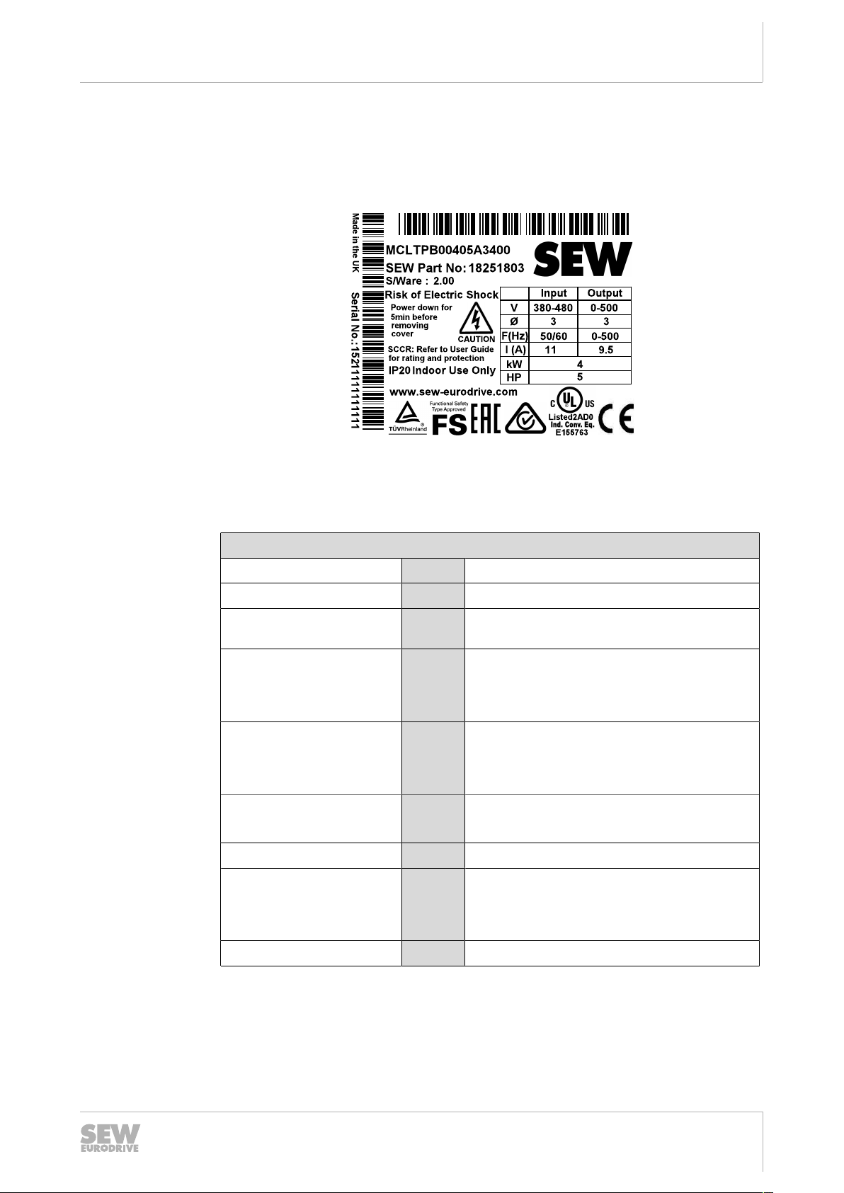
3 Device structure
3.1 Nameplate
The following figure shows an example of a nameplate.
Device structure
Nameplate
18014412064772491
3
3.2 Type designation
Product name
Version
Recommended motor
power
Connection voltage
Interference suppression
on the input
Connection type
Quadrants
Design
Example: MCLTP-B 0015-2B1-4-00 (60 Hz)
MCLTP
0015
00
MOVITRAC® LTP-B
Version status of the device series
B
0015 = 1.5kW
2 = 200 – 240V
2
5 = 380 – 480V
6 = 500 – 600V
0 = Class 0
B
A = Class C2
B = Class C1
1 = 1-phase
1
3 = 3-phase
4 = 4-quadrant operation
4
00 = Standard IP20 housing
10 = IP66/NEMA-4X housing
10 = IP55/NEMA-12K housing
22872051/EN – 09/2016
Country-specific variant
(60 Hz)
60Hz design
Operating Instructions – MOVITRAC® LTP-B
15
Device structure
+
L1/L-DC L2/N L3
BR U V W
MOVITRAC
®
LTP-B
[1]
[2]
[3]
[4]
[5]
[7]
[8]
[6]
3
Device structure of the standard inverter
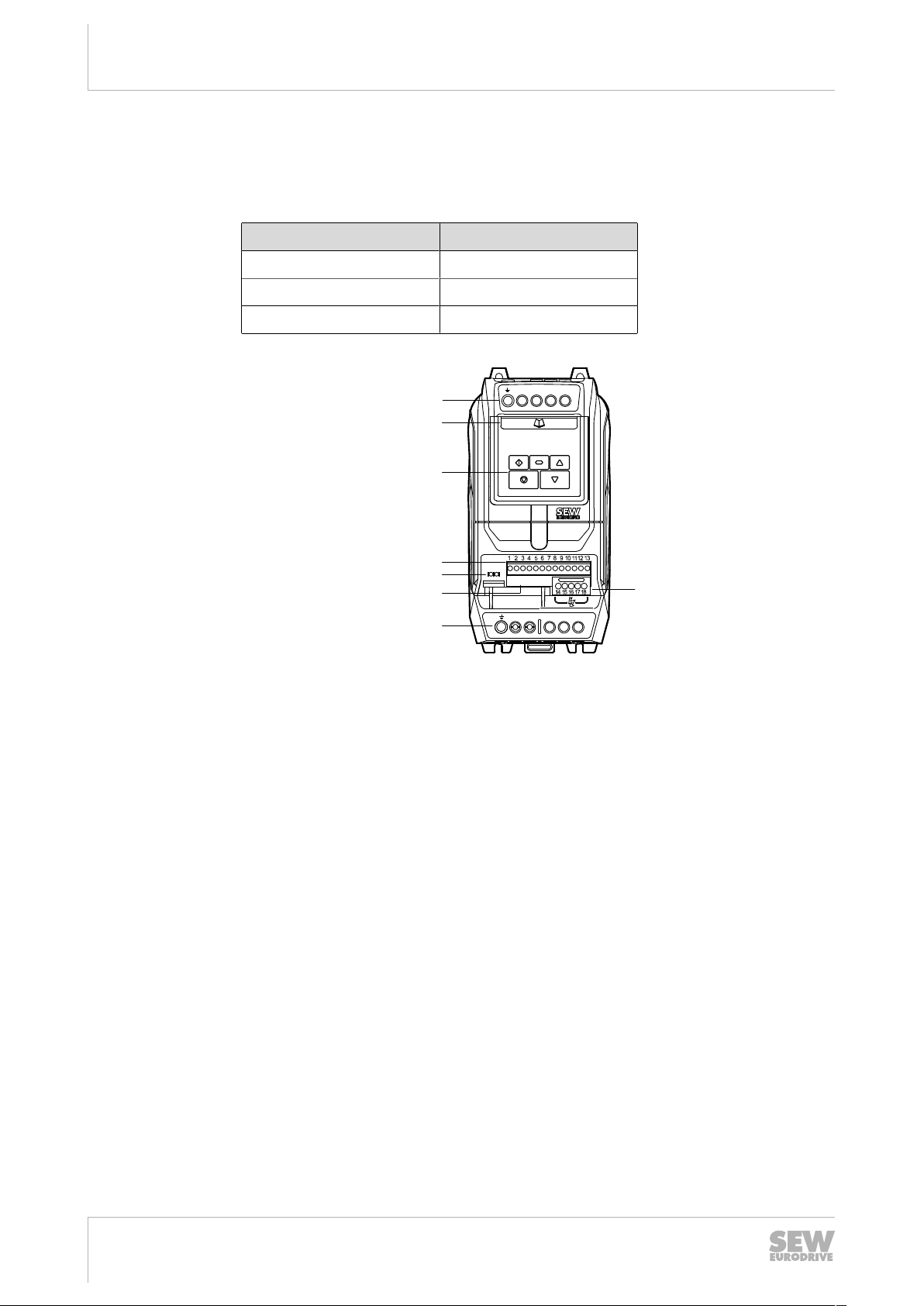
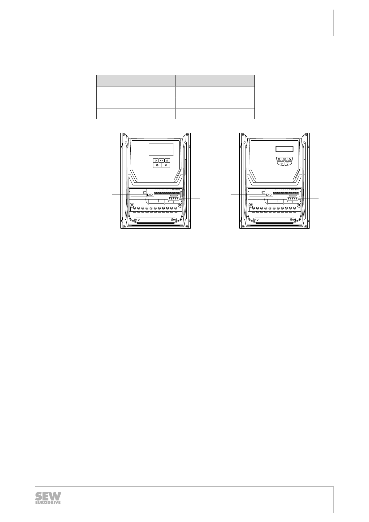
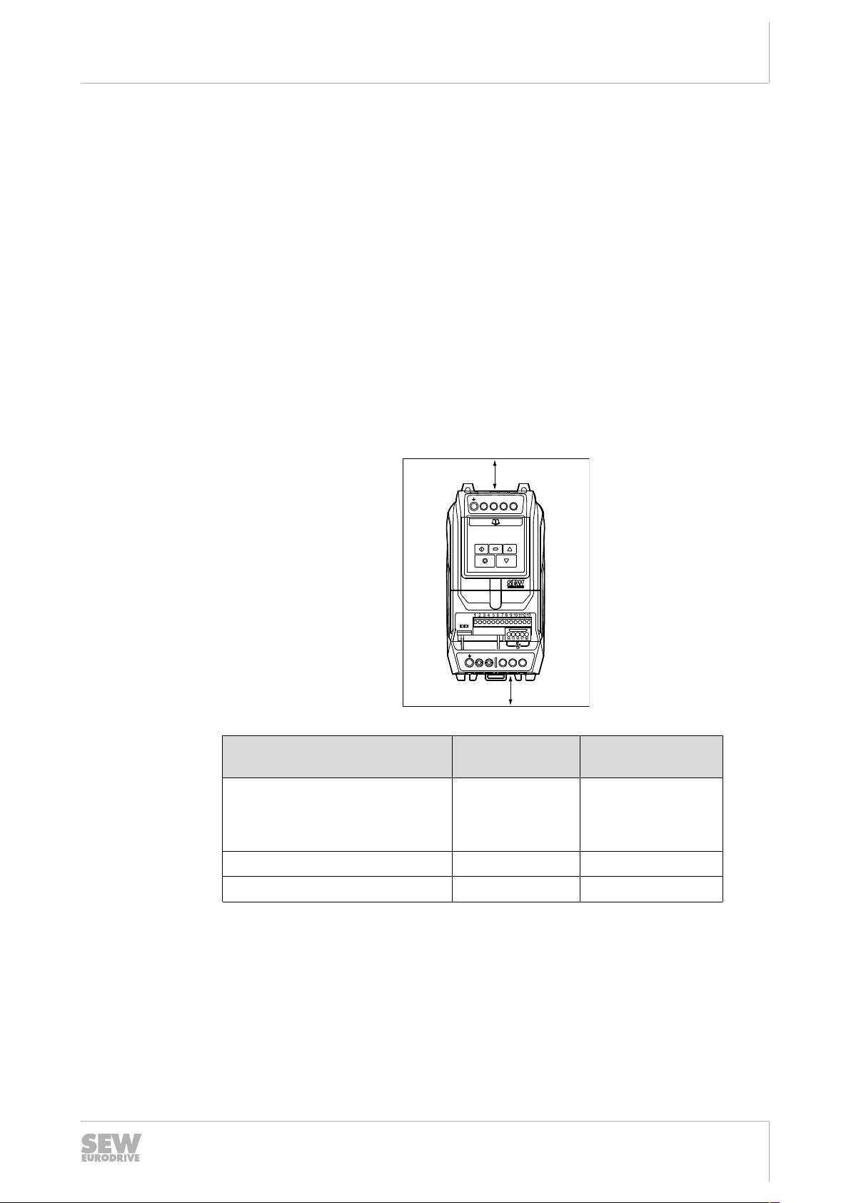
3.3 Device structure of the standard inverter
3.3.1 Inverters with degree of protection IP20/NEMA 1
The following inverters have the housing shown below:
Nominal line voltage Power of the inverter
230V
400 V
575V
0.75 – 5.5kW
0.75 – 11kW
0.75 – 15kW
[1] Connecting terminal strip PE, -DC, L1/L, L2/N, L3
17957766667
[2] Auxiliary card with terminal assignment and basic parameters
[3] Keypad with a 6-digit 7-segment display
[4] Control terminal strip (pluggable)
[5] RJ45 communication socket
[6] Option card slot
[7] Connecting terminal strip PE, +, BR, U, V, W
[8] Relay terminal strip (pluggable)
22872051/EN – 09/2016
16
Operating Instructions – MOVITRAC® LTP-B
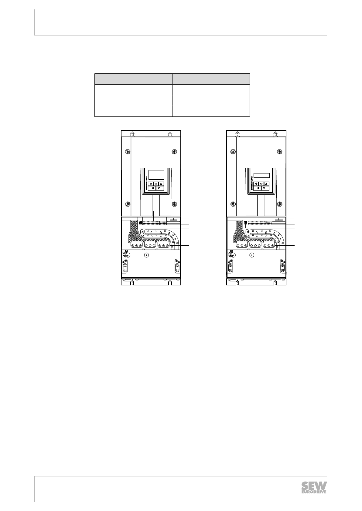
3.3.2 Inverters with degree of protection IP66/NEMA 4X
[1]
[2]
[3]
[4]
[5]
[6]
[1]
[2]
[3]
[4]
[5]
[6]
[7] [7]
The following inverters have the housing shown below:
Nominal line voltage Power of the inverter
Device structure
Device structure of the standard inverter
3
230V
400 V
575V
[1] Full text display/6-digit 7-segment display
[2] Keypad
[3] Control terminal strip (pluggable)
0.75 – 4kW
0.75 – 7.5kW
0.75 – 11kW
17957961099
22872051/EN – 09/2016
[4] Relay terminal strip (pluggable)
[5] Connecting terminal strip PE, L1/L, L2/N, L3, -DC, +, BR, U, V, W
[6] RJ45 communication socket
[7] Option card slot
Operating Instructions – MOVITRAC® LTP-B
17
Device structure
L1 +DC U V WBR -DCL2 L3
[1]
[2]
[3]
[5]
[6]
[7]
L1 +DC U V WBR -DCL2 L3
[1]
[2]
[3]
[5]
[6]
[7]
[4] [4]
3
Device structure of the standard inverter
3.3.3 Inverters with degree of protection IP55/NEMA 12K
The following inverters have the housing shown below:
Nominal line voltage Power of the inverter
230V
400 V
575V
5.5 – 75kW
11 – 160kW
15 – 110kW
[1] Full text display/6-digit 7-segment display
[2] Keypad
[3] Control terminal strip (pluggable)
[4] Option card slot
[5] Relay terminal strip (pluggable)
[6] RJ45 communication socket
[7] Connecting terminal strip PE, L1/L, L2/N, L3, -DC, +, BR, U, V, W
17957963531
22872051/EN – 09/2016
18
Operating Instructions – MOVITRAC® LTP-B
4 Installation
+
L1/L-DC L2/N L3
BR U V W
MOVITRAC® LTP-B
+
L1/L-DC L2/N L3
BR U V W
MOVITRAC
®
LTP-B
+
L1/L-DC L2/N L3
BR U V W
MOVITRAC
®
LTP-B
4.1 General information
• Carefully check the inverter for damage before the installation.
• Store the inverter in its original packaging until it is used. The storage location
must be clean and dry with an ambient temperature between ‑40°C and +60°C.
• Install the inverter in a suitable housing on a level, vertical, non-flammable, and vibration-free surface. If a certain IP degree of protection is required, observe
EN60529.
• Keep flammable materials away from the inverter.
• Prevent the ingress of conductive or flammable foreign objects.
• The relative humidity must be kept below 95% (condensation is not permitted).
• Protect the IP55/IP66 inverter from direct sunlight. Use a cover when using the inverter outdoors.
• Inverters can be installed next to each other. Ensure sufficient ventilation space
between the individual devices. If the inverter is to be installed above another inverter or another device that dissipates heat, then there must be a vertical minimum clearance of 150mm. To enable self-cooling, the control cabinet must either
be cooled through forced ventilation, or dimensioned accordingly. See chapter
"IP20 housing: Installation and installation space"(→221).
• The permitted ambient temperatures are defined in chapter "Ambient
conditions"(→2174).
• The mounting rail installation is only possible for the following inverters with degree
of protection IP20.
– 230V: 0.75 – 2.2kW
– 400V: 0.75 – 4kW
– 575V: 0.75 – 5.5kW
The mounting rail must have the dimensions 35 × 15mm or 35 × 7.5mm and be
designed according to EN50022.
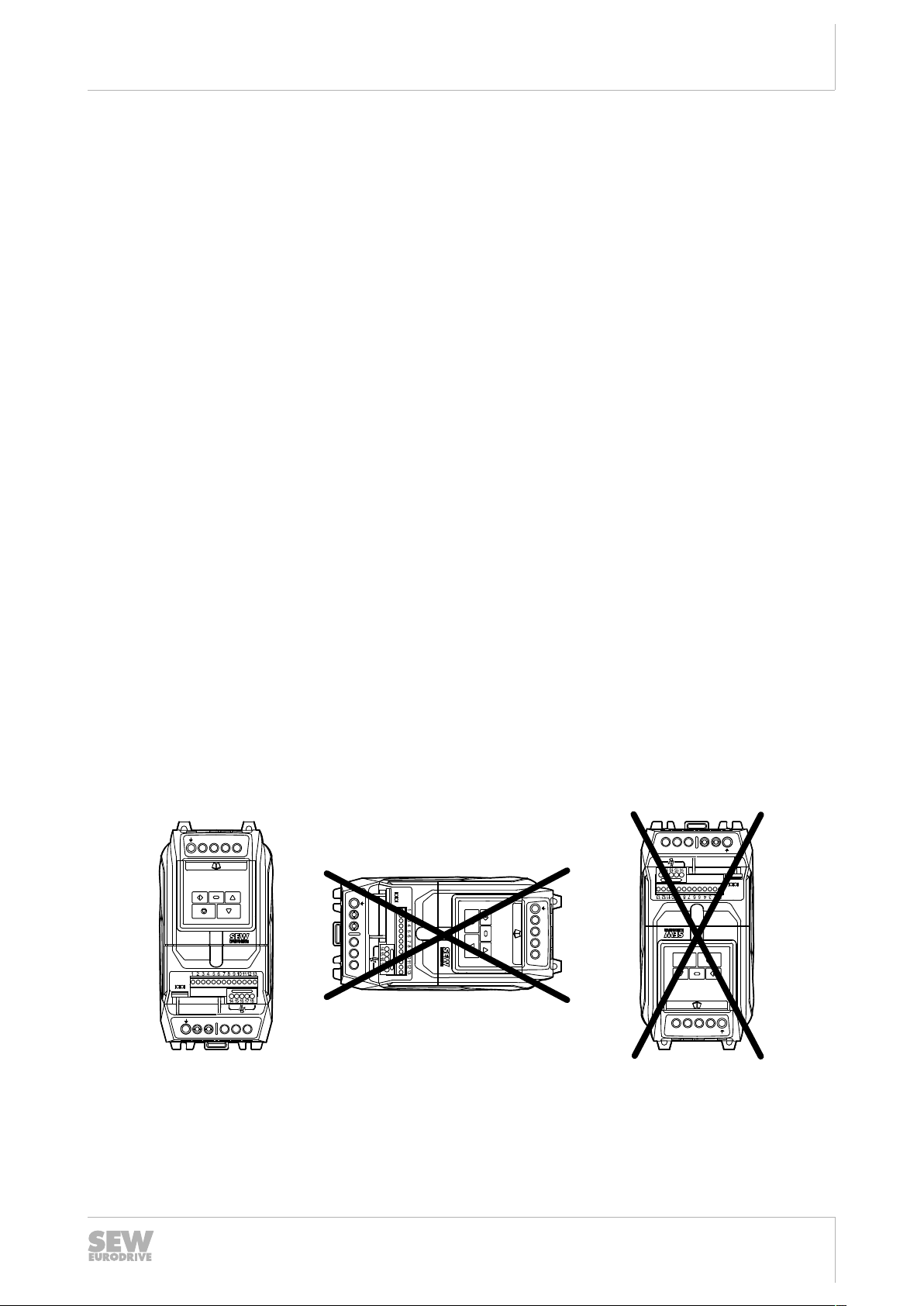
• Install the frequency inverter only as depicted in the following figure:
Installation
General information
4
22872051/EN – 09/2016
7312622987
Operating Instructions – MOVITRAC® LTP-B
19
Installation
4
Permitted tightening torques
4.2 Permitted tightening torques
Tightening torque in Nm for inverter
Power of the inverter
0.75 – 2.2kW
3 – 5.5kW (IP20)
3 – 4kW (IP66)
5.5kW (IP66)
7.5 – 11kW
15 – 18.5kW
22 – 45kW
55 – 75kW
0.75 – 4kW
5.5 – 11kW (IP20)
5.5 – 7.5kW (IP66)
11kW (IP66)
15 – 22kW
30 – 37kW
Control terminals Power terminals
Nominal line voltage 230V
1
1 (IP20)
1 (IP66)
4 (IP66)
0.8
4
15
20
20
Nominal line voltage 400V
1
1 (IP20)
1 (IP66)
4 (IP66)
0.8
4
15
45 – 90kW
110 – 160kW
0.75 – 5.5kW
7.5 – 15kW (IP20)
7.5 – 11kW (IP66)
15kW (IP66)
18.5 – 30kW
37 – 45kW
55 – 110kW
Nominal line voltage 575V
0.8
20
20
1
1 (IP20)
1 (IP66)
4 (IP66)
4
15
20
20
22872051/EN – 09/2016
Operating Instructions – MOVITRAC® LTP-B
4.3 Mechanical installation
+
L1/L-DC L2/N L3
BR U V W
MOVITRAC
®
LTP-B
A
A
4.3.1 IP20 housing: Installation and installation space
Inverters with degree of protection IP20 must be installed in a control cabinet. Observe
the following requirements:
• The control cabinet must be made of a heat conductive material unless it has
forced cooling.
• When using a control cabinet with ventilation openings, the openings must be
provided above and underneath the inverter to allow for unobstructed circulation of
air. The air must be supplied underneath the inverter and dissipated above it.
• If the inverter is operated in environments with particles of dirt (such as dust), ventilation openings either have to be equipped with a suitable particle filter or forced
cooling has to be used. The filter has to be serviced and cleaned.
• In environments with a high level of humidity, salt or chemicals, a suitable enclosed control cabinet (without ventilation openings) must be used.
• The inverters with degree of protection IP20 can be installed right next to each
other without clearance.
Installation
Mechanical installation
4
22872051/EN – 09/2016
17958518795
Power of the inverter A in mm Air flow rate per in-
verter
230V: 0.75 kW, 1.5 kW
60 > 45m3/h
400V: 0.75kW, 1.5kW, 2.2kW
575V: 0.75 – 5.5kW
230V: 2.2kW
All other power ranges
100 > 45m3/h
100 > 80m3/h
Operating Instructions – MOVITRAC® LTP-B
21
Installation
A
A
A
B B B
4
Mechanical installation
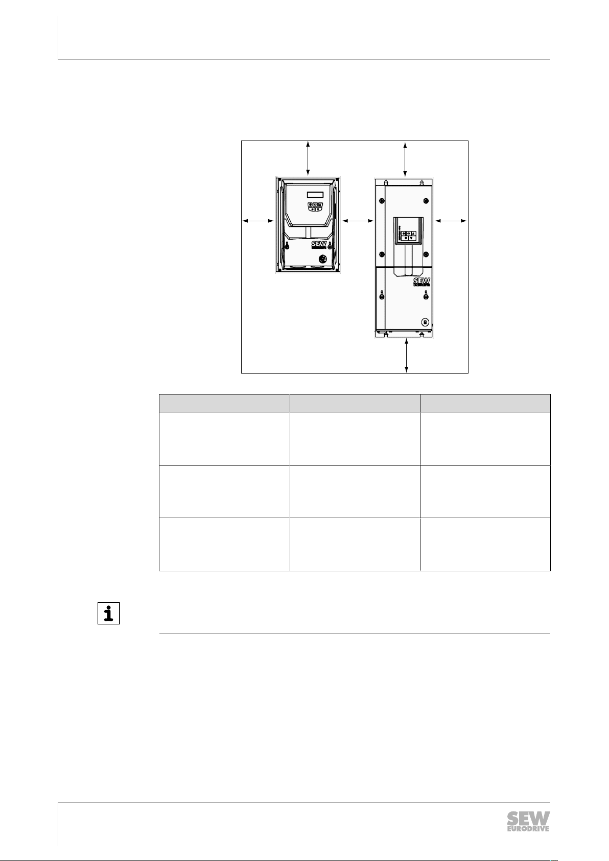
4.3.2 IP55/IP66 housing: Installation and control cabinet dimensions
Inverters with degree of protection IP55/IP66 can be used indoors.
In control cabinets or in field, the following minimum distances must not be underrun.
9007208910888971
Power of the inverter A in mm B in mm
230V
0.75 – 4kW
5.5 – 75kW
400 V
0.75 – 7.5kW
11 – 160kW
575V
0.75 – 11kW
15 – 110kW
100
200
100
200
100
200
10
10
10
10
10
10
INFORMATION
If the IP55/IP66 inverter is installed in a control cabinet, a sufficient control cabinet
ventilation must be ensured.
22
Operating Instructions – MOVITRAC® LTP-B
22872051/EN – 09/2016
4.4 Electrical installation
WARNING
Electric shock due to charged capacitors. Dangerous voltage levels may still be
present inside the device and at the terminals up to 10minutes after disconnection
from the power supply.
Severe or fatal injuries.
• Wait 10minutes after you have de-energized the inverter and have switched off
the line voltage and the DC24V voltage. Do not start working on the device until
you have made sure that it is de-energized.
WARNING
Danger of fatal injury due to falling hoist.
Severe or fatal injuries.
• The inverter is not designed for use as a safety device in lifting applications. Use
monitoring systems or mechanical protection devices to ensure safety.
Installation
Electrical installation
4
4.4.1 Before installation
22872051/EN – 09/2016
• The inverters may only be installed by electrical specialists in compliance with the
applicable directives and regulations.
• The grounding cable must be designed for the maximum fault current of the
voltage source that is usually limited by fuses or motor protection switches.
• The inverter has the degree of protection IP20. For a higher IP degree of protection, a suitable enclosure or the IP55/NEMA 12K or the IP66/NEMA 4X variant has
to be used.
• Make sure the devices are properly grounded. Adhere to the wiring diagram in
chapter "Connecting the inverter and motor"(→249).
• Make sure that supply voltage, frequency, and number of phases (single- or threephase) correspond with the nominal values of the inverter on delivery.
• A disconnecting switch or similar disconnecting element must be installed between
voltage supply and inverter.
• Never connect the power supply to the output terminals U, V or W of the inverter.
• Do not install contactors between inverter and motor. Adhere to a minimum clearance of 100 mm at points where control cables and electric power lines are installed close to each other, and an angle of 90°for crossing cables.
• The cables are only protected by slow-blow high-power fuses or motor circuit
breaker. You find more information in section "Permitted voltage supply
systems"(→227).
• It is recommended that you use a 4-core PVC-insulated and shielded cable as the
power cable. Route this cable according to the applicable national regulations of
the industry sector as well as the rules and standards. Conductor end sleeves are
required for connecting the power cables to the inverter.
• Make sure that shieldings and sheaths of power cables are designed according to
the wiring diagram in section "Connecting inverter and motor"(→249).
• The grounding terminal of each inverter must be connected individually and dir-
ectly to the ground busbar (mass) of the installation site (via filter, if available).
Operating Instructions – MOVITRAC® LTP-B
23
Installation
$ 30 s
t
U
N
4
Electrical installation
• Do not loop the ground connections of the inverter from one inverter to the other.
Neither route the ground connections to the inverters from other inverters.
• The impedance of the ground circuit must comply with the local safety regulations
of the industry sector.
• Make sure that all terminals are tightened with the respective tightening torques,
see chapter "Technical data"(→2173).
• To comply with UL regulations, all earth connections must be designed with UL listed crimping cable lugs.
Unlike direct operation in the supply system, inverters on the motor generate suitable
fast-switching output voltages (PWM). In the case of motors wound for operation with
adjustable-speed drives, no further preventive actions are necessary. If, however, the
insulation quality is unknown, contact the manufacturer of the motor because preventive actions may be necessary.
INFORMATION
Make sure that the earth connections are properly connected. The inverter can generate leakage currents > 3.5 mA. The grounding cable must be sufficiently dimensioned to carry the maximum fault current of the voltage source that is usually limited
by fuses or miniature circuit breakers. Sufficiently rated fuses or miniature circuit
breakers must be integrated into the inverter's mains supply in accordance with local
laws and/or regulations.
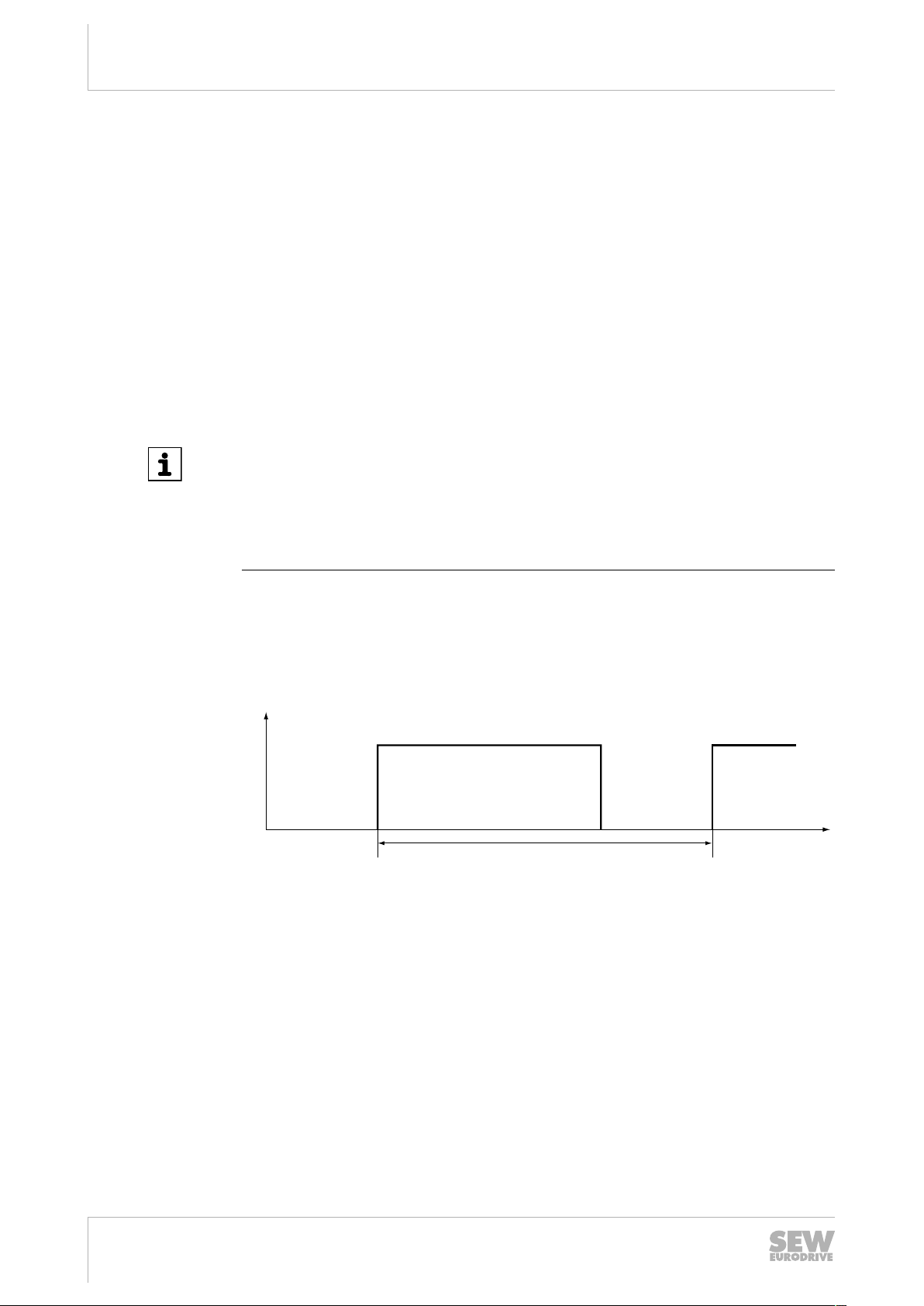
4.4.2 Line contactors
Use only line contactors in utilization category AC-3 (EN60947-4-1).
Make sure to wait at least 30seconds between 2 switching cycles.
18442995979
24
Operating Instructions – MOVITRAC® LTP-B
22872051/EN – 09/2016
4.4.3 Mains fuses
Fuse types:
• Line protection types in operation classes gL, gG:
• Power circuit breaker with characteristic B:
Residual current device
No protection against electric shock if an incorrect type of residual current device is
used.
Severe or fatal injuries.
• Use only universal current sensitive residual current devices of type B for invert-
Installation
Electrical installation
– Rated fusing voltage ≥ rated line voltage
– The nominal fusing current must be designed for at least 100% of the inverter
nominal input current depending on the inverter utilization.
– Nominal circuit breaker voltage ≥ nominal line voltage
– The nominal currents of the power circuit breakers must be 10% higher than
the nominal inverter current.
WARNING
ers.
4
• Inverters generate a DC current component in the leakage current and can significantly reduce the sensitivity of an residual current device of type A. A type A residual current device is this not permitted as protection device.
• If the use of a residual current device is not mandatory according to the standards,
SEW‑EURODRIVE recommends not to use a residual current device.
22872051/EN – 09/2016
Operating Instructions – MOVITRAC® LTP-B
25
Installation
[1]
[2]
L3
N/L2
L/L1
Internal
EMC
Filter
Internal
Surge
Protection
Earth
EMC
VAR
4
Electrical installation
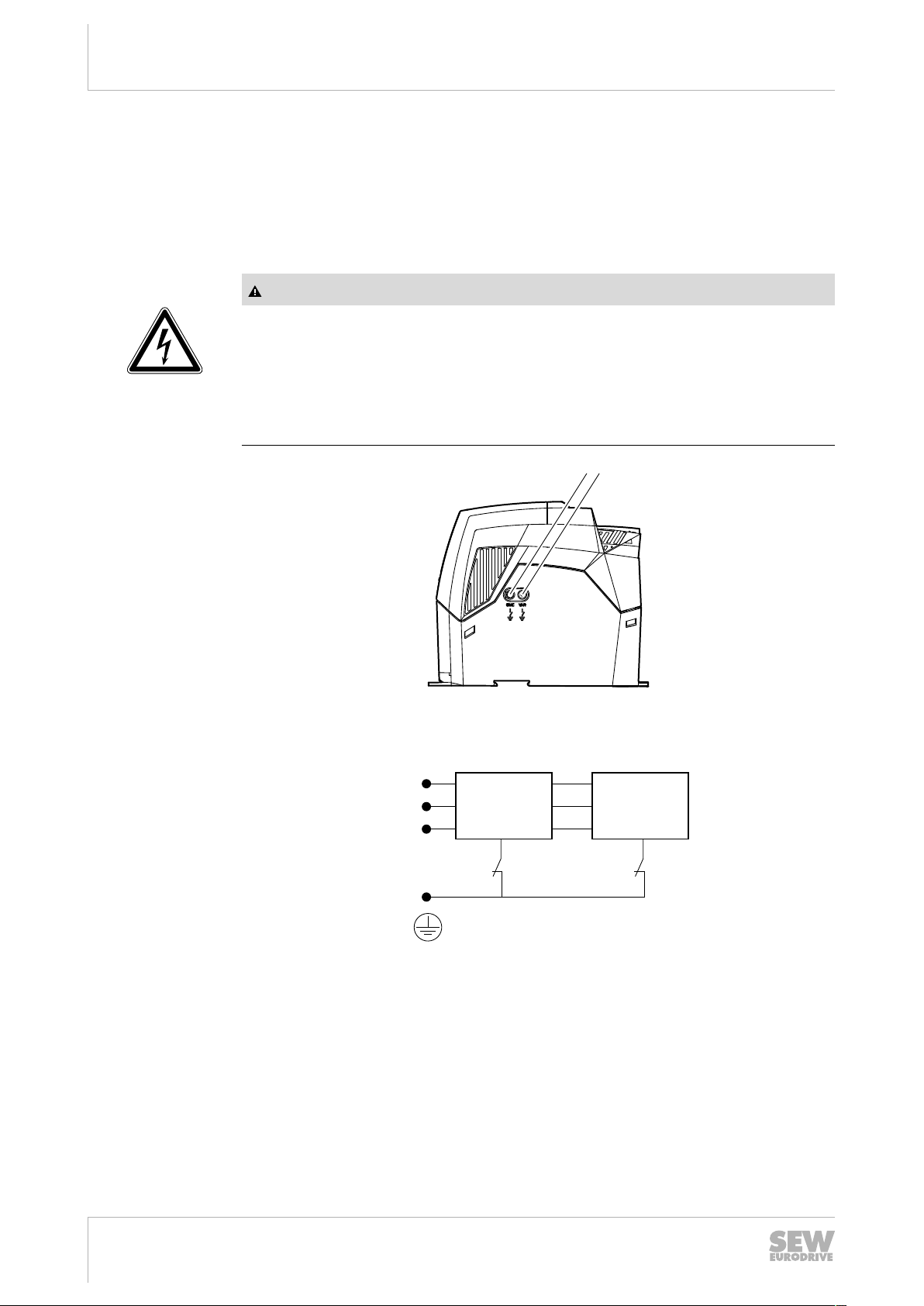
4.4.4 Operation on an IT system
IP20 devices can be operated on the IT system as described below. Please contact
SEW‑EURODRIVE for all other devices.
For operation on the IT system, the connection of the overvoltage protection and the
EMC filter to PE has to be separated. Screw out the EMC and VAR screw on the side
of the device.
Danger of electric shock. Dangerous voltage levels may still be present inside the inverter and at the terminals up to 10minutes after disconnection from the power supply.
Severe or fatal injuries.
• Disconnect the inverter from the power supply at least 10 minutes before you
WARNING
screw out the EMC and VAR screw.
3034074379
EMC screw
[1]
VAR screw
[2]
9007204745593611
SEW‑EURODRIVE recommends using earth-leakage monitors with pulse code measurement in voltage supply systems with a non-grounded star point (IT systems). Use
of such devices prevents the insulation monitor mis-tripping due to the earth capacitance of the inverter.
22872051/EN – 09/2016
26
Operating Instructions – MOVITRAC® LTP-B

4.4.5 Operation on a TN system with an RCD switch (IP20)
IP20 inverters with integrated EMC filter (such as MOVITRAC®LT xxxx xAx-x-00 or
MOVITRAC®LT xxxx xBx-x-00) have a higher leakage current than devices without
EMC filter. The EMC filter may cause errors when operated with a RCCB. Deactivate
the EMC filter to reduce the leakage current. To do so, screw out the EMC and VAR
screw on the side of the device. See figure in chapter "Operation on an IT
system"(→226).
4.4.6 Permitted voltage supply systems
• Voltage supply systems with grounded star point
Inverters with all degrees of protection are intended for operation on TN and TT
systems with directly grounded star point.
• Voltage supply systems with non-grounded star point
Operation on voltage supply systems with non-grounded star point (for example IT
systems) is only permitted for inverters with degree of protection IP20. See chapter
"Operation on an IT system"(→226).
• Voltage systems with grounded outer conductor
On voltage supply systems, the inverters with all degrees of protection may only
be operated with a maximum phase-to-ground AC voltage of 300V.
Installation
Electrical installation
4
4.4.7 Help card
The help card contains an overview of the terminal assignment and additionally an
overview of the basic parameters of parameter group1.
In the IP55/IP66 housing, the help card is attached behind the removable front cover.
In the IP20 housing, the help card is inserted in a slot above the display.
22872051/EN – 09/2016
Operating Instructions – MOVITRAC® LTP-B
27
Installation
4
Electrical installation
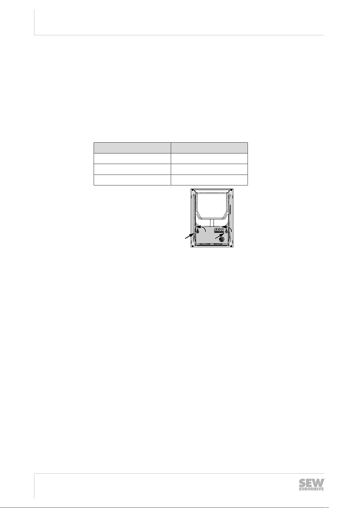
4.4.8 Removing the terminal cover
To access the terminals of inverters with degree of protection IP55/IP66, remove the
front cover of the frequency inverter. Only use cross-head or slot screwdrivers to open
the terminal cover.
The connection terminals can be accessed when the screws on the front of the
product are removed as shown below.
The front cover is attached by proceeding in reverse order.
Inverters with degree of protection IP66/NEMA 4X
The following inverters have the housing shown below:
Nominal line voltage Power of the inverter
230V
400 V
575V
0.75 – 4kW
0.75 – 7.5kW
0.75 – 11kW
18157858827
28
22872051/EN – 09/2016
Operating Instructions – MOVITRAC® LTP-B
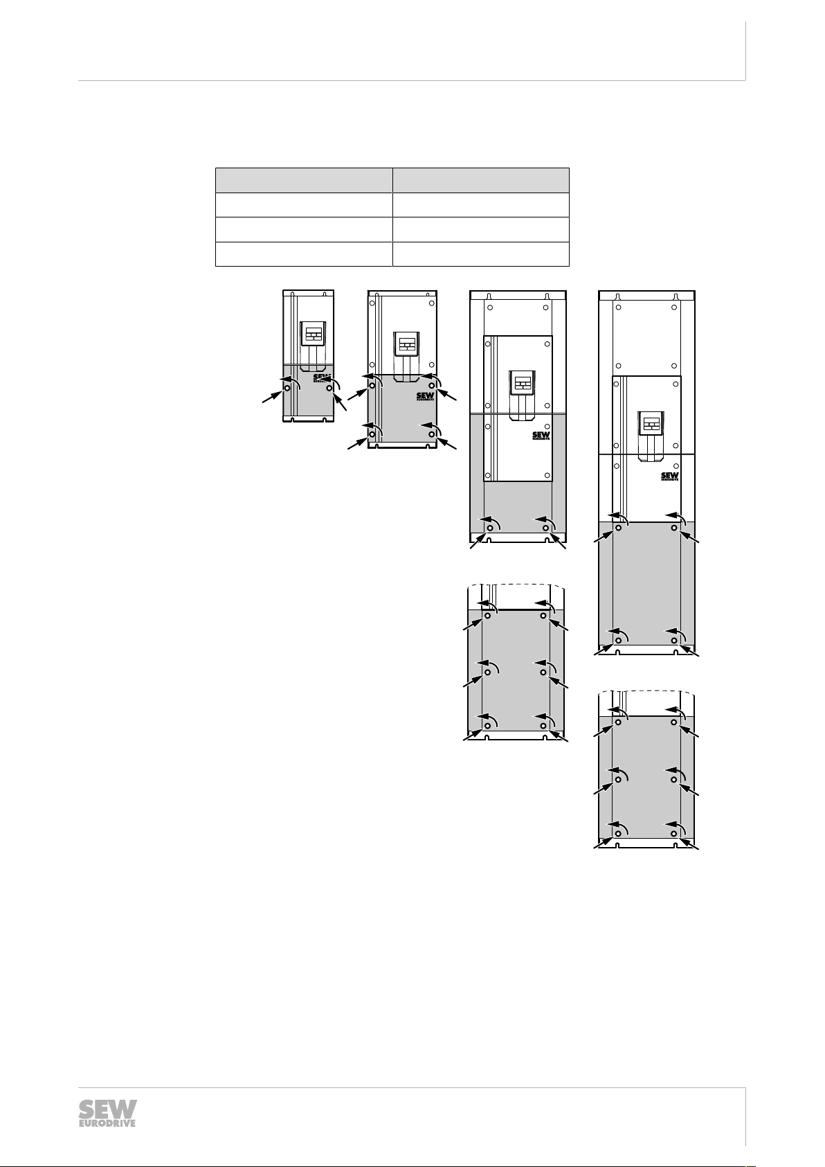
Inverters with degree of protection IP55/NEMA 12K
MOVITRAC
®
LTP B
MOVITRAC
®
LTP B
MOVITRAC
®
LTP B
MOVITRAC
®
LTP B
[1] [2] [3] [4]
The following inverters have the housing shown below:
Nominal line voltage Power of the inverter
Installation
Electrical installation
4
230V
400 V
575V
5.5 – 75kW
11 – 160kW
15 – 110kW
22872051/EN – 09/2016
9007212609488907
[1]
• 230V: 5.5 – 11kW
• 400V: 11 – 22kW
• 575V: 15 – 30kW
[2]
• 230V: 15 – 18.5kW
• 400V: 30 – 37kW
[3]
• 230V: 22 – 45kW
• 400V: 45 – 90kW
• 575V: 55 – 110kW
[4]
• 230V: 55 – 75kW
• 400V: 110 – 160kW
• 575V: 37 – 45kW
Operating Instructions – MOVITRAC® LTP-B
29
Installation
4
Electrical installation
4.4.9 Cable gland plate
A suitable cable gland system is required to maintain the respective IP/NEMA degree
of protection. Cable entry holes have to be drilled that correspond to this system.
NOTICE
Drilling cable entry holes may lead to particles entering the inverter.
Possible damage to property.
• Be careful when drilling the hole to prevent particles from entering the inverter.
→ Remove all particles at and in the inverter.
Some guide sizes are listed below:
Recommended hole sizes and hole types for the cable gland.
Power of the inverter Hole size Imperial Metrical
230V: 0.75 – 4kW
400V: 0.75 – 7.5kW
575V: 0.75 – 11kW
Hole sizes for flexible electrical installation ducts
Power of the inverter Hole size Commercial size Metrical
230V: 0.75 – 4kW
400V: 0.75 – 7.5kW
575V: 0.75 – 11kW
An IP degree of protection is only ensured when the cables are installed with a bushing or sleeve for a flexible electrical installation duct approved by UL.
When installing electrical installation ducts, the insertion holes of the duct must have
standard openings for the required sizes according to NEC specifications.
Not intended for rigid electrical installation ducts.
25mm PG16 M25
35mm 1in M25
30
22872051/EN – 09/2016
Operating Instructions – MOVITRAC® LTP-B
 Loading...