

SEW MOVITRAC LTE-B series Operating Instructions Manual
Drive Technology \ Drive Automation \ System Integration \ Services
Operating Instructions
MOVITRAC
Edition 11/2012 20045344 / EN
®
LTE-B
SEW-EURODRIVE—Driving the world

Contents
Contents
1 General information ............................................................................................ 5
1.1 How to use this documentation................................................................... 5
1.2 Structure of the safety notes ....................................................................... 5
1.3 Rights to claim under warranty ................................................................... 6
1.4 Exclusion of liability..................................................................................... 6
1.5 Copyright..................................................................................................... 6
1.6 Product names and trademarks.................................................................. 6
2 Safety Notes ........................................................................................................ 7
2.1 Preliminary information ............................................................................... 7
2.2 General information .................................................................................... 7
2.3 Target group ............................................................................................... 7
2.4 Designated use ........................................................................................... 8
2.5 Transport..................................................................................................... 8
2.6 Installation and assembly............................................................................ 9
2.7 Electrical connection ................................................................................... 9
2.8 Safe disconnection...................................................................................... 9
2.9 Startup/operation ...................................................................................... 10
2.10 Inspection and maintenance ..................................................................... 10
3 General Specifications ..................................................................................... 11
3.1 Input voltage ranges ................................................................................. 11
3.2 Type designation....................................................................................... 12
3.3 Overload capacity ..................................................................................... 13
3.4 Protection functions .................................................................................. 13
4 Installation ......................................................................................................... 14
4.1 General information .................................................................................. 14
4.2 Mechanical installation.............................................................................. 14
4.3 Electrical installation ................................................................................. 21
5 Startup................................................................................................................ 32
5.1 User interface............................................................................................ 32
5.2 Easy startup .............................................................................................. 33
5.3 Startup for operation via fieldbus .............................................................. 34
5.4 Startup with 87 Hz characteristic curve..................................................... 37
6 Operation ........................................................................................................... 38
6.1 Status of the inverter................................................................................. 38
7 Service and Error Codes .................................................................................. 39
7.1 Troubleshooting ........................................................................................ 39
7.2 Error memory ............................................................................................ 39
7.3 Error codes ............................................................................................... 40
7.4 SEW Electronics Service .......................................................................... 42
Operating Instructions – MOVITRAC® LTE-B
3

Contents
8 Parameters......................................................................................................... 43
8.1 Standard parameters ................................................................................ 43
8.2 Advanced parameters............................................................................... 44
8.3 P-15 Binary input function selection.......................................................... 48
8.4 Parameters for monitoring operating data in real time (read only)............ 50
9 Technical Data................................................................................................... 52
9.1 Conformity................................................................................................. 52
9.2 Information on ambient conditions ............................................................ 52
9.3 Output power and current carrying capacity without filter ......................... 53
9.4 Output power and current carrying capacity with filter .............................. 58
10 Address List ...................................................................................................... 62
Index................................................................................................................... 74
4
Operating Instructions – MOVITRAC® LTE-B
1 General information
1.1 How to use this documentation
The documentation is an integral part of the product and contains important information
on operation and service. The documentation is written for all employees who assemble,
install, start up, and service this product.
The documentation must be accessible and legible. Make sure that persons responsible
for the system and its operation, as well as persons who work independently on the unit,
have read through the documentation carefully and understood it. If you are unclear
about any of the information in this documentation, or if you require further information,
contact SEW-EURODRIVE.
1.2 Structure of the safety notes
1.2.1 Meaning of signal words
The following table shows the grading and meaning of the signal words for safety notes,
warnings regarding potential risks of damage to property, and other notes.
General information
How to use this documentation
1
Signal word Meaning Consequences if disregarded
DANGER Imminent danger Severe or fatal injuries
WARNING Possible dangerous situation Severe or fatal injuries
CAUTION Possible dangerous situation Minor injuries
NOTICE Possible damage to property Damage to the drive system or its envi-
INFORMATION Useful information or tip: Simpli-
fies the handling of the drive
system.
1.2.2 Structure of the section safety notes
Section safety notes do not apply to a specific action but to several actions pertaining to
one subject. The symbols used either indicate a general hazard or a specific hazard.
This is the formal structure of a section safety note:
SIGNAL WORD
Type and source of danger.
Possible consequence(s) if disregarded.
• Measure(s) to prevent the danger.
ronment
1.2.3 Structure of the embedded safety notes
Embedded safety notes are directly integrated in the instructions just before the description of the dangerous action.
This is the formal structure of an embedded safety note:
• SIGNAL WORD Type and source of danger.
Possible consequence(s) if disregarded.
– Measure(s) to prevent the danger.
Operating Instructions – MOVITRAC® LTE-B
5

1
General information
Rights to claim under warranty
1.3 Rights to claim under warranty
A requirement of fault-free operation and fulfillment of any rights to claim under limited
warranty is that you adhere to the information in the documentation. Therefore read the
documentation before you start working with the unit.
1.4 Exclusion of liability
You must comply with the information contained in this documentation to ensure safe
operation and to achieve the specified product characteristics and performance features. SEW-EURODRIVE assumes no liability for injury to persons or damage to equipment or property resulting from non-observance of these operating instructions. In such
cases, any liability for defects is excluded.
1.5 Copyright
© 2012 – SEW-EURODRIVE. All rights reserved.
Unauthorized duplication, modification, distribution or any other use of the whole or any
part of this documentation is strictly prohibited.
1.6 Product names and trademarks
All product names in this documentation are trademarks or registered trademarks of
their respective titleholders.
6
Operating Instructions – MOVITRAC® LTE-B
2 Safety Notes
2.1 Preliminary information
The following basic safety notes must be read carefully to prevent injury to persons and
damage to property. The operator must ensure that the basic safety notes are read and
adhered to. Make sure that persons responsible for the system and its operation, as well
as persons who work independently on the unit, have read through the operating instructions carefully and understood them. If you are unclear about any of the information in
this documentation, or if you require further information, please contact SEWEURODRIVE.
The following safety notes are primarily concerned with the use of MOVIPRO
you use other SEW components, also refer to the safety notes for the respective components in the corresponding documentation.
Please also observe the supplementary safety notes in the individual chapters of this
documentation.
Safety Notes
Preliminary information
®
units. If
2
2.2 General information
WARNING
Depending on its enclosure, the unit may have live, uninsulated as well as moving or
rotating parts and hot surfaces during operation.
Severe or fatal injuries.
• All work related to transport, putting into storage, setting up/mounting, connection,
startup, maintenance and repair may only be performed by trained personnel
observing
– The relevant detailed documentation
– The warning and safety signs on the unit
– All other relevant project planning documents, operating instructions and wiring
diagrams
– The specific regulations and requirements for the system, and
– The national/regional regulations governing safety and the prevention of acci-
dents
• Never install damaged products.
• Submit a complaint to the shipping company immediately in the event of damage.
Removing covers without authorization, improper use or incorrect installation and
operation may result in severe injuries to persons or damage to machinery.
Refer to the following chapters for more information.
2.3 Target group
Any mechanical work may only be performed by adequately qualified personnel. Qualified personnel in the context of this documentation are persons familiar with the design,
mechanical installation, troubleshooting and servicing of the product who possess the
following qualifications:
• Training in mechanical engineering, e.g. as a mechanic or mechatronics technician
(final examinations must have been passed).
• They are familiar with this documentation.
Operating Instructions – MOVITRAC® LTE-B
7

2
Safety Notes
Designated use
Any electronic work may only be performed by adequately qualified electricians. Qualified electricians in the context of this documentation are persons familiar with electrical
installation, startup, troubleshooting and servicing of the product who possess the
following qualifications:
• Training in electrical engineering, e.g. as an electrician or mechatronics technician
(final examinations must have been passed).
• They are familiar with this documentation.
In addition to that, they must be familiar with the relevant safety regulations and laws,
especially with the requirements of the performance levels according to
DIN EN ISO 13849-1 and all other standards, directives and laws specified in this
documentation. The above mentioned persons must have the authorization expressly
issued by the company to operate, program, configure, label and ground units, systems
and circuits in accordance with the standards of safety technology.
All work in further areas of transportation, storage, operation and waste disposal must
only be carried out by persons who are trained appropriately.
2.4 Designated use
Frequency inverters are components for controlling asynchronous AC motors. Frequency inverters are intended for installation in electrical systems or machines. Never
connect capacitive loads. Operation with capacitive loads results in over voltages and
may destroy the unit.
The following standards apply, if the frequency inverters are marketed in the EU/EFTA:
• In case of installation in machines, startup of the drive inverters (meaning the start of
proper use) is prohibited until it is determined that the machine meets the requirements stipulated in Directive 2006/42/EC (machine directive); observe EN 60204.
• Startup (i.e. the start of designated use) is only permitted under observance of the
EMC (2004/108/EC) directive.
• The frequency inverters comply with the requirements of the Low Voltage Directive
2006/95/EC. The harmonized standards of the EN 61800-5-1/DIN VDE T105 series
in connection with EN 60439-1/VDE 0660 part 500 and EN 60146/VDE 0558 are applied to these frequency inverters.
Observe the technical data and the connection requirements specified on the nameplate
and the operating instructions.
2.5 Transport
Inspect the shipment for any damage that may have occurred in transit as soon as you
receive the delivery. Inform the shipping company immediately. You may need to preclude startup.
Note the following points regarding transport:
• Before transportation, cover the connections with the supplied protection caps.
• Place the unit only on the cooling fins or on a side without connectors during transportation.
• Ensure that the unit is not subject to mechanical impact during transportation.
If necessary, use suitable, sufficiently rated handling equipment. Prior to startup, remove the securing devices used for transportation.
Observe the notes on climatic conditions as stated in the “Technical Data” chapter.
8
Operating Instructions – MOVITRAC® LTE-B
2.6 Installation and assembly
Ensure that the unit is installed and cooled according to the regulations in the related
documentation.
Protect the unit from excessive strain. Especially during transportation and handling, do
not allow the components to be deformed or insulation spaces altered. Prevent mechanical damage or destruction of electrical components.
Unless expressly intended for such use, the following applications are prohibited:
• Use in potentially explosive atmospheres,
• Use in areas exposed to harmful oils, acids, gases, vapors, dust, radiation, etc.,
• Use in stationary applications with mechanical vibration and impact loads exceeding
the values stipulated in EN 61800-5-1
Observe the notes in the "Mechanical Installation" section.
2.7 Electrical connection
Safety Notes
Installation and assembly
2
Observe the applicable national accident prevention regulations when working on a live
drive controller.
Perform electrical installation according to the pertinent regulations (e.g. cable crosssections, fusing, protective conductor connection). The documentation contains additional notes.
Make sure that preventive measures and protection devices comply with the applicable
regulations (e.g. EN 60204-1 or EN 61800-5-1).
Required preventive measures:
Type of power transmission Protective measure
Direct power supply • Protective grounding
2.8 Safe disconnection
The unit meets all requirements for reliable isolation of power and electronics
connections in accordance with EN 61800-5-1. All connected circuits must also
comply with the requirements for reliable isolation so as to guarantee reliable isolation.
Operating Instructions – MOVITRAC® LTE-B
9
2
2.9 Startup/operation
Safety Notes
Startup/operation
CAUTION
The surfaces of the unit and any connected components, e.g. braking resistors, can
reach high temperatures during operation.
Danger of burns.
• Let the unit and external options cool down before you start working on them.
Do not deactivate monitoring and protection devices even for a test run.
When in doubt, switch off the unit whenever changes occur in relation to normal mode
(e.g. increased temperatures, noise, oscillation). Determine the cause of the fault and
consult SEW-EURODRIVE, if necessary.
Where required, systems in which such units are installed must be equipped with additional monitoring and protection devices in accordance with the respective applicable
safety regulations, e.g. the law governing technical equipment, accident prevention
regulations, etc.
Additional protective measures may be necessary for applications with increased potential risk. You have to check the effectiveness of protection devices each time you change
the configuration.
Connections which are not being used must be covered with the supplied protection
caps during operation.
Do not touch live components or power connections immediately after disconnecting the
unit from the voltage supply because some capacitors may still be charged. Adhere to
a minimum switch-off time of 10 minutes. Observe the corresponding labels on the unit.
When the unit is switched on, dangerous voltages are present at all power connections
as well as at any connected cables and motor terminals. This also applies even when
the unit is inhibited and the motor is at standstill.
The fact that the status LED and other display elements are no longer illuminated does
not indicate that the unit has been disconnected from the supply system and no longer
carries any voltage.
Mechanical blocking or internal safety functions of the unit can cause a motor standstill.
Eliminating the cause of the problem or performing a reset may result in the drive restarting automatically. If, for safety reasons, this is not permitted for the driven machine,
disconnect the unit from the supply system before correcting the error.
2.10 Inspection and maintenance
WARNING
Danger of electric shock due to exposed, live parts in the unit.
10
Severe or fatal injuries.
• Never open the unit.
• Only SEW-EURODRIVE is authorized to carry out repairs.
Operating Instructions – MOVITRAC® LTE-B

3 General Specifications
3.1 Input voltage ranges
Depending on the model, the inverters are designed for direct connection to the following voltage sources:
®
•MOVITRAC
• 115 V ± 10%, 1-phase, 50 – 60 Hz ± 5%
•MOVITRAC
• 200 V – 240 V ± 10%, 1-phase* / 3-phase, 50 – 60 Hz ± 5%
•MOVITRAC
• 380 V – 480 V ± 10%, 3-phase, 50 – 60 Hz ± 5%
* NOTE: Single-phase MOVITRAC
phases of a three-phase power supply system of 200 – 240 V.
Products used with a three-phase voltage source are designed for a maximum phase
imbalance of 3%. In the case of voltage sources with a phase imbalance of more than
3% (as it is common on the Indian subcontinent, in some parts of South-East Asia and
China), SEW-EURODRIVE recommends to use input chokes.
LTE-B, sizes 1, 2 (input voltage 115 V):
®
LTE-B, sizes 1, 2 and 3s (200 – 240 V):
®
LTE-B, sizes 1, 2 and 3s (380 – 480 V):
General Specifications
Input voltage ranges
®
LTE-B inverters can also be connected to two
3
Operating Instructions – MOVITRAC® LTE-B
11
3
3.2 Type designation
MC LTE 1 B 0015 2 0 1 1 00 (60 Hz)
General Specifications
Type designation
60 Hz American variant only
00 = Standard IP20 housing
10 = IP55 / NEMA-12 housing without switch
Type
Quadrants
Connection
type
Interference
suppression on
the line side
Line voltage
Recommended motor
power
20 = IP55 / NEMA-12 housing with switch
30 = IP66 / NEMA-4X housing without switch
40 = IP66 / NEMA-4X housing with switch
1 = 1Q (without brake chopper)
4 = 4Q
1 = 1-phase
3 = 3-phase
0 = Class 0
A = Class A
B = Class B
1 = 115 V
2 = 200 – 240 V
5 = 380 – 480 V
0015 = 1.5 kW
Version B
Motor 1 = Only single-phase motors
Product type MC LTE
12
Operating Instructions – MOVITRAC® LTE-B

3.3 Overload capacity
All MOVITRAC® LTE-B products have the following overload capacity:
• 150% for 60 seconds
• 175% for 2 seconds
With an output frequency of < 10 Hz, the overload capacity is reduced to 150% for
7.5 seconds.
For adjusting the motor overload, see parameter P-08 in section"Standard parameters"
(page 43).
3.4 Protection functions
• Short circuit output, phase-phase, phase-ground
• Output overcurrent
• Overload protection
• Inverter delivers 150% of the nominal motor current for 60 seconds
• Overvoltage shutdown
General Specifications
Overload capacity
3
• Setting at 123% of the maximum nominal supply voltage of the inverter
• Undervoltage shutdown
• Shutdown caused by overtemperature
• Shutdown caused by undertemperature
• The inverter is shut down when activated below –10 °C
• Line phase failure
• The running inverter is shut down when one phase of the three-phase power
supply fails for longer than 15 seconds.
Operating Instructions – MOVITRAC® LTE-B
13

4
Installation
General information
4 Installation
4.1 General information
• Before installation, check the inverter carefully to make sure it is not damaged.
• Store the inverter in a box until it is used. The inverter must be stored at temperatures
between –40 °C and +60 °C and in such a way that it is clean and dry.
• Install the inverter on a level, horizontal, flameproof and vibration-proof surface in a
suitable control cabinet. If a special degree of protection (IP) is required, the control
cabinet must comply with EN 60529.
• Do not store or use flammable substances in the vicinity of the inverter.
• Make sure no conductive or flammable objects enter the inverter.
• The maximum ambient temperature during operation is 50 °C for IP20 inverters, and
40 °C for IP55 and IP66 inverters. The minimum ambient temperature during operation is -10 °C.
Note the special degrees of protection in section "Information on ambient conditions"
(page 52).
• The relative humidity must be below 95% (non-condensing).
®
•MOVITRAC
sufficient clearance for ventilation between the units.
LTE-B units can be installed directly next to one another. There is still
If you install the inverter above another inverter or device that generates heat, adhere
to a minimum clearance of 150 mm. The control cabinet must either be cooled
through forced ventilation, or has to be big enough to dissipate the heat itself, see
section "IP20 housing: Installation and control cabinet dimensions" (page 19).
• A DIN assembly kit for mounting rails is supported only for inverter sizes 1 and 2
(IP20).
4.2 Mechanical installation
4.2.1 Housing variants and dimensions
Housing variants
MOVITRAC
• IP66 / NEMA 4X
• IP55 / NEMA 12K
• IP20 housing for installation in control cabinets
IP55 / NEMA-12K and IP66 / NEMA-4X housings are protected against humidity and
dust. This is why these inverters can be operated indoors in a dusty or damp environment. The electronics of the inverters does not differ. The only difference is in the housing dimensions and the weight.
In degrees of protection IP55 and IP66, the inverters are also available with switch options, such as main switch, direction of rotation switch, and potentiometer.
®
LTE-B is available with three housing variants:
14
Operating Instructions – MOVITRAC® LTE-B
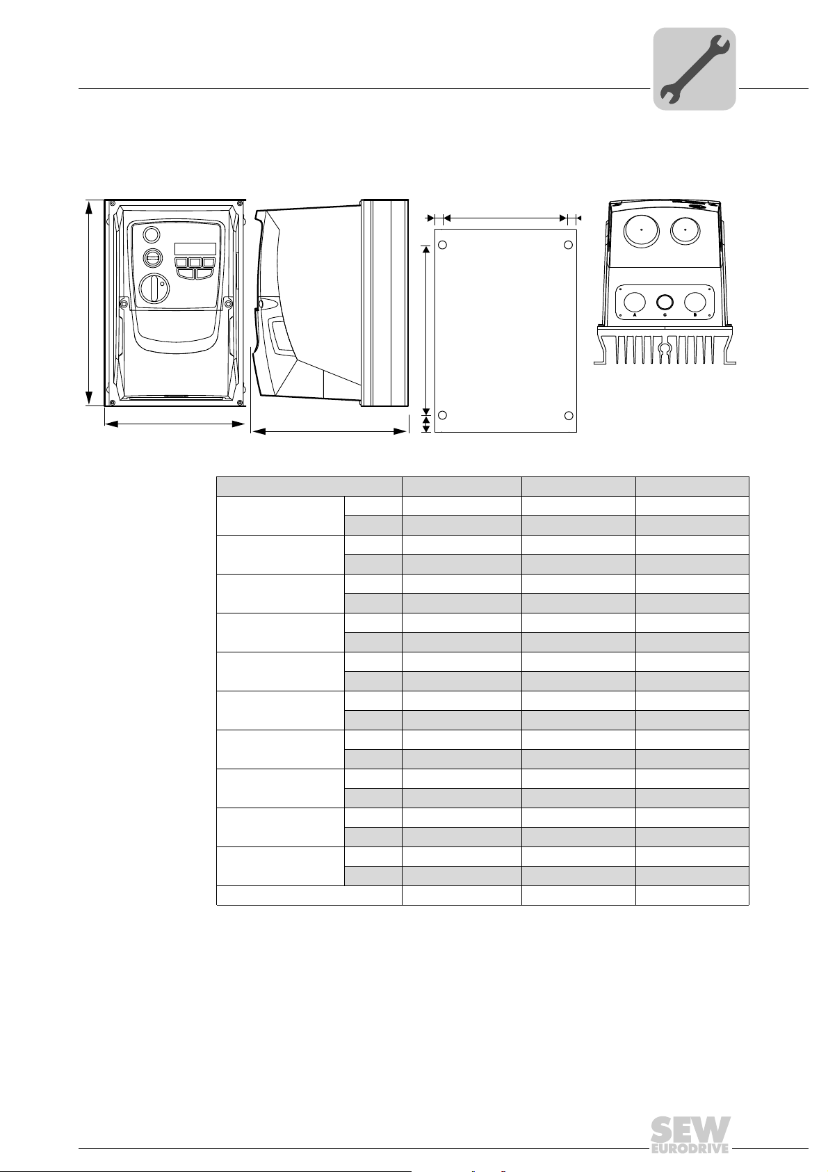
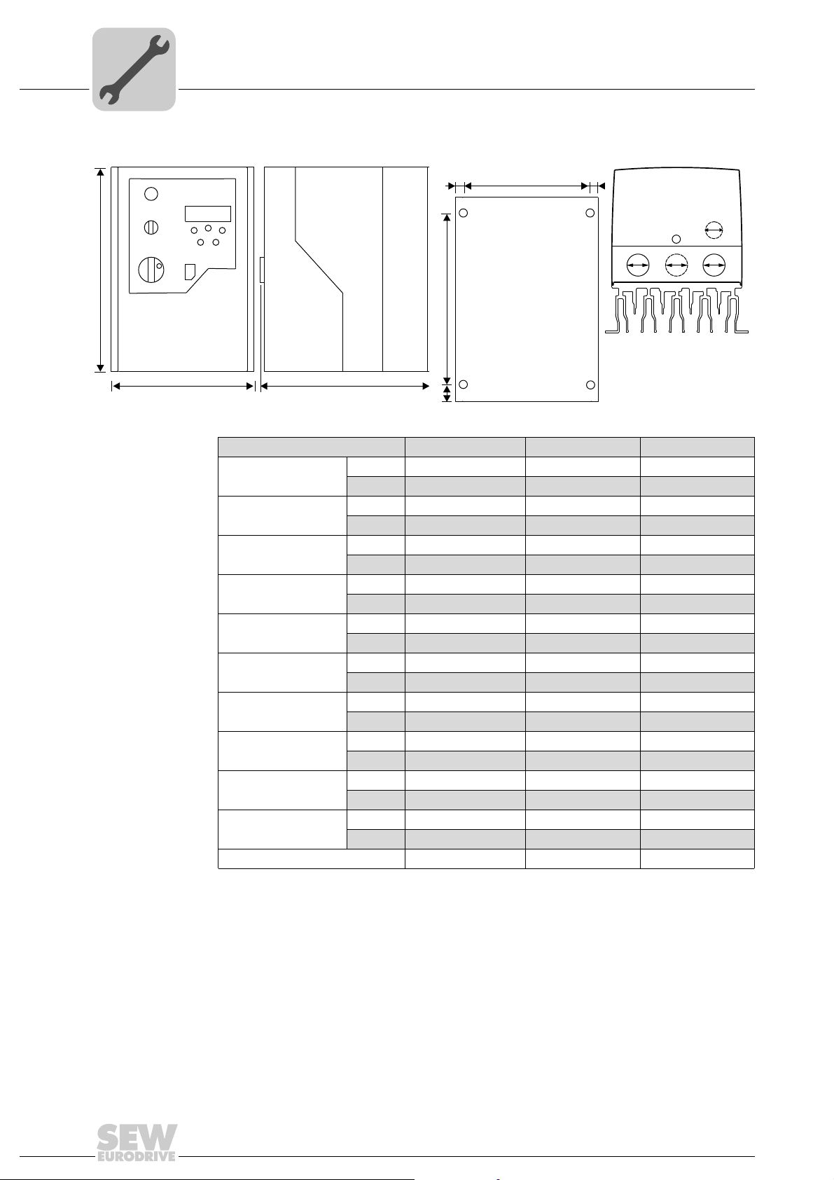
Dimensions of IP66/NEMA-4X housings (LTE xxx -30 and -40)
A
B
C
b
a
b
5923463051 5923465867 5923481739 5923484171
Installation
Mechanical installation
4
Dimensions Size 1 Size 2 Size 3
Height (A)
Width (B)
Depth (C)
Weight
a
b
c
d
Tightening torque for
power terminals
Tightening torque for
control terminals
Recommended screw size 4 × M4 4 × M4 4 × M4
mm 232 257 310
in 9.13 10.12 12.20
mm 161 188 210.5
in 6.34 7.4 8.29
mm 179 186.5 228.7
in 7.05 7.34 9
kg 2.8 4.6 7.4
lb 6.2 10.1 16.3
mm 148.5 176 197.5
in 5.85 6.93 7.78
mm 6.25 6 6.5
in 0.25 0.24 0.26
mm 25 28.5 33.4
in 0.98 1.12 1.31
mm 189 200 251.5
in 7.44 7.87 9.9
Nm 1 1 1
lb.in 8.85 8.85 8.85
Nm 0.5 0.5 0.5
lb.in 4.43 4.43 4.43
Operating Instructions – MOVITRAC® LTE-B
15
4
A
B
XX
Y
Z
Installation
Mechanical installation
Dimensions of IP55/NEMA-12 housings (LTE xxx -10 and -20)
b
d
C
6328661003 6328663819 6328679051 6328681483
Dimension Size 1 Size 2 Size 3
Height (A)
Width (B)
Depth (C)
Weight
a
b
c
d
Tightening torques of
power terminals
Tightening torques for
control terminals
Recommended screw size 2 × M4 4 × M4 4 × M4
mm 200 310 310
in 7.9 12.2 12.2
mm 140 165 211
in 5.5 6.5 8.31
mm 165 176 240
in 6.5 6.9 9.45
kg 2.3 4.5 7.4
lb 5.1 9.9 12.4
mm 128 153 196
in 5 6 7.72
mm 6 6 7
in 0.23 0.23 0.28
mm 25 25 25
in 0.98 0.98 0.98
mm 142 252 251
in 5.6 9.9 9.88
Nm 1 1 1
lb.in 8.85 8.85 8.85
Nm 0.5 0.5 0.5
lb.in 4.43 4.43 4.43
c
a
b
16
Operating Instructions – MOVITRAC® LTE-B

Dimensions of the IP20 housing
A
Installation
Mechanical installation
4
L1/L L2/N L3
d
b
1357911246810
UVW
B
C
5736914699 5736916363 5736918027
Dimensions Unit Size 1 Size 2 Size 3
Height (A)
Width (B)
Depth (C)
Weight
a
b
c
d
Tightening torques
for power terminals
Tightening torques
for control terminals
Recommended screws 4 × M4 4 × M4 4 × M4
mm 174 220 261
in 6.85 8.66 10.28
mm 79 104 126
in 3.11 4.10 4.96
mm 122.6 150 178
in 4.83 5.90 7.01
kg1.124.5
lb 2.43 4.40 10.0
mm 50 63 80
in 1.97 2.48 3.15
mm 162 209.0 247
in 6.38 8.23 9.72
mm 16 23 25.5
in 0.63 0.91 1.02
mm 5 5.25 7.25
in 0.2 0.21 0.29
Nm 1 1 1
lb.in 8.85 8.85 8.85
Nm 0.5 0.5 0.5
lb.in 4.43 4.43 4.43
d
acc
Operating Instructions – MOVITRAC® LTE-B
17

4
4.2.2 Locking IP55/66 units with switching function
Installation
Mechanical installation
The main disconnect switch can be locked in "OFF" position using a standard padlock
(20 mm). The padlock is not included in the delivery.
Press the middle of the switch to insert the padlock.
6328707979
18
Operating Instructions – MOVITRAC® LTE-B
Mechanical installation
A
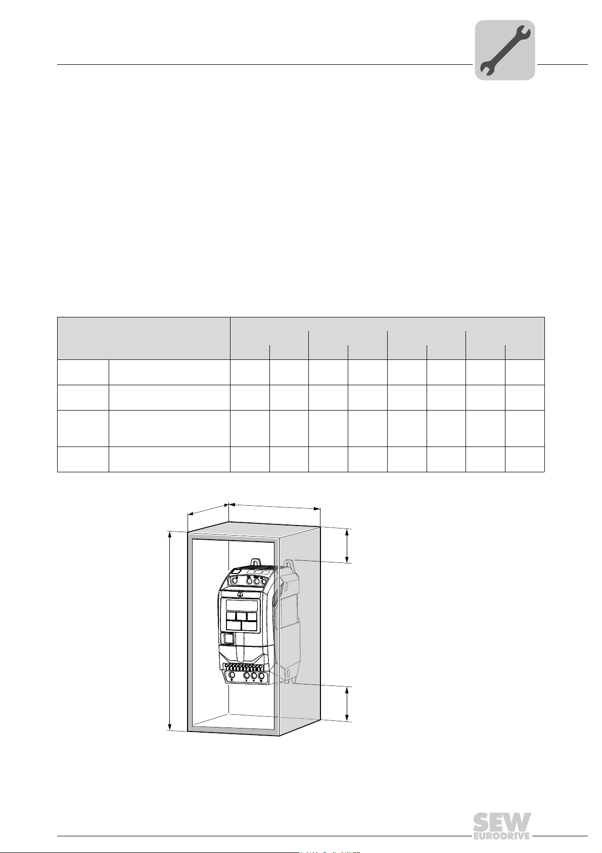
4.2.3 IP20 housing: Installation and control cabinet dimensions
For applications that require a higher IP protection level than IP20, the inverter must be
installed in a control cabinet. Observe the following requirements:
• The control cabinet must be made of a heat conductive material unless it has forced
cooling.
• When using a control cabinet with ventilation openings, the openings must be provided above and underneath the inverter to allow for unobstructed circulation of air.
The air must be supplied underneath the inverter and dissipated above it.
• If the inverter is operated in environments with particles of dirt (such as dust), ventilation openings either have to be equipped with a suitable particle filter or forced cooling has to be used. The filter has to be serviced and cleaned.
• In environments with a high level of humidity, salt or chemicals, a suitable enclosed
control cabinet (without ventilation openings) must be used.
Dimensions of control cabinets without ventilation openings
Sealed control cabinet
Power rating
Size 1
Size 1
Size 2
Size 2
115 V: 0.37 kW, 0.75 kW
230 V: 0.37 kW, 0.75 kW
230 V: 1.5 kW
400 V: 0.75 kW, 1.5 kW
115 V: 1.1 kW
230 V: 1.5 kW
400 V: 1.5 kW, 2.2 kW
230 V: 2.2 kW
400 V: 4.0 kW
A B C D
mm to mm to mm to mm to
300 11.81 250 9.84 200 7.87 50 1.97
400 15.75 300 11.81 250 9.84 75 2.95
400 15.75 300 11.81 300 11.81 60 2.36
600 23.62 450 17.72 300 11.81 100 3.94
Installation
4
C
B
D
D
5736945419
Operating Instructions – MOVITRAC® LTE-B
19
4
Installation
Mechanical installation
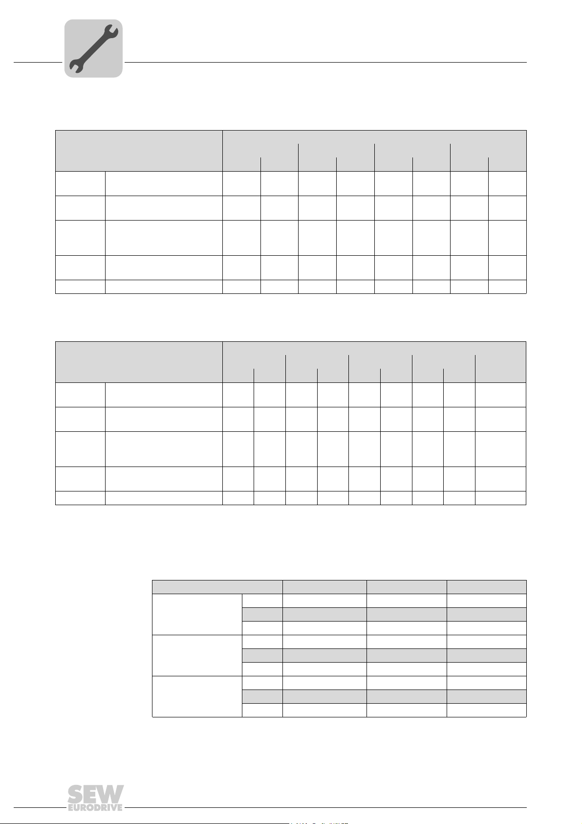
Dimensions of control cabinet with ventilation openings
Power rating
Size 1
Size 1
Size 2
Size 2
Size 3 All power ranges 800 31.50 600 23.62 300 11.81 150 5.91
115 V: 0.37 kW, 0.75 kW
230 V: 0.37 kW, 0.75 kW
230 V: 1.5 kW
400 V: 0.75 kW, 1.5 kW
115 V: 1.1 kW
230 V: 1.5 kW
400 V: 1.5 kW, 2.2 kW
230 V: 2.2 kW
400 V: 4.0 kW
Dimensions of control cabinet with forced cooling
Control cabinet with ventilation openings
A B C D
mm in mm in mm in mm in
300 11.81 250 9.84 200 7.87 50 1.97
400 15.75 300 11.81 250 9.84 75 2.95
400 15.75 300 11.81 300 11.81 60 2.36
600 23.62 450 17.72 300 11.81 100 3.94
Control cabinet with forced cooling
Power rating
Size 1
Size 1
Size 2
Size 2
Size 3 All power ranges 600 23.62 400 15.75 250 9.84 150 5.91 > 80 m
115 V: 0.37 kW, 0.75 kW
230 V: 0.37 kW, 0.75 kW
230 V: 1.5 kW
400 V: 0.75 kW, 1.5 kW
115 V: 1.1 kW
230 V: 1.5 kW
400 V: 1.5 kW, 2.2 kW
230 V: 2.2 kW
400 V: 4.0 kW
A B C D
mm in mm in mm in mm in
300 11.81 200 7.87 150 5.91 50 1.97 > 15 m
300 11.81 200 7.87 150 5.91 75 2.95 > 15 m
400 15.75 300 11.81 250 9.84 100 3.94 > 45 m
400 15.75 300 11.81 250 9.84 100 3.94 > 45 m
Air flow
4.2.4 Cable glands
Use suitable cable glands to achieve the corresponding IP/NEMA classification. The
matching holes must be drilled for this purpose. Refer to the following table for recommended dimensions.
Dimensions Size 1 Size 2 Size 3
X mm 22.3 28.2 28.2
in 0.88 1.11 1.11
PG PG13.5 / M20 PG16 / M22 PG16 / M22
1)
Y
1)
Z
1) Cable inlets Y and Z are pre-punched
mm 22 22 22
in 0.87 0.87 0.87
PG PG13.5 / M20 PG13.5 / M20 PG13.5 / M20
mm 17 17 -
in 0.67 0.67 -
PG PG9 / M16 PG9 / M16 -
rate
3
/h
3
/h
3
/h
3
/h
3
/h
20
Operating Instructions – MOVITRAC® LTE-B
4.3 Electrical installation
Adhere to the safety information in chapter 2 for installation.
WARNING
Danger of electric shock. Dangerous voltage levels can still be present inside the unit
and at the terminals up to 10 minutes after disconnection from the power supply.
Severe or fatal injuries.
• Disconnect and isolate the unit from the power supply at least 10 minutes before
starting work on MOVITRAC
•MOVITRAC
the local and national directives and regulations.
•MOVITRAC
are required, use a suitable housing or the IP55/NEMA-12 or IP66/NEMA-4X
version.
• If the inverter is supplied with power via plug and socket or coupling, then do not
remove the plug until 10 minutes after having switched off power.
• Make sure the inverters are properly grounded. See wiring diagram in section "Connecting inverter and motor" (page 25).
Installation
Electrical installation
®
LTE-B.
®
LTE inverters must be installed by qualified electricians according to
®
LTE-B has IP20 degree of protection. If higher degrees of protection
4
• The grounding cable must be designed for the maximum fault current of the voltage
source that is usually limited by fuses or motor protection switches.
Danger of fatal injury caused by falling hoist.
Severe or fatal injuries.
•MOVITRAC
4.3.1 Before installation
• Make sure that supply voltage, frequency, and number of phases (single- or threephase) dcorrespond with the nominal values of the MOVITRAC
• A disconnecting switch or similar disconnecting element must be installed between
voltage supply and inverter.
• Never connect the power supply to the output terminals U, V or W of the
MOVITRAC
• The cables are only protected by slow-blow high-power fuses or motor protection
switch. You find more information in section "Permitted voltage supply systems"
(page 23).
• Do not install automatic contactors between inverter and motor. Adhere to a minimum clearance of 100 mm at points where control cables and electric power lines
are installed close to each other, and an angle of 90° for crossing cables.
WARNING
®
LTE-B inverters may not be used as a safety device in hoist applica-
tions. Use monitoring systems or mechanical protection devices to ensure safety.
®
inverter on delivery.
®
LTE-B inverter.
Operating Instructions – MOVITRAC® LTE-B
21
4
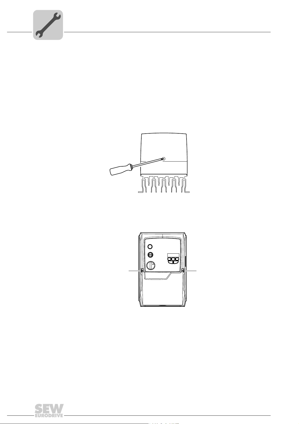
Opening the front cover
IP55 sizes 1 and 2
Installation
Electrical installation
• Make sure that shieldings and sheaths of power cables are designed according to
the wiring diagram in section "Connecting inverter and motor" (page 25).
• Make sure that all terminals have been tightened with the proper tightening torques.
• Control terminals: 0.5 Nm
• Power terminals: 1 Nm
To loosen the front cover, position the screwdriver in the opening as shown in the following figure.
IP55 size 3, and IP66 all sizes
Remove the two screws on the inverter's front to open the front cover.
[1] Screws of the front cover
Quick reference
guide
A quick reference guide is available in the IP20 housing in a separate tray above the display. In IP55/IP66 housings, the quick reference guide is attached inside the front cover.
2933381515
[1][1]
2933384203
22
Operating Instructions – MOVITRAC® LTE-B

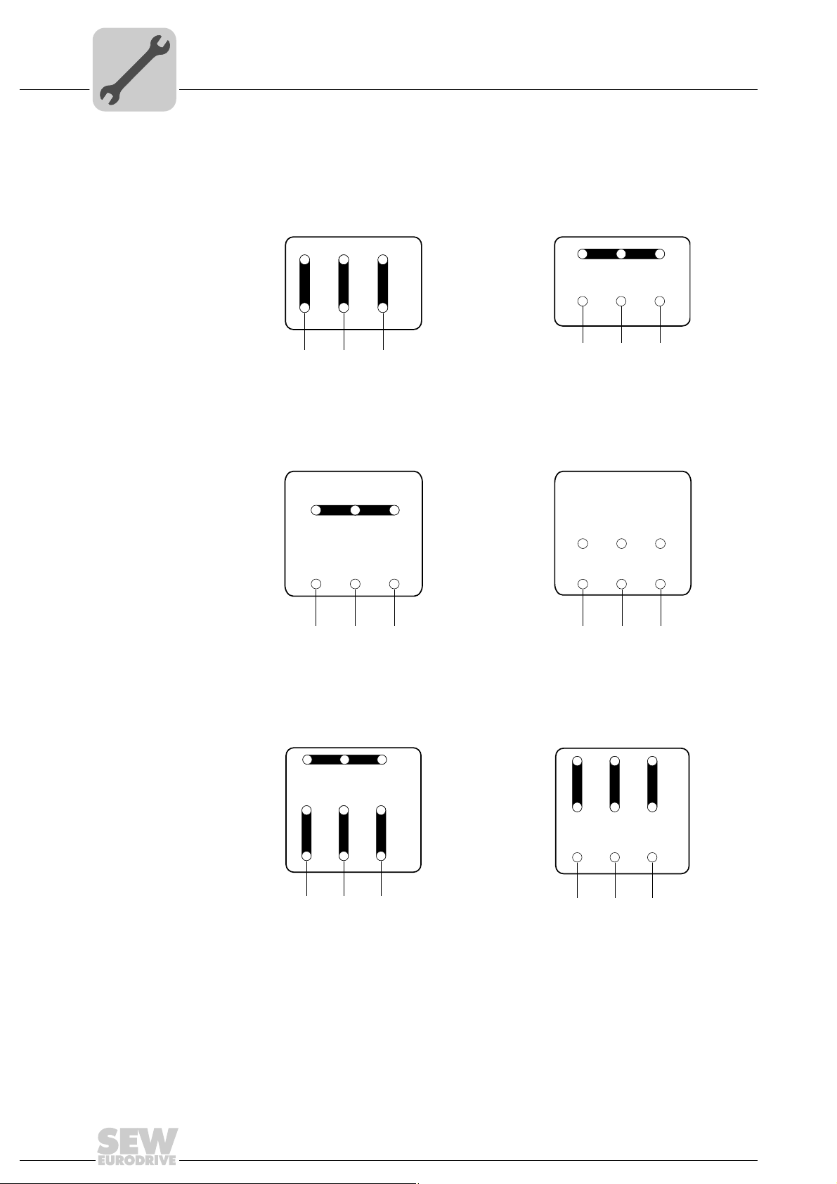
4.3.2 Installation
Installation
Electrical installation
Connect the inverter as shown in the following wiring diagrams. Ensure proper wiring in
the motor terminal box. Two basic connections are distinguished: Star connection and
delta connection. It is essential that you make sure that the motor is connected with the
voltage source in such a way that it is supplied with the proper operating voltage. You
find more information in the figure in section "Connection in the motor terminal box"
(page 24).
It is recommended that you use a 4-core PVC-insulated and shielded cable as the power
cable. Route this cable according to the applicable national regulations of the industry
sector as well as the rules and standards. Conductor end sleeves are required for connecting the power cables to the inverter.
®
The grounding terminal of each MOVITRAC
ually and directly to the ground busbar (mass) of the installation site (via filter, if available). Do not loop the ground connections of MOVITRAC
verter to the other. Neither route the ground connections to the inverters from other inverters. The impedance of the ground circuit must comply with the local safety regulations of the industry sector. To comply with UL regulations, all ground connections must
be designed with UL-listed crimping type ring cable lugs.
LTE-B inverter must be connected individ-
®
LTE-B inverters from one in-
4
Permitted voltage
supply systems
Line contactors and line fuses
Line contactors Use only line contactors in utilization category AC-3 (EN 60947-4-1).
Line fuses Fuse types:
• Voltage supply systems with grounded star point
®
MOVITRAC
directly grounded star point.
• Voltage supply systems with non-grounded star point
Operation on voltage supply systems with non-grounded star point (for example IT
systems) is also permitted. For this purpose, SEW-EURODRIVE recommends to use
an earth-leakage monitor according to the pulse-code measurement principle. Using
these devices avoids the earth-leakage monitor from tripping by mistake due to the
missing capacitance to ground of the inverter.
• Outer conductor grounded voltage supply systems
On voltage supply systems, the inverters may only be operated with a maximum
phase-to-ground AC voltage of 300 V.
It is important that a minimum time interval of 120 seconds is adhered to between two
voltage supply system activations.
• Line protection types in operation classes gL./ gG:
LTE-B inverters are designed for operation on TN and TT systems with
– Nominal fusing voltage ≥ nominal line voltage
– The nominal fusing current must be designed for at least 100% of the nominal in-
verter current depending on the inverter utilization.
• Power circuit breaker with characteristics B, C:
– Nominal circuit breaker voltage ≥ nominal line voltage
– The nominal currents of the power circuit breakers must be 10% higher than the
nominal inverter current.
Operating Instructions – MOVITRAC® LTE-B
23
4
W2
U2
U1UV1
W1
V2
V W
Installation
Electrical installation
Connection in the
motor terminal box
Connection types for motors: star, delta, double star, or star according to NEMA. The
nameplate of the motor indicates the nominal voltage for the connection type that has to
match the operating voltage of the MOVITRAC
R13
®
LTE-B inverter.
W2 U2
V2
U1UV1 W1
V W
Low voltage ∆ High voltage 댴
R76
T6 T4 T5
W2 U2 V2
T9 T7 T8
U3 V3
W3
T1 T2 T3
V1 W1
U1
T6 T4 T5
W2 U2 V2
T9 T7
W3 U3 V3
T1 T2 T3
U1L1V1 W1
T8
DR/DT/DV
L1
L2 L1
Low voltage
댴댴 High voltage 댴
T4 T5 T6
U2 V2 W2
T7 T8
V3
U3
T1 T2
U1
V1
U
V W
Low voltage
댴댴 High voltage 댴
T9
W3
T3
W1
L2 L1
T4 T5 T6
U2 V2 W2
T7 T8 T9
V3
U3
T1 T2 T3
V1
U1
U
V W
W3
W1
24
Operating Instructions – MOVITRAC® LTE-B
 Loading...