

SEW Movitrac B, Movitrac MC07B Operation Instructions Manual
Drive Technology \ Drive Automation \ System Integration \ Services
Operating Instructions
MOVITRAC
Edition 05/2013 20145756 / EN
®
B

SEW-EURODRIVE—Driving the world

Contents
Contents
1 General information ............................................................................................ 8
1.1 About this documentation .......................................................................... 8
1.2 Structure of the safety notes ....................................................................... 8
1.2.1 Meaning of the signal words........................................................ 8
1.2.2 Structure of the section-related safety notes ............................... 8
1.2.3 Structure of the embedded safety notes...................................... 8
1.3 Rights to claim under limited warranty ........................................................ 9
1.4 Exclusion of liability..................................................................................... 9
1.5 Copyright..................................................................................................... 9
1.6 Product names and trademarks.................................................................. 9
2 Safety notes....................................................................................................... 10
2.1 Preliminary information ............................................................................. 10
2.2 General information .................................................................................. 10
2.3 Target group ............................................................................................. 11
2.4 Designated use ......................................................................................... 11
2.4.1 Safety functions ......................................................................... 12
2.4.2 Document content...................................................................... 12
2.5 Other applicable publications.................................................................... 12
2.6 Transport/storage...................................................................................... 12
2.7 Installation................................................................................................. 13
2.8 Electrical connection ................................................................................. 13
2.9 Safe disconnection.................................................................................... 13
2.10 Operation .................................................................................................. 14
2.11 Unit temperature ....................................................................................... 14
3 Unit structure..................................................................................................... 15
3.1 Type designation....................................................................................... 15
3.2 Nameplate................................................................................................. 15
3.3 Scope of delivery ...................................................................................... 16
3.4 Sizes 0XS / 0S / 0L ................................................................................... 17
3.5 Sizes 1 / 2S / 2.......................................................................................... 18
3.6 Size 3 ........................................................................................................ 19
3.7 Sizes 4 / 5 ................................................................................................. 20
4 Installation ......................................................................................................... 21
4.1 Installation notes for basic unit – mechanical aspects .............................. 21
4.1.1 Minimum clearance and mounting position ............................... 21
Operating Instructions – MOVITRAC® B
3

Contents
4.2 Installation notes for basic unit – electrical aspects .................................. 22
4.2.1 Recommended tools.................................................................. 22
4.2.2 UL-compliant installation............................................................ 22
4.2.3 EMC-compliant installation ........................................................ 24
4.2.4 Shield terminals ......................................................................... 24
4.2.5 Wiring diagram........................................................................... 29
4.2.6 Requirements for cold plate installation – size 0 only................ 29
4.2.7 Deactivating the EMC capacitors – size 0 only.......................... 30
4.2.8 Separate cable ducts................................................................. 31
4.2.9 Operation on IT systems............................................................ 31
4.2.10 Utilization category of contactors............................................... 32
4.2.11 Required cross sections ............................................................ 32
4.2.12 Cable lengths for individual drives ............................................. 32
4.2.13 Unit output ................................................................................. 32
4.2.14 Switched inductances................................................................ 32
4.2.15 PE supply system connection according to EN 61800-5-1........ 32
4.2.16 Interference emission ................................................................ 33
4.2.17 Digital outputs ............................................................................ 33
4.3 Installing accessories and options – mechanical aspects......................... 33
4.3.1 Attaching the front modules....................................................... 33
4.3.2 PTC braking resistors BW1 / BW3 with FKB10B....................... 34
4.3.3 Flat-design resistors with FKB11B / FKB12B / FKB13B and
FHS11B / FHS12B / FHS13B .................................................... 35
4.4 Installing accessories and options – electrical aspects............................. 35
4.4.1 Braking resistor connection ....................................................... 35
4.4.2 Connecting braking resistor BW..-P / BW..-T / BW.. to X3 / X2. 36
4.4.3 Braking resistor installation........................................................ 37
4.4.4 ND line choke ............................................................................ 37
4.4.5 NF line filters.............................................................................. 37
4.4.6 ULF11A folding ferrites.............................................................. 38
4.4.7 HF output filters ......................................................................... 38
4.4.8 HD output chokes ...................................................................... 39
4.4.9 FKE12B / FKE13B EMC-modules ............................................. 40
4.4.10 Connection of the regenerative power supply unit..................... 42
4.4.11 Connection of RS485 interface.................................................. 44
4.4.12 System bus connection (SBus 1)............................................... 44
4.4.13 Setpoint adjuster connection ..................................................... 50
4.4.14 Connection of the interface adapter option UWS21B ................ 51
4.4.15 Built-in encoder EI7C connection .............................................. 53
4.4.16 Line protection and earth-leakage circuit breaker...................... 53
4.4.17 TF thermistor and TH bimetallic switch...................................... 53
4.4.18 Brake rectifier connection .......................................................... 54
4.4.19 Installation of FIO11B/21B, FSC11B/12B, FSE24B, DFP21B... 55
4
Operating Instructions – MOVITRAC® B

Contents
5 Startup................................................................................................................ 58
5.1 General startup instructions ...................................................................... 58
5.1.1 Requirements ............................................................................ 58
5.1.2 Hoist applications....................................................................... 58
5.2 Preliminary work and resources................................................................ 58
5.2.1 Preliminary work and tools for startup with factory setting......... 59
5.2.2 Preliminary work and tools for startup with keypad or with PC.. 59
5.3 Keypads .................................................................................................... 60
5.3.1 FBG11B – Basic keypad............................................................ 60
5.3.2 DBG60B – Advanced keypad.................................................... 66
5.4 MOVITOOLS
5.5 Short description of important startup steps ............................................. 74
5.5.1 Procedure .................................................................................. 74
5.5.2 Notes ......................................................................................... 74
5.5.3 Restoring the factory settings (P802) ........................................ 75
5.5.4 Adjusting the PWM frequency (P86x)........................................ 75
5.5.5 Parameterizing the inverter address (SBus / RS485 / fieldbus)
5.5.6 Setting the control mode (P700)................................................ 75
5.5.7 Application type specification..................................................... 75
5.5.8 Selection of operating mode (4-quadrant operation P82x)........ 75
5.5.9 Setpoint specification (P10x) ..................................................... 76
5.5.10 Protection functions ................................................................... 76
5.5.11 Specification of system limits..................................................... 77
5.5.12 Activating the energy-saving function (P770) ............................ 77
5.5.13 Activating the technology functions ........................................... 77
5.5.14 Settings for low motor speeds (P32x)........................................ 77
5.5.15 Determining the assignment of digital inputs (P60x) ................. 77
5.5.16 Setting the brake function (P73x) .............................................. 77
5.6 Starting the motor in manual mode........................................................... 78
5.6.1 Analog setpoint specification ..................................................... 78
5.6.2 Fixed setpoints........................................................................... 80
5.7 PI controller (P25x) ................................................................................... 82
5.8 Master-slave operation (P750).................................................................. 82
5.9 Group drive ............................................................................................... 82
5.10 Startup of explosion-proof AC asynchronous motors of
category 2 (94/9/EC)................................................................................. 82
5.11 Communication and unit profile ................................................................ 84
5.11.1 Process data.............................................................................. 85
5.11.2 Process data configuration ........................................................ 87
5.11.3 Process data description ........................................................... 88
5.11.4 Sequence control....................................................................... 94
5.11.5 Monitoring functions................................................................. 104
5.11.6 Setting the inverter parameters ............................................... 105
5.11.7 Notes on parameterization....................................................... 116
®
MotionStudio engineering software .................................. 73
(P81x) ........................................................................................ 75
Operating Instructions – MOVITRAC® B
5

Contents
5.12 External setpoint selection ...................................................................... 117
5.12.1 Setpoint direction ..................................................................... 117
5.12.2 Setpoint speed......................................................................... 117
5.12.3 Enabling the direction of rotation with RS485 or SBus ............ 117
5.12.4 Startup for MBG11A setpoint adjuster ..................................... 118
5.13 Overview of parameters.......................................................................... 118
6 Operation ......................................................................................................... 125
6.1 Data backup............................................................................................ 125
6.1.1 Data backup using FBG11B .................................................... 125
6.1.2 Data backup using DBG60B.................................................... 125
6.1.3 Data backup using UBP11A .................................................... 126
6.1.4 Data backup using MOVITOOLS
6.2 Status displays........................................................................................ 128
6.2.1 Basic unit / FBG11B keypad.................................................... 128
6.2.2 Status of digital inputs / outputs............................................... 129
6.3 Return codes (r19 – r38)......................................................................... 130
6.4 DBG60B keypad ..................................................................................... 131
6.4.1 Basic displays.......................................................................... 131
6.4.2 Information messages ............................................................. 132
6.4.3 Functions of the DBG60B keypad ........................................... 133
®
MotionStudio .................... 127
7 Service / list of faults ...................................................................................... 136
7.1 Device information .................................................................................. 136
7.1.1 Fault memory........................................................................... 136
7.1.2 Switch-off responses ............................................................... 136
7.1.3 Reset ....................................................................................... 137
7.2 List of faults (F00 – F113) ....................................................................... 137
7.3 SEW electronics service ......................................................................... 142
7.3.1 Hotline...................................................................................... 142
7.3.2 Send in for repair ..................................................................... 142
7.4 Extended storage.................................................................................... 142
7.5 Disposal .................................................................................................. 143
8 Technical data ................................................................................................. 144
8.1 Technical data of the basic unit .............................................................. 144
8.1.1 CE marking, UL approval and C-Tick ...................................... 144
8.1.2 General technical data............................................................. 145
8.1.3 Technical data of MOVITRAC
8.1.4 Technical data of MOVITRAC
8.1.5 Technical data of MOVITRAC
8.1.6 MOVITRAC
8.1.7 MOVITRAC
®
B electronics data .............................................. 168
®
B electronics data for functional safety.............. 169
®
B, 3 × 400 V AC .................... 147
®
B, 3 × AC 230 V .................... 156
®
B, 1 × AC 230 V .................... 164
6
Operating Instructions – MOVITRAC® B

Contents
8.2 Technical data for accessories and options ........................................... 170
8.2.1 Keypads................................................................................... 170
8.2.2 Interface adapters.................................................................... 176
8.2.3 Front modules.......................................................................... 180
8.2.4 Fieldbus connection................................................................. 188
8.2.5 MOVI-PLC
8.2.6 Switched-mode power supply UWU52A.................................. 204
8.2.7 Regenerative power supply ..................................................... 205
8.2.8 FHS11B/12B/13B support rail mounting.................................. 212
8.3 Technical data for braking resistors, chokes and filters .......................... 214
8.3.1 Braking resistors...................................................................... 214
8.3.2 Line chokes ND ...................................................................... 225
8.3.3 NF line filter.............................................................................. 228
8.3.4 ULF11A folding ferrites............................................................ 230
8.3.5 HD output chokes .................................................................... 231
8.3.6 HF... output filter ...................................................................... 234
8.3.7 EMC module FKE12B / FKE13B ............................................. 238
®
controller ............................................................. 198
9 Declaration of conformity............................................................................... 240
9.1 MOVITRAC
®
........................................................................................... 240
10 Address list...................................................................................................... 241
Index................................................................................................................. 253
Operating Instructions – MOVITRAC® B
7
1
General information
About this documentation
1 General information
1.1 About this documentation
The documentation is an integral part of the product and contains important information
on operation and service. The documentation is written for all employees who install,
startup, and service this product.
The documentation must be accessible and legible. Make sure that persons responsible
for the system and its operation, as well as persons who work independently on the unit,
have read through the documentation carefully and understood it. If you are unclear
about any of the information in this documentation, or if you require further information,
contact SEW-EURODRIVE.
1.2 Structure of the safety notes
1.2.1 Meaning of the signal words
The following table shows the grading and meaning of the signal words for safety notes,
notes on potential risks of damage to property, and other notes.
Signal word Meaning Consequences if disregarded
DANGER Imminent danger Severe or fatal injuries
WARNING Possible dangerous situation Severe or fatal injuries
CAUTION Possible dangerous situation Minor injuries
NOTICE Possible damage to property Damage to the drive system or its envi-
INFORMATION Useful information or tip: Simpli-
fies the handling of the drive
system.
1.2.2 Structure of the section-related safety notes
Section-related safety notes do not apply to a specific action, but to several actions pertaining to one subject. The used symbols indicate either a general or a specific hazard.
This is the formal structure of a section-related safety note:
SIGNAL WORD
Type and source of danger.
Possible consequence(s) if disregarded.
• Measure(s) to prevent the danger.
1.2.3 Structure of the embedded safety notes
Embedded safety notes are directly integrated in the instructions just before the description of the dangerous action.
ronment
–
This is the formal structure of an embedded safety note:
• SIGNAL WORD Nature and source of hazard.
Possible consequence(s) if disregarded.
– Measure(s) to prevent the danger.
8
Operating Instructions – MOVITRAC® B

Rights to claim under limited warranty
1.3 Rights to claim under limited warranty
General information
1
A requirement of fault-free operation and fulfillment of any rights to claim under limited
warranty is that you adhere to the information in the MOVITRAC
Read the documentation before you start working with the unit!
1.4 Exclusion of liability
You must comply with the information contained in the MOVITRAC® B documentation
to ensure safe operation of MOVITRAC
acteristics and performance requirements. SEW-EURODRIVE assumes no liability for
injury to persons or damage to equipment or property resulting from non-observance of
the documentation. In such cases, any liability for defects is excluded.
1.5 Copyright
© 2013 – SEW-EURODRIVE. All rights reserved.
Unauthorized duplication, modification, distribution or any other use of the whole or any
part of this documentation is strictly prohibited.
1.6 Product names and trademarks
®
B documentation.
®
B and to achieve the specified product char-
The brands and product names contained within this publication are trademarks or registered trademarks of the titleholders.
Operating Instructions – MOVITRAC® B
9

2
Safety notes
Preliminary information
2 Safety notes
The following basic safety notes must be read carefully to prevent injury to persons and
damage to property. The operator must ensure that the basic safety notes are read and
adhered to. Make sure that persons responsible for the plant and its operation, as well
as persons who work independently on the unit, have read through the operating instructions carefully and understood them. If you are unclear about any of the information in
this documentation, or if you require further information, please contact SEWEURODRIVE.
2.1 Preliminary information
The following safety notes predominantly refer to the use of frequency inverters. Additionally, when using drives with motors or gearmotors, observe the corresponding safety
notes in the respective operating instructions.
Please also observe the supplementary safety notes in the individual sections of this
publication.
2.2 General information
During operation, frequency inverters can have live, bare parts according to their degree
of protection.
• All work related to transportation, storage, installation, assembly, connection,
startup, maintenance and repair may only be carried out by qualified specialists, in
strict observance of:
– The pertinent detailed operating instructions
– The warning and safety signs on the motor or gearmotor
– All other project planning documents, operating instructions and wiring diagrams
related to the drive
– System-specific regulations and requirements
– The national/regional regulations governing safety and accident prevention
• Never install damaged products.
• Submit a complaint to the shipping company immediately in the event of damage.
Removing covers without authorization, improper use as well as incorrect installation or
operation may result in severe injuries to persons or damage to machinery.
This document includes further information.
10
Operating Instructions – MOVITRAC® B

2.3 Target group
Any mechanical work may only be performed by adequately qualified personnel. Qualified personnel in this context are persons who are familiar with the setup, mechanical
installation, troubleshooting and maintenance for this product. Further, they are qualified
as follows:
• Training in mechanical engineering, e.g. as a mechanic or mechatronics technician
• They are familiar with these operating instructions.
Any electronic work may only be performed by adequately qualified electricians. Quali-
fied electricians in this context are persons who are familiar with the electronic installation, startup, troubleshooting and maintenance for this product. Further, they are qualified as follows:
• Training in electrical engineering, e.g. as an electrician or mechatronics technician
• They are familiar with these operating instructions.
All work in further areas of transportation, storage, operation and waste disposal must
only be carried out by persons who are trained appropriately.
(final examinations must have been passed).
(final examinations must have been passed).
Safety notes
Target group
2
2.4 Designated use
Frequency inverters are components for controlling asynchronous AC motors. Frequency inverters are components intended for installation in electrical systems or machines. Never connect capacitive loads. Operation with capacitive loads results in overvoltages and may destroy the unit.
The following standards apply, if the frequency inverters are marketed in the EU/EFTA:
• In case of installation in machines, startup of the inverters (meaning the start of
proper use) is prohibited until it is determined that the machine meets the requirements stipulated in Directive 2006/42/EC (machine directive); observe EN 60204.
• Startup (i.e. the start of designated use) is only permitted under observance of the
EMC (2004/108/EC) directive.
• The frequency inverters comply with the requirements of the Low Voltage Directive
2006/95/EC. The harmonized standards of the EN 61800-5-1/DIN VDE T105 series
in connection with EN 60439-1/VDE 0660 part 500 and EN 60146/VDE 0558 are applied to these frequency inverters.
Observe the technical data and the connection requirements specified on the nameplate
and the operating instructions.
Operating Instructions – MOVITRAC® B
11

2
2.4.1 Safety functions
2.4.2 Document content
Safety notes
Other applicable publications
Frequency inverters from SEW-EURODRIVE must not perform any safety functions unless the inverters are subordinate to other safety systems.
Use higher-level safety systems to ensure protection of equipment and personnel.
When using the "Safe stop" function, you must observe the following publications:
•MOVITRAC
This documentation is available via "Documentation \ Software \ CAD" on the SEW-
EURODRIVE website.
This publication contains conditions and amendments related to MOVITRAC
safety-oriented applications.
The system comprises a frequency inverter with asynchronous motor and safety-tested
external disconnecting device.
®
B / functional safety
®
B in
2.5 Other applicable publications
This document supplements the MOVITRAC® B operating instructions and limits the application notes according to the following information.
It can only be used in conjunction with the following publications:
•MOVITRAC
• The respective manual of the used option card
®
B compact operating instructions
2.6 Transport/storage
Inspect the shipment for any damage that may have occurred in transit as soon as you
receive the delivery. Inform the shipping company immediately about any damage. It
may be necessary to preclude startup. Observe the climate conditions according to
chapter "General technical data (page 145)".
12
Operating Instructions – MOVITRAC® B

2.7 Installation
Safety notes
Installation
The units must be installed and cooled according to the regulations and specifications
in this documentation.
Protect the frequency inverters from excessive strain. Do not twist any components and
do not modify the insulation spaces. Do not touch any electronic components or contacts.
Frequency inverters contain components that can easily be damaged by electrostatic
energy and improper handling. Electric components must not be mechanically damaged
or destroyed.
The following applications are prohibited unless explicitly permitted:
• Use in potentially explosive atmospheres.
• Use in areas exposed to harmful oils, acids, gases, vapors, dust, radiation, etc. (frequency inverter may only be operated in climate class 3K3 to EN 60721-3-3)
• Use in non-stationary applications that are subject to mechanical vibration and shock
loads in excess of the requirements in EN 61800-5-1.
2
2.8 Electrical connection
Observe the applicable national accident prevention guidelines when working on live
frequency inverters (e.g. BGV A3 for Germany).
During installation, observe the specifications regarding cable cross sections, fusing and
protective conductor connection. This publication contains additional information.
In this documentation, you will find notes on EMC-compliant installation, such as shielding, grounding, arrangement of filters and routing of lines. The manufacturer of the system or machine is responsible for maintaining the limits established by EMC legislation.
Protective measures and protection devices must comply with the regulations in force
(e.g. EN 60204 or EN 61800-5-1).
Ground the unit.
2.9 Safe disconnection
The unit meets all requirements for reliable isolation of power and electronics connections in accordance with EN 61800-5-1. All connected circuits must also satisfy the requirements for safe disconnection to ensure reliable isolation.
Operating Instructions – MOVITRAC® B
13

2
2.10 Operation
Safety notes
Operation
Systems with integrated frequency inverters must be equipped with additional monitoring and protection devices, as applicable, according to the relevant safety guidelines
and regulations, such as legislation governing technical equipment, accident prevention
regulations, etc.
Do not touch live components or power connections until 10 minutes after disconnecting
the frequency inverters from the supply voltage because there may still be some
charged capacitors. Observe the corresponding labels on the frequency inverter.
Keep all covers and housings closed during operation.
The fact that the status LED and other display elements are no longer illuminated does
not indicate that the unit has been disconnected from the supply system and no longer
carries any voltage.
Mechanical blocking or internal safety functions of the unit can cause a motor standstill.
Eliminating the cause of the problem or performing a reset may result in the drive restarting automatically. If this is not permitted for the driven machine for safety reasons,
disconnect the unit from the supply system before correcting the fault.
2.11 Unit temperature
MOVITRAC® B frequency inverters are usually operated with braking resistors. The
braking resistors are usually installed on top of the control cabinet.
The braking resistors can reach a surface temperature of significantly more than 70 °C.
Never touch the braking resistors during operation or in the cool down phase once the
unit has been switched off.
14
Operating Instructions – MOVITRAC® B
3 Unit structure
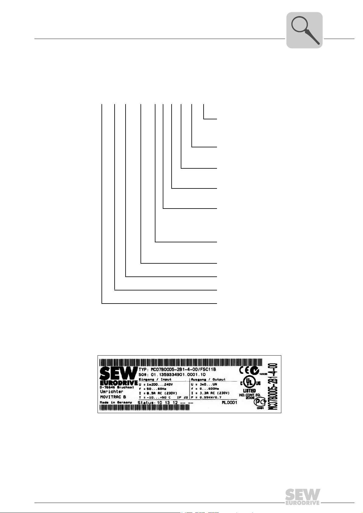
3.1 Type designation
The following diagram shows a type designation:
MC 07 B 0022- 2 B 1- 4- 00 /T
Unit structure
Type designation
Design
3
/T = Technology unit
/L = Paint
(partially coated pcb)
/S = SBus address 1
Design
Quadrants
Connection type 3 = 3-phase / 1 = 1-phase
Radio
interference
suppression
Supply voltage
Recommended
motor power
Version B
Series and generation
MOVITRAC
00 = Standard
S0 = Safe stop
4 = 4Q (with brake chopper)
0 = No suppression
A = Suppression C2
B = Suppression C1
2 = AC 200 – 240 V
5 = AC 380 – 500 V
0022 = 2.2 kW
®
type
3.2 Nameplate
The following figure shows a nameplate:
Input U Nominal line voltage T Ambient temperature
I Nominal line current, 100% operation P
f Nominal line frequency
Output U Output voltage 100% operation
I Nominal output current 100% operation
f Output frequency
The unit status is indicated above the lower barcode. It documents the unit’s hardware and software states.
Operating Instructions – MOVITRAC® B
Recommended motor power 100% operation
motor
3185547659
15
3
"#!#%!#
#!"#%#
"#$!"&"#%&"
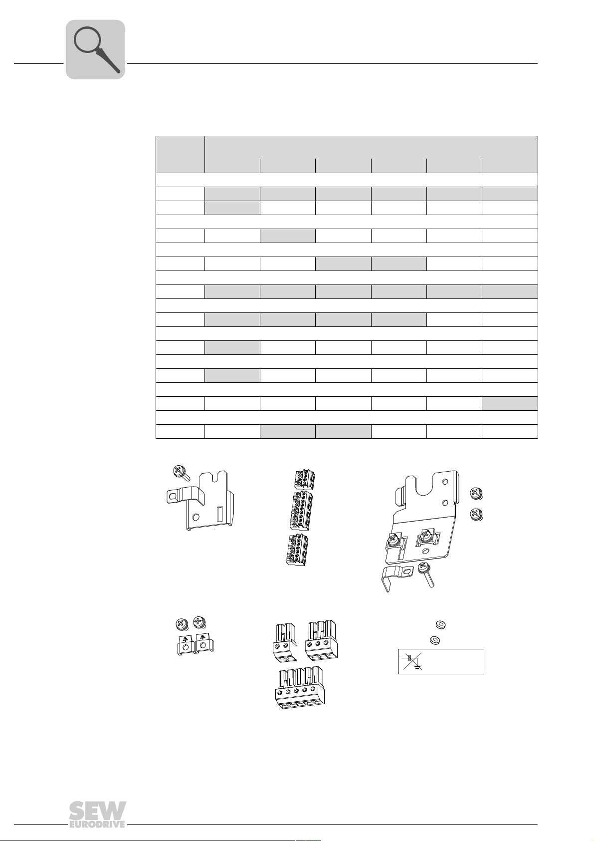
3.3 Scope of delivery
Unit structure
Scope of delivery
The parts listed below are delivered in an accessory bag for each unit size.
Illustration no.
0XS, 0S, 0L 1 2S 2 3 4, 5
Shield plate for control electronics with clamps and screws
[1]
[3]
Shield plate for the power section without screws
Shield plate for the power section with screws
Connector for electronics terminals
[2]
Grounding terminals with screws
[4]
Connector for supply system (2 or 3-pole) and motor
[5]
Plastic insulation with sticker
[6]
Touch guard
Fixing straps
1x 1x 1x 1x 1x 1x
1x
1x
1x 1x
3x 3x 3x 3x 3x 3x
1x 1x 1x 1x
1x
1x
1x 1x
Size
1x
16
Operating Instructions – MOVITRAC® B
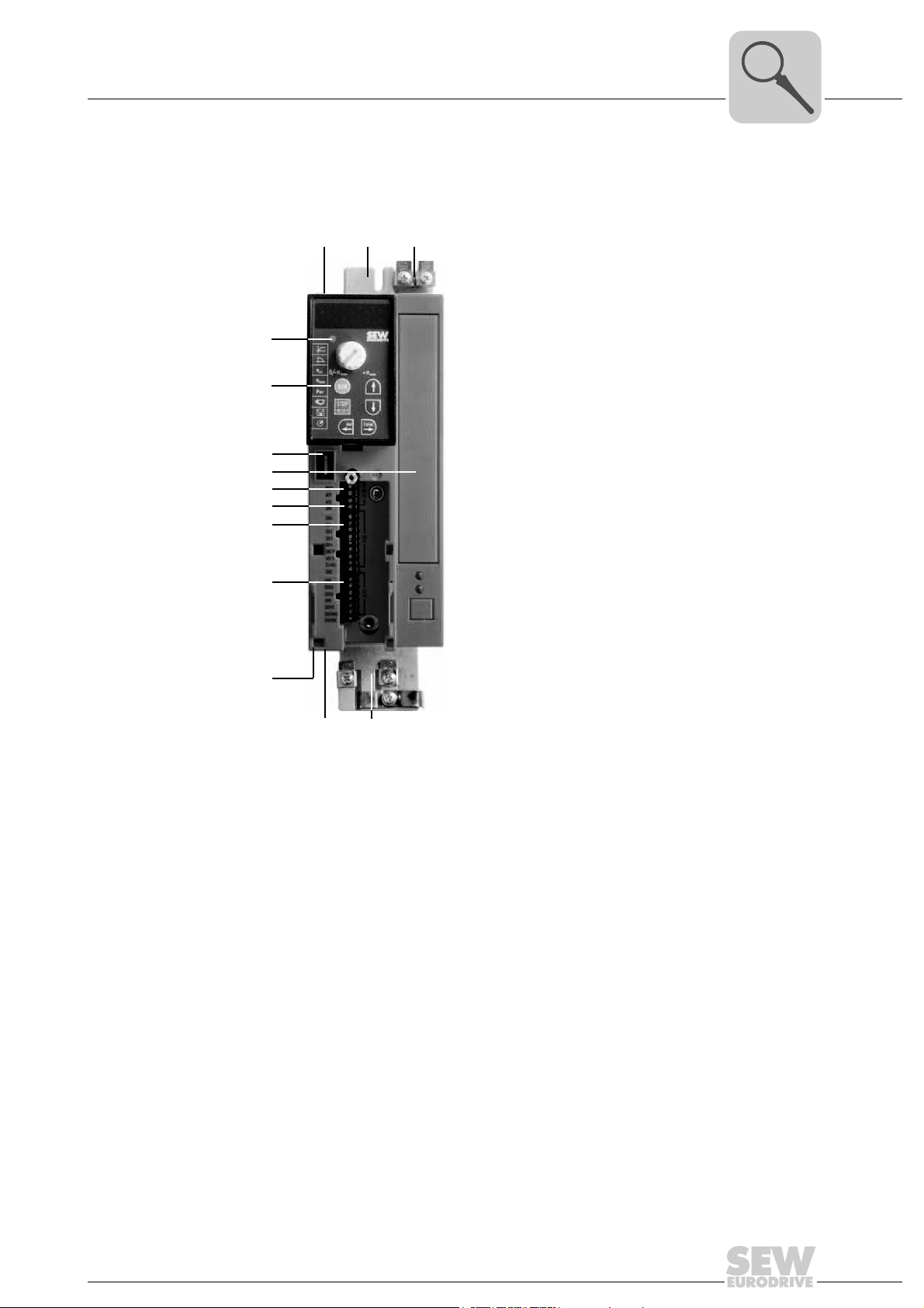
3.4 Sizes 0XS / 0S / 0L
Unit structure
Sizes 0XS / 0S / 0L
3
[14]
[13]
[12]
[11]
[10]
[9]
[8]
[7]
[6]
[1]
[2]
[3]
[4][5]
9007199279301643
[1] X1: Power supply connection:
3-phase: L1 / L2 / L3
1-phase: L / N
[2] Fixing strap
[3] PE connection
[4] Shield plate for motor cable, fixing strap underneath
[5] X2: Motor connection U / V / W / Brake connection +R / -R
[6] X17: Safety contact for safe stop
(only MC07B...-S0: sizes 0S / 0L, 400 / 500 V)
[7] X13: Digital outputs
[8] X12: Digital inputs
[9] X10: Analog input
[10] Switch S11 for V mA switchover analog input (with size 0XS and 0S behind the removal
connector)
[11] Option card slot (cannot be retrofitted / not for BG0XS)
[12] Connection for optional communication / analog module
[13] Optional keypad, inserted
[14] Status LED (visible without optional keypad)
Operating Instructions – MOVITRAC® B
17
3
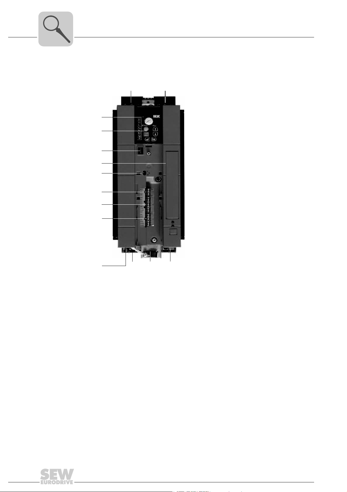
3.5 Sizes 1 / 2S / 2
Unit structure
Sizes 1 / 2S / 2
[2][1]
[14]
[13]
[12]
[11]
[10]
[9]
[8]
[7]
[4]
[1] X1: Power supply connection 3-phase: L1 / L2 / L3 / PE screw
[2] X4: Connection for DC link coupling –U
[3] X3: Braking resistor connection R+ / R– / PE
[4] Electronics shield clamp
[5] X2: Motor connection U / V / W / PE screw
[6] X17: Safety contact for safe stop (only 400 / 500 V)
[7] X13: Digital outputs
[8] X12: Digital inputs
[9] X10: Analog input
[10] Switch S11 for V-mA toggle analog input
[11] Space for option card (cannot be retrofitted)
[12] Connection for optional communication / analog module
[13] Optional keypad, inserted
[14] Status LED (visible without optional keypad)
[3][5][6]
9007199346901259
Z
+U
Z
18
Operating Instructions – MOVITRAC® B
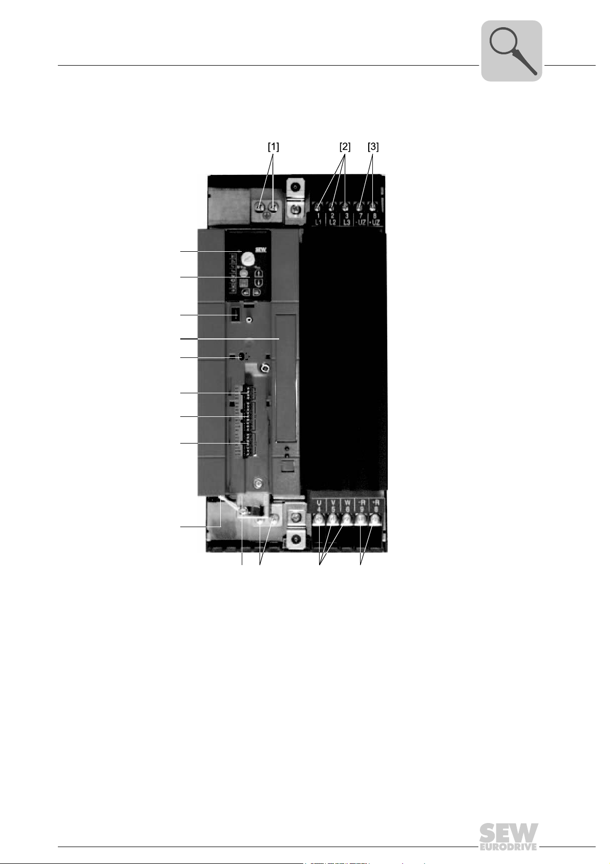
3.6 Size 3
[9]
[10]
[11]
[12]
[13]
[14]
[15]
[16]
[8]
[7]
[4][5][6]
Unit structure
Size 3
3
[1] X2: PE connection
[2] X1: Power supply connection 3-phase: 1/L1 / 2/L2 / 3/L3
[3] X4: Connection for DC link coupling –U
[4] X3: Braking resistor connection R+ (8) / R– (9) and PE connection
[5] X2: Motor connection U (4) / V (5) / W (6)
[6] X2: PE connection
[7] Electronics shield clamp
[8] X17: Safety contact for safe stop (only 400 / 500 V)
[9] X13: Digital outputs
[10] X12: Digital inputs
[11] X10: Analog input
[12] Switch S11 for V-mA toggle analog input
[13] Space for option card (cannot be retrofitted)
[14] Connection for optional communication / analog module
[15] Optional keypad, inserted
[16] Status LED (visible without optional keypad)
Operating Instructions – MOVITRAC® B
9007199346833675
+U
Z
Z
19
3
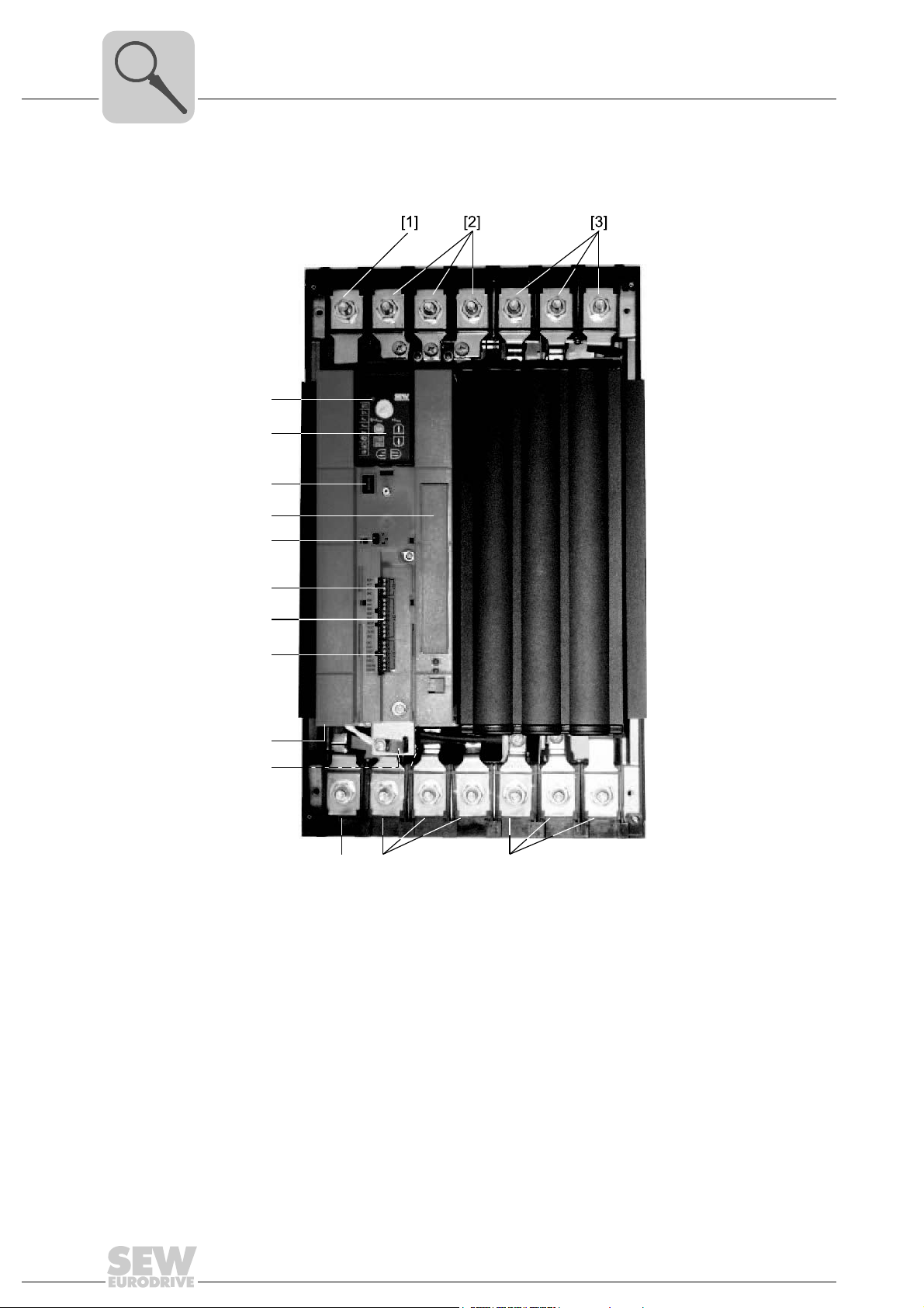
3.7 Sizes 4 / 5
Unit structure
Sizes 4 / 5
[16]
[15]
[14]
[13]
[12]
[11]
[10]
[9]
[8]
[7]
[6] [4][5]
9007199346827019
[1] X2: PE connection
[2] X1: Power supply connection 3-phase: 1/L1 / 2/L2 / 3/L3
[3] X4: DC link connection –U
[4] X3: Braking resistor connection R+ (8) / R– (9) and PE connection
[5] X2: Motor connection U (4) / V (5) / W (6)
[6] X2: PE connection
[7] Electronics shield clamp
[8] X17: Safety contact for safe stop (only 400 / 500 V)
[9] X13: Digital outputs
[10] X12: Digital inputs
[11] X10: Analog input
[12] Switch S11 for V-mA toggle analog input
[13] Space for option card (cannot be retrofitted)
[14] Connection for optional communication / analog module
[15] Optional keypad, inserted
[16] Status LED (visible without optional keypad)
/ +UZ and PE connection
Z
20
Operating Instructions – MOVITRAC® B
4 Installation
The surface temperatures of the heat sinks can exceed 70 °C.
Danger of burns.
• Do not touch the heat sink.
Installation
Installation notes for basic unit – mechanical aspects
DANGER
DANGER
Dangerous voltages present at cables and terminals.
Severe or fatal injuries from electric shock.
To prevent electric shocks due to stored charges:
• Disconnect the inverter from the supply system and wait 10 minutes before starting
to work on it.
• Use suitable measuring instruments to make sure that no voltage is present at cables and terminals.
4
4.1 Installation notes for basic unit – mechanical aspects
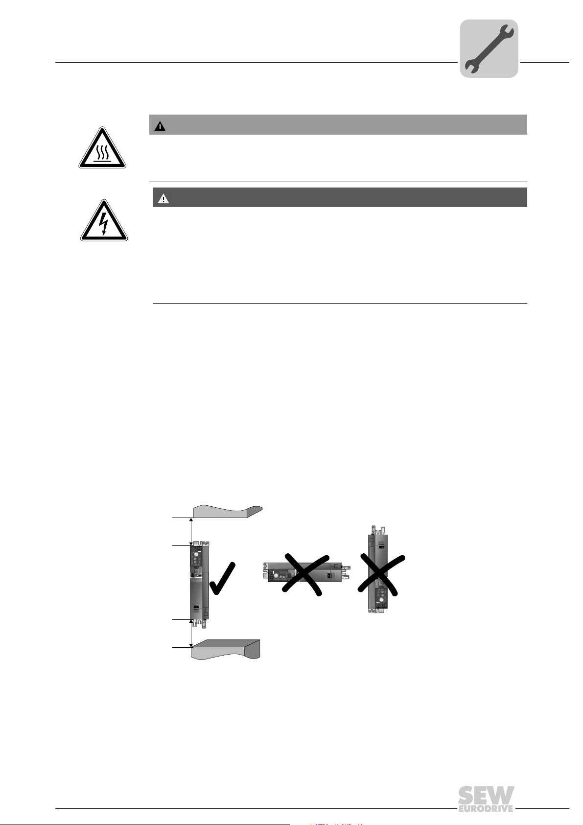
4.1.1 Minimum clearance and mounting position
• Leave 100 mm (3.94 in) clearance at the top and bottom of the housing for optimum
cooling. There is no need for clearance at the sides. You can line up the units directly
next to one another.
• It is important that air circulation is not impeded by cables and other installation material. Prevent the heated exhaust air from other units from blowing onto this unit.
• Install the units vertically only. You must not install them horizontally, tilted or upside
down.
• Proper heat dissipation of the rear side of the heat sink improves the thermal utilization of the unit.
100 mm
(3.94 in)
100 mm
(3.94 in)
Operating Instructions – MOVITRAC® B
648722187
21

4
Installation
Installation notes for basic unit – electrical aspects
4.2 Installation notes for basic unit – electrical aspects
4.2.1 Recommended tools
• Use a screwdriver with a 2.5 mm wide blade for connecting the electronics terminal
strip X10 / X12 / X13.
4.2.2 UL-compliant installation
Note the following points for UL-compliant installation:
• Only use copper cables with the following temperature characteristics:
–MOVITRAC
–MOVITRAC
• Necessary tightening torques of MOVITRAC
"Technical Data" (page 147).
• Operate the inverters on supply systems with a maximum phase-to-earth voltage of
AC 300 V only.
• The inverter can only be operated on IT systems if the phase-to-earth voltage of
AC 300 V cannot be exceeded either during operation or in case of a fault.
•MOVITRAC
tems which can supply maximum values in accordance with the following table. Only
use melting fuses. The performance data of the fuses must not exceed the values in
the following table.
®
B 0003 – 0300: Temperature range 60/75 °C
®
B 0370 und 0750: Temperature range 75 °C (167 °F)
®
B frequency inverters are only allowed to be operated on supply sys-
®
B power terminals: See chapter
22
Operating Instructions – MOVITRAC® B
Installation
Installation notes for basic unit – electrical aspects
4
Maximum values/fuses
The following maximum values/fuses must be observed for UL compliant installation:
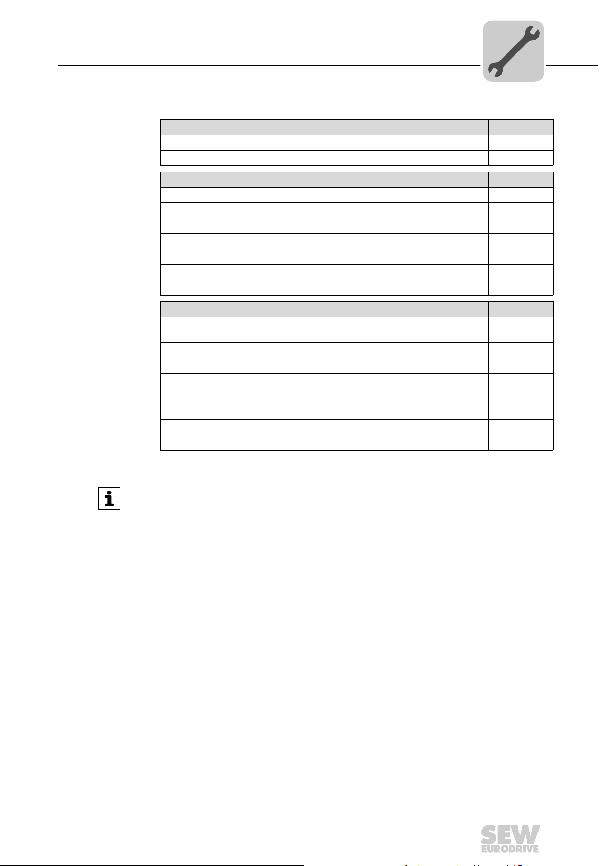
230 V units / 1-phase Max. line current Max. line voltage Fuses
0003 / 0004 / 0005 / 0008 AC 5000 A AC 240 V 15 A / 250 V
0011 / 0015 / 0022 AC 5000 A AC 240 V 30 A / 250 V
230 V units / 3-phase Max. line current Max. line voltage Fuses
0003 / 0004 / 0005 / 0008 AC 5000 A AC 240 V 15 A / 250 V
0011 / 0015 / 0022 AC 5000 A AC 240 V 20 A / 250 V
0037 AC 5000 A AC 240 V 30 A / 250 V
0055 / 0075 AC 5000 A AC 240 V 110 A / 250 V
0110 AC 5000 A AC 240 V 175 A / 250 V
0150 AC 5000 A AC 240 V 225 A / 250 V
0220 / 0300 AC 10000 A AC 240 V 350 A / 250 V
400/500 V units Max. line current Max. line voltage Fuses
0003 / 0004 / 0005 / 0008 /
0011 / 0015
0022 / 0030 / 0040 AC 5000 A AC 500 V 20 A / 600 V
0055 / 0075 AC 5000 A AC 500 V 60 A / 600 V
0110 AC 5000 A AC 500 V 110 A / 600 V
0150 / 0220 AC 5000 A AC 500 V 175 A / 600 V
0300 AC 5000 A AC 500 V 225 A / 600 V
0370 / 0450 AC 10000 A AC 500 V 350 A / 600 V
0550 / 0750 AC 10000 A AC 500 V 500 A / 600 V
AC 5000 A AC 500 V 15 A / 600 V
INFORMATION
Use only tested units with a limited output voltage (V
current (I ≤ 8 A) as an external DC 24 V voltage source.
UL certification does not apply to operation in voltage supply systems with a nongrounded star point (IT systems).
= DC 30 V) and limited output
max
Operating Instructions – MOVITRAC® B
23
4
[1]
4.2.3 EMC-compliant installation
Installation
Installation notes for basic unit – electrical aspects
• Shield all cables except for the power supply cable. For the motor cable, you can use
• When using shielded motor cables, e.g. prefabricated motor cables from SEW-
• Connect the shield by the shortest possible route and make sure it is grounded over
the HD.. option (output choke) instead of the shielding to meet the interference emission limit values.
EURODRIVE, you must keep the unshielded conductors between the shield and
connection terminal of the inverter as short as possible.
a wide area at both ends. If using double-shielded cables, ground the outer shield on
the inverter end and the inner shield at the other end.
• You can also use grounded sheet-metal ducts or metal pipes to shield the cables.
• Provide high frequency compatible grounding for the inverter and all additional units
INFORMATION
•MOVITRAC®B is a product that can cause electromagnetic interference according
• For detailed information on EMC-compliant installation, refer to the publication
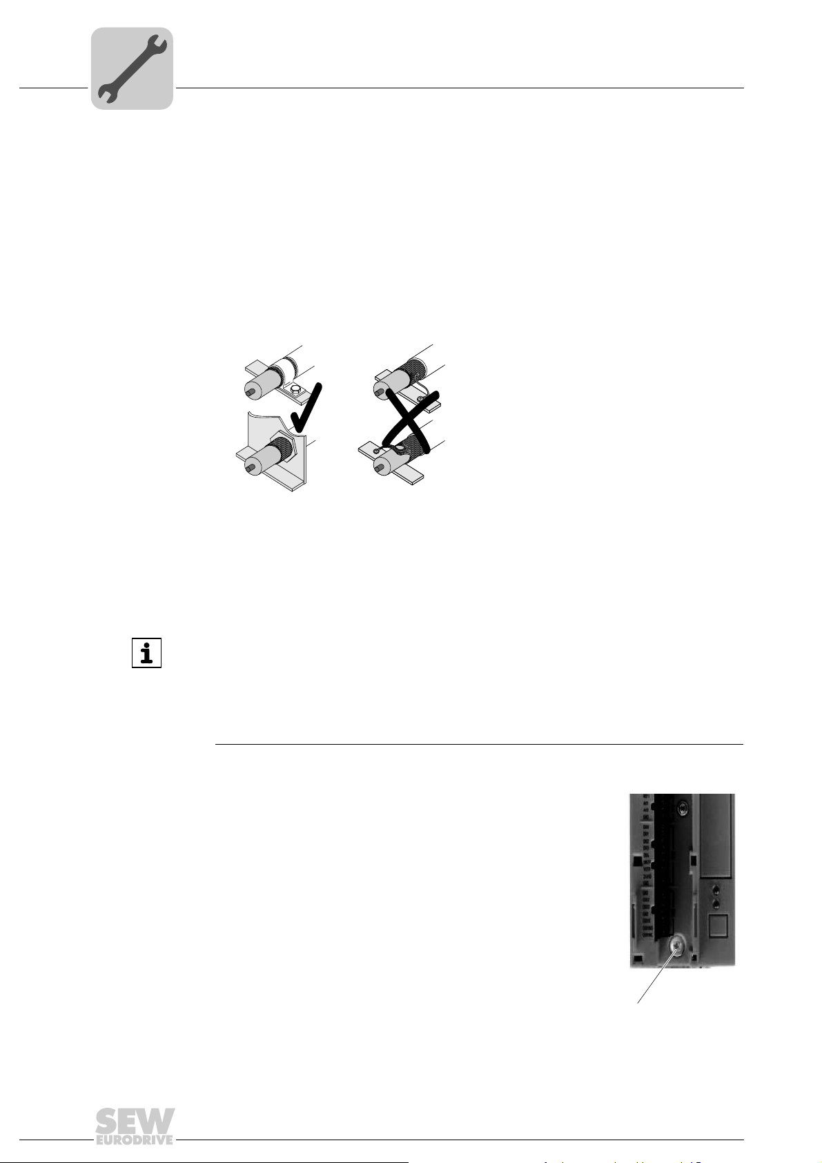
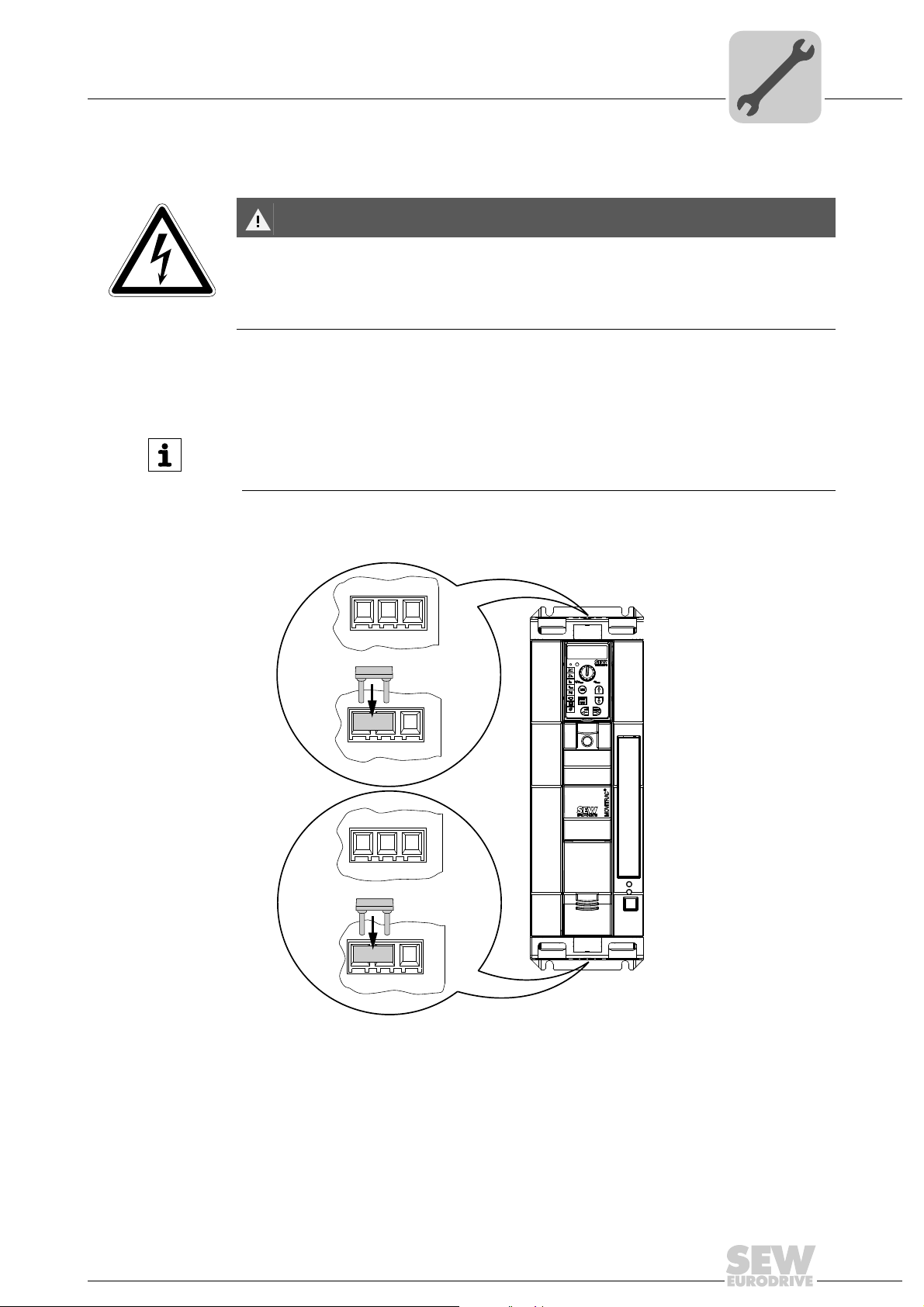
4.2.4 Shield terminals
Installation of
shield plate for
control electronics
(all sizes)
MOVITRAC
ics with a retaining screw as standard. Install the shield plate for
control electronics as follows:
1. Loosen the screw first [1].
2. Insert the shield clamp into the slot in the plastic housing.
3. Fasten the shield clamp.
9007199272247947
Install the power and control cables separately.
(wide area metal-on-metal contact between the unit housing and ground, e.g.
unpainted control cabinet mounting panel).
to EN 61800-3. In this case, it is recommended for the operator to take suitable
measures.
"Drive Engineering – Practical Implementation: EMC in Drive Engineering" from
SEW-EURODRIVE.
®
B includes a shield plate for the control electron-
24
Operating Instructions – MOVITRAC® B
Installation
Installation notes for basic unit – electrical aspects
4
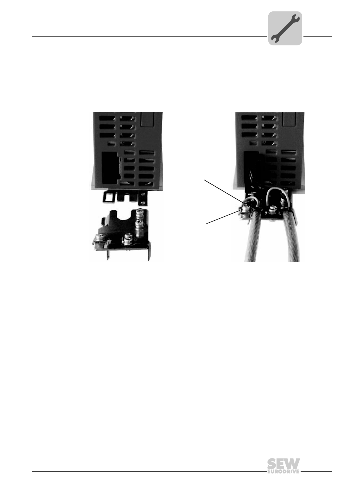
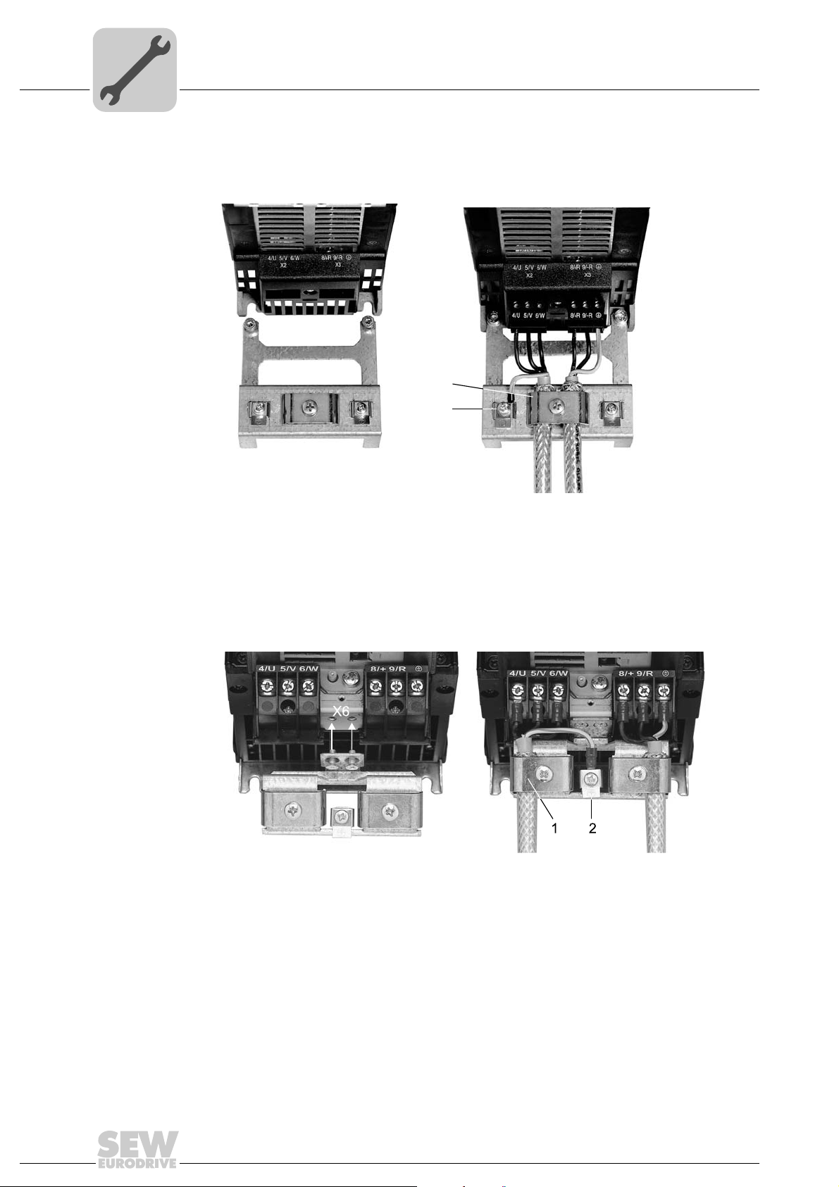
Installation of
shield plate for the
power section
Size 0 A shield plate for the power section with 2 retaining screws is supplied as standard with
The shield plate for the power section provides you with a very convenient way of installing the shield for the motor and braking resistor cables. Apply the shield and PE conductor as shown in the figures below.
MOVITRAC
Mount the shield plate for the power section using the two retaining screws.
®
B size 0.
[1]
[1] Shield plate
[2] PE connection
[2]
318334475
Operating Instructions – MOVITRAC® B
25
4
Installation
Installation notes for basic unit – electrical aspects
Size 1 A shield plate for the power section with 2 retaining screws is supplied as standard with
MOVITRAC
®
B size 1.
Mount the shield plate for the power section using the two retaining screws.
[1]
[2]
244986123
[1] Shield plate
[2] PE connection
Size 2S/2 A shield plate for the power section with 2 retaining screws is supplied as standard with
MOVITRAC
®
B size 2S/2.
Mount the shield plate for the power section using the two retaining screws. The illustration below shows size 2.
111752587
[1] Shield plate
[2] PE connection
Sizes 3 – 5 No shield plates for the power section are supplied with MOVITRAC
®
B sizes 3 to 5. Use
commercially available shield clamps for installing the shielding of motor and brake resistor cables. Apply the shield as closely as possible to the inverter.
26
Operating Instructions – MOVITRAC® B
Touch guard installation
Installation notes for basic unit – electrical aspects
DANGER
Uncovered power connections.
Severe or fatal injuries from electric shock.
• Install the touch guard according to the regulations.
• Never start the unit if the touch guard is not installed.
Installation
4
Size 2S SEW-EURODRIVE supplies 2 touch guards for the DC link and braking resistor termi-
nals as standard with MOVITRAC
MOVITRAC
®
B size 2S has degree of protection IP20.
®
B size 2S. When the touch guard is installed,
INFORMATION
When the touch guard is not installed, MOVITRAC® B size 2S has degree of protection
IP10.
Install the touch guard as shown in the illustration below.
IP10
X4
+U
-U
-U
PE
Z
Z
IP20
X4
+U
PE
Z
Z
IP10
X3
9/-R8/+R
PE
IP20
X3
9/-R8/+R
PE
9007199366497419
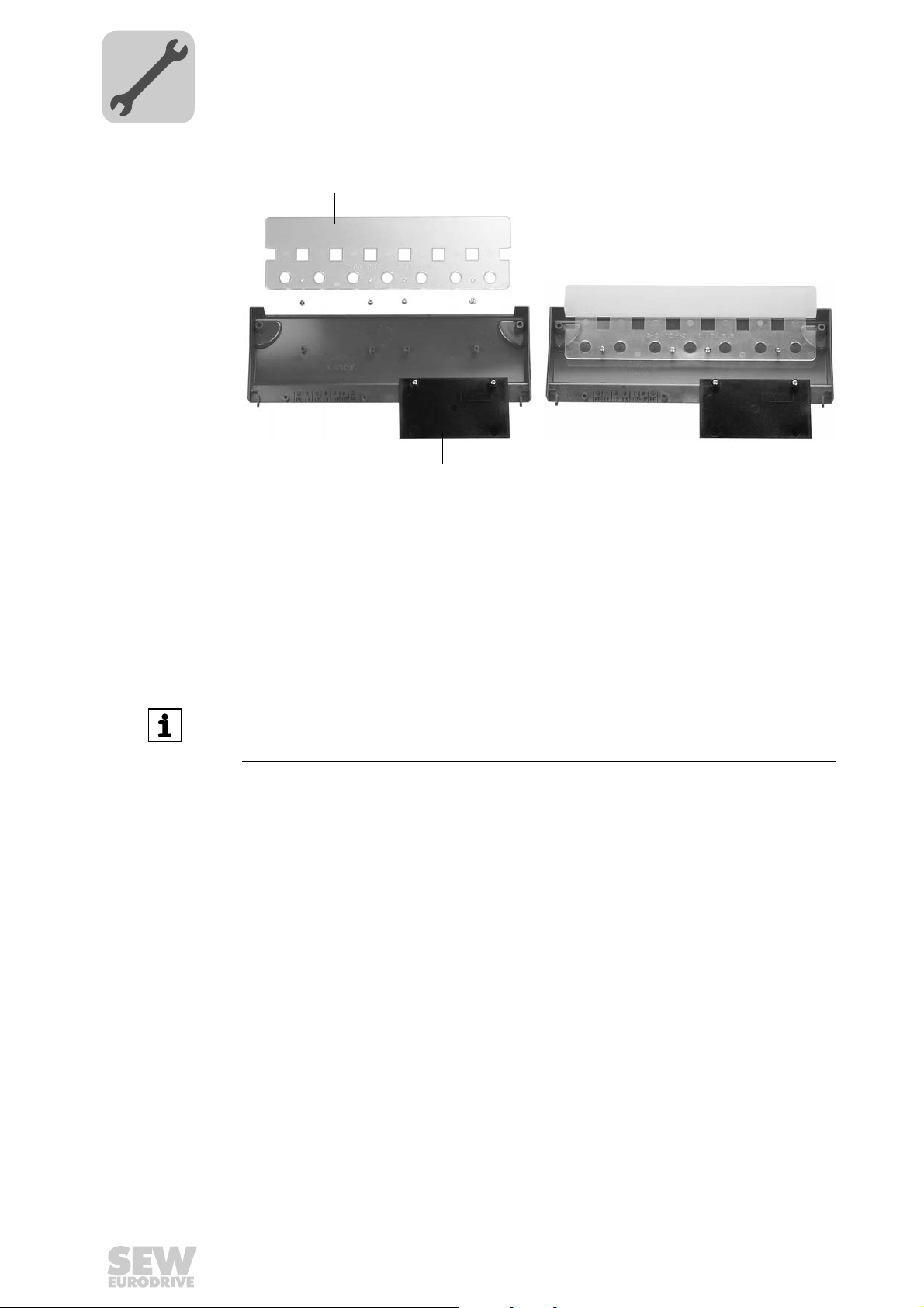
Sizes 4 / 5 Two touch guards with 8 retaining screws are supplied as standard with MOVITRAC
sizes 4 and 5.
Operating Instructions – MOVITRAC® B
®
B
27
4
[1]
[2]
[3]
Installation
Installation notes for basic unit – electrical aspects
Install the touch guard on both covers of the power section terminals.
188886667
[1] Cover
[2] Connection plate
[3] Screen (only for size 4)
MOVITRAC
®
B units of size 4 and 5 can only achieve degree of protection IP10 when
the following conditions are met:
• Touch guard is fully installed
• The shrink tubing is installed on all power section terminals (X1, X2, X3, X4)
INFORMATION
If the above conditions are not met, MOVITRAC® B inverters of size 4 and 5 have degree of protection IP00.
28
Operating Instructions – MOVITRAC® B
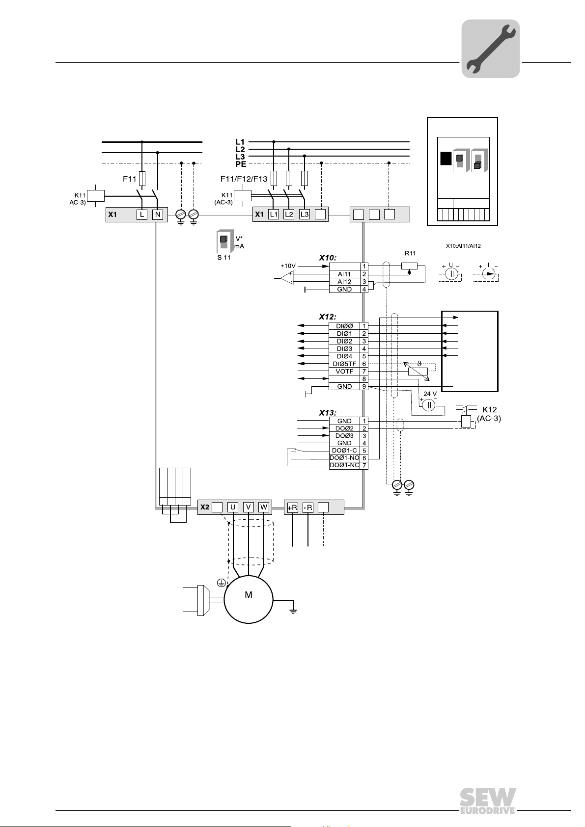
4.2.5 Wiring diagram
ON
OFF
ON
OFF
X45
X46
1
23456HL⊥
FSC11B
MOVITRAC® B
S1
7
S2
X44
-> Section "Connecting braking resistors
BW.. / BW..-T / BW..-P"
PE
X2
X3
PE X4
7
8
+U
Z
–U
Z
DGND
VO24
SOV24
SVI24
123
4
X17:
PE
PE
3 x AC 400/500 V / PE
3 x AC 230 V / PE
-> Section "Connecting
the brake rectifier"
X17 "Safe stop"
3 x 400 V:
5.5 – 75 kW, standard
3 x 400 V:
0.55 – 4.0 kW, MC07B..-S0
3 x 230 V:
3.7 – 30 kW, standard
3 x 230 V:
0.55 – 2.2 kW, MC07B..-S0
1 x AC 230 V / N / PE
[1]
[1][1]
L1
N
PE
Switchover
I signal -> U signal*
* = Factory setting
}
n13 = n11 + n12
REF1
24VIO
Enable/stop*
+24V input/output
(can be disabled with P808)
0 V – +10 V 0 (4) – 20 mA
Higher-level
controller
Digital
input
Digital
outputs
Reference f.
digital outputs
0 – 10 V*
0 – 20 mA; 4 – 20 mA
Ref. potential for analog signals
Error reset*
CW/stop
CCW/stop*
n11/n21*
n12/n22*
Supply voltage for TF/TH
Ref. potential for digital signals
Reference potential
Brake released*
Ready for operation*
Reference potential
Relay contact/fault*
Relay NO contact
Relay NC contact
[2]
PE
(
3-phase
Installation
Installation notes for basic unit – electrical aspects
4
[1] In sizes 1, 2S, and 2, there is no PE connection next to the power supply connection terminals and motor connection terminals
[2] The MC07B..-S0 unit type must always be supplied with external voltage.
4.2.6 Requirements for cold plate installation – size 0 only
Operating Instructions – MOVITRAC® B
[X1]/[X2]. Use the PE terminal next to the DC link connection [X4] (only size 1 – 5). For size 0, the plate is the PE connection.
X4 is only available in sizes 1 – 5. From size 3 onwards, there are two additional PE terminals.
The frequency inverter power loss can be dissipated via coolers that work with different
cooling media (air, water, oil, etc.). This can be useful, for example, in restricted instal-
29
4
4.2.7 Deactivating the EMC capacitors – size 0 only
Installation
Installation notes for basic unit – electrical aspects
lation spaces. When heeding the usual installation notes (40 °C/100 mm (3.94 in) space
above and below), cold-plate technology is not necessary.
A good thermal connection to the cooler is important for safe operation of the frequency
inverters:
• The contact area between cooler and frequency inverter has to be the size of the fre-
quency inverter cooling plate.
• Level contact surfaces are required, maximum deviation 0.05 mm (0.0002 in).
• Connect cooler and cooling plate with all necessary screw connections.
• The mounting plate must not exceed 70 °C during operation. This must be ensured
by the cooling medium.
• Cold plate installation is not possible with FHS or FKB.
DANGER
Severe or fatal injuries from electric shock.
• Disconnect the inverter from the power. Disconnect the DC 24 V supply and the line
voltage.
• Wait 10 seconds.
• Ensure that the unit is de-energized.
• Take appropriate measures to avoid electrostatic charges (use discharge strap,
conductive shoes, etc.) before removing the cover.
• Touch only the unit frame and the heat sink. Do not touch any electronic compo-
nents.
Only electricians are allowed to convert the unit. Once converted, the unit must be
marked with the sticker provided in the accessory bag.
Proceed as follows to deactivate the EMC capacitors in the MOVITRAC
inverter:
1. Open the unit:
– Remove all connectors.
– Remove the electronics shield clamp.
– Remove the housing retaining screw in the center of the housing front.
– Remove the housing.
®
B frequency
30
Operating Instructions – MOVITRAC® B
 Loading...