

SEW MOVITRAC 31 User Manual
08/198/96
T
MOVITRAC
®
31..
Frequency Inverters
Manual
FRS 31 Synchronous Operation Control
Edition 10/98
0922 4319 / 1198

2
MOVITRAC ® 31.. – FRS 31
General Information
This manual contains all specific technical data and operating instructions for the FRS 31 Synchronous Operation Control package.
Apart from that, the general information about the MOVITRAC
®
31 series applies as included in the
MOVITRAC
®
31 Operating Instructions.
Each unit is manufactured and tested to current SEW-EURODRIVE technical standards and specifications. The manufacturer reserves the right to make changes to the technical data and designs,
which are in the interest of technical progress.
A requirement of fault-free operation and fulfilment of any rights to claim under guarantee is that
these instructions and notes are followed.
This manual contain important information for servicing and should be kept near the unit.
• This manual does not replace the detailed MOVITRAC
®
31 Operating Instructions!
• Equipment may only be installed by qualified electrical personnel in compliance with the
applicable accident prevention regulations and the operating instructions!
• When the unit’s protective cover is removed, the MOVITRAC
®
31 unit has enclosure IP 00.
Dangerous voltages are present on some parts.
In normal operation the unit must be closed with the protective cover properly mounted!
Phone: 800.894.0412 - Fax: 888.723.4773 - Web: www.clrwtr.com - Email: info@clrwtr.com

MOVITRAC ® 31.. – FRS 31
3
Contents
Page
1 Introduction ...................................................................................... 4
1.1 Description ............................................................................................................4
1.2 Application Examples.............................................................................................6
2 Wiring Diagram ................................................................................. 7
3 Commissioning.................................................................................. 8
3.1 Before you start .....................................................................................................8
3.2 Wiring information.................................................................................................8
3.3 Wiring example......................................................................................................9
4 Parameters .................................................................................... 10
4.1 Relationship between parameter values and output speed ..................................10
4.2 Signal functions...................................................................................................10
4.3 Explanation of the parameters .............................................................................12
5 Fault Messages ............................................................................... 18
6 Technical Data ................................................................................ 19
Modifications to the previous version, edition 02/97:
• Synchronous operation has been expanded with Mode 8.
The manual now contains a description of Mode 8.
Phone: 800.894.0412 - Fax: 888.723.4773 - Web: www.clrwtr.com - Email: info@clrwtr.com

4
MOVITRAC ® 31.. – FRS 31
1 Introduction
1 Introduction
1.1 Description
The synchronous operation function enables a group of asynchronous motors (master and slaves)
to maintain angular synchronism to one another or at a specified proportional ratio.
The synchronous operation function has 8 modes to cover a range of applications:
1) The value of P 765 can be modified from the menu using the “teach-in” procedure.
2) Continuous signal (t ≥ 3 s) causes repeated angular offset with 4 angles per second
Modes Functions Application Examples
1
Free-running operation (for limited period) using
terminal 102 with slave counter (P 765) and differential
counter disabled.
Synchronous drives (conveyor belts, travel drives,
hoist drives on multi-column hoists).
2
Free-running operation (for limited period) using
terminal 102. “1” signal on term. 102 initiates free-running, “0” signal on term. 102 initiates synchronous
operation; the angular difference between slave and
master, which occurred during free-running is reduced
to zero again, i.e. synchronous operation of slave with
previous position in relation to master.
Synchronous drives with intermittent offset;
free-running can be externally controlled in all
phases.
3
Free-running operation (for limited period) using
terminal 102. “1” signal on term. 102 initiates
free-running, “0” signal on term. 102 initiates synchronous operation; slave receives new reference point in
relation to master (value of P 765
1)
).
Flying saws; free-running can be externally
controlled in all phases.
4
Free-running operation (limited by value of P 765).
“1” signal (pulse duration > 100 ms) initiates start of
restricted free-running operation. When the angular
difference between slave and master is the same as the
value of P 765, free-running terminates and the angular
difference is reduced to zero, i.e. synchronous
operation of slave with previous position in relation to
master.
As mode 2, though returns automatically to
synchronous operation.
5
Free-running operation (limited by value of P 765
1)
).
“1” signal (pulse duration > 100 ms) initiates start of
restricted free-running operation. When the angular
difference between slave and master is the same as the
value of P 7651), free-running terminates automatically. The angular difference is used as the new reference point of the slave to the master, i.e. synchronous
operation of slave with new reference point (value of P
765
1)
) in relation to master.
As mode 3, though returns automatically to
synchronous operation.
6
Synchronous operation with intermittent angular
offset; possible via terminals 103-105
2)
.
Creation of deliberate unbalance/ friction in
synchronized shafts
7
Synchronous operation with constant angular offset
(phase trimming); possible via terminals 103-105
2)
As mode 1, though with option of gradual position
adjustment.
8
Free-running operation (for limited period) using
terminal 102.
“1” signal on term. 102 initiates free-running
operation.
“0” signal on term. 102 initiates synchronous operation; the internal counter for the angular difference is
set to zero with the “1” → “0” edge and a new reference point is defined at the same time for synchronous
operation. The slave receives a value of P765 (slave
counter) as its new reference point.
Conveyor systems on which the goods to be
conveyed are fed onto and off the system at regular
intervals, e.g. docking roller conveyors.
Phone: 800.894.0412 - Fax: 888.723.4773 - Web: www.clrwtr.com - Email: info@clrwtr.com

MOVITRAC ® 31.. – FRS 31
5
Introduction 1
The principle behind synchronous operation is the continuous comparison of the angular position
between the slave motor and the master. For this purpose, the master and slave motors should be
fitted with encoders (pulse encoders) that output the same number of pulses. A MOVITRAC
®
31..
with the FRS 31.. option is used as the slave drive. The FRS 31.. option comprises the FEN 31..
Speed Detection Option and the FES 31.. Synchronous Operation Option. Synchronous operation
of master and slave requires that the slave be fitted with a braking resistor. The master can, in
some cases, require a braking resistor for regenerative operation.
The FES 31.. Synchronous Operation Option is installed in the MOVITRAC
®
31... at connector X20.
This prevents connector X20 from being used for any other option. Parameter set 1 is the only set
of parameters that can be used for both synchronous operation and speed control.
The master drive can be operated either with a MOVITRAC
®
31.. in V/f mode or under speed control
or, without a frequency inverter, directly from the mains. If supplied directly from the mains, the
encoder of the master drive must have its own external voltage supply. If the signal “zero speed” is
used in conjunction with open-circuit monitoring in the case of MOVITRAC
®
31.. operation, the
master must also be fitted with the FEN 31.. Speed Detection option and have speed control activated.
Note:
We suggest that the maximum frequency (P202) of the slave drive be set higher than that of the
master drive (at least 10 Hz).
An internal counter in the slave counts the differences in pulses compared with the master, i.e. the
difference in the angular position of the master and slave.
This counter is evaluated differently depending on the mode of operation (P 764):
•
In synchronous operation
(= all modes 1-8) the internal counter is used to correct the angular
offset to ∆α = 0.
• The internal counter is disabled when the slave is
free-running (mode 1)
.
•
In limited free-running mode
, the internal counter records the required pulse difference and
processes it according to the mode of operation selected:
in modes 2/4:
free-running for a limited period, then return to previous angular position
relative to the master,
in modes 3/5/8:
free-running for a limited period, then use new angular position relative to the
master.
•In
synchronous operation with angular offset
, the internal counter corrects a variable angular
offset ∆α = the offset between master and slave:
in mode 6:
angular offset for a limited period, then return to previous angular position
relative to the master,
in mode 7:
continuous angular offset (phase trimming)
Phone: 800.894.0412 - Fax: 888.723.4773 - Web: www.clrwtr.com - Email: info@clrwtr.com
6
MOVITRAC ® 31.. – FRS 31
1 Introduction
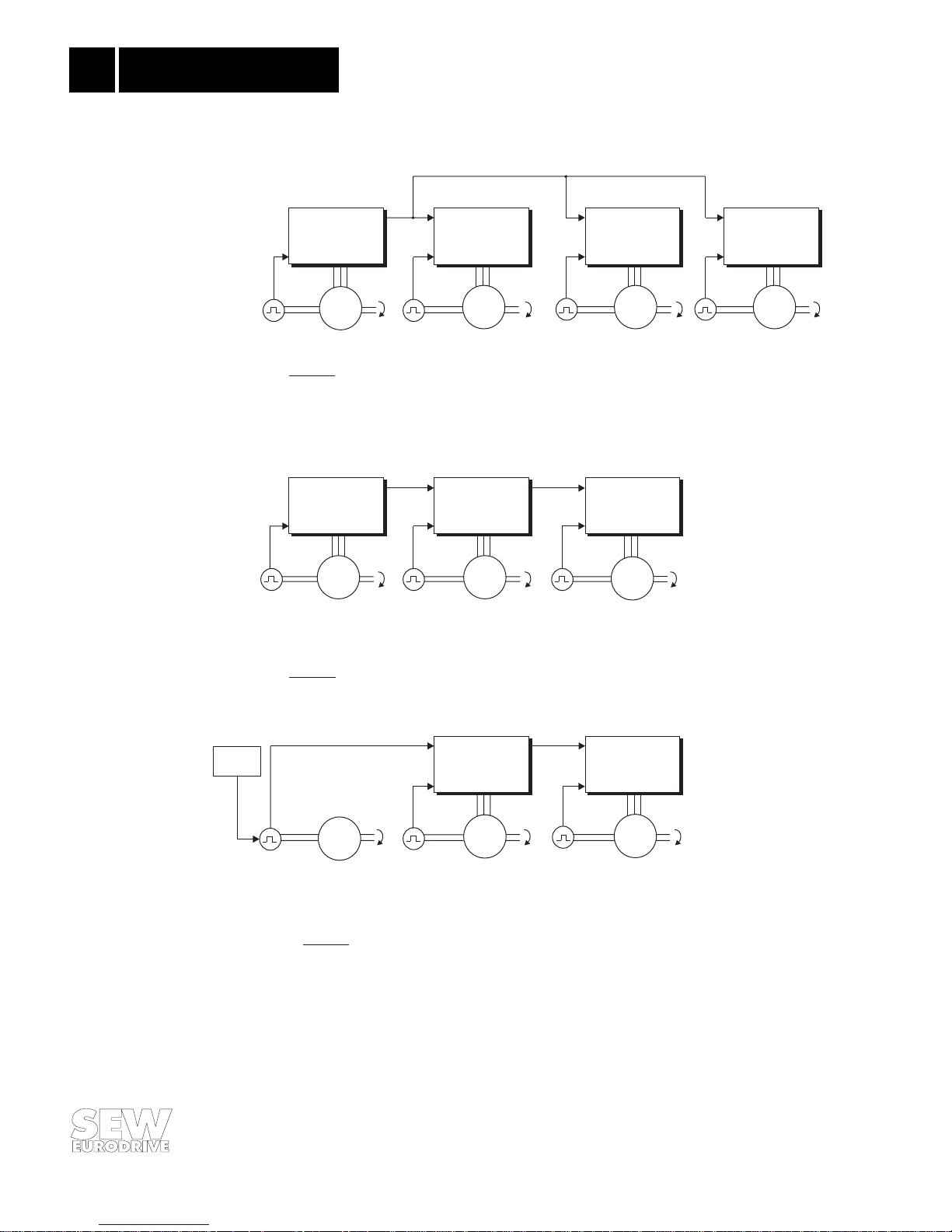
1.2 Application Examples
00588AEN
Fig. 1: Application Examples
X6
X5
MC 31.. +
FEN 31 / FPI 31
X6
X5
MC 31.. +
FEN 31 / FPI31
M1
n1
Master
Master 1
Master 2 Master 3
Slave 1
Slave 1 Slave 2
Slave 2 Slave 3
M2
n2
M3
n2
M4
n2
X6
X16
X17
X5
MC 31.. +
FRS 31
X6
X16
X17
X5
MC 31.. +
FRS 31
X6
X16
X17
X5
MC 31.. +
FRS 31
X6
X16
X17
X5
MC 31.. +
FRS 31
X6
X16
X17
X5
MC 31.. +
FRS 31
M1
n1
M2
n2
M3
n3
M1
n1
M2
n2
M3
n3
Master 1
Master 2
Slave 1
Master 3
Slave 2
X6
X16
X17
X5
MC 31.. +
FRS 31
X6
X16
X17
X5
MC 31.. +
FRS 31
Figure 3:
Master-slave chain,
power for encoder supplied by M 1 external.
Power supply
5VDC
Figure 2:
Master-slave chain
(e.g. calendar drives, bottle washing machines)
Figure 1:
Group configuration:
Master and several equal-priority slaves.
Up to 10 slaves (max.) connected to one master
(e.g. for multi-column hoists, travel drives for gantry cranes, belt drives).
Phone: 800.894.0412 - Fax: 888.723.4773 - Web: www.clrwtr.com - Email: info@clrwtr.com
 Loading...