

Page 1
Gearmotors \ Industrial Gear Units \ Drive Electronics \ Drive Automation \ Services
MOVI-PLC
Edition 07/2007
11617012 / EN
®
I/O System
M
anual
Page 2

SEW-EURODRIVE – Driving the world
Page 3

1 General Information ............................................................................................... 4
1.1 Structure of the safety notes .......................................................................... 4
1.2 Rights to claim under limited warranty ........................................................... 4
1.3 Exclusion of liability ........................................................................................ 4
1.4 Other applicable documentation .................................................................... 5
1.5 General safety notes for bus systems............................................................ 5
1.6 Safety functions ............................................................................................. 5
1.7 Hoist applications ........................................................................................... 5
2 System Description................................................................................................ 6
2.1 MOVI-PLC
®
I/O system ................................................................................. 6
2.2 Scope of delivery of the individual components ............................................. 7
2.3 Accessories.................................................................................................... 8
3 Installation .............................................................................................................. 9
3.1 Mechanical installation ................................................................................... 9
3.2 Electrical installation..................................................................................... 15
4 Unit Design and Technical Data of the MOVI-PLC
®
I/O System ...................... 18
4.1 CAN bus coupler OCC11B........................................................................... 18
4.2 OTM21B terminal module ............................................................................ 22
4.3 ODI81B digital input module ........................................................................ 24
4.4 ODO81B digital output module .................................................................... 27
4.5 OAI41B analog input module (voltage) ........................................................ 30
4.6 OAI42B analog input module (current)......................................................... 34
4.7 OAI43B analog input module (multi-input) ................................................... 38
4.8 OAO41B analog output module (voltage) .................................................... 49
4.9 OAO42B analog output module (current)..................................................... 54
4.10 OAO43B analog output module (multi-output)............................................. 58
5 Project Planning with MOVITOOLS
®
MotionStudio .......................................... 64
5.1 PLC Editor project planning tool................................................................... 64
5.2 Adding a MOVI-PLC
®
I/O system ................................................................ 64
5.3 Configuring I/O modules .............................................................................. 65
5.4 Configuring I/O modules .............................................................................. 66
5.5 IEC program................................................................................................. 66
6 Appendix............................................................................................................... 67
6.1 UWU52A switched-mode power supply....................................................... 67
7 Index...................................................................................................................... 68
Manual – MOVI-PLC® I/O System
3
Page 4
1
General Information
Structure of the safety notes
1 General Information
Manual
1.1 Structure of the safety notes
The safety notes in this manual are designed as follows:
Pictogram SIGNAL WORD!
Type and source of danger.
Possible consequence(s) if the safety notes are disregarded.
• Measure(s) to prevent the danger.
Pictogram Signal word Meaning Consequences in case of
disregard
Example:
General danger
DANGER! Imminent danger Severe or fatal injuries
WARNING! Possible dangerous situation Severe or fatal injuries
CAUTION! Possible dangerous situation Minor injuries
Specific danger,
e.g. electric shock
STOP! Possible damage to property Damage to the drive system or its environ-
NOTE Useful information or a tip
Simplifies the handling of the
drive system
1.2 Rights to claim under limited warranty
A requirement of fault-free operation and fulfillment of any rights to claim under limited
warranty is that you adhere to the information in the MOVI-PLC
fore, read the manual before you start operating the unit.
Make sure that the manual is available to persons responsible for the plant and its
operation, as well as to person who work independently on the unit. You must also
ensure that the documentation is legible.
ment
®
documentation. There-
1.3 Exclusion of liability
4
You must comply with the information contained in the MOVI-PLC® documentation to
ensure safe operation of the MOVI-PLC
®
controller and to achieve the specified product
characteristics and performance requirements. SEW-EURODRIVE assumes no liability
for injury to persons or damage to equipment or property resulting from non-observance
of these operating instructions. In such cases, any liability for defects is excluded.
Manual – MOVI-PLC® I/O System
Page 5

Other applicable documentation
1.4 Other applicable documentation
• Installation and startup only by trained personnel observing the relevant accident
prevention regulations and the following documents:
– "MOVIDRIVE
– "MOVITRAC
– "MOVIAXIS
–"MOVI-PLC
–"MOVI-PLC
– "Libraries for MOVI-PLC
– "MPLCUtilities Libraries for MOVI-PLC
–"MOVI-PLC
• Read through these documents carefully before you commence installation and
startup of the MOVI-PLC
®
MDX60B/61B" operating instructions
®
B" operating instructions
®
MX Multi-Axis Servo Inverter" operating instructions
®
basic DHP11B Controller" manual
®
advanced DH.41B" manual
®
programming in the PLC Editor" system manual
®
®
I/O system.
• As a prerequisite to fault-free operation and fulfillment of warranty claims, you must
adhere to the information in the documentation.
1.5 General safety notes for bus systems
You are now in possession of a communication system that lets you adapt MOVI-PLC
controllers, MOVI-PLC® I/O systems and the controlled inverters to your specific system. As with all bus systems, there is a danger of invisible, external (as far as the inverter
is concerned) modifications to the parameters which give rise to changes in the unit
behavior. This may result in unexpected (not uncontrolled) system behavior.
General Information
– Fault Codes" manual
®
" manual
1
®
1.6 Safety functions
MOVI-PLC® and the MOVI-PLC® I/O system may not perform safety functions.
For safety applications, refer to the information in the following publications.
• Safe disconnection for MOVIDRIVE
Use only those components in safety applications that were explicitly delivered in this
design by SEW-EURODRIVE!
1.7 Hoist applications
• Hoist applications can only be implemented with MOVI-PLC® under the following
conditions:
– A special hoist startup of the inverters must be performed.
• Do not use MOVI-PLC
conjunction with hoist applications.
Use monitoring systems or mechanical protection devices as safety equipment to
avoid possible damage to property or injury to people.
®
/ MOVIAXIS® / MOVITRAC® B
®
and the MOVI-PLC® I/O system for any safety functions in
Manual – MOVI-PLC® I/O System
5
Page 6
2
System Description
MOVI-PLC® I/O system
2 System Description
2.1 MOVI-PLC® I/O system
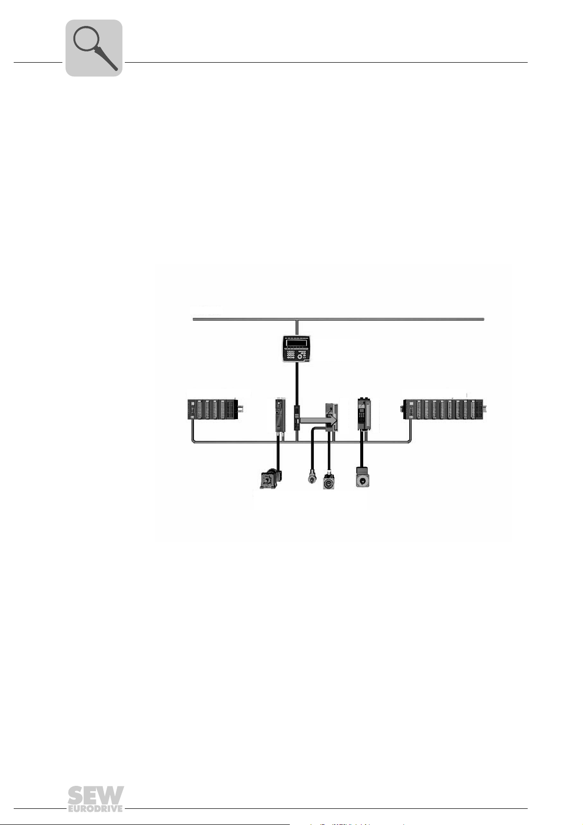
The modular MOVI-PLC® I/O system expands the digital and analog interfaces of the
MOVI-PLC
32 I/O modules can be connected via backplane bus. The bus coupler communicates
with the MOVI-PLC
PLC
PLC
•MOVI-PLC
• Inputs and outputs directly integrated in the MOVI-PLC
®
controller. A MOVI-PLC® I/O system contains a bus coupler to which up to
®
®
I/O systems can be connected to a MOVI-PLC® controller. This means the MOVI-
®
controller can automatically access a large number of inputs and outputs.
via system bus. Up to 126 bus couplers and consequently MOVI-
®
I/O systems
®
controller
• Inputs and outputs of the controlled inverters
ETHERNET
[1]
MOVI PLC® I/O System MOVI PLC® I/O System
®
®
MOVITRAC
MOVI PLC
MOVIDRIVE® MOVIDRIVE
®
[2] [3]
[1] Operator terminal (e.g. DOP11A)
[2] Asynchronous motor
[3] Servomotors
[4] System bus (connect MOVI-PLC
CAN1 and CAN2 of the MOVI-PLC
[4]
62069AXX
®
I/O systems and inverters separately to
®
controller)
6
Manual – MOVI-PLC® I/O System
Page 7
System Description
Scope of delivery of the individual components
2
Advantages of
the MOVI-PLC
I/O system
®
ule.
• Optimum integration into the programming software PLC Editor of the MOVITOOLS
• Powerful connection to the MOVI-PLC
®
controller via the SBus of the machine mod-
MotionStudio.
• A variety of combination options allows for implementing flexible and individual
machine solutions.
• The compact design and the modular structure reduce control cabinet space require-
ments to a minimum.
• Quick and easy installation or replacement in case of startup or service
2.2 Scope of delivery of the individual components
OCC11B bus coupler
ODI81B digital input module
Bus coupler backplane bus – CAN.
Typ e Part number
OCC11B 1821 479 7
I/O module with 8 binary inputs.
Typ e Part number
ODI81B 1821 481 9
®
ODO81B digital output module
OAI41B analog input module
OAI42B analog input module
OAI43B analog input module
OAO41B analog output module
I/O module with 8 binary outputs.
Typ e Part number
ODO81B 1821 482 7
I/O module (voltage) with 4 analog inputs.
Typ e Part number
OAI41B 1821 483 5
I/O module (current) with 4 analog inputs.
Typ e Part number
OAI42B 1821 484 3
I/O module (multi input) with 4 analog inputs.
Typ e Part number
OAI43B 1821 485 1
I/O module (voltage) with 4 analog outputs.
Typ e Part number
OAO41B 1821 487 8
OAO42B analog output module
Manual – MOVI-PLC® I/O System
I/O module (current) with 4 analog outputs.
Typ e Part number
OAO42B 1821 488 6
7
Page 8
2
System Description
Accessories
OAO43B analog output module
Terminal module OTM21B
2.3 Accessories
Connection cable OKC11B
Backplane bus connector OBP..B
I/O module (multi output) with 4 analog outputs.
Typ e Part number
OAO43B 1821 489 4
Terminal module for 2 or 3-wire installation
Typ e Part number
OTM21B 1821 490 8
Connection cable between MOVI-PLC® (X32 or X33 connection) and bus coupler
OCC11B.
Typ e Part number
OKC11B 1810 482 7
Each I/O module and each terminal module is supplied with a single-socket backplane
bus connector. 10 x single-socket backplane bus connectors are supplied for reorders.
Typ e Part number
OBP11B ( 10 × single backplane bus connector) 1821 491 6
OBP81B (1 × 8-socket backplane bus connector) 1821 492 4
UWU52A switched-mode power supply
NOTES
• When connecting I/O modules to one bus coupler, replace 8 single-socket backplane connectors by one 8-socket backplane connector OBP81 B each (i.e. 16 I/O
modules → 2 × 8-socket backplane bus connectors, etc.).
• The 8-socket backplane connectors OBP81B have to be ordered separately.
You can use the UWU52A switched-mode power supply for DC 24 V voltage supply of
the MOVI-PLC I/O system.
Typ e Part number
UWU52A 188 181 7
NOTES
• For installation notes and technical data of the UWU52A switched-mode power
supply unit, refer to the "Appendix" section.
• Observe the maximum rated output currents and the operating temperature.
8
Manual – MOVI-PLC® I/O System
Page 9
3 Installation
3.1 Mechanical installation
Notes on installing the modules of the MOVI-PLC® I/O system
STOP!
Observe the following points to prevent the I/O module from being damaged:
Switch off the voltage supply before you install or remove a module.
NOTES
• The individual modules are installed on a mounting rail. They are connected using
backplane bus connectors. The bus connector is placed into the profile rail that
carries the modules.
• The modules must always be installed directly next to each other. Gaps between
the modules are not permitted, else the backplane bus is interrupted.
• A row of modules is always installed from left to right and always begins with a bus
coupler.
• A module is not properly installed and electrically connected until it audibly locks in
place in the backplane connector.
• Plug-in locations to the right of the last module must not remain free.
Installation
Mechanical installation
3
Dimension drawing for mounting rail
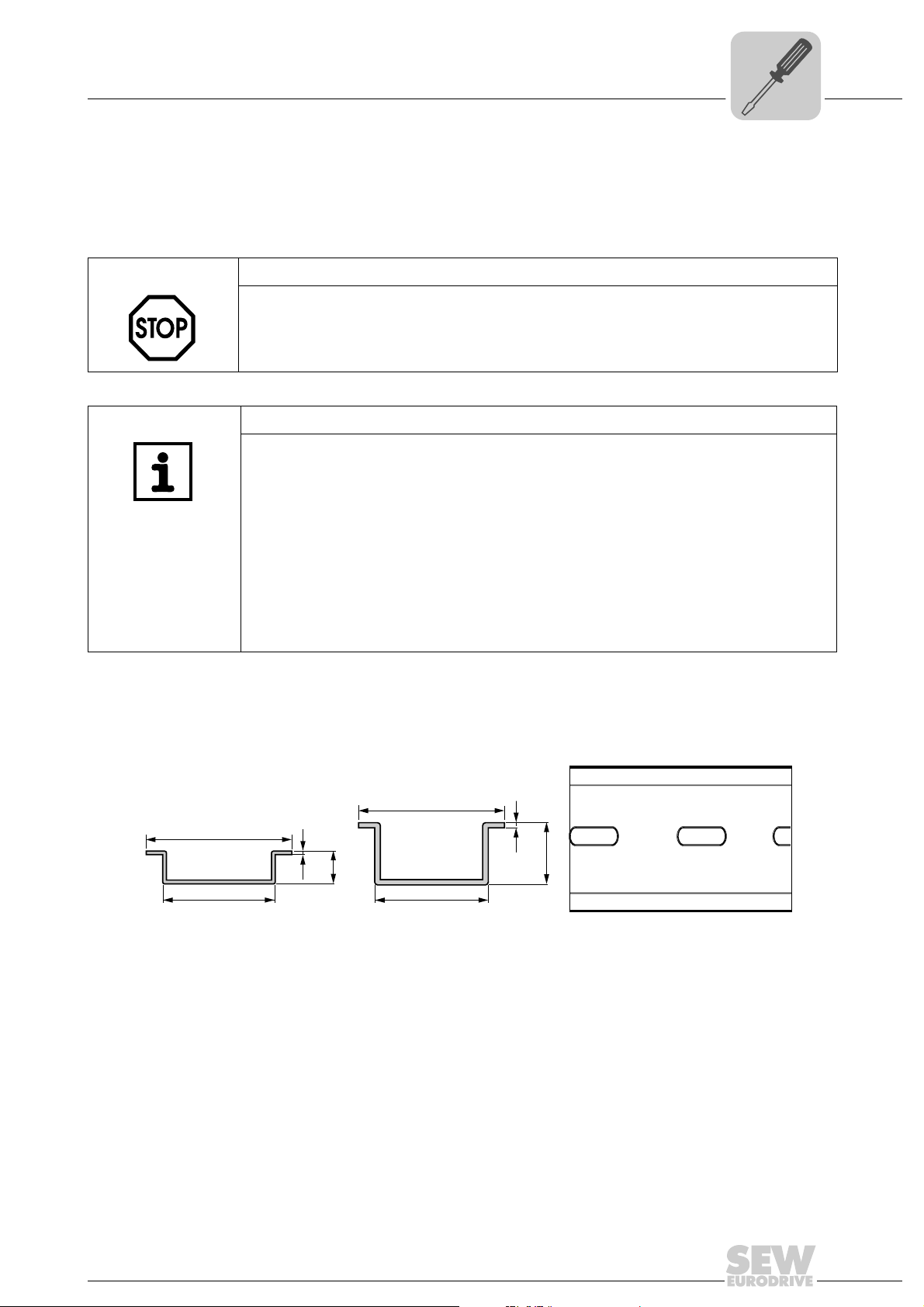
You can use the following 35 mm standard profile rail (→ following figure) for installation.
SEW-EURODRIVE recommends to use version II to ensure sufficient space for the
retaining screws under the backplane bus connector.
II
35
27
1.5
15
27
I
35
1
7.5
61989AXX
Manual – MOVI-PLC® I/O System
9
Page 10
3
Installation
Mechanical installation
Mounting position
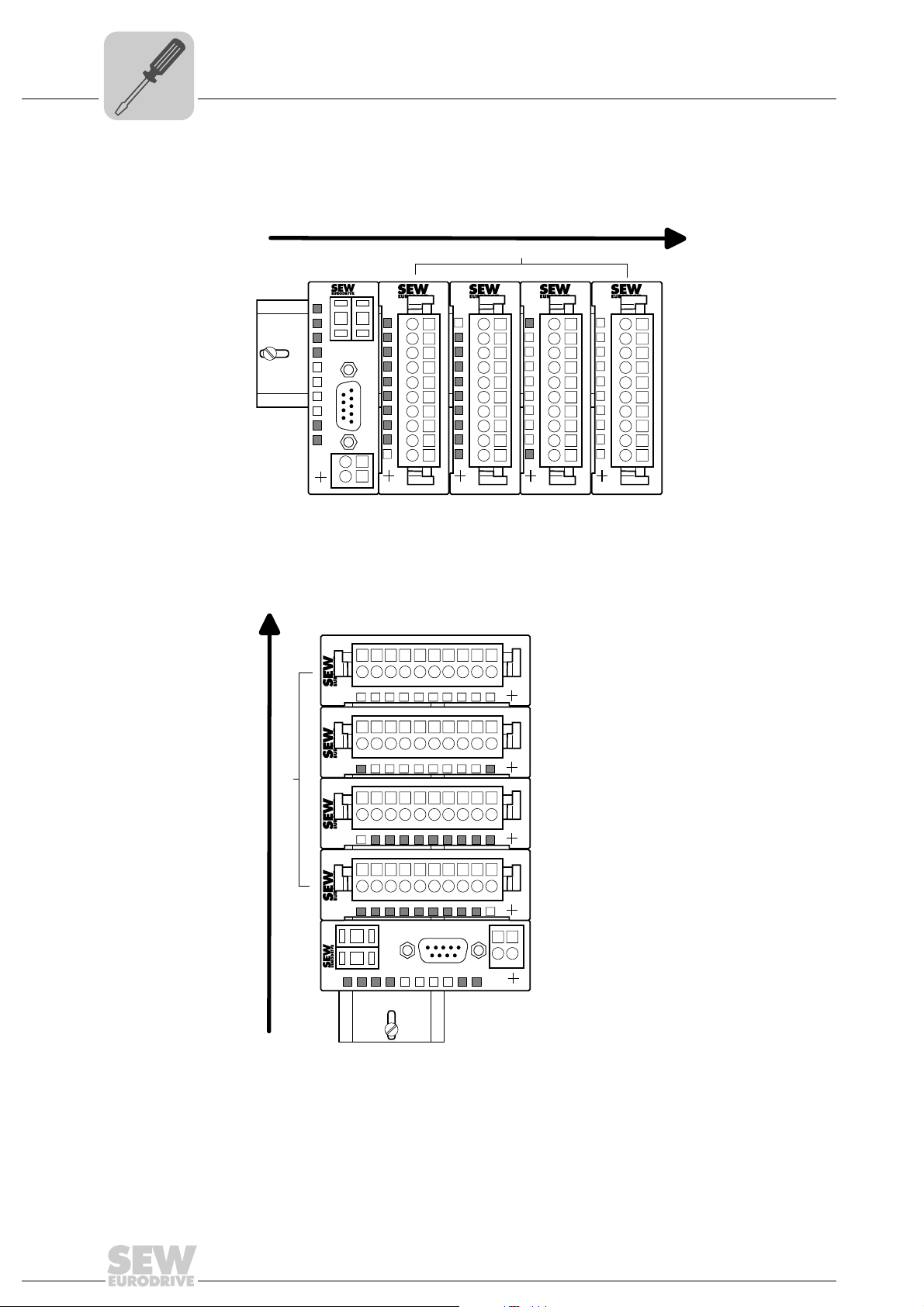
You can install a maximum of 32 I/O modules vertically or horizontally. You can also add
terminal modules. Observe the permitted ambient temperatures:
• Horizontal installation: Ambient temperature of 0 °C to 60 °C
1
2
3
4
5
6
7
8
9
10
OAO41B
[2]
L+
1
2
3
4
5
6
7
8
9
10
ODI81B
DI8xDC24V
1
2
3
4
5
6
7
8
9
10
0
1
2
3
4
5
6
7
F
X3
45
DI8xDC24V 0,5A
1
0
2
1
3
2
4
3
5
4
6
5
7
6
8
7
9
10
X3
45
1
2
3
4
5
6
7
8
9
10
1
2
3
4
5
6
7
8
9
10
ODO81B
62004AXX
24V
DC
X3
45
[1]
7 5
ADR
PW
ER
RD
BA
1
2
3
4
5
C
6
A
7
N
8
9
X1
SF
+
10
X2
34
OAI41B
AI 4x12Bit Volt AO 4x12Bit Volt
L+
1
2
3
4
5
6
7
8
9
10
X3
45
[1] Bus coupler [2] I/O modules
• Vertical installation: Ambient temperature of 0 °C to 40 °C
[2]
[1]
123456789
123456789
1234567
0
L+
123456789
123456789
0123456
123456789
123456789
L+
123456789
123456789
CAN
7 5
ADR
ER
RD
PW
10
ODO81B
10
DI8xDC24V 0,5A
F
X3
45
10
ODI81B
DI8xDC24V
10
7
X3
45
10
OAO41B
10
X3
45
10
OAI41B
10
AI 4x12Bit Volt AO 4x12Bit Volt
SF
X2
34
X1
BA
+
X3
45
DC
24V
[1] Bus coupler [2] I/O modules
62005AXX
10
Manual – MOVI-PLC® I/O System
Page 11
Installation
Mechanical installation
3
Installation clearance
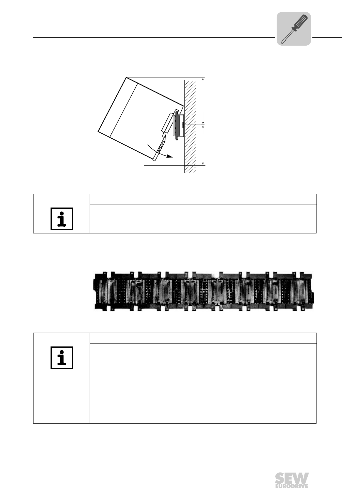
Ensure a minimum clearance of 80 mm above and 60 mm below the middle of the backplane connector when installing the components.
80mm
60mm
62006AXX
NOTE
The switched-mode power supply used may require other installation distances.
Please observe the technical data of the switched-mode power supply in use.
Backplane bus connector
Insert single-socket or 8-socket backplane bus connectors (→ following figure) into the
mounting rail for communication of the I/O modules and terminal modules. The individual plug-in locations for the module are defined by guide rails.
62086AXX
NOTES
• Each I/O module and each terminal module is supplied with a single-socket backplane bus connector. When connecting I/O modules and terminal modules to one
bus coupler, replace 8 single-socket backplane connectors by one 8-socket backplane bus connector OBP81B.
Example: For 20 I/O modules, use two 8-socket backplane bus connectors and four
single-socket backplane bus connectors.
• Also refer to the notes in the sections "Step-by-step installation of the MOVI-PLC
I/O system" and "Configuration of I/O modules".
• The switched-mode power supply is not plugged into the backplane bus connector
but is installed next to the MOVI-PLC
®
I/O system.
®
Manual – MOVI-PLC® I/O System
11
Page 12
3
Installation
Mechanical installation
Installation on
mounting rail
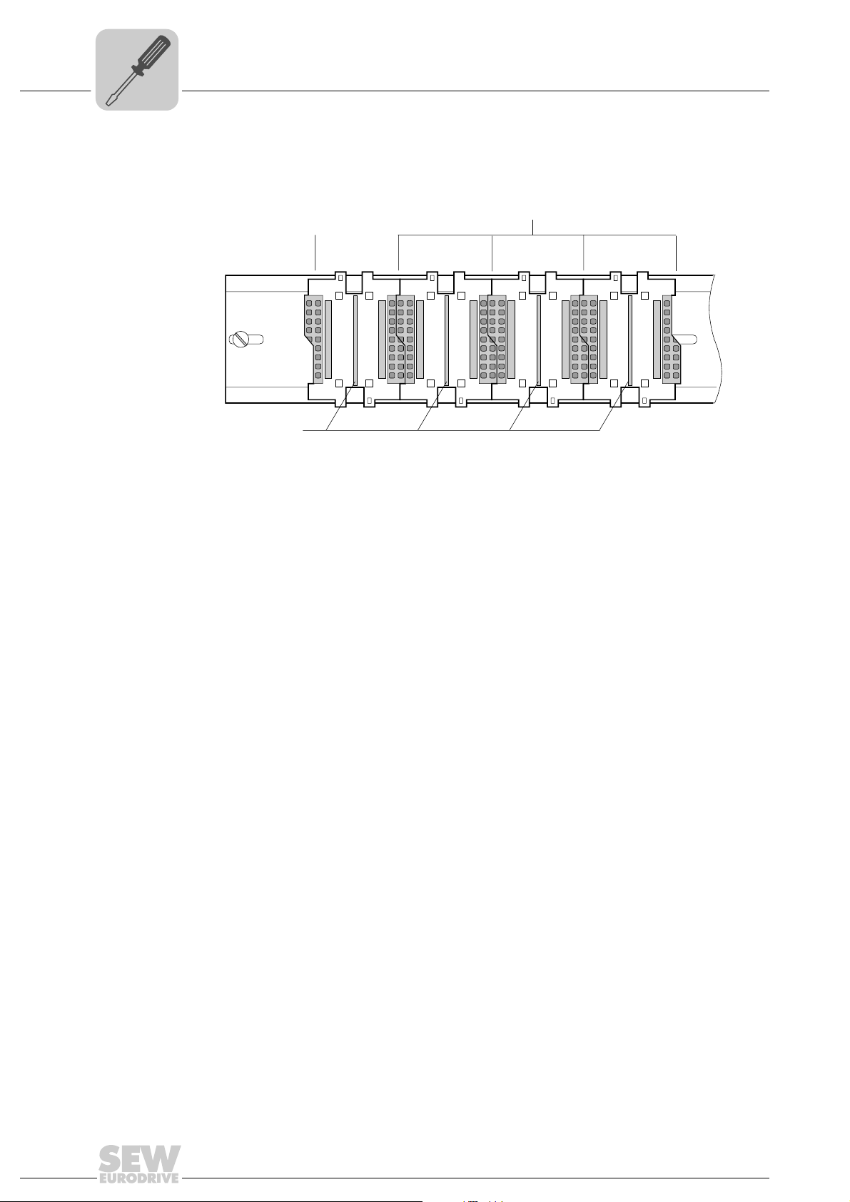
Press the backplane bus connector into the mounting rail until it audibly locks in place.
The following figure depicts four single-socket backplane connectors used as module
slots.
[2]
[1]
[3]
62007AXX
[1] Bus coupler slot
[2] I/O and terminal plug-in locations
[3] Guide rails
12
Manual – MOVI-PLC® I/O System
Page 13
Step-by-step installation of the MOVI-PLC® I/O system
Proceed as follows to install the keypad:
STOP!
Observe the following points to prevent the I/O module from being damaged:
Switch off the power supply before you insert or remove any modules.
NOTES
• If you operate various modules in a MOVI-PLC® I/O system, follow the specified
installation sequence of the modules from perspective of the bus coupler:
– First plug in the analog input modules directly next to the bus coupler
– Then plug in the analog output modules next to the analog input modules
– Finally plug in the digital modules
• Arrange the terminal modules as far to the right as possible. You can also plug
individual terminal modules at any location between the I/O modules.
• You can operate up to 32 I/O modules in a MOVI-PLC
coupler). If you do not use an analog input module, you can plug a total of 32 analog
output modules and digital modules in any combination without checking. Terminal
modules can be plugged additionally.
• When using analog input modules, it is important that the total current consumption
of all modules via the backplane bus does not exceed the output current of the bus
coupler backplane bus. Observe the information in the "Unit design and technical
data MOVI-PLC
• Observe the notes in the "Backplane bus connector" and "Configuration of I/O
modules" sections.
®
I/O system" section.
Installation
Mechanical installation
®
I/O system (i.e. at one bus
3
1. Install the mounting rail. Ensure the minimum clearance of at least 80 mm above and
60 to below the middle of the profile rail.
2. Insert the backplane bus connector into the profile rail until it audibly locks in place.
The bus connections protrude from the rail.
3. Start with the bus coupler at the left and plug in the required I/O modules and terminal
modules to the right of the bus coupler.
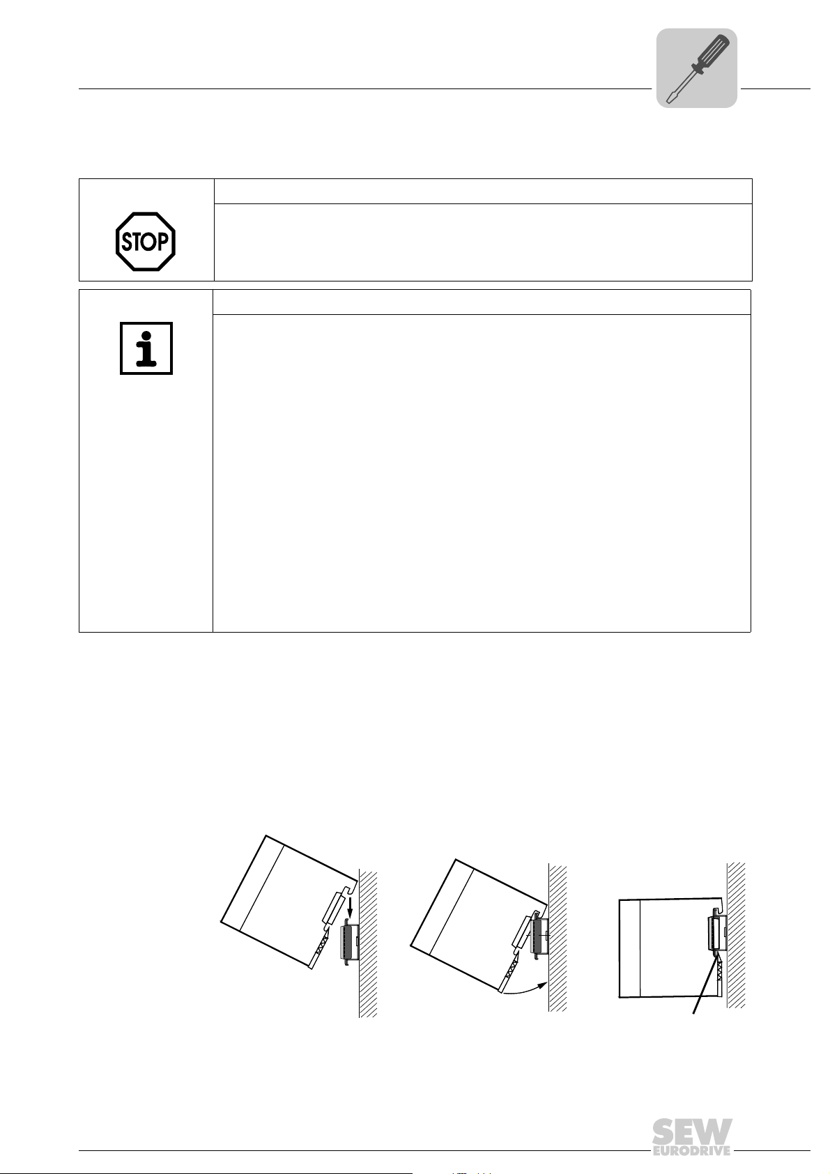
4. Place the module you want to install from top at an angle of approx. 45 degrees onto
the mounting rail and move the module downwards until it audibly locks in place on
the mounting rail (→ following figure). Only then will the module be properly
connected with the backplane bus.
CLACK
62026AXX
Manual – MOVI-PLC® I/O System
13
Page 14
3
Step-by-step removal of the MOVI-PLC® I/O system
Installation
Mechanical installation
Proceed as follows for removing modules:
STOP!
Observe the following points to prevent the I/O module from being damaged:
Switch off the power supply before you insert or remove a module.
NOTE
The backplane bus is interrupted at the point where the module was removed.
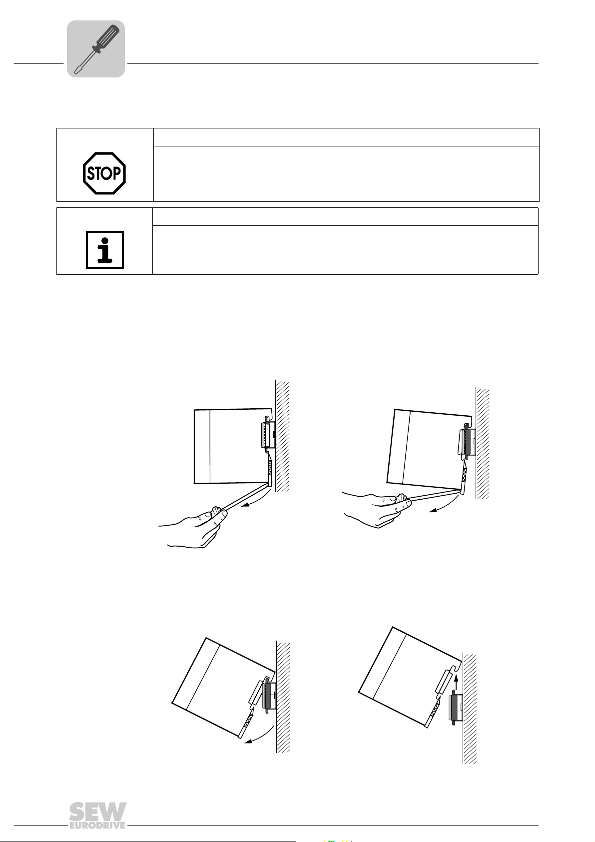
1. The enclosure of the module has a spring-loaded clip at the bottom by which the
module can be removed from the rail.
2. Insert a suitable screwdriver into the slot. The module is unlocked by pressing the
screwdriver in an upward direction (→ following figure, pos. I).
3. Remove the module toward you slightly turning it to the top (→ following figure, pos.
II).
I
II
14
62027AXX
Manual – MOVI-PLC® I/O System
Page 15

3.2 Electrical installation
Installation
Electrical installation
3
EMC-compliant installation
• When installing the modules, ensure that any inactive metal components are
grounded via a proper large-surface earth.
– Provide a wide area metal-on-metal contact between the unit housing and
ground.
– Establish a central connection between ground and the earthing/PE system.
– If possible, do not use any aluminum components.
• Ensure that wiring is routed properly during installation.
– Route power cables (power current, power supply) and signal cables in separate
cable ducts.
– Route signal cables as close as possible to ground surfaces (e.g. frames, metal
rails, sheet metal, etc.).
• Ensure that the shielding of lines is grounded properly.
– Signal lines must be shielded.
– Signal lines with analog signals must be shielded. If low-amplitude signals are
transferred, it may be advantageous to connect the shield on one side of the cable
only.
– Attach the shields of cables in the control cabinet over a large surface area to the
ground rail/PE rail. Secure the line shields using cable clamps.
– Ensure that the ground rail/PE rail has a low-impedance connection to the control
cabinet.
– Use metallic or metallized plug connector housings for shielded signal lines.
• Use incandescent lamps for illumination inside control cabinets. Do not use fluorescent lamps.
• Create a single reference potential and ground all electrical equipment wherever
possible.
– Ensure that earthing measures are implemented effectively.
– Provide a star-shaped connection between system components and control
cabinets of the MOVI-PLC
way, you avoid ground loops.
– Where potential differences exist, you must install sufficiently large equipotential
bonding conductors between the different parts of the system and control
cabinets.
®
I/O system and the earthing/protection system. In this
Shielding of lines Observe the following points when shielding lines:
• Only use lines with braided shield.
The coverage of the shield should exceed 80 %.
• Always ground the line shields at both ends of cables. High frequency interference
can only be suppressed by grounding cables on both ends.
• Always use metallic or metallized connectors for signal lines for serial links. Connect
the shield of the signal line to the connector housing. Do not connect the shield to pin
1 of the plug strip of the I/O module.
• For stationary operation, we recommend that you strip the insulation from the shielded cable interruption-free and attach the shield to the shield/protective ground rail.
• Connect braided shields by means of metallic cable clamps. The cable glands must
have a good electrical and large surface contact with the shield.
Manual – MOVI-PLC® I/O System
15
Page 16
3
Installation
Electrical installation
• Attach the shield of a cable to the grounding rail directly where the cable enters the
control cabinet. Continue to route the shield right up to the I/O system but do not
connect the shield to ground at this point.
NOTES
• Where potential differences exist between earthing connection, it is possible to
establish a compensating current flow where the shield of a cable is connected at
both ends.
• Make sure you supply adequate equipotential bonding according in accordance
with relevant VDE regulations in such a case.
Wiring plug connectors
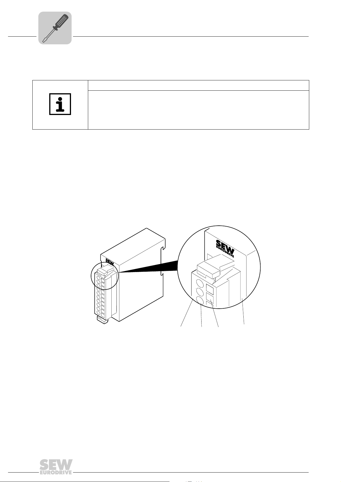
The I/O terminal modules are equipped with a 10-pole connector. This connector
provides the electrical interface for the signal and supply lines of the modules.
You can connect cables with a cross section of 0.08 mm
2
to 2.5 mm2 to the modules.
Connectors with spring-clip technique are used for wiring purposes. The spring-clip
technique simplifies the wiring of signal and voltage supply cables.
Unlike screw terminal connections, spring-clip wiring is vibration proof. The connector
assignment of the individual modules is explained in the sections on the respective
modules.
The following figure shows an I/O module with a 10-pole connector.
.0
.1
1
2
3
4
5
6
7
8
9
10
1
.2
2
.3
3
.4
4
.5
5
.6
6
.7
7
8
9
I0
1
2
3
.0
.1
.2
.3
1
2
3
.4
16
[2][1] [3] [1]
62066AXX
[1] Pin no.
[2] Round opening for wires
[3] Rectangular opening for screw driver
Manual – MOVI-PLC® I/O System
Page 17
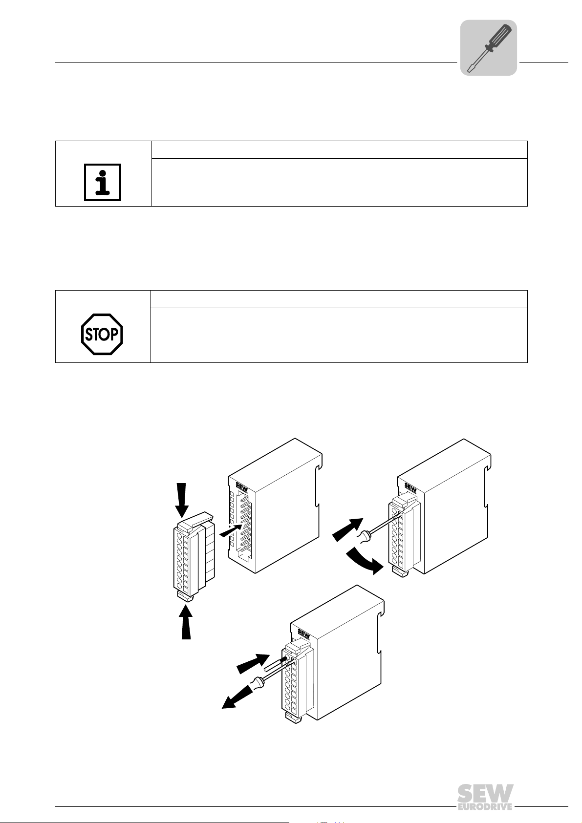
Procedure for wiring the plug connectors
Proceed in the following sequence:
NOTE
First connect the voltage supply lines, next the signal lines.
• To install the connector, press the two clips together. Now plug the connector onto
the module (→ following figure, step 1). The connector is properly installed when it
audibly locks in place.
• Insert a suitable screw driver at an angle into the rectangular opening of the plug
connector contact (→ following figure, step 2). Press and hold the screw driver in the
opposite direction to open the contact spring (→ following figure, step 3).
STOP!
The spring-clip is destroyed if you insert the screw driver into the round opening for the
wires.
Make sure that you only insert the screw driver into the rectangular opening of the
connector.
Installation
Electrical installation
3
• Insert the stripped end of the wire into the round opening. You can use wires with a
cross section of 0.08 mm
2
to 2.5 mm2 to the I/O terminal modules (→ following
figure, step 4).
• Remove the screw driver from the rectangular opening (→ following figure, step 5).
The wire is now clipped securely to the connector.
1.
1
2
3
4
5
6
7
8
9
10
.0
.1
1
.2
2
.3
3
.4
4
.5
5
.6
6
.7
7
8
9
I0
2.
3.
.0
.1
1
2
3
4
5
6
7
8
9
10
1
.2
2
.3
3
.4
4
.5
5
.6
6
.7
7
8
9
I0
1.
.0
.1
4.
5.
1
2
3
4
5
6
7
8
9
10
1
.2
2
.3
3
.4
4
.5
5
.6
6
.7
7
8
9
I0
Manual – MOVI-PLC® I/O System
62041AXX
17
Page 18
4
Unit Design and Technical Data of the MOVI-PLC® I/O System
CAN bus coupler OCC11B
4 Unit Design and Technical Data of the MOVI-PLC® I/O System
4.1 CAN bus coupler OCC11B
Part number 1821 479 7
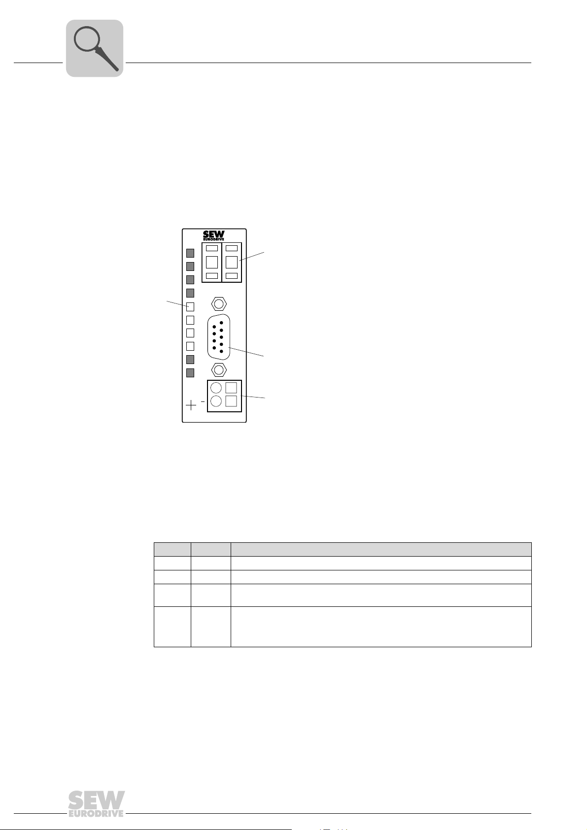
Description The CAN bus coupler OCC11B (→ following figure) connects the MOVI-PLC
system with the MOVI-PLC
®
controller via the system bus from SEW-EURODRIVE. It
supports all CAN transmission rates.
[2]
7 5
ADR
[1]
DC
24V
X3
45
PW
ER
RD
BA
+
OCC11B
X1
C
A
N
[3]
1
[4]
2
62073AXX
[1] LED status indicators
[2] Address adjuster for setting baud rate and module ID
[3] CAN bus plug connector
[4] Port for external DC 24 V supply voltage
®
I/O
Diagnostics LED The CAN bus coupler OCC11B comes equipped with 4 diagnostics LEDs.
LED Color LED status / meaning
PW Green Lights up if operating voltage is present.
ER Red Lights up if error occurs during backplane bus transfer
RD Green • Flashes with 1 Hz if self-test was positive and initialization successful
BA Yellow • Off if self-test was positive and initialization successful
18
• Lights during data transmission via SBus
• Flashes with 1 Hz in "pre-operational" status
• Lights up in "operational" status
• Flashes with 10 Hz in "prepared" status
Manual – MOVI-PLC® I/O System
Page 19

Unit Design and Technical Data of the MOVI-PLC® I/O System
®
CAN bus coupler OCC11B
Combinations A combination of diagnostics LEDs indicates various states.
LED status Meaning
PW on
CAN plug connector assignment
ER on
RD on
BA on
PW on
ER flashes with 1Hz
RD flashes with 1 Hz
BA flashes with 1 Hz
PW on
ER flashes with 10Hz
RD flashes with
10 Hz
BA flashes with 10Hz
PW on
ER off
RD flashes with 1 Hz
BA off
The CAN bus coupler OCC11B is connected to the MOVI-PLC
terminal) using a 9-pin plug connector ("CAN" socket).
9-pin plug connector "CAN" PIN Assignment
Error during RAM or EEPROM initialization.
Baud rate setting activated.
Incorrect CAN baud rate setting.
(no ACK from the bus master)
Module ID setting activated.
1 Not assigned
1
6
2
7
3
8
4
9
5
62076AXX
2CAN low
3 CAN ground
4 Not assigned
5 Not assigned
6 Not assigned
7 CAN high
8 Not assigned
9 Not assigned
®
controller (X32 or X33
4
CAN bus cabling • For connecting the OCC11B bus coupler to the MOVI-PLC
terminal), use the prefabricated cable of SEW-EURODRIVE (length: 1.5 m) with integrated terminating resistors.
– Part number of the prefabricated cable: 1810 482 7
OCC11B
CAN
1
6
7
8
9
• You can connect more MOVI-PLC
MOVI-PLC
7
2
3
4
5
120
2
3
®
controller. To do so, remove the 120 Ω terminating resistor.
YE
GN
BR
WH
1500 mm
120
®
I/O systems to the X32/X33 connector of the
®
controller (X32 or X33
MOVI-PLC
X32/X33
123
2
3
1
123
62082AXX
Manual – MOVI-PLC® I/O System
19
Page 20
4
Unit Design and Technical Data of the MOVI-PLC® I/O System
CAN bus coupler OCC11B
NOTES
• CAN bus uses a shielded three-wire line as transmission medium.
• In systems with more than two stations, all stations are wired in parallel. The bus
cable must be looped without interruption for this purpose.
• The bus cable must always be connected with a terminating resistor of 120 Ω on
the line ends to avoid reflections and consequently transmission problems.
Voltage supply The CAN bus coupler OCC11B comes equipped with an integrated power supply unit.
The power supply unit must be supplied with DC 24 V. The supply voltage supplies the
bus coupler electronics and the connected I/O modules via the backplane bus. The power supply unit is protected against damage in the event of reverse polarity or overcurrent.
CAN bus and backplane bus are electrically isolated from each other.
NOTE
Correct polarity of the voltage supply at the X1 plug connector is required to avoid
failure of the bus coupler.
Setting the baud rate using the address adjuster
Use the address adjuster to set the CAN baud rate and the module ID.
• Set address 00 on the address adjuster.
• Activate the voltage supply for the CAN bus coupler.
The diagnostic LEDs "ER", "RD" and "BA" flash with 1 Hz. Now you have 5 seconds
time to programm the CAN baud rate using the address adjuster.
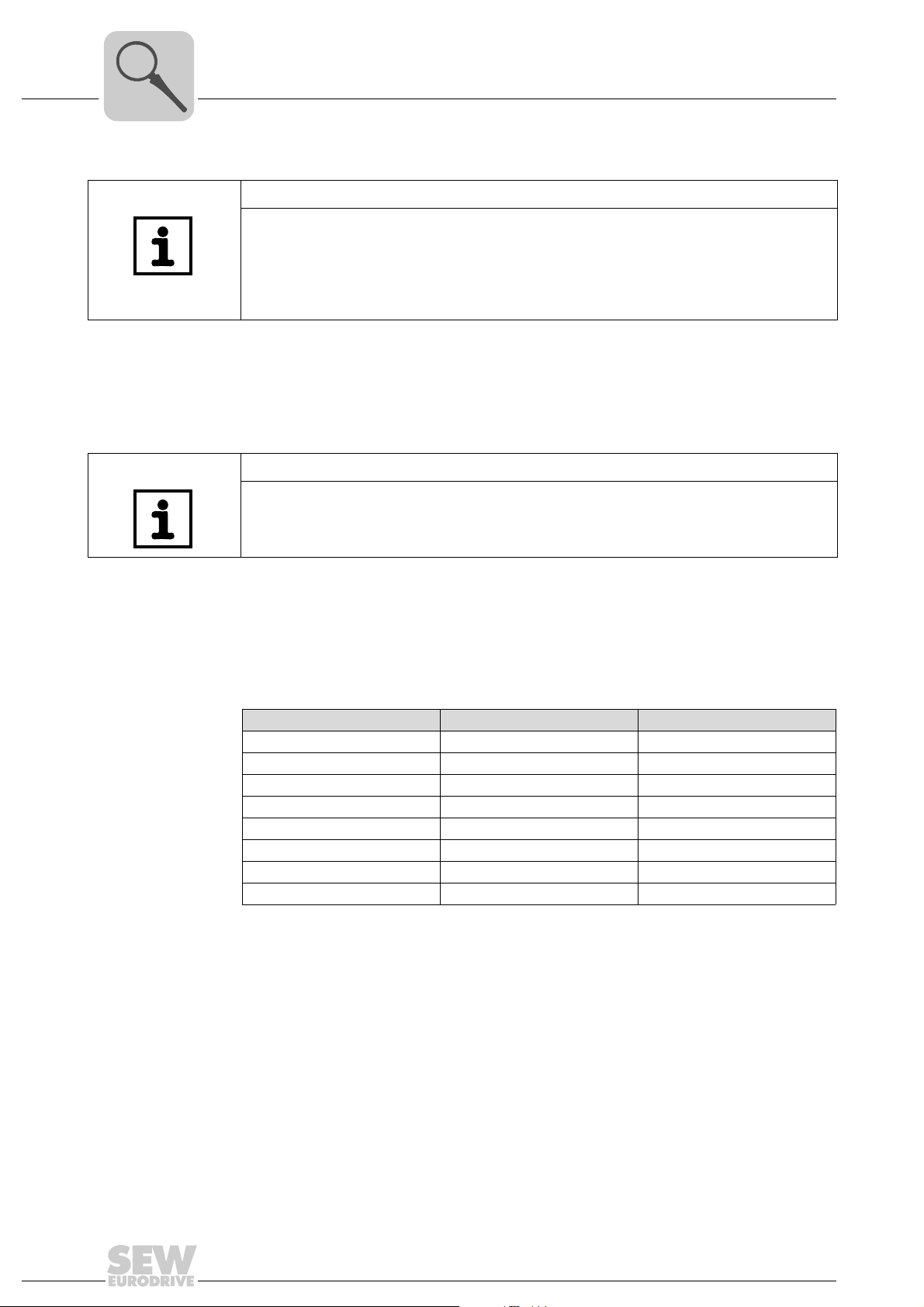
Address adjuster CAN baud rate Maximum bus length
00 1 MBaud 25 m
01 500 kBaud (factory setting) 100 m
02 250 kbaud 250 m
03 125 kbaud 500 m
04 100 kbaud 600 m
05 50 kbaud 1000 m
07 20 kbaud 2500 m
08 800 kbaud 50 m
The CAN baud rate will be saved after 5 seconds.
20
Manual – MOVI-PLC® I/O System
Page 21
Unit Design and Technical Data of the MOVI-PLC® I/O System
Setting the module ID
Technical data
CAN bus coupler OCC11B
NOTE
• The module ID must be set when you have set the baud rate and before switching
on the bus coupler again.
• Each module ID must only be assigned to the CAN bus once. Do not connect any
inverters to the CAN bus.
• The "ER" and "BA" diagnostics LEDs go out and the green "RD" LED continues to
flash.
• Use the address adjuster to set the module ID in the range from 1 to 63.
• The settings will be accepted after 5 seconds and the bus coupler enters normal
operation ("pre-operational" status).
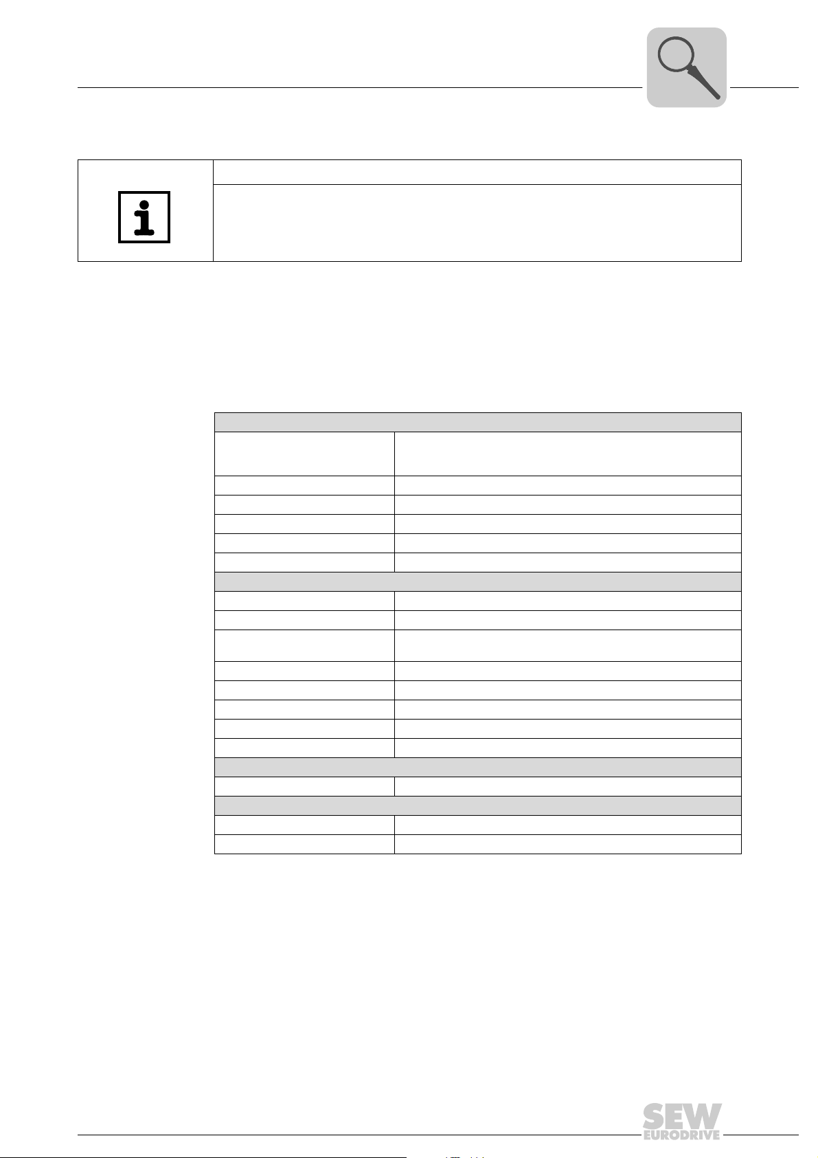
Electrical data of OCC11B
Voltage supply X1
Current consumption Max. DC 0.7 A
Output current backplane bus Max. DC 3.5 A
Galvanic isolation AC 500 V
Status display LEDs on the front panel
Connections/interfaces CAN bus: 9-pin sub-D connector
CAN bus interface
Coupling 9-pin sub-D connector
Network topology Linear bus, active bus termination at one end, spur lines are possible
Medium
Transmission rate 10 kBaud ... 1 MBaud (factory setting: 500 kBaud)
Maximum total length Without repeater: 1000 M at 50 kBaud
Binary inputs / outputs Max. 32 I/O modules can be combined per bus coupler
Maximum number of stations 63 stations
Address setting 1 ... 63 (factory setting: 1)
Combination with I/O modules
Maximum number of modules 32
Dimensions and weight
Dimensions (W ×H ×D) in mm 25.4 ×76 ×78
Weight 80 g
X1:1
X1:2
DC+24 V input (20.4 V ... 28.8 V)
Reference 24 V
Shielded, three-wire cable. Depending on the ambient conditions,
shielding is not necessary.
4
Manual – MOVI-PLC® I/O System
21
Page 22
4
Unit Design and Technical Data of the MOVI-PLC® I/O System
OTM21B terminal module
4.2 OTM21B terminal module
Part number 1821 490 8
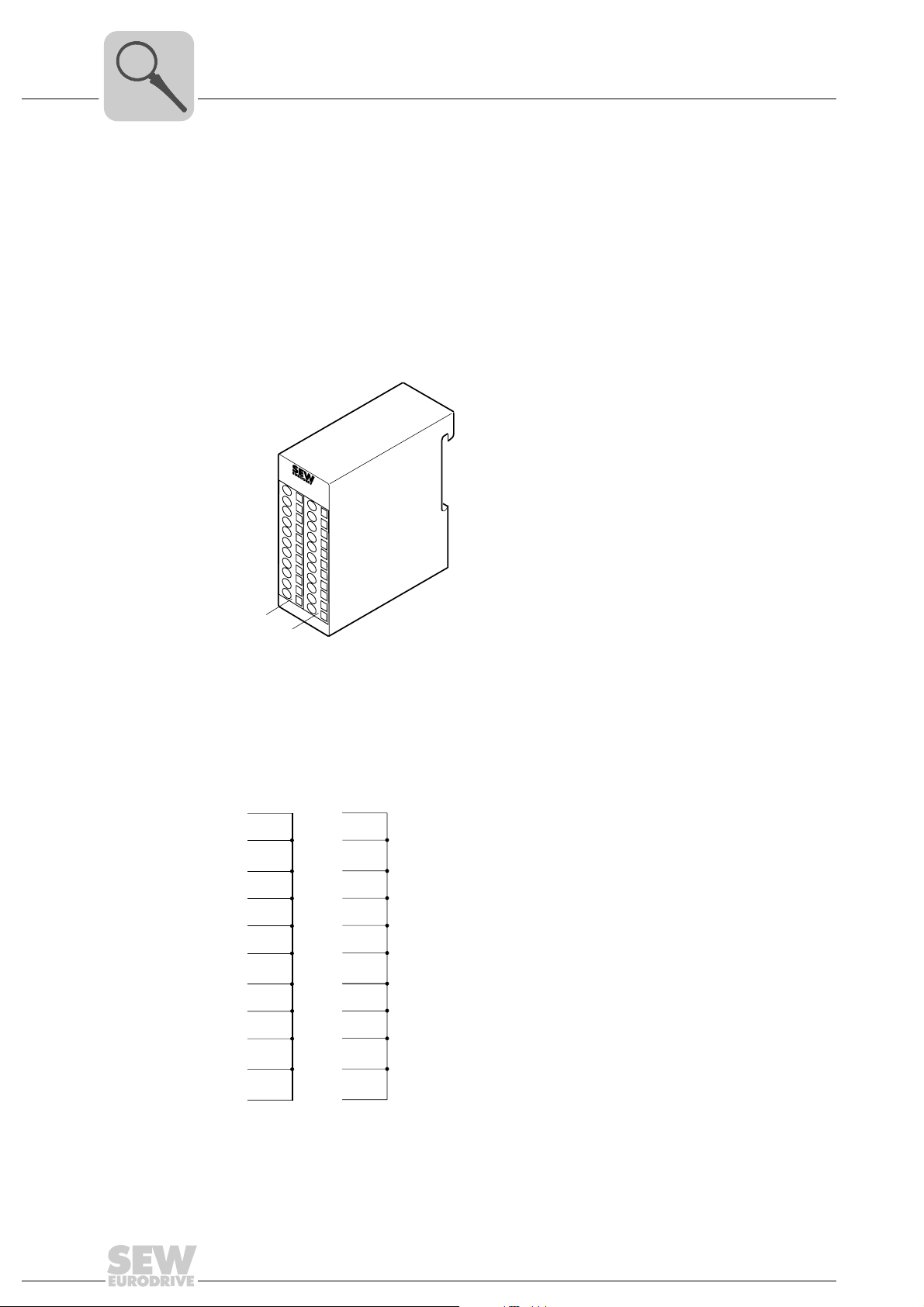
Description The OTM21B terminal module is a complementary module for 2-wire or 3-wire installa-
tion. The module is not connected to the backplane bus.
• 2 separate rows with 11 electrically interconnected terminals.
• No connection to the backplane bus
• Maximum terminal current DC 10 A
X1
X2
Wiring diagram
[1]
[2]
[1] First terminal strip
[2] Second terminal strip
1
2
3
4
5
6
7
8
9
10
X1
1
2
3
4
5
6
7
8
9
10
X2
62077AXX
22
11
11
62078AXX
Manual – MOVI-PLC® I/O System
Page 23

Unit Design and Technical Data of the MOVI-PLC® I/O System
Technical data
OTM21B terminal module
Electrical data of OTM12B
Number of rows 2
Number of terminals per row 11
Maximum terminal current DC 10 A
Terminal color Gray
Dimensions and weight
Dimensions (W ×H ×D) [mm] 25.4 × 76 × 88
Weight 50 g
4
Manual – MOVI-PLC® I/O System
23
Page 24
4
Unit Design and Technical Data of the MOVI-PLC® I/O System
ODI81B digital input module
4.3 ODI81B digital input module
Part number 1821 481 9
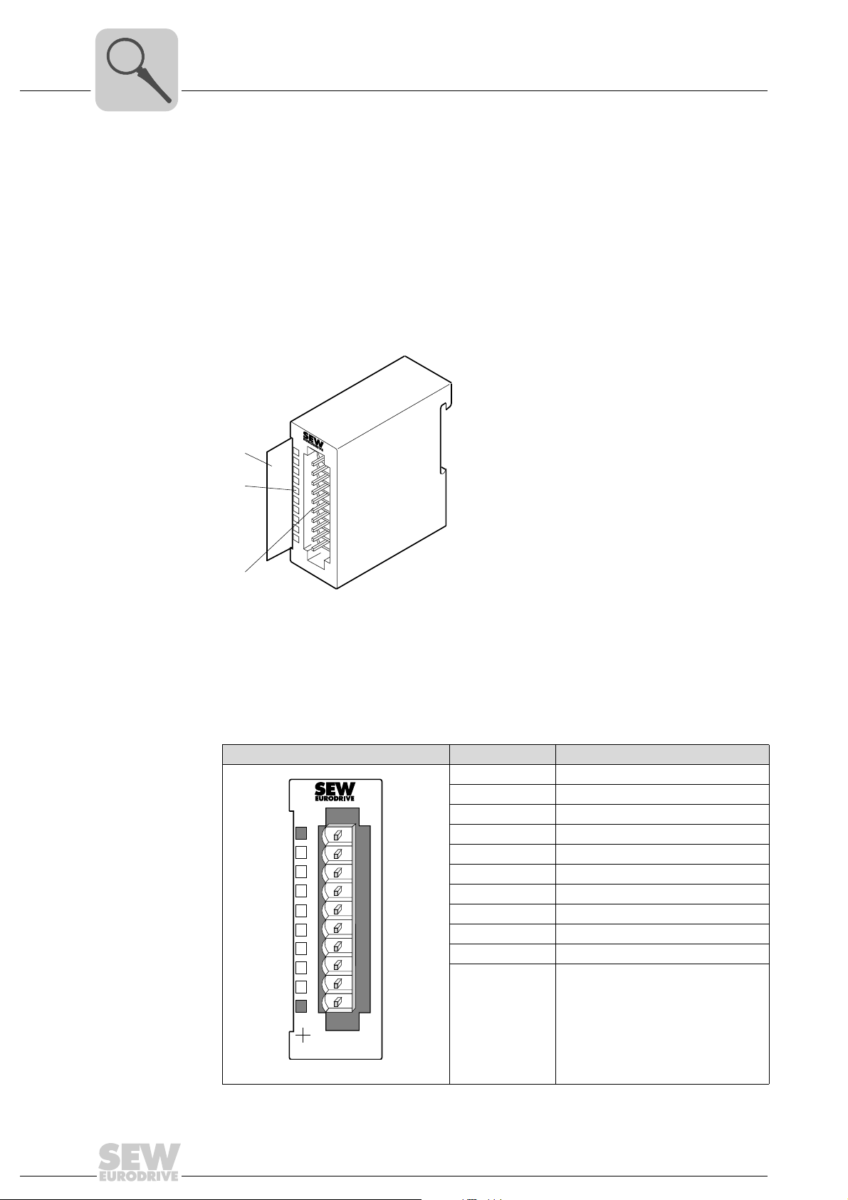
Description The ODI81B digital input module has 8 binary inputs, each one with an LED to indicate
the status.
• 8 binary inputs, galvanically isolated from the backplane bus
• DC 24 V rated input voltage
• LED status indicator for binary inputs
[1]
1
[2]
[3]
2
3
4
5
6
7
8
9
I0
Connector assignment
[1] Label for the bit address with description
[2] LED status indicator for binary inputs
[3] Connector strip
ODI81B Terminal/LED Assignment/description
1 Not assigned
2 Binary input 0
3 Binary input 1
4 Binary input 2
5 Binary input 3
6 Binary input 4
7 Binary input 5
8 Binary input 6
9 Binary input 7
10 Weight
LED 0 ... 7 Status indicator for binary inputs 0 ... 7
X3
45
0
1
2
3
4
5
6
7
ODI81B
DI 8xDC24V
1
2
3
4
5
6
7
8
9
10
62050AXX
62259AXX
24
Manual – MOVI-PLC® I/O System
Page 25
Unit Design and Technical Data of the MOVI-PLC® I/O System
ODI81B digital input module
4
LED status indicator
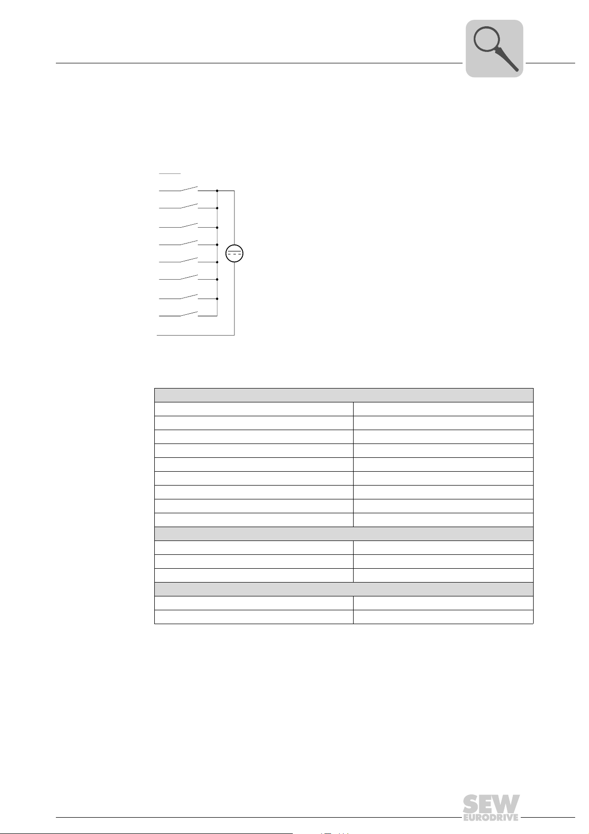
Wiring diagram
Technical data
LEDs 0 ... 7 light up green if signal "1" is detected from approx. DC 15 V onwards.
1
2
3
4
5
6
7
8
9
10
M
DC 24V
62061AXX
Electrical data of ODI81B
Number of binary inputs 8
Rated input voltage DC 24 V (20.4 ... 28.8 V)
Signal voltage "0" 0 ... 5 V
Signal voltage "1" 15 ... 28.8 V
Input filter time delay 3 ms
Input current typ. 7 mA
Current consumption from backplane bus DC 25 mA
Galvanic isolation 500 V
Status indicator via LEDs located on the front
Programming data
Input data 1 byte
Output data Diagnostic data -
Dimensions and weight
Dimensions (W ×H ×D) [mm] 25.4 × 76 × 88
Weight 50 g
(field voltage to the bus)
rms
Manual – MOVI-PLC® I/O System
25
Page 26
4
Parameter setting Make the following settings in the module parameters (→ section "Parameter setting of
Unit Design and Technical Data of the MOVI-PLC® I/O System
ODI81B digital input module
I/O modules"). The settings refer to up to eight ODI81B digital input modules of the PLC
configuration entry. Default settings are printed in bold.
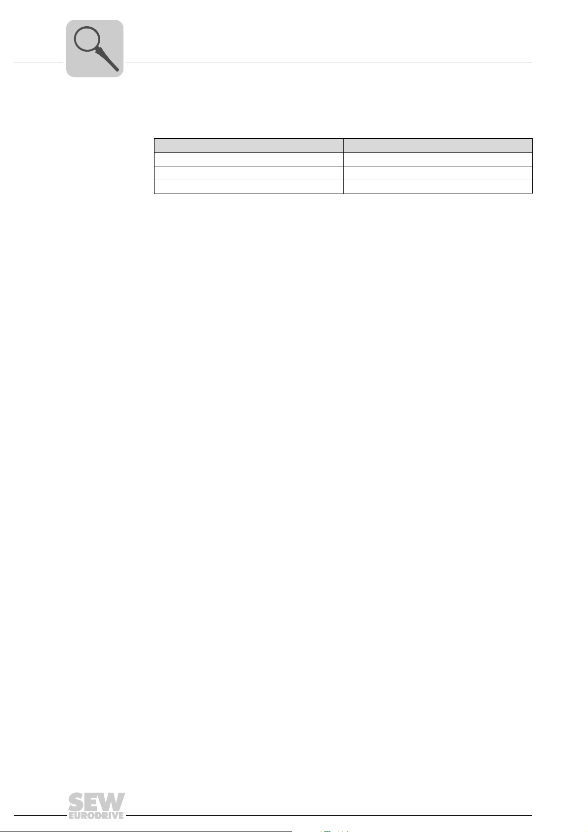
Module parameters Setting range
Transmit mode Acyclic / cyclic
Inhibit time 0 ... 5 ... 500 ms
Event time 0 ... 500 ms
• If the module parameter "TransmitMode" is set to "acyclic", process data will be
transmitted between MOVI-PLC
of modification. In this case, the module parameter "Event Time" indicates an additional cyclic transmission rate.
• If the module parameter "TransmitMode" is set to "cyclic", the "Event Time" indicates
the transmission rate for cyclic process data transmission.
• The module parameter "Inhibit Time" indicates in all cases a minimum duration
between process data transmissions.
®
controller and MOVI-PLC® I/O system in the event
26
Manual – MOVI-PLC® I/O System
Page 27
Unit Design and Technical Data of the MOVI-PLC® I/O System
ODO81B digital output module
4.4 ODO81B digital output module
Part number 1821 482 7
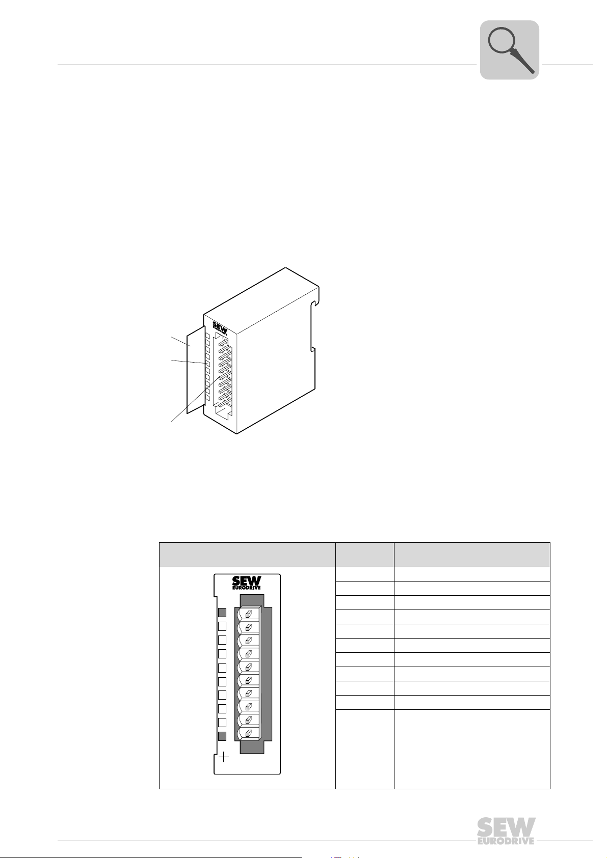
Description The ODI81B digital output module has 8 binary outputs, each one with an LED to
indicate the status.
• 8 binary outputs, galvanically isolated from the backplane bus
• Power supply voltage DC 24 V
• Output current DC 0.5 A
• Status indicated by LED
[1]
1
[2]
[3]
2
3
4
5
6
7
8
9
I0
4
Connector assignment
[1] Label for the bit address with description
[2] LED status indicator
[3] Connector strip
ODO81B Ter mi-
nal/LED
1 Power supply voltage DC 24 V
2 Binary output 0
3 Binary output 1
L+
0
1
2
3
4
5
6
7
F
X3
45
ODO81B
DO 8xDC24V, 0,5 A
1
2
3
4
5
6
7
8
9
10
4 Binary output 2
5 Binary output 3
6 Binary output 4
7 Binary output 5
8 Binary output 6
9 Binary output 7
10 Weight
LED +
LED F
LED 0 ... 7
62068AXX
62059AXX
Assignment/description
Green: DC 24 V present
Red: An error occurred
Green: Binary output active
Manual – MOVI-PLC® I/O System
27
Page 28
4
Unit Design and Technical Data of the MOVI-PLC® I/O System
ODO81B digital output module
LED + The "+" LED lights up green if the DC 24 V supply voltage is present.
LED 0 ... 7 Status
LEDs 0 ... 7 light up green if a binary output is active.
display
'F' LED The "F" LED lights up red if an error occurs caused by overload, overheating, or short
circuit.
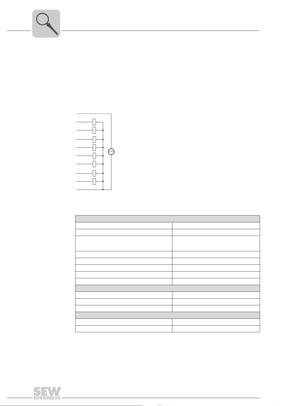
Wiring diagram
1
2
3
4
5
6
7
8
9
10 M
L+
DC 24V
62062AXX
Technical data
Electrical data of ODI81B
Number of binary outputs 8
Rated load voltage DC 24 V (20.4 ... 28.8 V)
Current consumption
at L+ without load
from backplane bus
Output current per channel 0.5 A short-cirucit proof
Total current 4 A
Voltage supply DC 24 V (20.4 V ... 28.8 V)
Galvanic isolation 500 V
Status indicator via LEDs located on the front
Programming data
Input data Output data 1 byte
Diagnostic data -
Dimensions and weight
Dimensions (W ×H ×D) [mm] 25.4 × 76 × 88
Weight 50 g
DC 10 mA
DC 70 mA
rms
(field voltage to the bus)
28
Manual – MOVI-PLC® I/O System
Page 29

Unit Design and Technical Data of the MOVI-PLC® I/O System
ODO81B digital output module
Parameter setting Make the following settings in the module parameters (→ section 5.6). The settings refer
to up to eight ODO81B digital output modules of the PLC configuration entry. Default
settings are printed in bold.
Module parameters Setting range
Transmit mode Acyclic / cyclic
Inhibit time 0 ... 5 ... 500 ms
Event time 0 ... 500 ms
4
• If the module parameter "TransmitMode" is set to "acyclic", process data will be
transmitted between MOVI-PLC
of a modification. In this case, the module parameter "Event Time" indicates an
additional cyclic transmission rate.
• If the module parameter "TransmitMode" is set to "cyclic", the "Event Time" indicates
the transmission rate for cyclic process data transmission.
• The module parameter "Inhibit Time" indicates in all cases a minimum duration
between process data transmissions.
®
controller and MOVI-PLC® I/O system in the event
Manual – MOVI-PLC® I/O System
29
Page 30
4
Unit Design and Technical Data of the MOVI-PLC® I/O System
OAI41B analog input module (voltage)
4.5 OAI41B analog input module (voltage)
Part number 1821 483 5
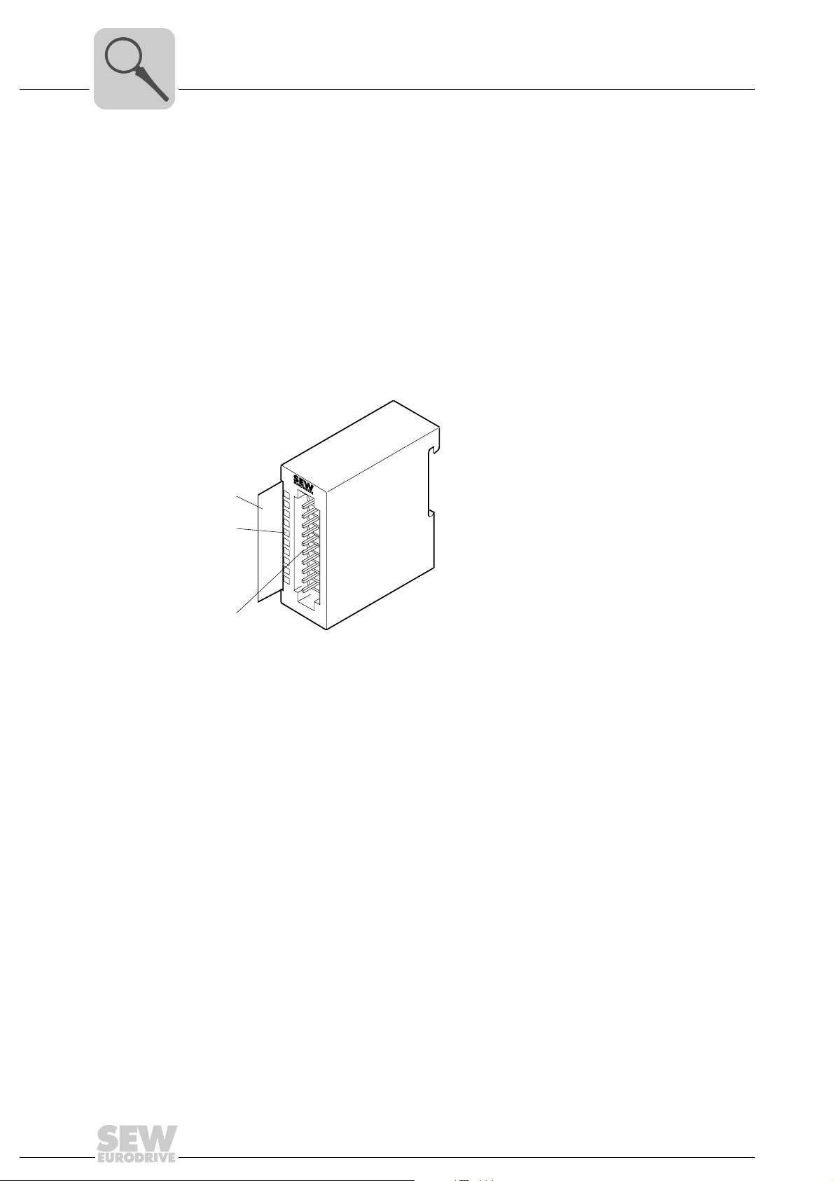
Description The OAI41B analog input module has 4 inputs, each with an LED to indicate the status.
The OAI41B input module requires a total of 8 bytes of the process image for the input
data (2 bytes per channel). The channels on the OAI41B input module are galvanically
isolated from the backplane bus by means of DC/DC converters.
• 4 analog inputs; channels galvanically isolated from the backplane bus
• The different channels can be configured individually and can be deactivated
• Suitable for encoders with ±10 V
• LED status indicator
[1]
1
[2]
[3]
2
3
4
5
6
7
8
9
I0
[1] Label for the bit address with description
[2] LED status indicator
[3] Connector strip
62059AXX
30
Manual – MOVI-PLC® I/O System
Page 31
Connector assignment
Unit Design and Technical Data of the MOVI-PLC® I/O System
OAI41B analog input module (voltage)
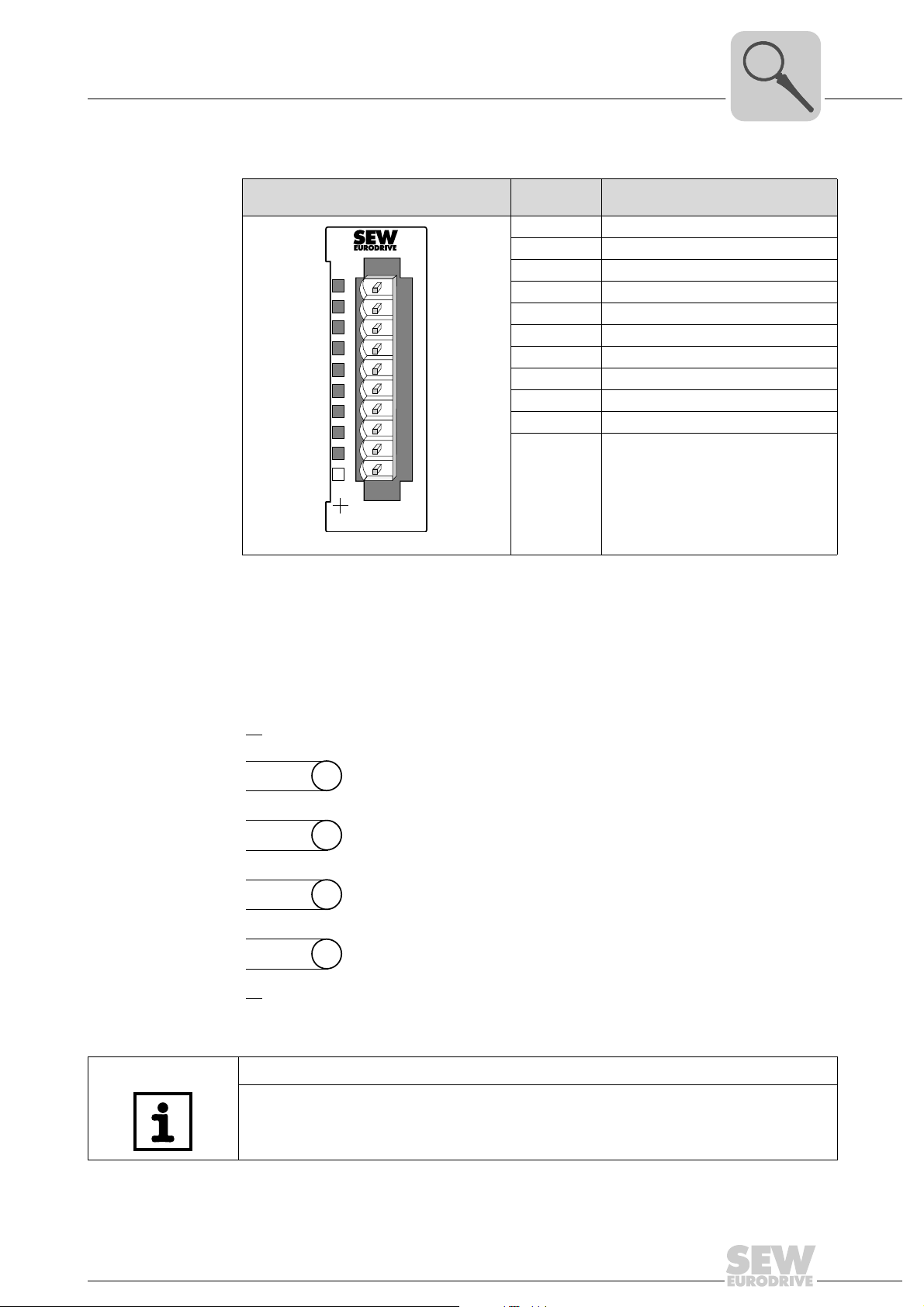
OAI41B Termi -
nal/LED
1 Not assigned
2 Positive connection channel 0
3 Ground channel 0
SF
X2
34
AI 4x12Bit Volt
1
2
3
4
5
6
7
8
9
10
OAI41B
62053AXX
4 Positive connection channel 1
5 Ground channel 1
6 Positive connection channel 2
7 Ground channel 2
8 Positive connection channel 3
9 Ground channel 3
10 Not assigned
'SF' LED Lights up red if
Assignment/description
• parameters are set incorrectly
• the upper or lower limit of the control
range is exceeded
4
'SF' LED The 'SF' LED lights up red if
• the upper or lower limit of the control range is exceeded
• parameters are set incorrectly
Wiring diagram
1
2
3
4
5
6
7
8
9
10
V
V
V
V
62063AXX
NOTE
Connect temporarily unused inputs with activated channel to the associated ground to
obtain defined values at these channels.
Manual – MOVI-PLC® I/O System
31
Page 32
4
Unit Design and Technical Data of the MOVI-PLC® I/O System
OAI41B analog input module (voltage)
Function assignment
You set the functions in the PLC Editor in the PLC configuration in the module parameters of the I/O module (→ section "Parameter setting of I/O modules"). Default settings
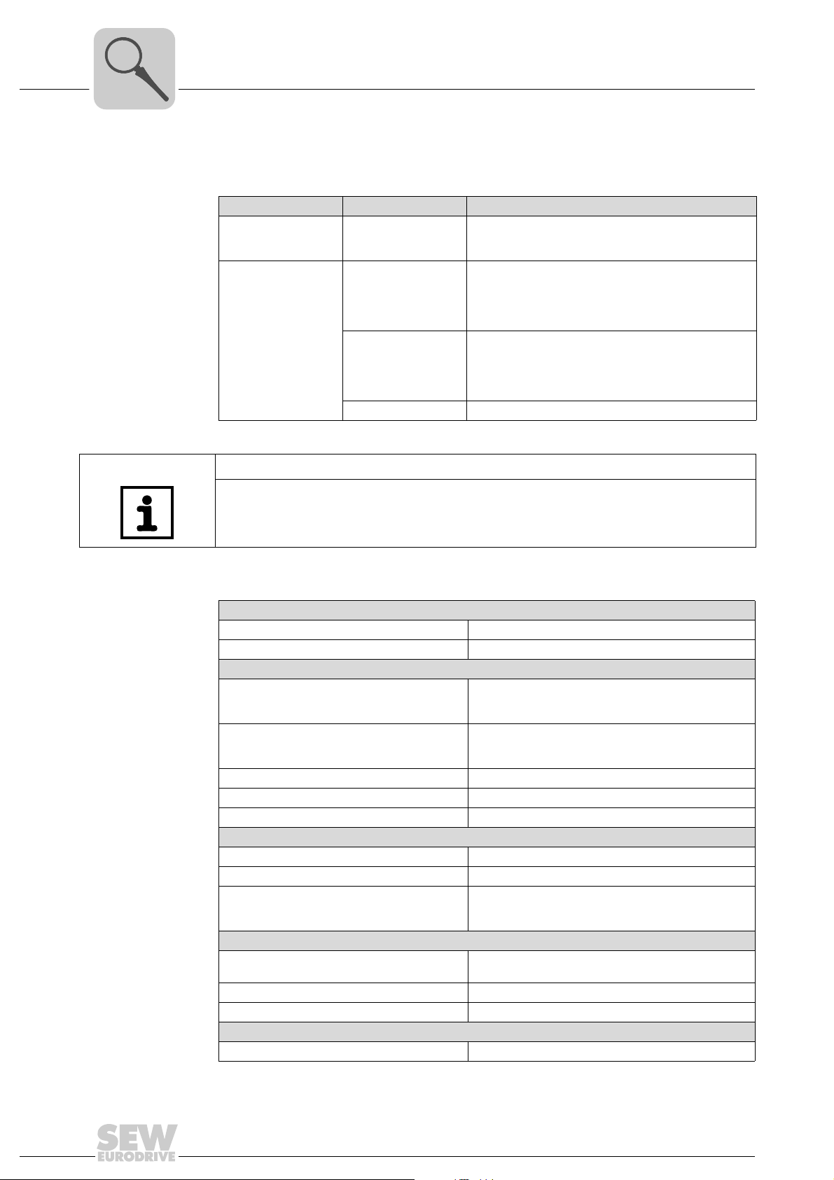
are printed in bold.
Module parameters Setting range Description/measuring range/representation
Event time 0 ... 10 ... 500 ms The "Event time" is used to set the transmission rate for
–10 ... 10 V
(–27648 ... 27648)
Mode channel 1 ... 4
–10 ... 10 V
(–16348 ... 16348)
Not active -
cyclic data transmission between MOVI-PLC
MOVI-PLC
DC ±11. 76 V
DC 11.76 V = Max. value overdrive range (32511)
DC –10 V ... 10 V = Rated range (–27648 ... 27648)
DC –11.76 V = Max. value underdrive range (–32512)
Two’s complement
DC ±12.50 V
DC 12.50 V = Max. value overdrive range (20480)
DC –10 V ... 10 V = Rated range (–16384 ... 16384)
DC –12.50 V = Min. value underdrive range (–20480)
Two’s complement
®
I/O system.
®
and
NOTE
The default setting of the I/O module OAI41B is "–10 ... 10 V (–27648 ... 27648)".
Technical data
Electrical data of OAI41B
Number of analog inputs 4
Cable length (shielded) 200 m
Voltages, currents, potentials
Galvanic isolation
Channel/backplane bus
between the channels
Permitted potential difference
between inputs
between inputs and M
Insulation tested at DC 500 V
Current consumption from backplane bus DC 120 mA
Power loss of the I/O module 0.6 W
Analog value generation
Measuring principle SAR (successive approximation)
Parameterizable Yes
Conversion time/resolution (per channel)
Basic conversion time (ms)
Resolution (bit) including overdrive range
Interference suppression, error limits
Interference suppression for f = n × (f1±1 %)
(f1 = interfering frequency; n = 1, 2, ...)
Common-mode interference (U
Interference between inputs > 50 dB
Operational limits (over entire temperature range, referred to input)
Voltage input Measuring range ±10 V / tolerance ±0.2 %
(U
internal
)
iso
< 2 V) > 80 dB
CM
Yes
No
DC 2 V
DC 75 V/AC 60 V
n×2ms
13 bit
f = 50 Hz ... 400 Hz
32
Manual – MOVI-PLC® I/O System
Page 33
Unit Design and Technical Data of the MOVI-PLC® I/O System
OAI41B analog input module (voltage)
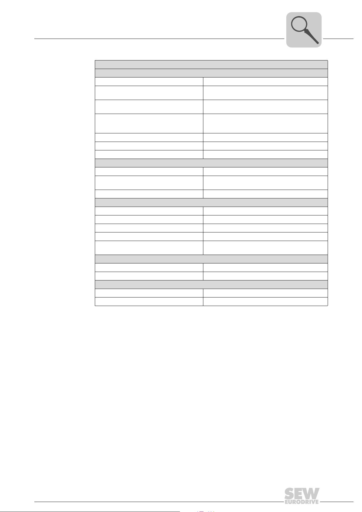
Electrical data of OAI41B
Basic error limit (operational limit at 25 °C, referred to input)
Voltage input Measuring range ±10 V / tolerance ±0.1 %
Temperature error
(referred to input)
Linearity error
(referred to input range)
Repeatability
(under steady-state conditions, at 25 °C,
referred to input range)
Diagnostics No
Diagnostics interrupt No
Fault display for group fault 'SF' LED (red)
Encoder selection data
Voltage Input range: ±10 V/input resistance: 100 kΩ
Permitted input voltage for voltage input
(destruction limit)
Voltage measurement Possible
Permitted ambient conditions
Operating temperature 0 °C ... 60 °C
Transport and storage temperature –25 °C ... 70 °C
Relative humidity 95 % without condensation
vibration and shock resistance According to IEC 68000-2/IEC 68000-2-27
EMC resistance
ESD/burst
Programming data
Input data 8 bytes (1 word per channel)
Output data -
Dimensions and weight
Dimensions (W ×H ×D) [mm] 25.4 × 76 × 88
Weight ca. 80 g
±0.005 %/K
±0.02 %
±0.05 %
Max. 30 V
According to IEC 61000-4-2
IEC 61000-4-2/IEC 61000-4-4 (up to level 3)
4
Manual – MOVI-PLC® I/O System
33
Page 34
4
Unit Design and Technical Data of the MOVI-PLC® I/O System
OAI42B analog input module (current)
4.6 OAI42B analog input module (current)
Part number 1821 484 3
Description The analog input module OAI42B has 4 inputs. Their functions can be configured
individually. The OAI42B input module requires a total of 8 bytes of the process image
for the input data (2 bytes per channel). The channels on the OAI42B input module are
galvanically isolated from the backplane bus by means of DC/DC converters.
• 4 analog inputs; channels galvanically isolated from the backplane bus
• The different channels can be configured individually and can be deactivated.
• Suitable for encoders with 4 ... 20 mA, ±20 mA
• LED status indicator
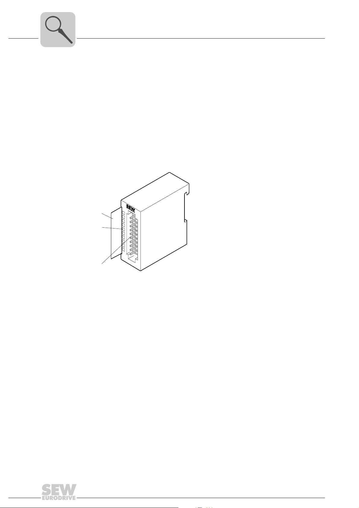
[1]
1
[2]
[3]
2
3
4
5
6
7
8
9
I0
[1] Label for the bit address with description
[2] LED status indicator
[3] Connector strip
62059AXX
34
Manual – MOVI-PLC® I/O System
Page 35
Connector assignment
Unit Design and Technical Data of the MOVI-PLC® I/O System
OAI42B analog input module (current)
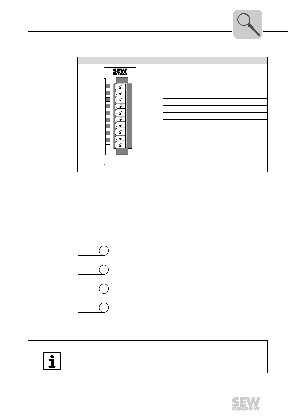
OAI42B Terminal/LED Assignment/description
1 Not assigned
2 Positive connection channel 0
3 Ground channel 0
SF
X2
34
OAI42B
AI 4x12Bit Curr
1
2
3
4
5
6
7
8
9
10
62055AXX
4 Positive connection channel 1
5 Ground channel 1
6 Positive connection channel 2
7 Ground channel 2
8 Positive connection channel 3
9 Ground channel 3
10 Not assigned
'SF' LED Lights up red if
• parameters are set incorrectly
• the upper or lower control limit is
exceeded
4
'SF' LED The 'SF' LED lights up red if
• the upper or lower control limit is exceeded
• if parameters are set incorrectly
Wiring diagram
1
2
3
4
5
6
7
8
9
10
A
A
A
A
62064AXX
NOTE
Connect temporarily unused inputs with activated channel to the associated ground to
obtain defined values at these channels.
Manual – MOVI-PLC® I/O System
35
Page 36
4
Unit Design and Technical Data of the MOVI-PLC® I/O System
OAI42B analog input module (current)
Function assignment
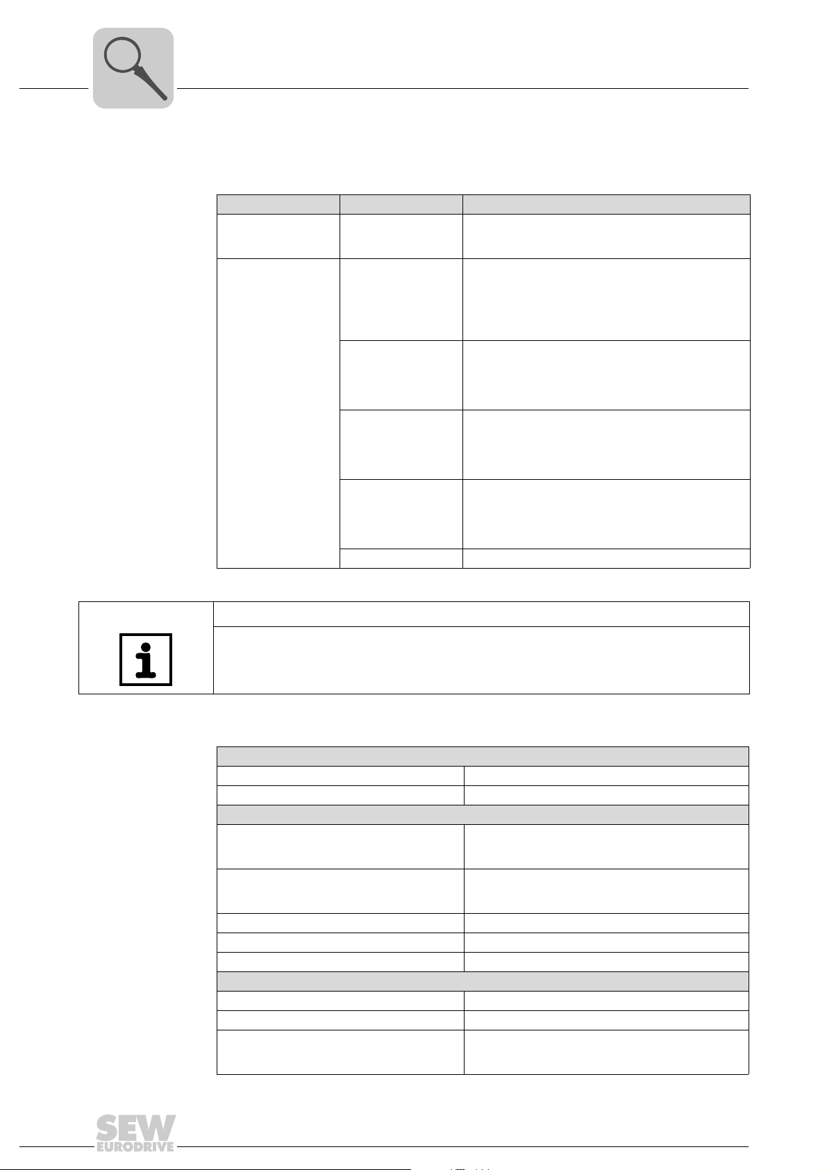
You set the functions in the PLC configuration in the PLC Editor in the module parameters of the I/O module (→ section "Parameter setting of I/O modules"). Default settings
are printed in bold.
Module parameters Setting range Description/measuring range/representation
Event time 0 ... 10 ... 500 ms The "Event time" is used to set the transmission rate for
4 ... 20 mA
(0 ... 27648)
–20 ... 20 mA
(–27648 ... 27648)
Mode channel 1 ... 4
4 ... 20 mA
(0 ... 16348)
–20 ... 20 mA
(–16384 ... 16384)
Not active -
cyclic data transmission between MOVI-PLC
MOVI-PLC
DC 1.185 ... 22.81 mA
DC 22.81 mA = Max. value overdrive range (32511)
DC 4 ... 20 mA = Rated range (0 ... 27648)
DC 1.185 mA = Minimum value underdrive range
(–4864)
Two’s complement
DC ±23.52 mA
DC 23.52 mA = Max. value overdrive range (32511)
DC –20 mA ... 20 mA = Rated range (–27648 ... 27648)
DC –23.52 V = Min. value underdrive range (–32512)
Two’s complement
DC 0.8 ... 24 mA
DC 24 mA = Max. value overdrive range (32511)
DC 4 .. 20 mA = Rated range (0 ... 16384)
DC 0.8 mA = Min. value underdrive range (–3277)
Two’s complement
DC ±25 mA
DC 25 mA = Max. value overdrive range (20480)
DC –20 mA ... 20 mA = Rated range (–16384 ... 16384)
DC –25 mA = Min. value underdrive range (–20480)
Two’s complement
®
I/O system.
®
and
Technical data
NOTE
The default setting of the I/O module OAI42B is "4 ... 20 mA (0 ... 27648)".
Electrical data of OAI42B
Number of analog inputs 4
Cable length (shielded) 200 m
Voltages, currents, potentials
Galvanic isolation
Channel/backplane bus
between the channels
Permitted potential difference
between inputs
between inputs and M
Insulation tested at DC 500 V
Current consumption from backplane bus DC 120 mA
Power loss of the I/O module 0.6 W
Analog value generation
Measuring principle SAR (successive approximation)
Parameterizable Yes
Conversion time/resolution (per channel)
Basic conversion time (ms)
Resolution (bit) including overdrive range
internal
(U
iso
)
Yes
No
DC 2 V
DC 75 V / AC 60 V
n×2ms
13 bit
36
Manual – MOVI-PLC® I/O System
Page 37
Unit Design and Technical Data of the MOVI-PLC® I/O System
OAI42B analog input module (current)
Electrical data of OAI42B
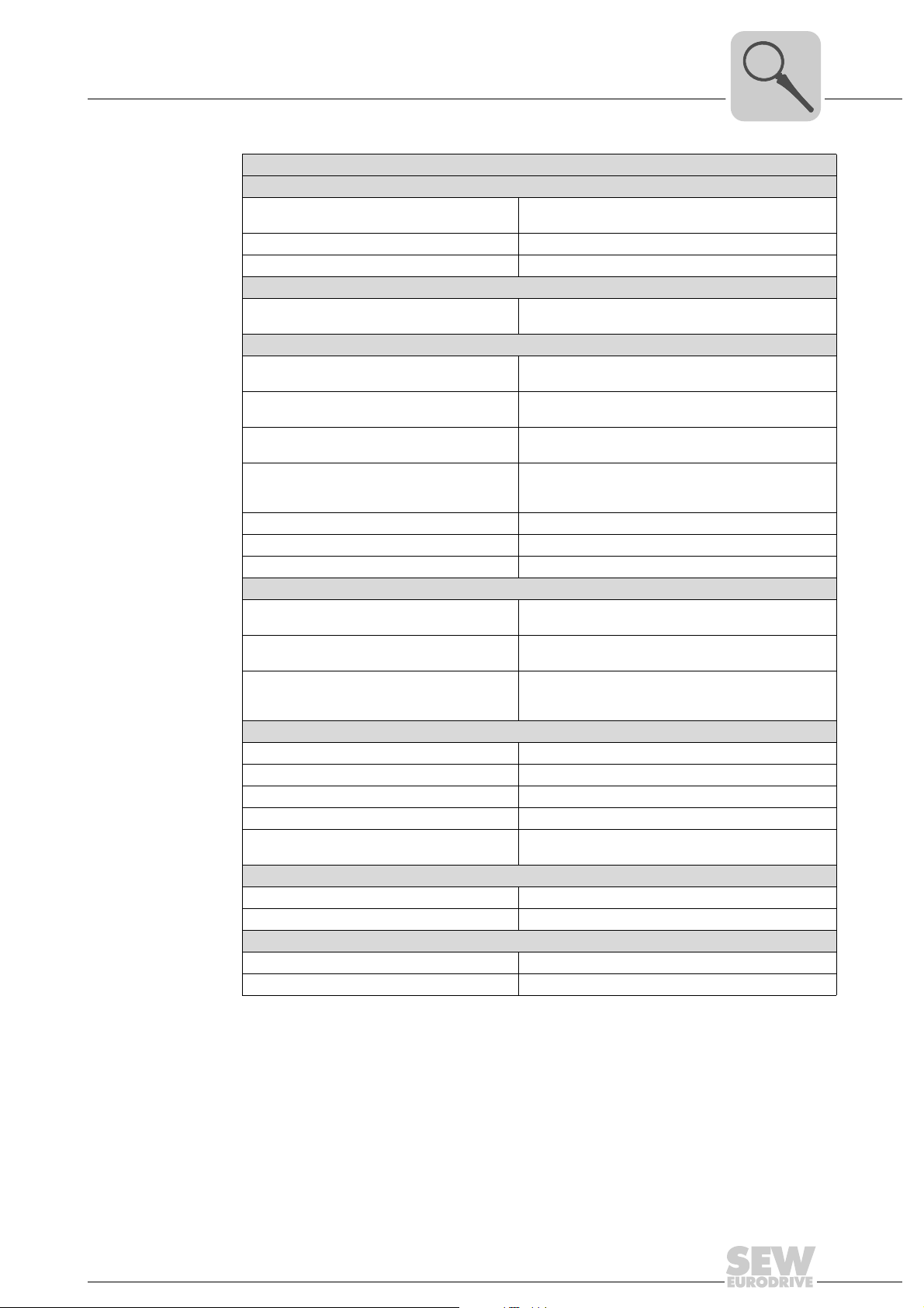
Interference suppression, error limits
Interference suppression for f = n × (f1±1 %)
(f1 = interfering frequency; n = 1, 2, ...)
Common-mode interference (U
Interference between inputs > 50 dB
Operational limits (over entire temperature range, referred to input)
Current input Measuring range ±20 mA / tolerance ±0.2 %
Basic error limit (operational limit at 25 °C, referred to input)
Current input Measuring range ±20 mA / tolerance ±0.1 %
Temperature error
(referred to input range)
Linearity error
(referred to input range)
Repeatability
(under steady-state conditions, at 25 °C,
referred to input range)
Diagnostics No
Diagnostics interrupt No
Fault display for group fault 'SF' LED (red)
Encoder selection data
Current Input range ±20 mA / input resistance 60Ω
Permitted input current for current input
(destruction limit)
Voltage measurement
as 2-wire transducer
as 4-wire transducer
Permitted ambient conditions
Operating temperature 0 °C ... 60 °C
Transport and storage temperature –25 °C ... 70 °C
Relative humidity 95 % without condensation
Vibration and shock resistance According to IEC 68000-2/IEC 68000-2-27
EMC resistance
ESD/burst
Programming data
Input data 8 bytes (1 word per channel)
Output data -
Dimensions and weight
Dimensions (W ×H ×D) [mm] 25.4 × 76 × 88
Weight ca. 80 g
< 2 V) > 80 dB
CM
f = 50 Hz ... 400 Hz
Measuring range 4 ... 20 mA / tolerance ±0.5 %
Measuring range 4 ... 20 mA / tolerance ±0.2 %
±0.005 %/K
±0.02 %
±0.05 %
Input range 4 ... 20μA / input resistance 60Ω
40 mA
Possible, with external supply
Possible
According to IEC 61000-4-2
IEC 61000-4-2/IEC 61000-4-4 (up to level 3)
4
Manual – MOVI-PLC® I/O System
37
Page 38
4
Unit Design and Technical Data of the MOVI-PLC® I/O System
OAI43B analog input module (multi-input)
4.7 OAI43B analog input module (multi-input)
Part number 1821 485 1
Description The OAI43B analog input module has 4 inputs. Their functions can be configured
individually. The OAI43B input module requires a total of 8 bytes of the process image
for the input data (2 bytes per channel). The channels on the OAI43B input module are
galvanically isolated from the backplane bus by means of DC/DC converters.
• The different channels can be configured individually and can be deactivated.
• The common signal inputs of the channels are not isolated from each other; the
permitted potential difference is up to 5 V.
• Diagnostic function
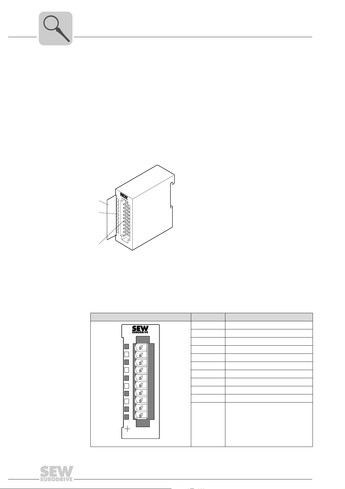
Connector assignment
[1]
1
[2]
[3]
2
3
4
5
6
7
8
9
I0
[1] Label for the bit address with description
[2] LED status indicator
[3] Connector strip
OAI43B Terminal/LED Assignment/description
1 Channel 0 with 4-wire connection
2 Positive connection channel 0
3 Ground channel 0
F0
F1
F2
F3
X2
34
AI 4x16Bit Mult
1
2
3
4
5
6
7
8
9
10
OAI43B
62057AXX
4 Positive connection channel 1
5 Ground channel 1
6 Positive connection channel 2
7 Ground channel 2
8 Positive connection channel 3
9 Ground channel 3
10 Channel 2 with 4-wire connection
LED F0 ... F3 Lights up red if
• an error occurs in one of the
channels
• an entry was made in the diagnostic
bytes
62059AXX
38
Manual – MOVI-PLC® I/O System
Page 39
Unit Design and Technical Data of the MOVI-PLC® I/O System
OAI43B analog input module (multi-input)
LEDs F0 ... F3 The LEDs F0 ... F3 light up red if
• an error occurs in one of the channels
• an entry was made in the diagnostic bytes
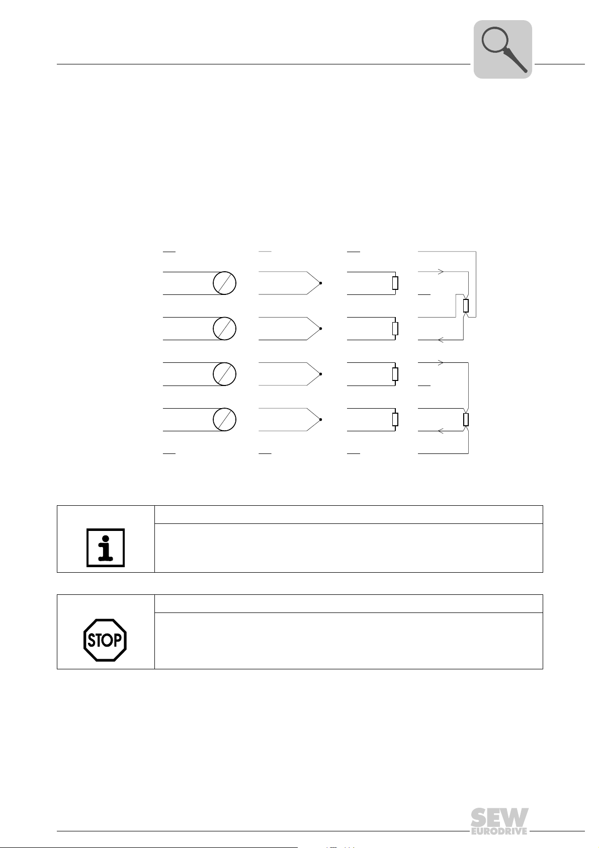
Wiring diagram The following figure shows the connection options for the various measuring ranges. For
an assignment to the measuring ranges, refer to the "Connection" column in the
"Function assignment" section.
[1] [2] [3] [4]
4
1
2
3
4
5
6
7
8
9
10
1
2
V
A
V
A
V
A
V
A
3
4
5
6
7
8
9
10
1
2
3
4
5
6
7
8
9
10
1
2
3
4
5
6
7
8
9
10
U-
I
U+
I
I
U+
I
U-
62065AXX
NOTE
Connect temporarily unused inputs with activated channel to the associated ground to
obtain defined values at these channels.
STOP!
Observe the following points to prevent the I/O module from being damaged:
• The parameterized measuring range must correspond with the connected encoder.
• Do not connect a voltage > DC 15 V to the input.
Manual – MOVI-PLC® I/O System
39
Page 40
4
Unit Design and Technical Data of the MOVI-PLC® I/O System
OAI43B analog input module (multi-input)
Function assignment
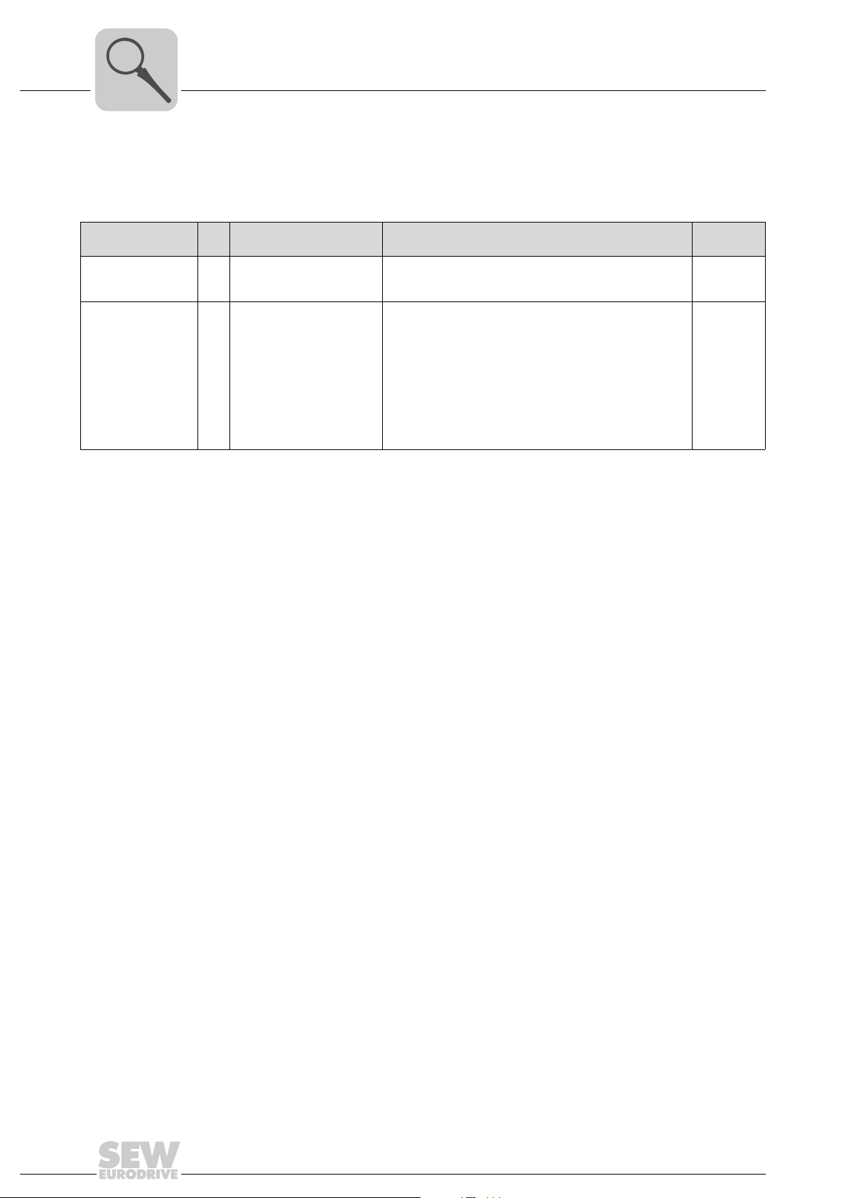
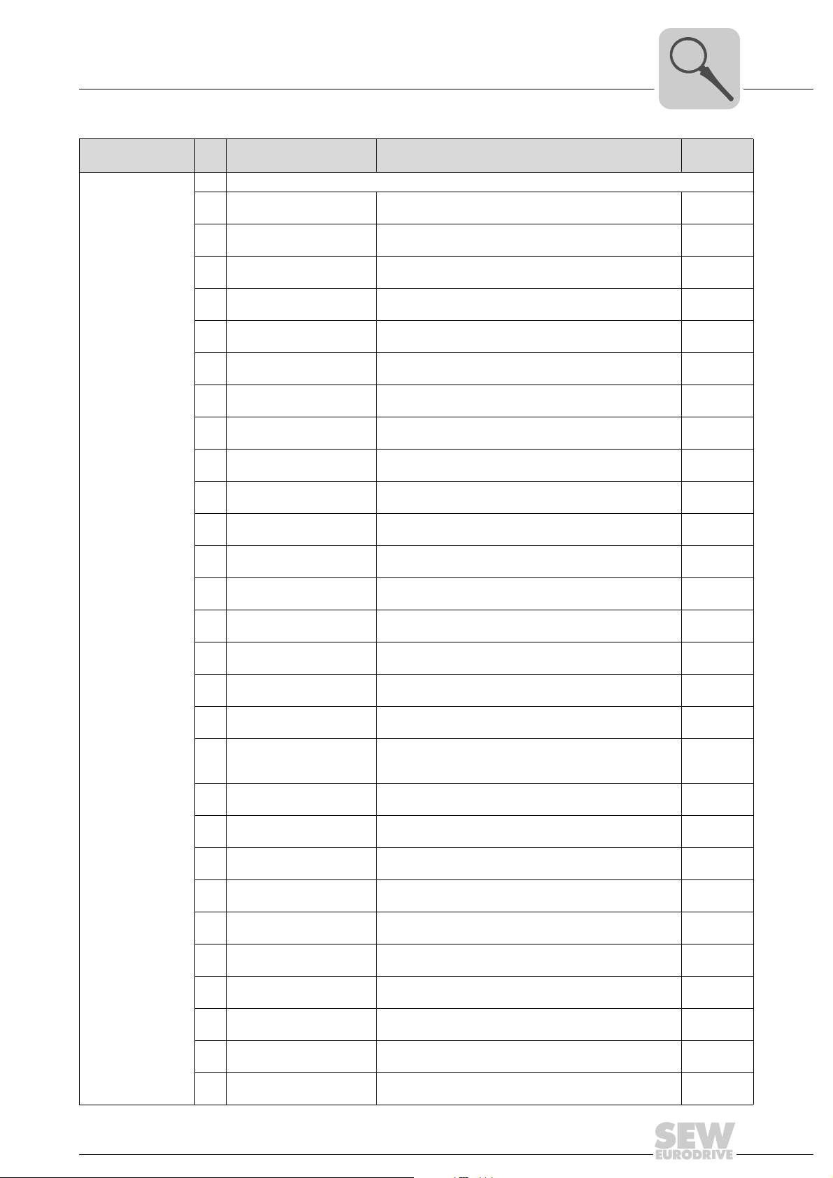
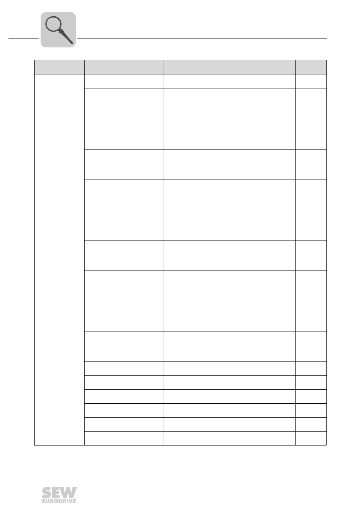
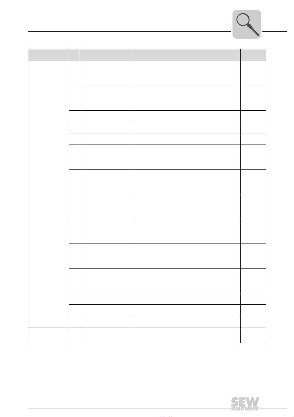
A function number is assigned to a channel by setting the module parameters (→ section "Parameter setting of I/O modules"). The function number 00
means the function
hex
number stored permanently in the parameter setting data is not influenced.
You can disable a channel by specifying FF
Module parameters No.
Event time - 0 ... 10 ... 500 ms The "Event time" is used to set the transmission rate for
Module mode - - The "Module mode" module parameter is used to set
Setting range / function Description / measuring range / representation Wiring
hex
cyclic data transmission between MOVI-PLC
®
PLC
I/O system.
whether the OAI43B analog input module is to generate a
diagnostics interrupt or not. In this case, the diagnostic
information will be output at the MPLC_ConnectSEWIOSystem_CAN function module (→ section "IEC pro-
gram"). You find more information in the "MPLCUtilities
Library for MOVI-PLC
Bit 0 ... 5, 7 : Reserved
Bit 6:
• 0 = Diagnostic interrupt disabled
• 1 = Diagnostic interrupt enabled
.
hex
®
" manual.
®
and MOVI-
diagram
-
-
40
Manual – MOVI-PLC® I/O System
Page 41
Unit Design and Technical Data of the MOVI-PLC® I/O System
OAI43B analog input module (multi-input)
4
Module parameters No.
hex
00 The function number in the permanently stored parameter setting data is not changed.
01 Pt100 in the 2-wire connec-
02 Pt1000 in the 2-wire con-
03 NI100 in the 2-wire connec-
04 NI1000 in the 2-wire con-
05 Resistance measurement
06 Resistance measurement
07 Resistance measurement
08 Resistance measurement
09 Pt100 in the 4-wire connec-
0A Pt1000 in the 4-wire con-
0B NI100 in the 4-wire connec-
0C NI1000 in the 4-wire con-
0D Resistance measurement
0E Resistance measuring 60 Ω
Mode channel 1 ... 4
0F Resistance measuring
10 Thermocouple type J
11 Thermocouple type K
12 Thermocouple type type
13 Thermocouple type R
14 Thermocouple type T
15 Thermocouple type S
16 Thermocouple type E
18 Thermocouple type J
19 Thermocouple type K, inter-
1A Thermocouple type N, inter-
1B Thermocouple type R, inter-
1C Thermocouple type T, inter-
1D Thermocouple type S, inter-
Setting range / function Description / measuring range / representation Wiring
tion
nection
tion
nection
60 Ω two-wire
60 Ω two-wire
3000 Ω two-wire
6000 Ω two-wire
tion
nection
tion
nection
60 Ω four-wire
four-wire
3000 Ω four-wire
1)
externally compensated
externally compensated
1)
N
, externally compen-
sated
externally compensated
1)
externally compensated
1)
externally compensated
1)
externally compensated
2)
internally compensated
nally compensated
nally compensated
nally compensated
nally compensated
nally compensated
1)
1)
–200 °C ... 850 °C
Unit: 1/10 °C; two’s complement
–200 °C ... 850 °C
Unit: 1/10 °C; two’s complement
–60 °C ... 250 °C
Unit: 1/10 °C; two’s complement
–60 °C ... 250 °C
Unit: 1/10 °C; two’s complement
60 Ω = end value (32767) [3]
600 Ω = end value (32767) [3]
3000 Ω = end value (32767) [3]
6000 Ω = end value (32767) [3]
–200 °C ... 850 °C
Unit: 1/10 °C; two’s complement
–200 °C ... 850 °C
Unit: 1/10 °C; two’s complement
–60 °C ... 250 °C
Unit: 1/10 °C; two’s complement
–60 °C ... 250 °C
Unit: 1/10 °C; two’s complement
60 Ω = end value (32767) [4]
600 Ω = end value (32767) [4]
3000 Ω = end value (32767) [4]
,
–210 °C ... 1200 °C
Unit: 1/10 °C, two’s complement
,
–270 °C ... 1372 °C
Unit: 1/10 °C, two’s complement
–270 °C ... 1300 °C
Unit: 1/10 °C, two’s complement
,
–50 °C ... 1769 °C
Unit: 1/10 °C, two’s complement
,
–270 °C ... 400 °C
Unit: 1/10 °C, two’s complement
,
–50 °C ... 1769 °C
Unit: 1/10 °C, two’s complement
,
–270 °C ... 1000 °C
Unit: 1/10 °C, two’s complement
,
–210 °C ... 1200 °C
Unit: 1/10 °C, two’s complement
–270 °C ... 1372 °C
Unit: 1/10 °C, two’s complement
–270 °C ... 1300 °C
Unit: 1/10 °C, two’s complement
–50 °C ... 1769 °C
Unit: 1/10 °C, two’s complement
–270 °C ... 400 °C
Unit: 1/10 °C, two’s complement
–50 °C ... 1769 °C
Unit: 1/10 °C, two’s complement
diagram
[3]
[3]
[3]
[3]
[4]
[4]
[4]
[4]
[2]
[2]
[2]
[2]
[2]
[2]
[2]
[2]
[2]
[2]
[2]
[2]
[2]
Manual – MOVI-PLC® I/O System
41
Page 42
4
Unit Design and Technical Data of the MOVI-PLC® I/O System
OAI43B analog input module (multi-input)
Module parameters No.
hex
1E Thermocouple type E, inter-
27 Voltage DC±50 mV
28 Voltage DC ±10 V
29 Voltage DC ±4V
2A Voltage DC ±400 mV
2B Voltage DC ±10 V
2C Current DC ±20 mA
Mode channel 1 ... 4
2D Current DC 4 ... 20 mA
2E Current DC 4 ... 20 mA
2F Current DC ±20 mA
32 Resistance measuring
33 Resistance measuring
35 Resistance measuring
36 Resistance measuring
37 Resistance measuring
38 Resistance measuring
Setting range / function Description / measuring range / representation Wiring
nally compensated
(–27648 ... 27648)
(–27648 ... 27648)
(–27648 ... 27648)
(–27648 ... 27648)
(–16384 ... 16384)
(–27648 ... 27648)
(0 ... 27648)
(0 ... 16384)
(–16384 ... 16384)
6000 Ω four-wire
6000 Ω four-wire
60 Ω two-wire
600 Ω two-wire
3000 Ω two-wire
6000 Ω two-wire
–270 °C ... 1000 °C
Unit: 1/10 °C, two’s complement
DC ±58.79 mV
DC 58.79 mV = Max. value overdrive range (32511)
DC –50 ... 50 mV = Rated voltage (–27648 ... 27648)
DC –58.79 mV = Min. value underdrive range (–32512)
Two’s complement
DC ±11. 76 V
DC 11.76 V = Max. value overdrive range (32511)
DC –10 ... 10 V = Rated range (–27648 ... 27648)
DC –11.76 V = Min. value underdrive range (–32512) Two’s
complement
DC ±4.70 V
DC 4.70 V = Max. value overdrive range (32511)
DC –4 ... 4 V = Rated range (–27648 ... 27648)
DC –4.70 V = Min. value underdrive range (–32511)
Two’s complement
DC ±470 mV
DC 470 mV = Max. value overdrive range (32511)
DC –400 ... 470 mV = Rated range (–27648 ... 27648)
DC –470 mV = Min. value underdrive range (–32512)
Two’s complement
DC ±12.50 V
DC 12.50 V = Max. value overdrive range (20480)
DC –10 ... 10 V = Rated range (–16384 ... 16384)
DC –12.50 V = Min. value underdrive range (–20480)
Value and sign
DC ±23.52 mA
DC 23.52 mA = Max. value overdrive range (32511)
DC –20 ... 20 mA = Rated range (–27648 ... 27648)
DC –23.52 mA = Min. value underdrive range (–32512)
Two’s complement
DC 1.185 ... 22.81 mA
DC 22.81 mA = Max. value overdrive range (32511)
DC 4 ... 20 mA = Rated range (0 ... 27648)
DC 1.185 mA = Min. value underdrive range (–4864)
Two’s complement
DC 0.8 ... 24 mA
DC 24 mA = Max. value overdrive range (20480)
DC 4 ... 20 mA = Rated range (0 ... 16384)
DC 0.8 mA = Min. value underdrive range (–3277)
Value and sign
DC ±25 mA
DC 25 mA = Max. value overdrive range (20480)
DC –20 ... 20 mA = Rated range (–16384 ... 16384)
DC –25 mA = Min. value underdrive range (–20480)
Value and sign
6000 Ω = end value (32767)
6000 Ω = end value (6000)
60 Ω = end value (6000)
600 Ω = end value (6000)
3000 Ω = end value (30000)
6000 Ω = end value (6000)
diagram
[2]
[1]
[1]
[1]
[1]
[1]
[1]
[1]
[1]
[1]
[4]
[4]
[3]
[3]
[3]
[3]
42
Manual – MOVI-PLC® I/O System
Page 43
Unit Design and Technical Data of the MOVI-PLC® I/O System
OAI43B analog input module (multi-input)
4
Module parameters No.
Mode channel 1 ... 4
ModeControl channel 1 ... 4
1) The compensation of the neutralization must be implemented externally.
2) The compensation of the neutralization must be implemented externally. Connect the thermocuple conductors directly to the front connector. Where necessary, extend them using thermocouple extension cables.
Setting range / function Description / measuring range / representation Wiring
hex
3A Current DC ±20 mA
(–16384 ... 16384)
3B Voltage DC ±10 V
(–16384 ... 16384)
3D Resistance measuring
60 Ω four-wire
3E Resistance measuring
600 Ω four-wire
3F Resistance measuring
3000 Ω four-wire
57 Voltage DC ±50 mV DC ±50 mV
58 Voltage DC ±10 V DC ±11. 76 V
59 Voltage DC ±4V DC ±4.7 V
5A Voltage DC ±400 mV DC ±470 mV
5C Current DC ±20 mA DC ±23.51 mA
5D Current DC 4 ... 20 mA DC 1.185 ... 22.81 mA
62 Cu50 in the 2-wire connec-
tion
6A Cu50 in the 4-wire connec-
tion
FF Channel not active (dis-
abled)
DC ±25 mA
DC 25 mA = Max. value overdrive range (20480)
DC –20 ... 20 mA = Rated range (–16384 ... 16384)
DC –25 mA = Min. value underdrive range (–20480)
Two’s complement
DC ±12.50 V
DC 12.50 V = Max. value overdrive range (20480)
DC –10 ... 10 V = Rated range (–16384 ... 16384)
DC –12.50 V = Min. value underdrive range (–20480)
Two’s complement
60 Ω = end value (6000)
600 Ω = end value (6000)
3000 Ω = end value (30000)
DC 58.79 mV = Max. value overdrive range (5879)
DC –50 ... 50 mV = Rated range (–5000 ... 5000)
DC –58.79 mV = Min. value underdrive range (–5879)
Two’s complement
DC 11.76 V = Max. value overdrive range (11760)
DC –10 ... 10 V = Rated range (–10000 ... 10000)
DC –11.76 V = Min. value underdrive range (–11760)
Two’s complement
DC 4.7 V = Max. value overdrive range (4700)
DC –4 ... 4 V = Rated range (–4000 ... 4000)
DC –4.7 V = Min. value underdrive range (–4700)
Two’s complement
DC 470 mV = Max. value overdrive range (4700)
DC –400 ... 400 mV = Rated voltage (–4000 ... 4000)
DC –470 mV = Min. value underdrive range (–4700)
Two’s complement
DC 23.51 mA = Max. value overdrive range (23510)
DC –20 ... 20 mA = Rated range (–20000 ... 20000)
DC –23.51 mA = Min. value underdrive range (–23510)
Two’s complement
DC 22.81 mA = Max. value overdrive range (18810)
DC 4 ... 20 mA = Rated range (0 ... 16000)
DC 1.185 mA = Min. value underdrive range (–2815)
Two’s complement
–50 °C ... 150 °C
Unit: 1/10 °C, two’s complement
–50 °C ... 150 °C
Unit: 1/10 °C, two’s complement
--
The "ModeControl Channel 1 ... 4" module parameter is
used to set the conversion speed as well as averaging and
a Hüllfunktion.
diagram
[1]
[1]
[4]
[4]
[4]
[1]
[1]
[1]
[1]
[1]
[1]
[3]
[4]
-
Manual – MOVI-PLC® I/O System
43
Page 44
4
Unit Design and Technical Data of the MOVI-PLC® I/O System
OAI43B analog input module (multi-input)
NOTE
The default setting of the OAI43B I/O module is "–10 ... 10 V (–27648 ... 27648)".
Module parameter ModeControl
Channel 1 ... 4
Structure
The "ModeControl Channel 1 ... 4" module parameter is used to set the following
parameters:
• Conversion speed
• Mean value calculation
• Envelope function
Bit 0 ... 7 Resolution
Bit 3 ... 0: Conversion speed per channel
• 0000 = 15 conversions/s
• 0001 = 30 conversions/s
• 0010 = 60 conversions/s
• 0011 = 120 conversions/s
• 0100 = 170 conversions/s
• 0101 = 200 conversions/s
• 0110 = 3.7 conversions/s
• 0111 = 7.5 conversions/s
Bit 5 ... 4: Mean value calculation
• 00 = disabled
• 01 = use 2 of 3 values
• 10 = use 4 of 6 values
• 11 = disabled
Bit 7 ... 6: Envelope function
• 00 = disabled
• 01 = envelope ±8
• 10 = envelope ±16
• 11 = disabled
1) The values refer to single-channel operation. To calculate the conversion speed per channel for
multi-channel operation, divide the specified conversion speeds by the number of active channels.
1)
16
16
15
14
12
10
16
16
Conversion speed Use bit 0 ... 3 to set the conversion speed for each input channel. Note that the resolution
decreases with higher conversion speeds due to the reduced integration time. The data
transmission format remains the same. Only the least significant bits (LSBs) are no
longer relevant for the analog value.
44
Manual – MOVI-PLC® I/O System
Page 45
Unit Design and Technical Data of the MOVI-PLC® I/O System
OAI43B analog input module (multi-input)
4
Mean value
calculation
• Mean value function 2 of 3 values
After every measuring, the OAI43B analog input module calculates the mean value
of the last 3 values. The value most different from the mean value is discarded. The
remaining 2 values are averaged again. This value will then be provided as output
value.
• Mean value function 4 of 6 values
After every measuring, the OAI43B analog input module calculates the mean value
of the last 6 values. The two values most different from the mean value are discarded. The remaining 4 values are averaged again. This value will then be provided as
output value.
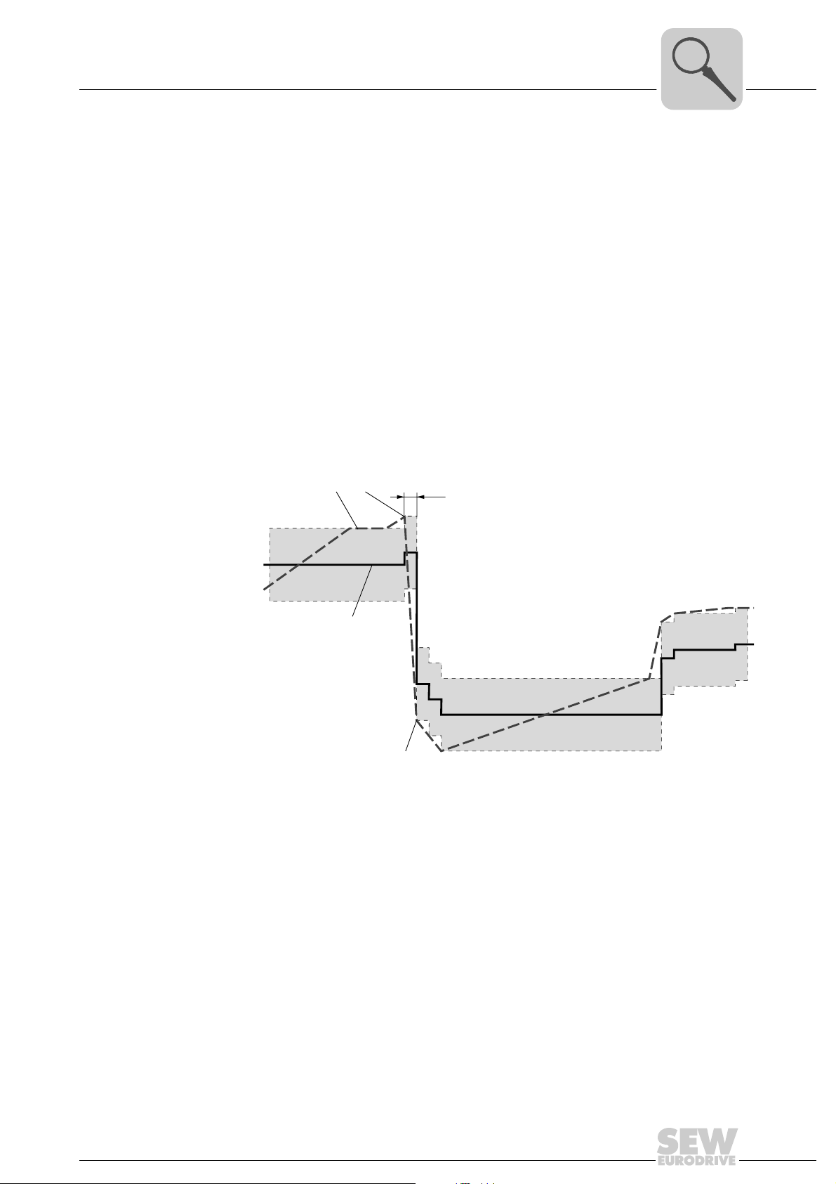
Envelope function The output value [3] is 'wrapped' with an envelope [A] with a parameterizable value. If
the measured value [1, 2, 4] lies over or under the envelope, the envelope [A] migrates
accordingly. The output value [3] is always the mean value of the envelope (→ following
figure).
[1] [2]
+8/+16
[B]
+8/+16
[A]
[3]
[A]
[A]
[4]
62091AXX
[1] Measured value within envelope → no envelope shift. The output value is the
mean value of the current upper and lower limit of the envelope.
[2] Measured value exceeds the envelope upwards → envelope shifts up by the
difference between "old" upper limit of the envelope and measured value. The
output value is the mean value of the "new" upper and lower limits of the
envelope.
[4] Measured value exceeds the envelope downwards → envelope shifts down by
the difference between "old" lower limit of the envelope and measured value. The
output value is the mean value of the "new" upper and lower limits of the
envelope.
[B] Integration time
Manual – MOVI-PLC® I/O System
45
Page 46
4
Technical data
Electrical data of OAI43B
Number of inputs
with 4-wire resistance-based sensor
Cable length (shielded) 200 m
Voltages, currents, potentials
Constant current for resistance-based sensor
Galvanic isolation
Permitted potential difference
Insulation tested at DC 500 V
Current consumption from backplane bus DC 280 mA
Power loss of the I/O module 1.4 W
Analog value generation Conversion time/resolution (per channel)
Measuring principle Sigma delta
Parameterizable Yes
Conversion speed [Hz] 200 170 120 60 30 15 7.5 3.7
Integration time [ms] 5 6 8 17 33 67 133 270
Basic conversion time [ms] 7 8 10 19 35 69 135 272
Resolution including overdrive range [Bit] 10 12 14 15 16 16 16 16
Interference voltage suppression for interfer-
ence frequency f1 [Hz]
Basic execution time of the I/O module (all
channels enabled) [ms]
Mean value calculation 2 of 3
Envelope function ±8 or ±16
Interference suppression, error limits
Interference suppression for f = n × (f1±1 %), (f1 = interfering frequency; n = 1, 2, ...)
Common-mode interference (U
Opposed-mode interference (peak value of
interference < rated value of input range)
Interference between inputs > 50 dB
Unit Design and Technical Data of the MOVI-PLC® I/O System
OAI43B analog input module (multi-input)
Channel/backplane bus
between the channels
between inputs (U
between inputs and M
Additional conversion time for wire break
monitoring [ms]
One-time service time per cycle (only with
thermocouple) [ms]
CM
)
internal
(U
)
iso
< 5 V) > 80 dB
CM
4
2
1.25 mA
Yes
No
DC 5 V
DC 75 V / AC 60 V
135
10
No 50 Hz and 60 Hz
28 32 40 76 140 276 540 1088
or
4 of 6
>80dB
46
Manual – MOVI-PLC® I/O System
Page 47
Unit Design and Technical Data of the MOVI-PLC® I/O System
OAI43B analog input module (multi-input)
Electrical data of OAI43B
Operational limits (only valid up to 120 W/s)
(over entire temperature range, referred to input range)
Measuring range Tolerance
Voltage input
Current input
Resistance
Resistance thermometer
Thermocouple Type J, K, N, R, S, E, T ± 1.5 %
Basic error limit (operational limit at 25 °C, referred to input)
Voltage input
Current input
Resistance
Resistance thermometer
Thermocouple Type J, K, N, R, S, E, T ±1.0 %
Temperature error during current measuring
(referred to input range)
Linearity error
(referred to input range)
Repeatability
(under steady-state conditions, at 25 °C,
referred to input range)
Temperature error of internal compensation ±1.5 %
Status, interrupts, diagnostics
Diagnostics interrupt Parameterizable
Diagnostic functions
Fault display for group fault
Diagnostic information can be read out
Encoder selection data
Voltage
HH±50 mV, ±400 mV, ±4V, ±10 V 20 MΩ
Current
HH±20 mA, 0 ... 20 mA, 4 ... 20 mA 50 Ω
Resistance
0 ... 60 Ω. 0 ... 600 Ω, 0 ... 3 kΩ , 0 ... 6 kΩ 20 MΩ
Resistance thermometer Pt100, Pt1000,
Ni100, Ni1000, Cu50 20 MΩ
Thermocouple
Type J, K, N, R, S, E, T 20 MΩ
Permitted input voltage for voltage input
(destruction limit)
±50 mV ±0.6 %
±400 mV, ±4V, ±10 V ±0.3 %
±20 mA ±0.3 %
0 ... 20 mA ±0.6 %
4 ... 20 mA ±0.8 %
0 ... 60 Ω ±0.8 %
0 ... 600 Ω, 0 ... 3 kΩ , 0 ... 6 kΩ±0.4 %
Pt100, Pt1000 ±0.4 %
Ni100, Ni1000 ±1.0 %
Cu50 ±1.4 %
±50 mV ±0.4 %
±400 mV, ±4V, ±10 V ±0.2 %
±20 mA ±0.2 %
0 ... 20 mA ±0.4 %
4 ... 20 mA ±0.5 %
0 ... 60 Ω ±0.4 %
0 ... 600 Ω, 0 ... 3 kΩ , 0 ... 6 kΩ±0.2 %
Pt100, Pt1000 ±0.2 %
Ni100, Ni1000 ±0.5 %
Cu50 ±0.7%
±0.005 %/K
±0.015 %/K
±0.05 %
Red 'SF' LED (per channel)
Possible
DC 25 V
4
Manual – MOVI-PLC® I/O System
47
Page 48
4
Unit Design and Technical Data of the MOVI-PLC® I/O System
OAI43B analog input module (multi-input)
Electrical data of OAI43B
Signal encoder connection
Voltage measurement
Current measurement
as 2-wire transducer
as 4-wire transducer
Resistance measurement
with 2-wire connection
with 4-wire connection
Linearization of characteristic curves
Parameterizable
for resistance thermometer
Thermocouples
Temperature compensation
Parameterizable
Internal temperature compensation
External temperature compensation
with comparison table (0 °C)
Unit for temperature measurement °C
Programming data
Input data 8 bytes (1 word per channel)
Dimensions and weight
Dimensions (W ×H ×D) [mm] 25.4 × 76 × 88
Weight 80 g
Possible
Possible, with external supply
Possible
Possible
Possible
Yes
Pt100, Pt1000, Ni100, Ni1000, Cu50
Type J, K, N, R, S, E, T
Yes
Possible
Possible
48
Manual – MOVI-PLC® I/O System
Page 49
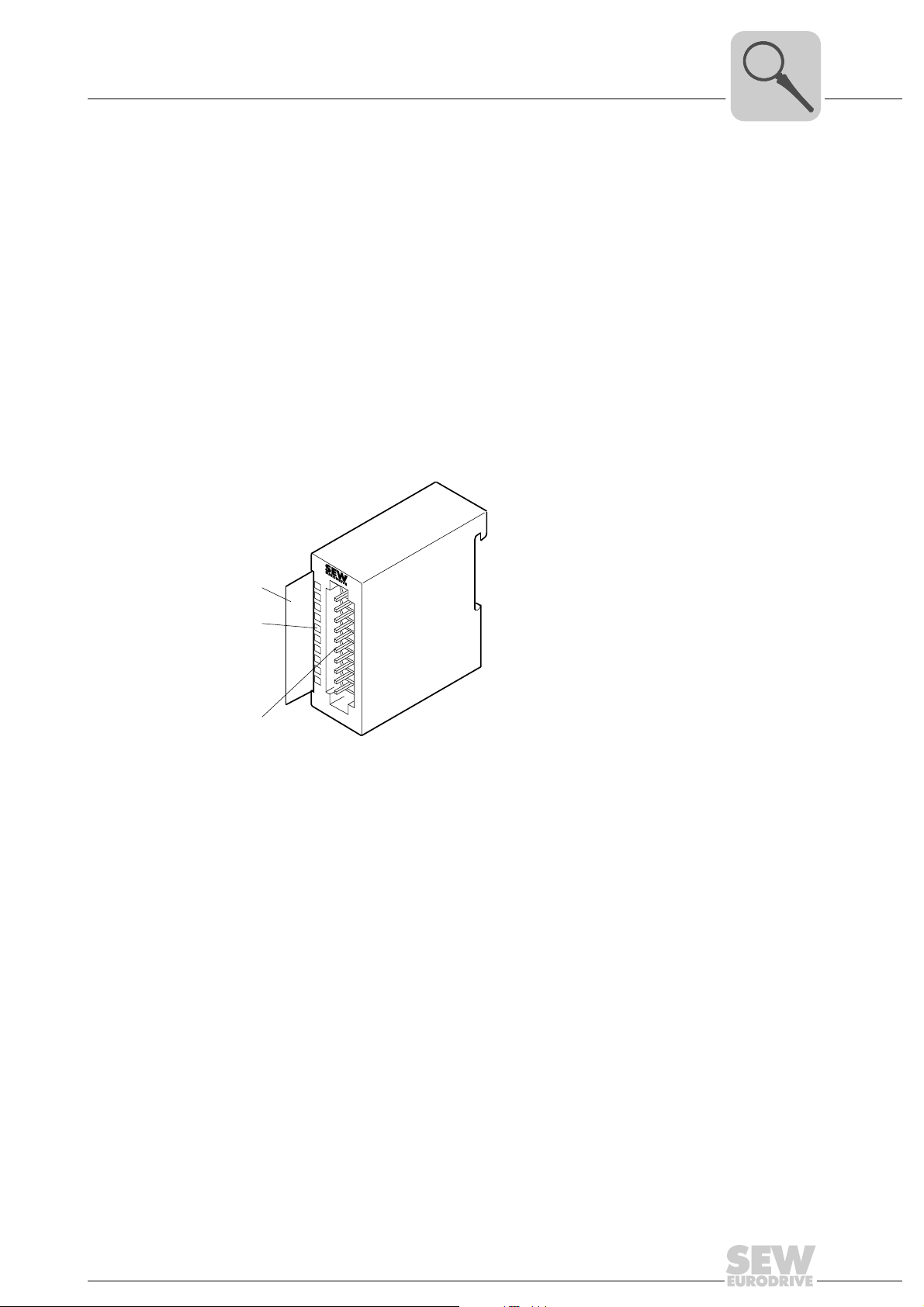
Unit Design and Technical Data of the MOVI-PLC® I/O System
OAO41B analog output module (voltage)
4.8 OAO41B analog output module (voltage)
Part number 1821 487 8
Description The OAO41B analog output module has 4 outputs. Their functions can be configured
individually. The OAO41B analog output module requires a total of 8 bytes of the
process image for the output data (2 bytes per channel). The channels on the OAO41B
output module are galvanically isolated from the backplane bus and power supply
voltage by means of DC/DC converters and optocouplers. The OAO41B analog output
module must be supplied with external DC 24 V.
• 4 analog outputs with common ground
• The different channels can be configured individually.
• Suitable for actuators with inputs ±10 V or 0 ... 10 V
• LED status indicator
4
[1]
1
[2]
[3]
2
3
4
5
6
7
8
9
I0
[1] Label for the bit address with description
[2] LED status indicator
[3] Connector strip
62059AXX
Manual – MOVI-PLC® I/O System
49
Page 50
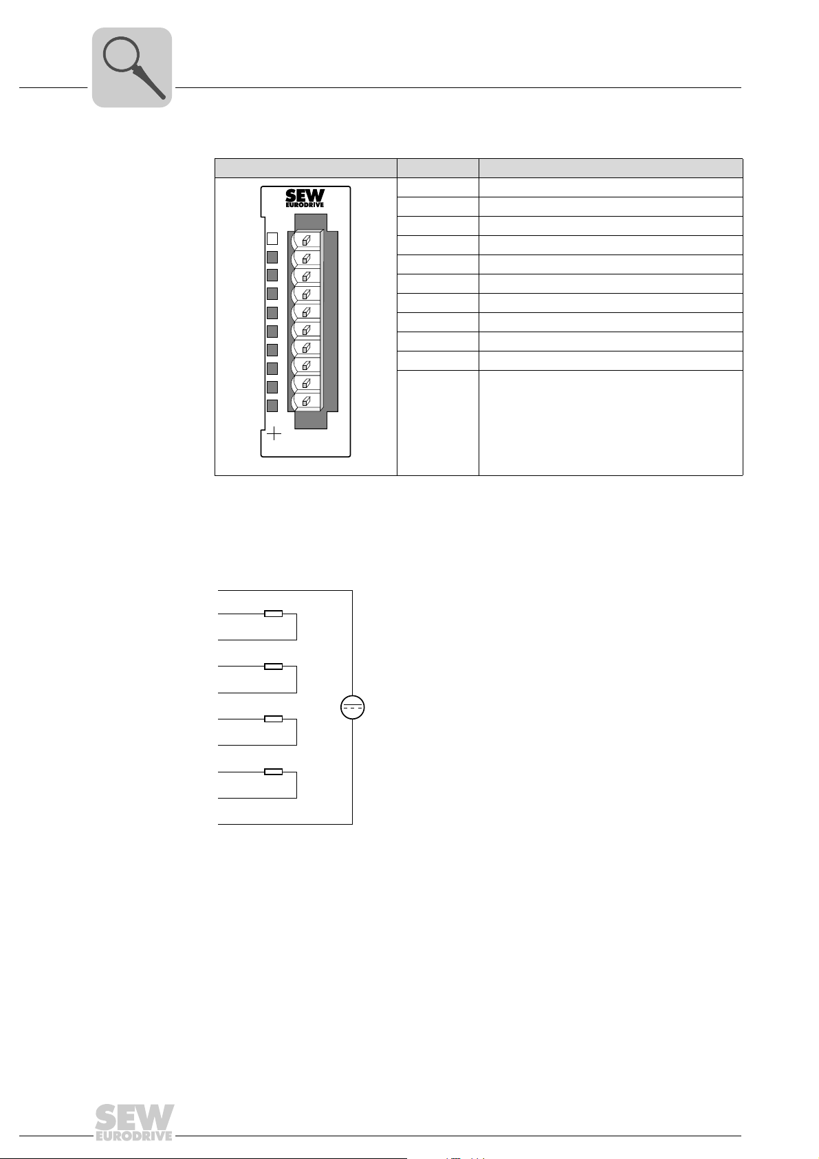
4
V
Connector assignment
Unit Design and Technical Data of the MOVI-PLC® I/O System
OAO41B analog output module (voltage)
OAO41B Terminal/LED Assignment/description
1 Power supply voltage DC 24 V
2 Positive connection channel 0
L+
X3
45
AO 4x12Bit Volt
1
2
3
4
5
6
7
8
9
10
OAO41B
62054AXX
3 Ground channel 0
4 Positive connection channel 1
5 Ground channel 1
6 Positive connection channel 2
7 Ground channel 2
8 Positive connection channel 3
9 Ground channel 3
10 Ground DC 24 V
LED + Green: DC 24 V present
LED L+ The L+ LED lights up green if the supply voltage DC 24 V is present.
Wiring diagram
1
2
3
4
5
6
7
8
9
10
L+
DC 24
M
62060AXX
50
Manual – MOVI-PLC® I/O System
Page 51
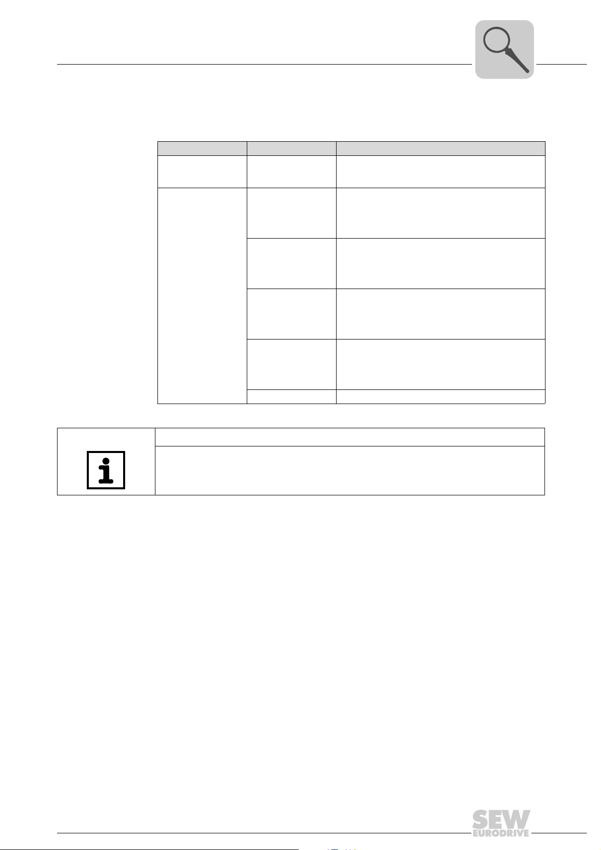
Unit Design and Technical Data of the MOVI-PLC® I/O System
OAO41B analog output module (voltage)
4
Function assignment
You set the functions in the PLC configuration in the PLC Editor in the module
parameters of the I/O module (→ section "Parameter setting of I/O modules"). Default
settings are printed in bold.
Module parameters Setting range Description/measuring range/representation
Event time 0 ... 10 ... 500 ms The "Event time" is used to set the transmission rate for
–10 ... 10 V
(–27648 ... 27648)
0 ... 10 V
(0 ... 27648)
Mode channel 1 ... 4
–10 V ... 10 V
(–16384 ... 16384)
0 ... 10 V
(0 ... 16384)
Not active -
cyclic data transmission between MOVI-PLC
MOVI-PLC
DC ±11. 76 V
DC 11.76 V = Max. value overdrive range (32511)
DC –10 V ... 10 V = Rated range (–27648 ... 27648)
DC –11.76 V = Min. value underdrive range (–32512)
Two’s complement
DC 0 ... 11.76 V
DC 11.76 V = Max. value overdrive range (32511)
DC 0 V ... 10 V = Rated range (0 ... 27648)
No underdrive range
Two’s complement
DC ±12.5 V
DC 12.5 V = Max. value overdrive range (20480)
DC –10 V ... 10 V = Rated range (–16384 ... 16384)
DC –12.5 V = Min. value underdrive range (–20480)
Two’s complement
DC 0 ... 12.5 V
DC 12.5 V = Max. value overdrive range (20480)
DC 0 V ... 10 V = Rated range (0 ... 16384)
No underdrive range
Two’s complement
®
I/O system.
®
and
NOTE
• The default setting of the OAO41B O/I module is "–10 ... 10 V (–27648 ... 27648)".
• Value "0" is output in all modes when the overdrive range or underdrive range is
exceeded.
Manual – MOVI-PLC® I/O System
51
Page 52
4
Technical data
Unit Design and Technical Data of the MOVI-PLC® I/O System
OAO41B analog output module (voltage)
Electrical data of OAO41B
Number of output channels 4
Cable length (shielded) 200 m
Supply voltage
Polarity reversal protection
Galvanic isolation
between channel/backplane bus
between channel/supply voltage
between the channels
between channel/load voltage L+
Permitted potential difference
between inputs and M
Insulation tested at DC 500 V
Current consumption
from backplane bus
from load voltage L+ (without load)
Power loss of the I/O module 2.7 W
Analog value generation output channels
Resolution
±10 V
0 ... 10 V
Cycle time (all channels) 700 μs
Setting time
Resistive load
Capacitive load
Inductive load
Interference suppression, error limits
Interference between outputs > 40 dB
Basic error limit (over entire temperature range,
referred to output range)
Voltage output Measuring range ±10 V / tolerance ±0.2 %
Basic error limit (operational limit at 25 °C,
referred to output range)
Voltage output Measuring range ±10 V / tolerance ±0.1 %
Temperature error
(referred to output range)
Linearity error
(referred to output range)
Repeatability
(under steady-state conditions at 25 °C,
referred to output range)
Output ripple
Bandwidth 0 to 50 kHz
(referred to output range)
Actuator selection data
Voltage Output ranges: ±10 V / 0 ... 10 V
Load impedance (in the rated range of the out-
put)
for voltage outputs
Capacitive load
Voltage output
Short-circuit proof
Short-circuit current
Destruction limit against externally applied volt-
ages/currents
Voltage at the output against M
Current
internal
(U
) DC 75 V / AC 60 V
iso
ANA
DC 24 V
Yes
Yes
Yes
No
Yes
DC 60 mA
DC 100 mA
11 bit + sign
11 bit
1.5 ms
3 ms
-
Measuring range 0 ... 10 V / tolerance ±0.4 %
Measuring range 0 ... 10 V / tolerance ±0.2 %
±0.01 %/K
±0.05 %
±0.05 %
±0.05 %
Min. 5 kΩ
Max. 1 μF
Yes
Max. 6 mA
Max. 15 V
Max. 30 mA
52
Manual – MOVI-PLC® I/O System
Page 53
Unit Design and Technical Data of the MOVI-PLC® I/O System
OAO41B analog output module (voltage)
Electrical data of OAO41B
Connection of the actuators
Voltage output 2-wire connection
Status, interrupts, diagnostics
Diagnostics interrupt Diagnostic functions Fault display for group fault Diagnostic information can be read out Substitute values can be switched in -
Programming data
Input data Output data 8 bytes (1 word per channel)
Diagnostic data -
Dimensions and weight
Dimensions (W ×H ×D) [mm] 25.4 × 76 × 88
Weight 100 g
4
Manual – MOVI-PLC® I/O System
53
Page 54
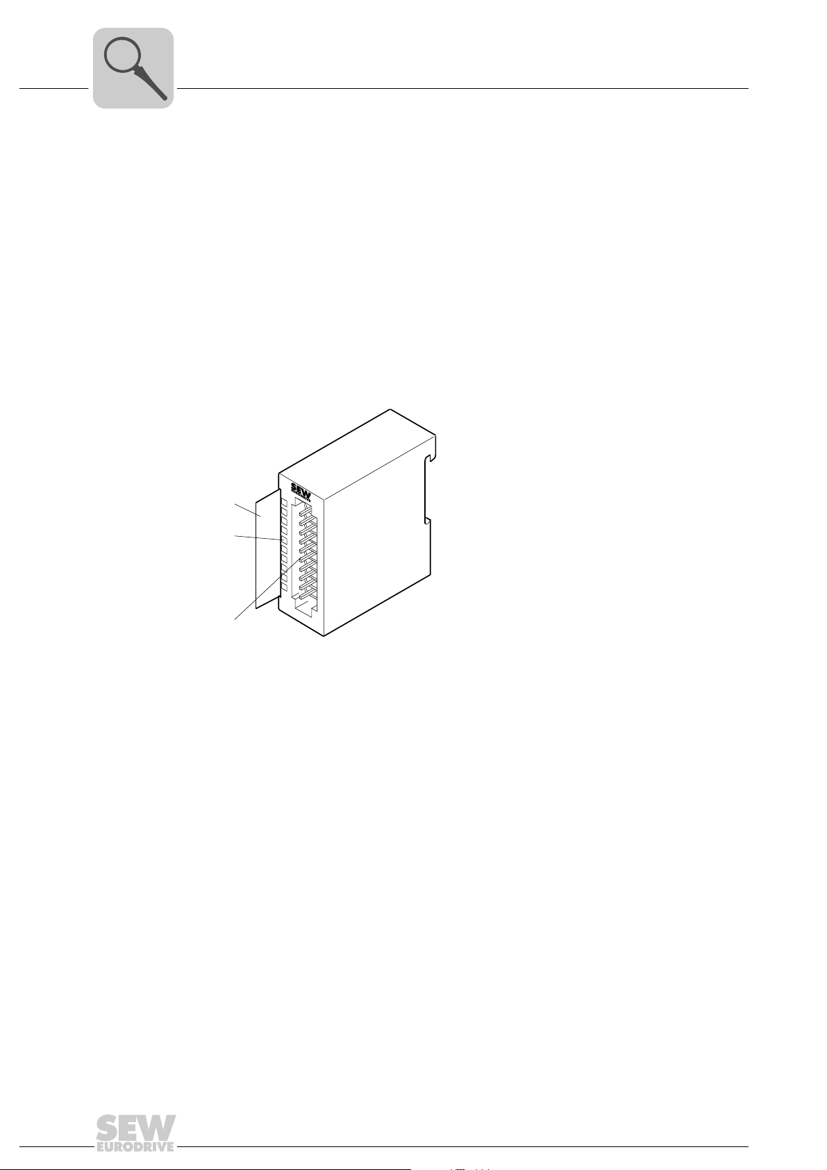
4
Unit Design and Technical Data of the MOVI-PLC® I/O System
OAO42B analog output module (current)
4.9 OAO42B analog output module (current)
Part number 1821 488 6
Description The OAO42B analog output module has 4 outputs. Their functions can be configured
individually. The OAO42B output module requires a total of 8 bytes of the process image
for the output data (2 bytes per channel). The channels on the OAO42B output module
are galvanically isolated from the backplane bus by means of DC/DC converters and
optocouplers. The OAO42B analog output module must be supplied with external
DC 24 V.
• 4 analog outputs with common ground
• The outputs can be configured individually.
• Suitable for actuators with inputs 0 ... 20 mA or 4 ... 20 mA
[1]
1
[2]
[3]
2
3
4
5
6
7
8
9
I0
[1] Label for the bit address with description
[2] LED status indicator
[3] Connector strip
62059AXX
54
Manual – MOVI-PLC® I/O System
Page 55
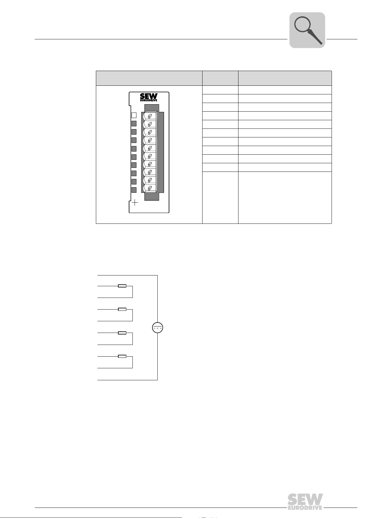
Connector
V
assignment
Unit Design and Technical Data of the MOVI-PLC® I/O System
OAO42B analog output module (current)
OAO42B Ter mi-
nal/LED
1 Power supply voltage DC 24 V
2 Positive connection channel 0
3 Ground channel 0
L+
X2
34
OAO42B
AO 4x12Bit Curr
1
2
3
4
5
6
7
8
9
10
62056AXX
4 Positive connection channel 1
5 Ground channel 1
6 Positive connection channel 2
7 Ground channel 2
8 Positive connection channel 3
9 Ground channel 3
10 Ground DC 24 V
LED + Green: DC 24 V present
Assignment/description
4
LED L+ The L+ LED lights up green if the supply voltage DC 24 V is present.
Wiring diagram
1
2
3
4
5
6
7
8
9
10
L+
DC 24
M
62060AXX
Manual – MOVI-PLC® I/O System
55
Page 56
4
Unit Design and Technical Data of the MOVI-PLC® I/O System
OAO42B analog output module (current)
Function assignment
You set the functions in the PLC configuration in the PLC Editor in the module parameters of the I/O module (→ section "Parameter setting of I/O modules"). Default settings
are printed in bold.
Module parameters Setting range Description/measuring range/representation
Event time 0 ... 10 ... 500 ms The "Event time" is used to set the transmission rate for
4 ... 20 mA
(0 ... 27648)
0 ... 20 mA
(0 ... 27648)
Mode channel 1 ... 4
4 ... 20 mA
(0 ... 16384)
0 ... 20 mA
(0 ... 16384)
Not active -
cyclic data transmission between MOVI-PLC
MOVI-PLC
DC 0 ... 22.81 mA
DC 22.81 mA = Max. value overdrive range (32511)
DC 4 ... 20 mA = Rated range (0 ... 27648)
DC 0 mA = Min. value underdrive range (–6912)
Two’s complement
DC 0 ... 23.52 mA
DC 23.52 mA = Max. value overdrive range (32511)
DC 0 ... 20 mA = Rated range (0 ... 27648)
No underdrive range
Two’s complement
DC 0 ... 24 mA
DC 24 mA = Max. value overdrive range (20480)
DC 4 .. 20 mA = Rated range (0 ... 16384)
DC 0 mA = Min. value underdrive range (–4096)
Two’s complement
DC0 ... 24 mA
DC 24 mA = Max. value overdrive range (20480)
DC 4 ... 20 mA = Rated range (0 ... 16384)
No underdrive range
Two’s complement
®
I/O system.
®
and
Technical data
NOTE
• The default setting of the OAO42B I/O module is "4 ... 20 mA (0 ... 27648)".
• The value "0" is output in all modes when the overdrive range or underdrive range
is exceeded.
Electrical data of OAO42B
Number of output channels 4
Cable length (shielded) 200 m
Supply voltage
Polarity reversal protection
Galvanic isolation
between channel/backplane bus
between channel/supply voltage
between the channels
between channel/load voltage L+
Permitted potential difference
between inputs and M
Insulation tested at DC 500 V
Current consumption
from backplane bus
from load voltage L+ (without load)
Power loss of the I/O module 1.5 W
internal
(U
) DC 75 V / AC 60 V
iso
DC 24 V
Yes
Yes
Yes
No
Yes
DC 60 mA
DC 50 mA
56
Manual – MOVI-PLC® I/O System
Page 57
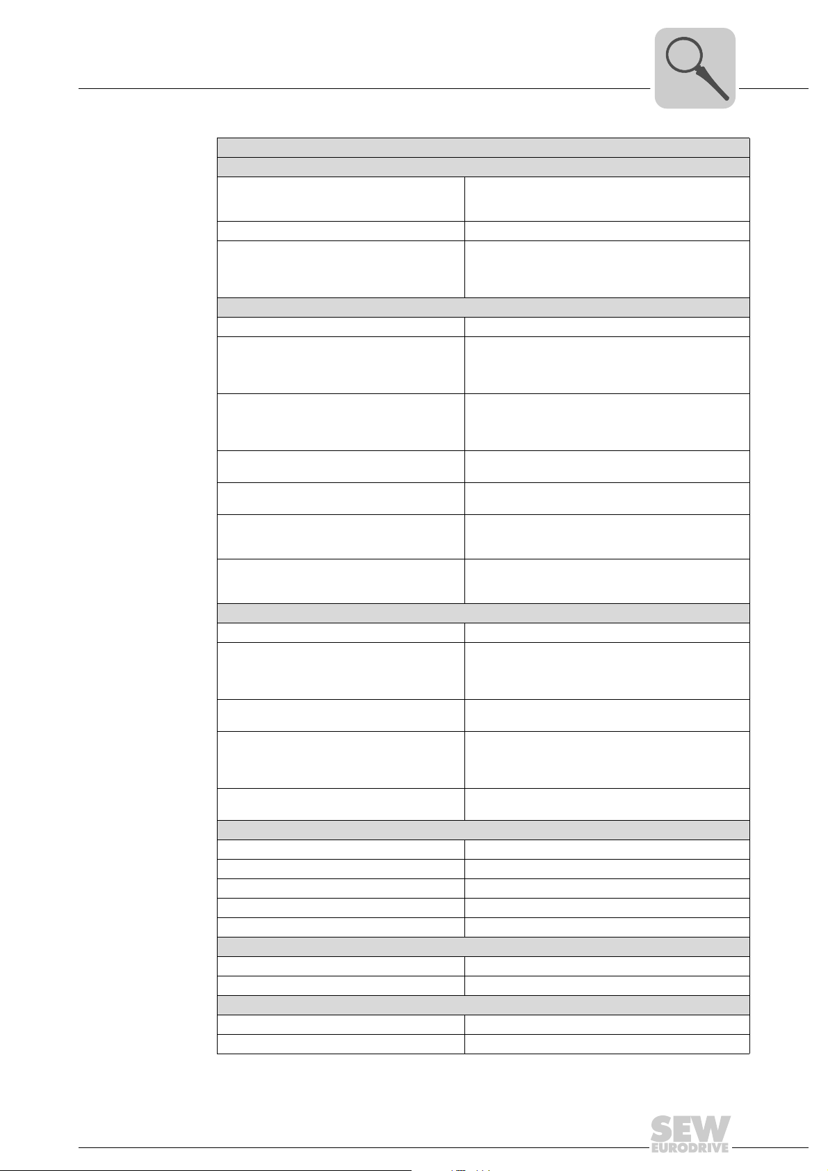
Unit Design and Technical Data of the MOVI-PLC® I/O System
OAO42B analog output module (current)
Electrical data of OAO42B
Analog value generation output channels
Resolution
0 ... 20 mA
4 ... 20 mA
Cycle time (all channels) 700 μs
Setting time
Resistive load
Capacitive load
Inductive load
Interference suppression, error limits
Interference between outputs > 40 dB
Basic error limit (over entire temperature range,
referred to output range)
Current output Measuring range 0 ... 20 mA / tolerance ±0.4 %
Basic error limit (operational limit at 25 °C,
referred to output range)
Current output Measuring range 0 ... 20 mA / tolerance ±0.2 %
Temperature error
(referred to output range)
Linearity error
(referred to output range)
Repeatability
(under steady-state conditions at 25 °C,
referred to output range)
Output ripple
Bandwidth 0 to 50 kHz
(referred to output range)
Actuator selection data
Current Output ranges: 0 ... 20 mA / 4 ... 20 mA
Load impedance (in the rated range of the out-
put)
for current outputs
Inductive load
Current output
No-load voltage DC 12 V
Destruction limit against externally applied volt-
ages/currents
Voltage at the output against M
Current
Connection of the actuators
Current output 2-wire connection
Status, interrupts, diagnostics
Diagnostics interrupt Diagnostic functions Fault display for group fault Diagnostic information can be read out Substitute values can be switched in -
Programming data
Input data Output data 8 bytes (1 word per channel)
Dimensions and weight
Dimensions (W ×H ×D) [mm] 25.4 × 76 × 88
Weight 100 g
ANA
12 bit
11 bit
0.03 ms
-
1.5 ms
Measuring range 4 ... 20 mA / tolerance ±0.5 %
Measuring range 4 ... 20 mA / tolerance ±0.3 %
±0.01 %/K
±0.05 %
±0.05 %
±0.05 %
Min. 350 Ω
Max. 10 mH
Max. 12 V
Max. 30 mA
4
Manual – MOVI-PLC® I/O System
57
Page 58
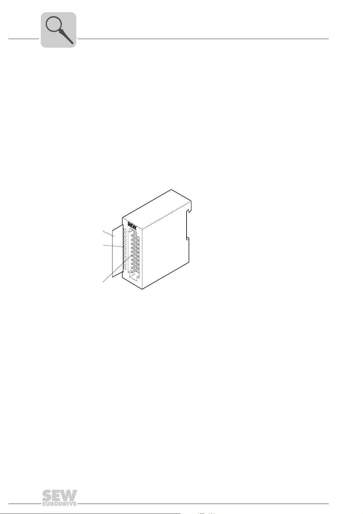
4
Unit Design and Technical Data of the MOVI-PLC® I/O System
OAO43B analog output module (multi-output)
4.10 OAO43B analog output module (multi-output)
Part number 1821 489 4
Description The OAO43B analog output module has 4 outputs. Their functions can be configured
individually. The OAO43B output module requires a total of 8 bytes of the process image
for the output data (2 bytes per channel). The values must be specified left-justified in
the two’s complement. The channels on the OAO42B output module are galvanically
isolated from the backplane bus by means of DC/DC converters.
• The outputs can be configured individually.
• Four outputs with common ground
• Suitable for actuators with inputs ±10 V, 1 ... 5 V, 0 ... 10 V, ±20 mA, 4 ... 20 mA or 0
... 20 mA
• Diagnostic LED and diagnostic function
[1]
1
[2]
[3]
2
3
4
5
6
7
8
9
I0
[1] Label for the bit address with description
[2] LED status indicator
[3] Connector strip
62059AXX
58
Manual – MOVI-PLC® I/O System
Page 59
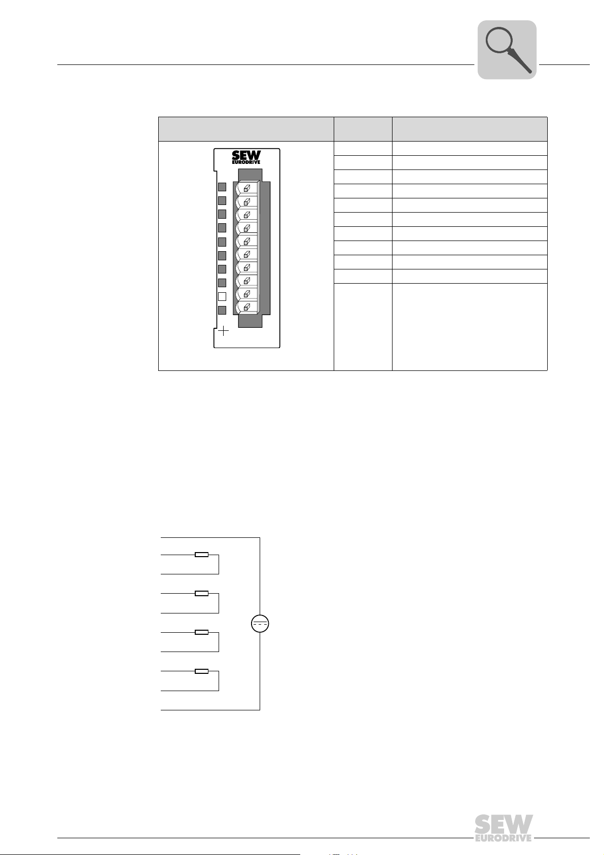
Connector
V
assignment
Unit Design and Technical Data of the MOVI-PLC® I/O System
OAO43B analog output module (multi-output)
OAO43B Ter mi-
nal/LED
1 Power supply voltage DC 24 V
2 Positive connection channel 0
3 Ground channel 0
SF
X2
34
AO 4x12Bit Mult
1
2
3
4
5
6
7
8
9
10
OAO43B
62058AXX
4 Positive connection channel 1
5 Ground channel 1
6 Positive connection channel 2
7 Ground channel 2
8 Positive connection channel 3
9 Ground channel 3
10 Ground DC 24 V
'SF' LED Lights up red if
Assignment/description
• the OAO43B output module is not
supplied with voltage
• a short-circuit occurs in the voltage
output
• a wire break occurs in the current
output
• the module contains an incorrect
parameter
4
'SF' LED The 'SF' LED lights up red if
• the OAO43B output module is not supplied with voltage
• a short-circuit occurs in the voltage output
• a wire break occurs in the current output
• a parameter in the module was set incorrectly
Wiring diagram
1
2
3
4
5
6
7
8
9
L+
DC 24
10
Manual – MOVI-PLC® I/O System
M
62060AXX
59
Page 60
4
Unit Design and Technical Data of the MOVI-PLC® I/O System
OAO43B analog output module (multi-output)
Function assignment
A function number is assigned to a channel by setting the module parameters (→ section "Parameter setting of I/O modules"). The function number 00
means the function
hex
number stored permanently in the parameter setting data is not influenced.
You can disable a channel by specifying FF
Module parameters No.
Event time - 0 ... 10 ... 500 ms The "Event time" is used to set the transmission rate for cyclic data
Module mode - - The "Module mode" module parameter is used to set whether the OAO43B
Function Description/measuring range/representation
hex
transmission between MOVI-PLC
analog output module is to generate a diagnostics interrupt or not. In this
case, the diagnostic information will be output at the MPLC_ConnectSEWIOSystem_CAN function module (→ section "IEC program"). You find more
information in the "MPLCUtilities Library for MOVI-PLC
Bit 0 ... 5, 7 : Reserved
Bit 6:
• 0 = Diagnostic interrupt disabled
• 1 = Diagnostic interrupt enabled
hex
.
®
and MOVI-PLC® I/O system.
®
" manual.
60
Manual – MOVI-PLC® I/O System
Page 61
Unit Design and Technical Data of the MOVI-PLC® I/O System
OAO43B analog output module (multi-output)
4
Module parameters No.
Mode channel 1 ... 4 01 Voltage ±10 V
Function Description/measuring range/representation
hex
(–16384 ... 16384)
(two’s complement)
02 Voltage 1 ... 5 V
(0 ... 16384)
(two’s complement)
05 Voltage 0 ... 10 V
(0 ... 16384)
(two’s complement)
09 Voltage ±10 V
(–27648 ... 27648)
(two’s complement)
0A Voltage 1 ... 5 V
(0 ... 27648)
(two’s complement)
0D Voltage 0 ... 10 V
(0 ... 27648)
(two’s complement)
03 Current ±20 mA
(–16384 ... 16384)
(two’s complement)
04 Current 4 20 mA
(0 ... 16384)
(two’s complement)
06 Current 0 20 mA
(0 ... 16384)
(two’s complement)
0B Current ±20 mA
(–27648 ... 27648)
(two’s complement)
0C Current 4 20 mA
(0 ... 27648)
(two’s complement)
0E Current 0 20 mA
(0 ... 27648)
(two’s complement)
FF Channel not active (disabled)
DC ±12.5 V
DC 12.5 V = Max. value overdrive range (20480)
DC –10 ... 10 V = Rated range (–16384 ... 16384)
DC –12.5 V = Min. value underdrive range (–20480)
DC 0 ... 6 V
DC 6 V = Max. value overdrive range (20480)
DC 1 ... 5 V = Rated range (0 ... 16384)
DC 0 V = Min. value underdrive range (–4096)
DC 0 ... 12.5 V
DC 12.5 V = Max. value overdrive range (20480)
DC 0 ... 10 V = Rated range (0 ... 16384)
No underdrive range
DC ±11.7 6 V
DC 11.76 V = Max. value overdrive range (32511)
DC –10 ... 10 V = Rated range (–27648 ... 27648)
DC –11.76 V = Min. value underdrive range (–32512)
DC 0 ... 5.704 V
DC 5.704 V = Max. value overdrive range (32511)
DC 1 ... 5 V = Rated range (0 ... 27648)
DC 0 V = Min. value underdrive range (–6912)
DC 0 ... 11.76 V
DC 11.76 V = Max. value overdrive range (32511)
DC 0 ... 10 V = Rated range (0 ... 27648)
No underdrive range
DC ±25 mA
DC 25 mA = Max. value overdrive range (20480)
DC –20 ... 20 mA = Rated range (–16384 ... 16384)
DC 25 mA = Min. value underdrive range (–20480)
DC 0 ... 24 mA
DC 24 mA = Max. value overdrive range (20480)
DC 4 ... 20 mA = Rated range (0 ... 16384)
DC 0 mA = No underdrive range (–4096)
DC 0 ... 25 mA
DC 25 mA = Max. value overdrive range (20480)
DC 0 ... 20 mA = Rated range (0 ... 16384)
No underdrive range
DC ±23.52 mA
DC 23.52 mA = Max. value overdrive range (32511)
DC –20 ... 20 mA = Rated range (–27648 ... 27648)
DC –23.52 mA = Min. value underdrive range (–32512)
DC 0 ... 22.81 mA
DC 22.81 mA = Max. value overdrive range (32511)
DC 4 ... 20 mA = Rated range (0 ... 27648)
DC 0 mA = Min. value underdrive range (–6912)
DC 0 ... 23.52 mA
DC 23.52 mA = Max. value overdrive range (32511)
DC 0 ... 20 mA = Rated range (0 ... 27648)
No underdrive range
NOTES
• The default setting of the OAI43B I/O module is "–10 ... 10 V (–27648 ... 27648)".
• The value "0" is output in all modes when the overdrive range or underdrive range
is exceeded.
Manual – MOVI-PLC® I/O System
61
Page 62
4
Technical data
Unit Design and Technical Data of the MOVI-PLC® I/O System
OAO43B analog output module (multi-output)
Electrical data of OAO43B
Number of output channels 4
Cable length (shielded) 200 m
Supply voltage
Polarity reversal protection
Galvanic isolation
between channel/backplane bus
between channel/supply voltage
between the channels
between channel/load voltage L+
Insulation tested at DC 500 V
Current consumption
from backplane bus
from load voltage L+ (without load)
Power loss of the I/O module 1.8 W
Analog value generation output channels
Resolution (incl. overdrive range)
±10 V, ±20 mA
4 ... 20 mA, 1 ... 5 V
0 ... 10 V, 0 ... 20 mA
Cycle time (all channels) 700 μs
Conversion time (per channel) 450 μs
Setting time
Resistive load
Capacitive load
Inductive load
Interference suppression, error limits
Interference between outputs > 40 dB
Operational limits (over entire temperature range, referred to output range)
Voltage output
Current output
Basic error limit (operational limit at 25 °C, referred to output range)
Voltage output
Current output
Temperature error
(referred to output range)
Linearity error
(referred to output range)
Repeatability
(under steady-state conditions at 25 °C,
referred to output range)
Output ripple
Bandwidth 0 to 50 kHz
(referred to output range)
Actuator selection data
Output ranges (rated values)
Voltage
Current
DC 24 V
Yes
Yes
Yes
No
Yes
DC 75 mA
DC 60 mA
11 bit + sign
10 bit
11 bit
0.05 ms
0.5 ms
0.1 ms
Measuring range 1 ... 5 V / tolerance 0.8 %
Measuring range 0 ... 10 V / tolerance 0.6 %
Measuring range ±10 V / tolerance 0.4 %
Measuring range 4 ... 20 mA / tolerance ±0.8 %
Measuring range 0 ... 20 mA / tolerance ±0.6 %
Measuring range ±20 mA / tolerance ±0.3 %
Measuring range 1 ... 5 V / tolerance 0.4 %
Measuring range 0 ... 10 V / tolerance 0.3 %
Measuring range ±10 V / tolerance 0.2 %
Measuring range 4 ... 20 mA / tolerance ±0.5 %
Measuring range 0 ... 20 mA / tolerance ±0.4 %
Measuring range ±20 mA / tolerance ±0.2 %
±0.01 %/K
±0.05 %
±0.05 %
±0.05 %
1 ... 5 V, 0 ... 10 V, ±10 V
4 ... 20 mA, 0 ... 20 mA, ±20 mA
1)
1)
1)
2)
2)
2)
1)
1)
1)
2)
2)
2)
62
Manual – MOVI-PLC® I/O System
Page 63
Unit Design and Technical Data of the MOVI-PLC® I/O System
OAO43B analog output module (multi-output)
Electrical data of OAO43B
Load impedance (in the rated range of the output)
for voltage outputs
Capacitive load
for current outputs
Inductive load
Voltage output
Short-circuit proof
Short-circuit current
Current output
No-load voltage Max. DC 13 V
Destruction limit against externally applied volt-
ages/currents
Voltage at the output against M
Current
Connection of the actuators
Voltage output
Current output
Status, interrupts, diagnostics
Diagnostics interrupt Parameterizable
Diagnostic functions Parameterizable
Fault display for group fault 'SF' LED
Diagnostic information can be read out Possible
Substitute values can be switched in No
Programming data
Input data Output data 8 bytes (1 word per channel)
Dimensions and weight
Dimensions (W ×H ×D) [mm] 25.4 × 76 × 88
Weight 100 g
1) The error limits were determined with a load R = 1 GΩ. When voltage is output, the output resistance of
the I/O module is 30 Ω.
2) The error limits were determined with a load R = 10 Ω.
ANA
Min. 1 kΩ
Max. 1 μF
Max. 500Ω
Max. 10 mH
Yes
Max. 31 mA
Max. 15 V
Max. 30 mA
2-wire connection
2-wire connection
4
Manual – MOVI-PLC® I/O System
63
Page 64
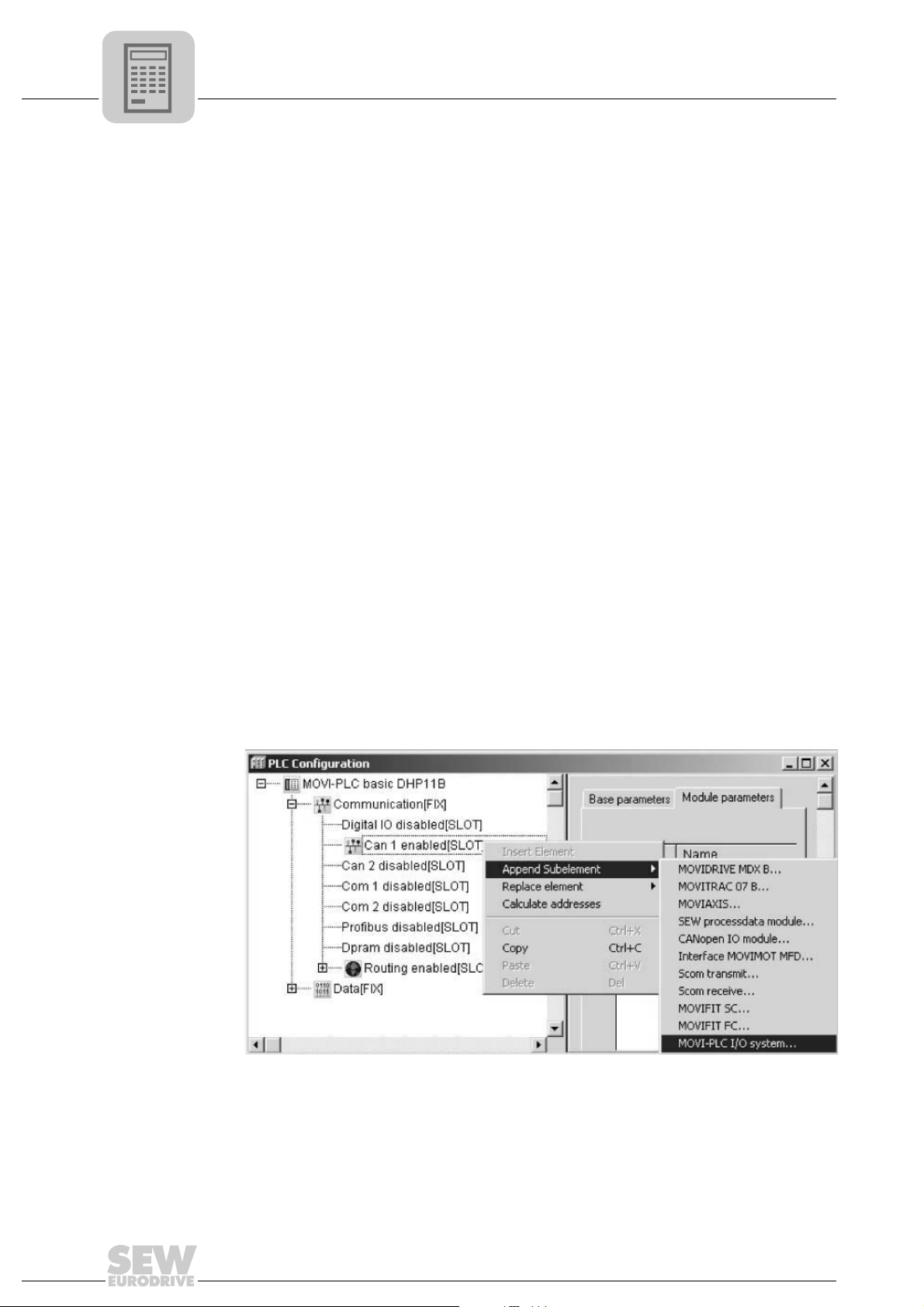
5
Project Planning with MOVITOOLS® MotionStudio
PLC Editor project planning tool
5 Project Planning with MOVITOOLS® MotionStudio
This chapter describes the project planning for the MOVI-PLC® I/O system with the
MOVITOOLS
®
MotionStudio.
5.1 PLC Editor project planning tool
• Start MOVITOOLS® MotionStudio and the PLC Editor.
You find more detailed information in the "Project Planning with MOVITOOLS
MotionStudio" section in the manuals "MOVI-PLC® basic controller DHP11B" and
MOVI-PLC
• For basic information on the PLC Editor and PLC configuration, refer to the "MOVIPLC
®
advanced controller DH.41B"
®
Programming in the PLC Editor" system manual.
5.2 Adding a MOVI-PLC® I/O system
• In the PLC configuration, activate the interface to be used for connecting the
OCC11B CAN bus coupler of the MOVI-PLC
controller. Replace the relevant entry with "... enabled" (e.g. "CAN 1 enabled" →
following figure)
The baud rate set in the module parameters of the interface must correspond with
the baud rate set on the OCC1B CAN bus coupler (→ section "OCC11B CAN bus
coupler").
• Select the required entry (e.g. "CAN 1 enabled") and choose the menu items
[Append Subelement] / [MOVI-PLC I/O system] from the context menu (→ following
figure).
• In the module parameters of the MOVI-PLC
that was set at the CAN bus coupler of the MOVI-PLC
"OCC11B CAN bus coupler").
®
I/O system to the MOVI-PLC
®
I/O system, set the same bus address
®
I/O system (→ section
®
®
64
11675AEN
Manual – MOVI-PLC® I/O System
Page 65
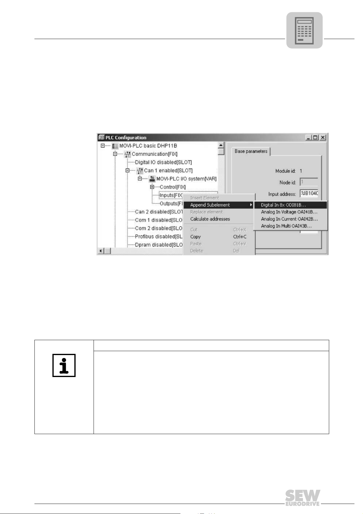
Project Planning with MOVITOOLS® MotionStudio
5.3 Configuring I/O modules
Configuring I/O modules
5
• In the PLC configuration (→ following figure), the entries "Inputs" and "Outputs"
appear underneath the MOVI-P LC
®
PLC
I/O system to these entries. To do so, choose the required module designa-
tions from the context menu.
• Choosing an "Analog ... OA.." analog module will add the relevant module. Choosing
the entry "Digital ... 8x OD.." will guide you in one step to the configuration of 8 digital
modules even if less than 8 modules are installed.
®
I/O system. Add the I/O modules of your MOVI-
11676AEN
In the event of multiple configuration of I/O modules of the same type, the sequence
displayed in the PLC configuration window will correspond with the physical
sequence in the MOVI-PLC
arrangement and combination of various I/O module types need not be reflected in
the PLC configuration. Terminal modules are not displayed in the PLC configuration.
Example: The physical arrangement of the MOVI-PLC
ODI81B digital input modules followed by one ODO81B digital output module and
five ODI81B digital input modules. However, the PLC configuration still displays all 8
digital input modules in the "Digital IN 8x ODI81B.." entry.
®
I/O system from left to right. However, the physical
®
I/O system consists of three
NOTES
• The following scaling applies in conjunction with a MOVI-PLC® basic DHP11B
controller:
– You can arrange a maximum of one analog input module and one analog output
module each to the bus coupler per MOVI-PLC
– Additonally, you can install a maximum number of 8 digital input modules and 8
digital output modules and terminal modules.
Configurations other than this scaling (e.g. two entries "Digital 8x ODI81B..") are not
supported physically.
• Please also refer to the information in the "Backplane bus" and "step-by-step
installation of the I/O system" section in the "Mechanical Installation" chapter.
®
I/O system.
Manual – MOVI-PLC® I/O System
65
Page 66
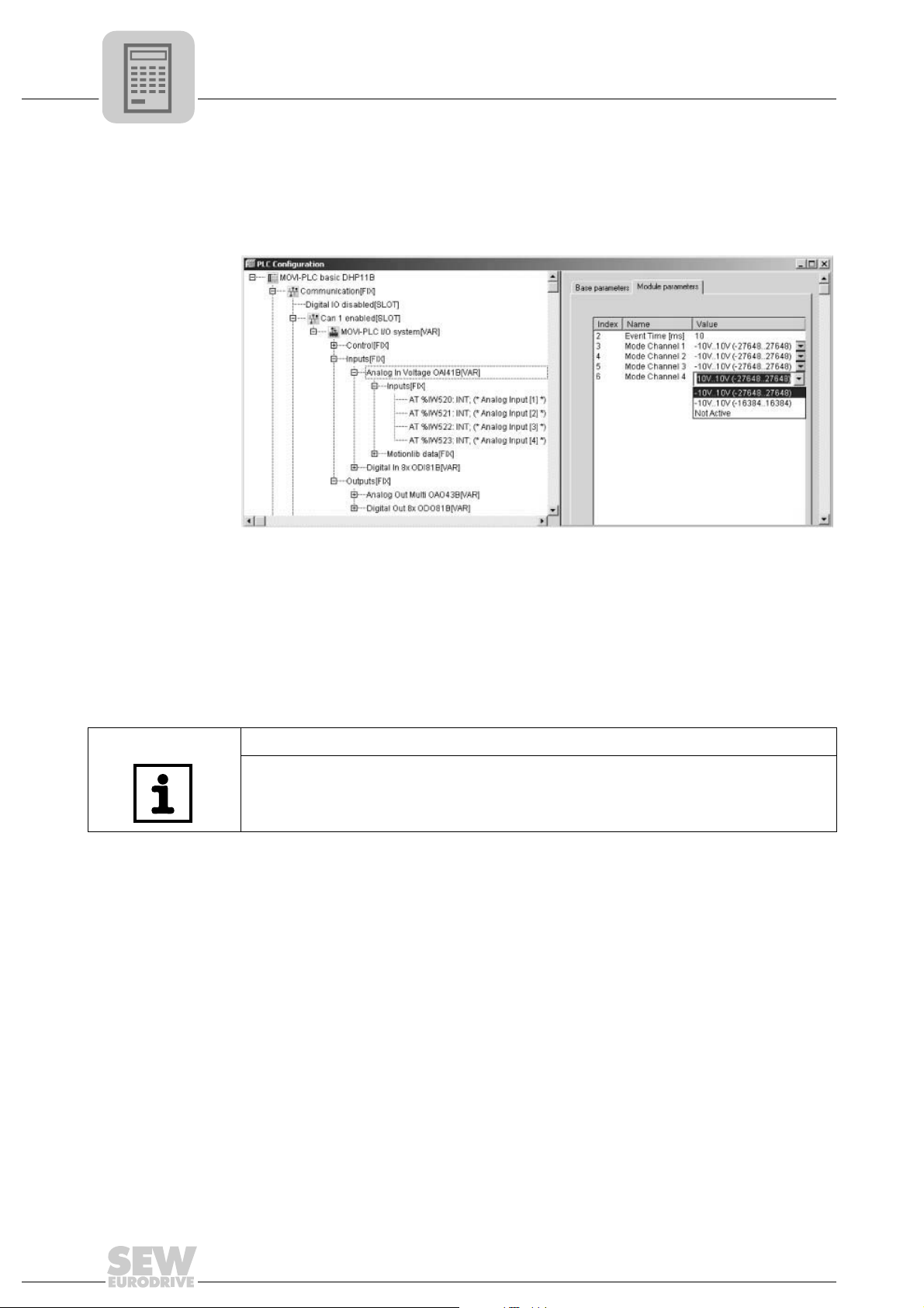
5
Project Planning with MOVITOOLS® MotionStudio
Configuring I/O modules
5.4 Configuring I/O modules
In the module parameters of the I/O modules (→ following figure), set the required
functionality according to the module descriptions (→ section "Unit design and technical
data of I/O modules").
5.5 IEC program
• In the library manager, add the MPLCUtilities library to your project. Have the
• The process image of the relevant I/O system is refreshed while the function module
11677AEN
MPLC_ConnectSEWIOSystem_CAN function module execute an instance in a
cyclic task per MOVI-PLC
is being executed.
®
I/O system.
NOTE
For a detailed description of the MPLC_ConnectSEWIOSystem_CAN function module
and the output diagnostic information, refer to the "MPLCUtilities Library for MOVI-
®
PLC
" manual.
66
Manual – MOVI-PLC® I/O System
Page 67
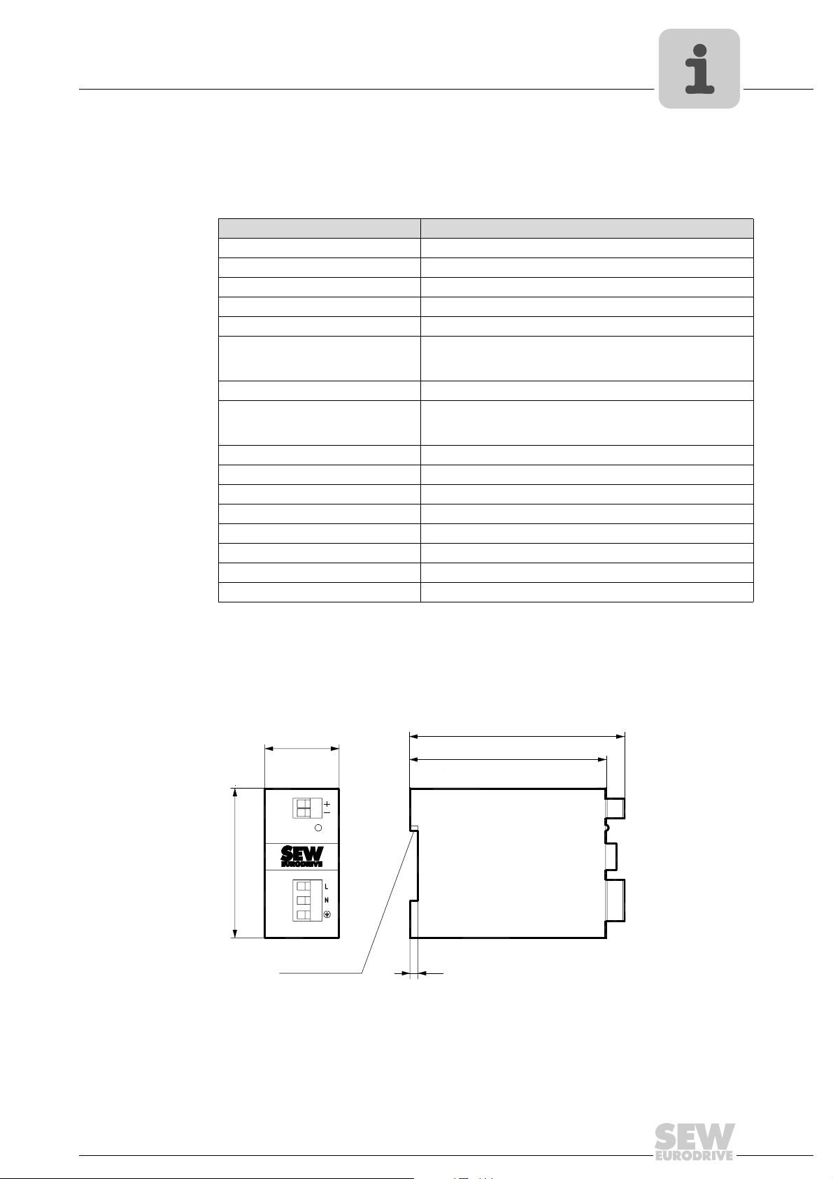
UWU52A switched-mode power supply
6 Appendix
6.1 UWU52A switched-mode power supply
Technical data
Switched-mode power supply UWU52A
Part number 188 181 7
Input voltage AC 1 × 110 ... 240 V
Voltage range AC 95 ... 265 V, AC 110 ... 300 V
Frequency 50/60 Hz
Max. no-load current AC 40 mA
Rated input current
at AC 1 × 110 V
at AC 1 × 230 V
Output voltage DC 24 V (-1% / +3%)
Rated output current
at 40 °C
at 55 °C
Residual ripple < 50 mV
Interference voltage < 120 mV
Power loss < 5.5 W
Weight 0.23 kg
Operating temperature 0 ... +55 °C (condensation not permitted)
Degree of protection IP20 (EN 60529)
Protection class I
Connection Screw terminals for cable cross sections 0.20 ... 2.5 mm
Appendix
1.04 AAC
AC 0.63 A
DC 2.5 A
DC 2.0 A
eff
SS
6
2
Dimension drawing
The power supply is short-circuit proof and protected against overload. Input and output
are galvanically isolated.
38
76
4EN 60715TM35
109
101
62140AXX
Leave a clearance of at least 50mm at top and bottom of venting slots!
Manual – MOVI-PLC® I/O System
67
Page 68

7
7Index
Index
A
Appendix
B
Backplane bus connector
C
CANopen bus coupler OCC11B
D
Dimension drawing mounting rail
E
Electrical installation
EMC-compliant installation
Exclusion of liability
G
General information
General notes
I
Important notes
Installation
Installation clearance
M
Mechanical installation
Mounting position
.............................................................67
UWU52A switched-mode power supply
....................................11
.........................18
CAN bus plug connector assignment
Description
Diagnostics LED
Part number
Setting the baud rate using the address
adjuster
Setting the module ID
Technical data
Voltage supply
...................................................18
...........................................18
..................................................18
.........................................................20
...................................21
..............................................21
..............................................20
..........................9
...........................................15
EMC-compliant installation
Procedure for wiring plug connectors
Shielding of lines
Wiring plug connectors
..........................................15
...........................15
.................................16
.................................15
...............................................4
..............................................4
Exclusion of liability
General safety notes for bus systems
Rights to claim under limited warranty
Structure of the safety notes
Hoist applications
Electrical installation
Mechanical installation
........................................4
..........................4
...........................................5
.....................................15
...................................9
..........................................11
Backplane bus connector
Dimension drawing mounting rail
Installation clearance
Mounting position
Notes on installation of I/O modules
Step-by-step installation of the I/O system
Step-by-step removal of the I/O system
.........................................10
.............................11
....................................11
................................................10
.......67
...........19
...........17
............5
...........4
...................9
...............9
...13
.......14
®
MOVI-PLC
Scope of delivery
O
OAI41B analog input module (current)
Technical data
OAI41B analog input module (voltage)
'SF' LED
Connector assignment
Description
Function assignment
Part number
Technical data
Wiring diagram
OAI42B analog input module (current)
'SF' LED
Connector assignment
Description
Function assignment
Part number
Wiring diagram
OAI43B analog input module (multi-input)
Connector assignment
Description
Function assignment
LED F0 ... F3
Part number
Technical data
Wiring diagram
OAO41B analog output module (voltage)
Connector assignment
Description
Function assignment
LED +
Part number
Technical data
Wiring diagram
OAO42B analog output module (current)
Connector assignment
Description
Function assignment
LED +
Part number
Technical data
Wiring diagram
OAO43B analog output module (multi-output)
Connector assignment
Description
Function assignment
Part number
SF LED
Technical data
Wiring diagram
ODI81B digital input module
Connector assignment
I/O system ....................................... 6
........................................... 7
............................................. 36
.............. 30
....................................................... 31
................................. 31
................................................... 30
................................... 32
................................................. 30
............................................. 32
............................................ 31
.............. 34
....................................................... 35
................................. 35
................................................... 34
................................... 36
................................................. 34
............................................ 35
......... 38
................................. 38
................................................... 38
................................... 40
............................................... 39
................................................. 38
............................................. 46
............................................ 39
.......... 49
................................. 50
................................................... 49
................................... 51
........................................................... 50
................................................. 49
............................................. 52
............................................ 50
.......... 54
................................. 55
................................................... 54
................................... 56
........................................................... 55
................................................. 54
............................................. 56
............................................ 55
................................. 59
................................................... 58
................................... 60
................................................. 58
........................................................ 59
............................................. 62
............................................ 59
.............................. 24
................................. 24
... 58
68
Manual – MOVI-PLC® I/O System
Page 69

Description ...................................................24
LED status indicator
LED wiring diagram
Part number
Technical data LED
ODO81B digital output module
'F' LED
Connector assignment
Description
LED +
LED 0 ... 7
Part number
Technical data
Wiring diagram
Other applicable documentation
P
Procedure for wiring plug connectors
Project planning tool PLC Editor
Project Planning with MOVITOOLS
MotionStudio
Project planning with MOVITOOLS
Adding a MOVI-PLC
Configuring I/O modules
IEC program
Project planning tool PLC Editor
..................................................24
..........................................................28
...................................................27
...........................................................28
....................................................28
..................................................27
.................................................64
.................................................66
.....................................25
......................................25
......................................25
...........................27
.................................27
..............................................28
.............................................28
...........................5
.................17
.........................64
®
®
®
I/O system .................64
MotionStudio
........................ 65, 66
..................64
Index
7
R
Rights to claim under limited warranty
S
Safety notes
Structure of the safety notes
Shielding of lines
Step-by-step installation of the I/O system
Step-by-step removal of the I/O system ..............14
System description
MOVI-PLC
T
Terminal module OTM12B
Technical data
U
Unit design and technical data of the
MOVI-PLC
UWU52A switched-mode power supply
Dimension drawing
Technical data
.................................................15
®
I/O system ..................................6
..................................22
..............................................23
®
I/O system ................................18
.......................................67
..............................................67
..................4
..........................4
.........13
W
Wiring plug connectors
Manual – MOVI-PLC® I/O System
.......................................16
69
Page 70
Address List
Address List
Germany
Headquarters
Production
Sales
Service
Competence Center
Bruchsal SEW-EURODRIVE GmbH & Co KG
Ernst-Blickle-Straße 42
D-76646 Bruchsal
P.O . Bo x
Postfach 3023 • D-76642 Bruchsal
Central SEW-EURODRIVE GmbH & Co KG
Ernst-Blickle-Straße 1
D-76676 Graben-Neudorf
North SEW-EURODRIVE GmbH & Co KG
Alte Ricklinger Straße 40-42
D-30823 Garbsen (near Hannover)
East SEW-EURODRIVE GmbH & Co KG
Dänkritzer Weg 1
D-08393 Meerane (near Zwickau)
South SEW-EURODRIVE GmbH & Co KG
Domagkstraße 5
D-85551 Kirchheim (near München)
West SEW-EURODRIVE GmbH & Co KG
Siemensstraße 1
D-40764 Langenfeld (near Düsseldorf)
Electronics SEW-EURODRIVE GmbH & Co KG
Ernst-Blickle-Straße 42
D-76646 Bruchsal
Drive Service Hotline / 24 Hour Service +49 180 5 SEWHELP
Additional addresses for service in Germany provided on request!
Tel. +49 7251 75-0
Fax +49 7251 75-1970
http://www.sew-eurodrive.de
[email protected]
Tel. +49 7251 75-1710
Fax +49 7251 75-1711
[email protected]
Tel. +49 5137 8798-30
Fax +49 5137 8798-55
[email protected]
Tel. +49 3764 7606-0
Fax +49 3764 7606-30
[email protected]
Tel. +49 89 909552-10
Fax +49 89 909552-50
[email protected]
Tel. +49 2173 8507-30
Fax +49 2173 8507-55
[email protected]
Tel. +49 7251 75-1780
Fax +49 7251 75-1769
[email protected]
+49 180 5 7394357
France
Production
Sales
Service
Production Forbach SEW-EUROCOME
Assembly
Sales
Service
Algeria
Sales Alger Réducom
Haguenau SEW-USOCOME
48-54, route de Soufflenheim
B. P. 20185
F-67506 Haguenau Cedex
Zone Industrielle
Technopôle Forbach Sud
B. P. 30269
F-57604 Forbach Cedex
Bordeaux SEW-USOCOME
Parc d'activités de Magellan
62, avenue de Magellan - B. P. 182
F-33607 Pessac Cedex
Lyon SEW-USOCOME
Parc d'Affaires Roosevelt
Rue Jacques Tati
F-69120 Vaulx en Velin
Paris SEW-USOCOME
Zone industrielle
2, rue Denis Papin
F-77390 Verneuil I'Etang
Additional addresses for service in France provided on request!
16, rue des Frères Zaghnoun
Bellevue El-Harrach
16200 Alger
Tel. +33 3 88 73 67 00
Fax +33 3 88 73 66 00
http://www.usocome.com
[email protected]
Tel. +33 3 87 29 38 00
Tel. +33 5 57 26 39 00
Fax +33 5 57 26 39 09
Tel. +33 4 72 15 37 00
Fax +33 4 72 15 37 15
Tel. +33 1 64 42 40 80
Fax +33 1 64 42 40 88
Tel. +213 21 8222-84
Fax +213 21 8222-84
70
Argentina
Assembly
Sales
Service
Buenos Aires SEW EURODRIVE ARGENTINA S.A.
Centro Industrial Garin, Lote 35
Ruta Panamericana Km 37,5
1619 Garin
Tel. +54 3327 4572-84
Fax +54 3327 4572-21
[email protected]
Page 71
Australia
Assembly
Sales
Service
Austria
Assembly
Sales
Service
Belarus
Sales Minsk SEW-EURODRIVE BY
Melbourne SEW-EURODRIVE PTY. LTD.
27 Beverage Drive
Tullamarine, Victoria 3043
Sydney SEW-EURODRIVE PTY. LTD.
9, Sleigh Place, Wetherill Park
New South Wales, 2164
Townsville SEW-EURODRIVE PTY. LTD.
12 Leyland Street
Garbutt, QLD 4814
Wien SEW-EURODRIVE Ges.m.b.H.
Richard-Strauss-Strasse 24
A-1230 Wien
RybalkoStr. 26
BY-220033 Minsk
Address List
Tel. +61 3 9933-1000
Fax +61 3 9933-1003
http://www.sew-eurodrive.com.au
[email protected]
Tel. +61 2 9725-9900
Fax +61 2 9725-9905
[email protected]
Tel. +61 7 4779 4333
Fax +61 7 4779 5333
[email protected]
Tel. +43 1 617 55 00-0
Fax +43 1 617 55 00-30
http://sew-eurodrive.at
[email protected]
Tel.+375 (17) 298 38 50
Fax +375 (17) 29838 50
[email protected]
Belgium
Assembly
Sales
Service
Brazil
Production
Sales
Service
Bulgaria
Sales Sofia BEVER-DRIVE GmbH
Cameroon
Sales Douala Electro-Services
Canada
Assembly
Sales
Service
Brüssel SEW Caron-Vector S.A.
Avenue Eiffel 5
B-1300 Wavre
Sao Paulo SEW-EURODRIVE Brasil Ltda.
Avenida Amâncio Gaiolli, 50
Caixa Postal: 201-07111-970
Guarulhos/SP - Cep.: 07251-250
Additional addresses for service in Brazil provided on request!
Bogdanovetz Str.1
BG-1606 Sofia
Rue Drouot Akwa
B.P. 2024
Douala
Tor onto SEW-EURODRIVE CO. OF CANADA LTD.
210 Walker Drive
Bramalea, Ontario L6T3W1
Vancouver SEW-EURODRIVE CO. OF CANADA LTD.
7188 Honeyman Street
Delta. B.C. V4G 1 E2
Montreal SEW-EURODRIVE CO. OF CANADA LTD.
2555 Rue Leger
LaSalle, Quebec H8N 2V9
Additional addresses for service in Canada provided on request!
Tel. +32 10 231-311
Fax +32 10 231-336
http://www.sew-eurodrive.be
[email protected]
Tel. +55 11 6489-9133
Fax +55 11 6480-3328
http://www.sew.com.br
[email protected]
Tel. +359 2 9151160
Fax +359 2 9151166
[email protected]
Tel. +237 33 431137
Fax +237 33 431137
Tel. +1 905 791-1553
Fax +1 905 791-2999
http://www.sew-eurodrive.ca
[email protected]
Tel. +1 604 946-5535
Fax +1 604 946-2513
[email protected]
Tel. +1 514 367-1124
Fax +1 514 367-3677
[email protected]
71
Page 72
Chile
Assembly
Sales
Service
China
Production
Assembly
Sales
Service
Assembly
Sales
Service
Colombia
Assembly
Sales
Service
Address List
Santiago de
Chile
Tianjin SEW-EURODRIVE (Tianjin) Co., Ltd.
Suzhou SEW-EURODRIVE (Suzhou) Co., Ltd.
Additional addresses for service in China provided on request!
Bogotá SEW-EURODRIVE COLOMBIA LTDA.
SEW-EURODRIVE CHILE LTDA.
Las Encinas 1295
Parque Industrial Valle Grande
LAMPA
RCH-Santiago de Chile
P.O . Bo x
Casilla 23 Correo Quilicura - Santiago - Chile
No. 78, 13th Avenue, TEDA
Tianjin 300457
333, Suhong Middle Road
Suzhou Industrial Park
Jiangsu Province, 215021
P. R . Ch in a
Calle 22 No. 132-60
Bodega 6, Manzana B
Santafé de Bogotá
Tel. +56 2 75770-00
Fax +56 2 75770-01
http://www.sew-eurodrive.cl
[email protected]
Tel. +86 22 25322612
Fax +86 22 25322611
[email protected]
http://www.sew-eurodrive.com.cn
Tel. +86 512 62581781
Fax +86 512 62581783
[email protected]
Tel. +57 1 54750-50
Fax +57 1 54750-44
http://www.sew-eurodrive.com.co
[email protected]
Croatia
Sales
Service
Czech Republic
Sales Praha SEW-EURODRIVE CZ S.R.O.
Denmark
Assembly
Sales
Service
Estonia
Sales Tallin ALAS-KUUL AS
Finland
Assembly
Sales
Service
Gabon
Sales Libreville Electro-Services
Zagreb KOMPEKS d. o. o.
PIT Erdödy 4 II
HR 10 000 Zagreb
Business Centrum Praha
Lužná 591
CZ-16000 Praha 6 - Vokovice
Kopenhagen SEW-EURODRIVEA/S
Geminivej 28-30
DK-2670 Greve
Reti tee 4
EE-75301 Peetri küla, Rae vald, Harjumaa
Lahti SEW-EURODRIVE OY
Vesimäentie 4
FIN-15860 Hollola 2
B.P. 1889
Libreville
Tel. +385 1 4613-158
Fax +385 1 4613-158
[email protected]
Tel. +420 220121234
Fax +420 220121237
http://www.sew-eurodrive.cz
[email protected]
Tel. +45 43 9585-00
Fax +45 43 9585-09
http://www.sew-eurodrive.dk
[email protected]
Tel. +372 6593230
Fax +372 6593231
[email protected]
Tel. +358 201 589-300
Fax +358 3 780-6211
[email protected]
http://www.sew-eurodrive.fi
Tel. +241 7340-11
Fax +241 7340-12
72
Great Britain
Assembly
Sales
Service
Normanton SEW-EURODRIVE Ltd.
Beckbridge Industrial Estate
P.O. Box No.1
GB-Normanton, West- Yorkshire WF6 1QR
Tel. +44 1924 893-855
Fax +44 1924 893-702
http://www.sew-eurodrive.co.uk
[email protected]
Page 73
Greece
Sales
Service
Hong Kong
Assembly
Sales
Service
Hungary
Sales
Service
India
Assembly
Sales
Service
Technical Offices Bangalore SEW-EURODRIVE India Private Limited
Athen Christ. Boznos & Son S.A.
12, Mavromichali Street
P.O. Box 80136, GR-18545 Piraeus
Hong Kong SEW-EURODRIVE LTD.
Unit No. 801-806, 8th Floor
Hong Leong Industrial Complex
No. 4, Wang Kwong Road
Kowloon, Hong Kong
Budapest SEW-EURODRIVE Kft.
H-1037 Budapest
Kunigunda u. 18
Baroda SEW-EURODRIVE India Pvt. Ltd.
Plot No. 4, Gidc
Por Ramangamdi • Baroda - 391 243
Gujarat
308, Prestige Centre Point
7, Edward Road
Bangalore
Address List
Tel. +30 2 1042 251-34
Fax +30 2 1042 251-59
http://www.boznos.gr
[email protected]
Tel. +852 2 7960477 + 79604654
Fax +852 2 7959129
[email protected]
Tel. +36 1 437 06-58
Fax +36 1 437 06-50
[email protected]
Tel. +91 265 2831086
Fax +91 265 2831087
http://www.seweurodriveindia.com
[email protected]
Tel. +91 80 22266565
Fax +91 80 22266569
[email protected]
Ireland
Sales
Service
Israel
Sales Tel-Aviv Liraz Handasa Ltd.
Italy
Assembly
Sales
Service
Ivory Coast
Sales Abidjan SICA
Japan
Assembly
Sales
Service
Dublin Alperton Engineering Ltd.
48 Moyle Road
Dublin Industrial Estate
Glasnevin, Dublin 11
Ahofer Str 34B / 228
58858 Holon
Milano SEW-EURODRIVE di R. Blickle & Co.s.a.s.
Via Bernini,14
I-20020 Solaro (Milano)
Ste industrielle et commerciale pour l'Afrique
165, Bld de Marseille
B.P. 2323, Abidjan 08
Iwata SEW-EURODRIVE JAPAN CO., LTD
250-1, Shimoman-no,
Iwata
Shizuoka 438-0818
Tel. +353 1 830-6277
Fax +353 1 830-6458
[email protected]
Tel. +972 3 5599511
Fax +972 3 5599512
[email protected]
Tel. +39 02 96 9801
Fax +39 02 96 799781
http://www.sew-eurodrive.it
[email protected]
Tel. +225 2579-44
Fax +225 2584-36
Tel. +81 538 373811
Fax +81 538 373814
http://www.sew-eurodrive.co.jp
[email protected]
Korea
Assembly
Sales
Service
Ansan-City SEW-EURODRIVE KOREA CO., LTD.
B 601-4, Banweol Industrial Estate
1048-4, Shingil-Dong
Ansan 425-120
Tel. +82 31 492-8051
Fax +82 31 492-8056
http://www.sew-korea.co.kr
[email protected]
73
Page 74
Address List
Latvia
Sales Riga SIA Alas-Kuul
Lebanon
Sales Beirut Gabriel Acar & Fils sarl
Lithuania
Sales Alytus UAB Irseva
Luxembourg
Assembly
Sales
Service
Brüssel CARON-VECTOR S.A.
Katlakalna 11C
LV-1073 Riga
B. P. 80484
Bourj Hammoud, Beirut
Naujoji 19
LT-62175 Alytus
Avenue Eiffel 5
B-1300 Wavre
Tel. +371 7139253
Fax +371 7139386
http://www.alas-kuul.com
[email protected]
Tel. +961 1 4947-86
+961 1 4982-72
+961 3 2745-39
Fax +961 1 4949-71
[email protected]
Tel. +370 315 79204
Fax +370 315 56175
[email protected]
http://www.sew-eurodrive.lt
Tel. +32 10 231-311
Fax +32 10 231-336
http://www.sew-eurodrive.lu
[email protected]
Malaysia
Assembly
Sales
Service
Mexico
Assembly
Sales
Service
Morocco
Sales Casablanca Afit
Netherlands
Assembly
Sales
Service
New Zealand
Assembly
Sales
Service
Johore SEW-EURODRIVE SDN BHD
No. 95, Jalan Seroja 39, Taman Johor Jaya
81000 Johor Bahru, Johor
West Malaysia
Queretaro SEW-EURODRIVE MEXIKO SA DE CV
SEM-981118-M93
Tequisquiapan No. 102
Parque Industrial Queretaro
C.P. 76220
Queretaro, Mexico
5, rue Emir Abdelkader
MA 20300 Casablanca
Rotterdam VECTOR Aandrijftechniek B.V.
Industrieweg 175
NL-3044 AS Rotterdam
Postbus 10085
NL-3004 AB Rotterdam
Auckland SEW-EURODRIVE NEW ZEALAND LTD.
P.O. Box 58-428
82 Greenmount drive
East Tamaki Auckland
Christchurch SEW-EURODRIVE NEW ZEALAND LTD.
10 Settlers Crescent, Ferrymead
Christchurch
Tel. +60 7 3549409
Fax +60 7 3541404
[email protected]
Tel. +52 442 1030-300
Fax +52 442 1030-301
http://www.sew-eurodrive.com.mx
[email protected]
Tel. +212 22618372
Fax +212 22618351
[email protected]
Tel. +31 10 4463-700
Fax +31 10 4155-552
http://www.vector.nu
[email protected]
Tel. +64 9 2745627
Fax +64 9 2740165
http://www.sew-eurodrive.co.nz
[email protected]
Tel. +64 3 384-6251
Fax +64 3 384-6455
[email protected]
74
Norway
Assembly
Sales
Service
Moss SEW-EURODRIVE A/S
Solgaard skog 71
N-1599 Moss
Tel. +47 69 241-020
Fax +47 69 241-040
http://www.sew-eurodrive.no
[email protected]
Page 75
Peru
Assembly
Sales
Service
Poland
Assembly
Sales
Service
Portugal
Assembly
Sales
Service
Romania
Sales
Service
Lima SEW DEL PERU MOTORES REDUCTORES
S.A.C.
Los Calderos, 120-124
Urbanizacion Industrial Vulcano, ATE, Lima
Lodz SEW-EURODRIVE Polska Sp.z.o.o.
ul. Techniczna 5
PL-92-518 Łódź
Coimbra SEW-EURODRIVE, LDA.
Apartado 15
P-3050-901 Mealhada
Bucureşti Sialco Trading SRL
str. Madrid nr.4
011785 Bucuresti
Address List
Tel. +51 1 3495280
Fax +51 1 3493002
http://www.sew-eurodrive.com.pe
[email protected]
Tel. +48 42 67710-90
Fax +48 42 67710-99
http://www.sew-eurodrive.pl
[email protected]
Tel. +351 231 20 9670
Fax +351 231 20 3685
http://www.sew-eurodrive.pt
[email protected]
Tel. +40 21 230-1328
Fax +40 21 230-7170
[email protected]
Russia
Assembly
Sales
Service
Senegal
Sales Dakar SENEMECA
Serbia
Sales Beograd DIPAR d.o.o.
Singapore
Assembly
Sales
Service
Slovakia
Sales Bratislava SEW-Eurodrive SK s.r.o.
St. Petersburg ZAO SEW-EURODRIVE
P.O . Bo x 3 6
195220 St. Petersburg Russia
Mécanique Générale
Km 8, Route de Rufisque
B.P. 3251, Dakar
Ustanicka 128a
PC Košum, IV floor
SCG-11000 Beograd
Singapore SEW-EURODRIVE PTE. LTD.
No 9, Tuas Drive 2
Jurong Industrial Estate
Singapore 638644
Rybničná 40
SK-83554 Bratislava
Žilina SEW-Eurodrive SK s.r.o.
ul. Vojtecha Spanyola 33
SK-010 01 Žilina
Banská Bystrica SEW-Eurodrive SK s.r.o.
Rudlovská cesta 85
SK-97411 Banská Bystrica
Tel. +7 812 3332522 +7 812 5357142
Fax +7 812 3332523
http://www.sew-eurodrive.ru
[email protected]
Tel. +221 849 47-70
Fax +221 849 47-71
[email protected]
Tel. +381 11 347 3244 / +381 11 288
0393
Fax +381 11 347 1337
[email protected]
Tel. +65 68621701
Fax +65 68612827
http://www.sew-eurodrive.com.sg
[email protected]
Tel. +421 2 49595201
Fax +421 2 49595200
[email protected]
http://sk.sew-eurodrive.com
Tel. +421 41 700 2513
Fax +421 41 700 2514
[email protected]
Tel. +421 48 414 6564
Fax +421 48 414 6566
[email protected]
Slovenia
Sales
Service
Celje Pakman - Pogonska Tehnika d.o.o.
UI. XIV. divizije 14
SLO - 3000 Celje
Tel. +386 3 490 83-20
Fax +386 3 490 83-21
[email protected]
75
Page 76
South Africa
Assembly
Sales
Service
Spain
Assembly
Sales
Service
Address List
Johannesburg SEW-EURODRIVE (PROPRIETARY) LIMITED
Eurodrive House
Cnr. Adcock Ingram and Aerodrome Roads
Aeroton Ext. 2
Johannesburg 2013
P.O.Box 90004
Bertsham 2013
Capetown SEW-EURODRIVE (PROPRIETARY) LIMITED
Rainbow Park
Cnr. Racecourse & Omuramba Road
Montague Gardens
Cape Town
P.O.Box 36556
Chempet 7442
Cape Town
Durban SEW-EURODRIVE (PROPRIETARY) LIMITED
2 Monaceo Place
Pinetown
Durban
P.O. Box 10433, Ashwood 3605
Bilbao SEW-EURODRIVE ESPAÑA, S.L.
Parque Tecnológico, Edificio, 302
E-48170 Zamudio (Vizcaya)
Tel. +27 11 248-7000
Fax +27 11 494-3104
http://www.sew.co.za
[email protected]
Tel. +27 21 552-9820
Fax +27 21 552-9830
Telex 576 062
[email protected]
Tel. +27 31 700-3451
Fax +27 31 700-3847
[email protected]
Tel. +34 94 43184-70
Fax +34 94 43184-71
http://www.sew-eurodrive.es
[email protected]
Sweden
Assembly
Sales
Service
Switzerland
Assembly
Sales
Service
Thailand
Assembly
Sales
Service
Tun isi a
Sales Tunis T. M.S. Technic Marketing Service
Turkey
Assembly
Sales
Service
Jönköping SEW-EURODRIVE AB
Gnejsvägen 6-8
S-55303 Jönköping
Box 3100 S-55003 Jönköping
Basel Alfred lmhof A.G.
Jurastrasse 10
CH-4142 Münchenstein bei Basel
Chonburi SEW-EURODRIVE (Thailand) Ltd.
700/456, Moo.7, Donhuaroh
Muang
Chonburi 20000
5, Rue El Houdaibiah
1000 Tunis
Istanbul SEW-EURODRIVE
Hareket Sistemleri San. ve Tic. Ltd. Sti.
Bagdat Cad. Koruma Cikmazi No. 3
TR-34846 Maltepe ISTANBUL
Tel. +46 36 3442-00
Fax +46 36 3442-80
http://www.sew-eurodrive.se
[email protected]
Tel. +41 61 417 1717
Fax +41 61 417 1700
http://www.imhof-sew.ch
[email protected]
Tel. +66 38 454281
Fax +66 38 454288
[email protected]
Tel. +216 71 4340-64 + 71 4320-29
Fax +216 71 4329-76
[email protected]
Tel. +90 216 4419163 / 164 3838014/15
Fax +90 216 3055867
http://www.sew-eurodrive.com.tr
[email protected]
76
Ukraine
Sales
Service
Sales Kiev SEW-EURODRIVE GmbH
Dnepropetrovsk SEW-EURODRIVE
Str. Rabochaja 23-B, Office 409
49008 Dnepropetrovsk
S. Oleynika str. 21
02068 Kiev
Tel. +380 56 370 3211
Fax +380 56 372 2078
http://www.sew-eurodrive.ua
[email protected]
Tel. +380 44 503 95 77
Fax +380 44 503 95 78
[email protected]
Page 77
USA
Production
Assembly
Sales
Service
Assembly
Sales
Service
Greenville SEW-EURODRIVE INC.
1295 Old Spartanburg Highway
P.O . Bo x 5 18
Lyman, S.C. 29365
San Francisco SEW-EURODRIVE INC.
30599 San Antonio St.
Hayward, California 94544-7101
Philadelphia/PA SEW-EURODRIVE INC.
Pureland Ind. Complex
2107 High Hill Road, P.O. Box 481
Bridgeport, New Jersey 08014
Dayton SEW-EURODRIVE INC.
2001 West Main Street
Troy, Ohio 45373
Dallas SEW-EURODRIVE INC.
3950 Platinum Way
Dallas, Texas 75237
Additional addresses for service in the USA provided on request!
Address List
Tel. +1 864 439-7537
Fax Sales +1 864 439-7830
Fax Manuf. +1 864 439-9948
Fax Ass. +1 864 439-0566
Telex 805 550
http://www.seweurodrive.com
[email protected]
Tel. +1 510 487-3560
Fax +1 510 487-6381
[email protected]
Tel. +1 856 467-2277
Fax +1 856 845-3179
[email protected]
Tel. +1 937 335-0036
Fax +1 937 440-3799
[email protected]
Tel. +1 214 330-4824
Fax +1 214 330-4724
[email protected]
Venezuela
Assembly
Sales
Service
Valencia SEW-EURODRIVE Venezuela S.A.
Av. Norte Sur No. 3, Galpon 84-319
Zona Industrial Municipal Norte
Valencia, Estado Carabobo
Tel. +58 241 832-9804
Fax +58 241 838-6275
http://www.sew-eurodrive.com.ve
[email protected]
[email protected]
77
Page 78

Page 79

SEW-EURODRIVE – Driving the world
Page 80

Gearmotors \ Industrial Gear Units \ Drive Electronics \ Drive Automation \ Services
How we’re driving the world
With people who
think fast and
develop the
future with you.
With a global presence
that offers responsive
and reliable solutions.
Anywhere.
With a worldwide
service network that is
always close at hand.
With drives and controls
that automatically
improve your productivity.
With innovative
technology that solves
tomorrow’s problems
today.
With comprehensive
knowledge in virtually
every branch of
industry today.
With online information
and software updates,
via the Internet, available
around the clock.
With uncompromising
quality that reduces the
cost and complexity of
daily operations.
SEW-EURODRIVE
Driving the world
SEW-EURODRIVE GmbH & Co KG
P.O. Box 3023 · D-76642 Bruchsal / Germany
Phone +49 7251 75-0 · Fax +49 7251 75-1970
[email protected]
www.sew-eurodrive.com
 Loading...