

SEW movigear sni-b Operating Instructions Manual
Drive Technology \ Drive Automation \ System Integration \ Services
Operating Instructions
Mechatronic Drive System
MOVIGEAR
®
SNI-B
Single Line Network Installation
Edition 12/2013 20254547 / EN
SEW-EURODRIVE—Driving the world

Contents
Contents
1 General information ............................................................................................ 6
1.1 How to use this documentation................................................................... 6
1.2 Structure of the safety notes ....................................................................... 6
1.3 Rights to claim under warranty ................................................................... 7
1.4 Exclusion of liability..................................................................................... 7
1.5 Copyright..................................................................................................... 7
1.6 Product names and trademarks.................................................................. 7
2 Safety notes......................................................................................................... 8
2.1 General information .................................................................................... 8
2.2 Target group ............................................................................................... 8
2.3 Designated use ........................................................................................... 9
2.4 Transportation, storage ............................................................................ 9
2.5 Installation................................................................................................. 10
2.6 Electrical connection ................................................................................. 10
2.7 Safe disconnection.................................................................................... 10
2.8 Operation .............................................................................................. 11
3 Unit structure..................................................................................................... 12
3.1 MOVIGEAR
3.2 Shaft types .............................................................................................. 13
3.3 Housing mounting ................................................................................... 14
3.4 Cable entry positions ............................................................................. 15
3.5 Example nameplate and type designation of the drive unit ................... 16
3.6 Electronics ............................................................................................ 17
3.7 Application options .............................................................................. 19
3.8 Example nameplate and type designation of electronics ...................... 21
3.9 MOVIGEAR
4 Mechanical installation..................................................................................... 25
4.1 Installation notes ................................................................................... 25
4.2 Required tools and resources ................................................................... 25
4.3 Installation requirements........................................................................... 26
4.4 Setting up the drive unit ............................................................................ 27
4.5 Application options .............................................................................. 31
4.6 Shaft-mounted gear unit with keyway .................................................... 34
4.7 Shaft mounted gear unit with TorqLOC
(customer shaft without contact shoulder) ............................................. 39
4.8 Shaft mounted gear unit with TorqLOC
(customer shaft with contact shoulder) .................................................. 45
4.9 Shaft-mounted gear unit with TorqLOC
Removal, cleaning, lubrication ............................................................... 51
4.10 Installing the protective cover ................................................................ 53
4.11 Torque arm ........................................................................................... 55
4.12 Tightening torques ............................................................................... 56
4.13 Drive units with optional version for use in wet areas ............................ 59
®
drive unit ........................................................................ 12
®
with optional design for wet areas (/WA option) ............. 23
®
®
®
–
Operating Instructions – MOVIGEAR® SNI-B
3

Contents
5 Electrical installation ........................................................................................ 66
5.1 Installation planning considering EMC aspects .................................... 66
5.2 Installation instructions.............................................................................. 68
5.3 Installation topology (example) ............................................................. 73
5.4 Terminal assignment .............................................................................. 74
5.5 Connecting MOVIGEAR
5.6 Cable routing and shielding .................................................................... 77
5.7 EMC cable glands ................................................................................. 82
5.8 Required power leads .......................................................................... 83
5.9 Plug connectors .................................................................................... 85
5.10 Assignment of optional plug connectors ............................................... 90
5.11 Application options .............................................................................. 99
6 Startup.............................................................................................................. 101
6.1 Startup notes ....................................................................................... 101
6.2 Prerequisties for startup ...................................................................... 102
6.3 Description of DIP switches ................................................................ 103
6.4 Startup procedure .............................................................................. 105
6.5 Starting up the GIO13B application option ........................................ 107
6.6 Disabling DynaStop
7 Operation of MOVITOOLS
7.1 About MOVITOOLS
7.2 First steps .............................................................................................. 111
7.3 Connection mode.................................................................................... 114
7.4 Executing functions of the units .............................................................. 116
8 Parameters ................................................................................................... 118
8.1 Overview of parameters of the command PCB ..................................... 118
8.2 Overview of parameters for application options ................................... 120
8.3 Overview of power section parameters ................................................. 122
8.4 Description of command PCB parameters.............................................. 135
8.5 Description of application option parameters ........................................ 138
8.6 Description of power section parameters................................................ 141
®
drive units ..................................................... 76
®
for startup purposes ........................................... 110
®
MotionStudio ................................................ 111
®
MotionStudio ........................................................ 111
9 Operation ..................................................................................................... 171
9.1 Local mode (only in conjunction with optional plug connector) ............. 171
9.2 DynaStop
9.3 Deactivating DynaStop
®
............................................................................................ 173
®
..................................................................... 173
10 Service ............................................................................................................. 176
10.1 Malfunctions of the mechanical MOVIGEAR
®
drive ............................. 176
10.2 Evaluating error messages ................................................................. 177
10.3 Switch-off responses ............................................................................ 178
10.4 Reset of error messages .................................................................. 178
10.5 Description of status and operating displays ...................................... 179
10.6 Error table ........................................................................................... 182
10.7 Unit replacement ................................................................................. 184
10.8 SEW-EURODRIVE Service ................................................................... 186
4
Operating Instructions – MOVIGEAR® SNI-B

Contents
10.9 Shutdown ............................................................................................ 187
10.10 Storage ................................................................................................... 187
10.11 Extended storage .................................................................................... 188
10.12 Disposal ............................................................................................... 190
11 Inspection and maintenance.......................................................................... 191
11.1 Determining the operating hours ......................................................... 191
11.2 Inspection and maintenance intervals .................................................. 192
11.3 Lubrication change intervals ................................................................ 193
11.4 Inspection and maintenance work .......................................................... 194
12 Technical data and dimension sheets .......................................................... 202
12.1 Technical data ..................................................................................... 202
12.2 Technical data of application options ................................................ 205
12.3 Integrated BW1 braking resistor ........................................................... 207
12.4 DynaStop
12.5 Torque characteristics ........................................................................... 209
12.6 Surface protection ................................................................................ 217
12.7 Variant for use in wet areas ................................................................. 219
12.8 Screw fittings........................................................................................... 223
12.9 Connection cables .......................................................................... 224
12.10 Mounting positions ............................................................................... 226
12.11 Lubricants ............................................................................................ 228
12.12 Design notes for gear units with hollow shaft and key ......................... 231
12.13 Dimension drawings ........................................................................... 233
®
deceleration torque ............................................................ 208
13 EC declaration of conformity ....................................................................... 242
14 Address list...................................................................................................... 243
Index................................................................................................................. 255
Operating Instructions – MOVIGEAR® SNI-B
5
1
General information
How to use this documentation
1 General information
1.1 How to use this documentation
The documentation is an integral part of the product and contains important information
on operation and service. The documentation is written for all employees who assemble,
install, start up, and service this product.
The documentation must be accessible and legible. Make sure that persons responsible
for the system and its operation, as well as persons who work independently on the unit,
have read through the documentation carefully and understood it. If you are unclear
about any of the information in this documentation, or if you require further information,
contact SEW-EURODRIVE.
1.2 Structure of the safety notes
1.2.1 Meaning of signal words
The following table shows the graduation and meaning of the signal words for safety
notes, warnings regarding potential risks of damage to property, and other notes.
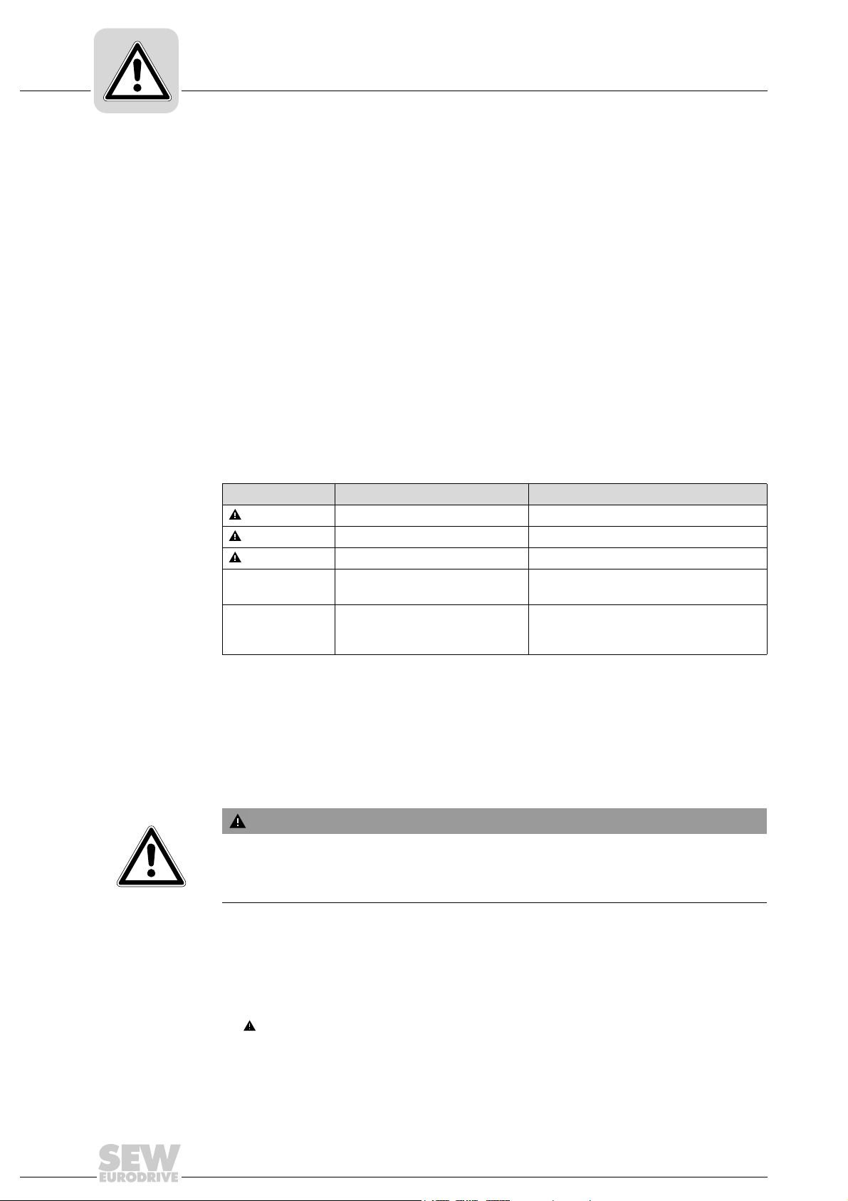
Signal word Meaning Consequences if disregarded
DANGER! Imminent hazard Severe or fatal injuries
WARNING! Possible dangerous situation Severe or fatal injuries
CAUTION! Possible dangerous situation Minor injuries
NOTICE Possible damage to property Damage to the drive system or its envi-
INFORMATION Useful information or tip: Simpli-
fies handling of the drive system.
1.2.2 Design of the section-related safety notes
Section-related safety notes do not apply to a specific action, but to several actions pertaining to one subject. The symbols used either indicate a general hazard or a specific
hazard.
This is the formal structure of a safety note for a specific section:
SIGNAL WORD!
Type and source of danger.
Possible consequence(s) if disregarded.
• Measure(s) to prevent the danger.
ronment
1.2.3 Design of the embedded safety notes
Embedded safety notes are directly integrated into the instructions just before the description of the dangerous action.
This is the formal structure of an embedded safety note:
• SIGNAL WORD! Type and source of hazard.
Possible consequence(s) if disregarded.
– Measure(s) to prevent the hazard.
6
Operating Instructions – MOVIGEAR® SNI-B

1.3 Rights to claim under warranty
A requirement of fault-free operation and fulfillment of any rights to claim under limited
warranty is that you adhere to the information in the documentation. Therefore read the
documentation before you start working with the unit.
1.4 Exclusion of liability
You must comply with the information contained in this documentation to ensure safe
operation and to achieve the specified product characteristics and performance features. SEW-EURODRIVE assumes no liability for injury to persons or damage to equipment or property resulting from non-observance of these operating instructions. In such
cases, any liability for defects is excluded.
1.5 Copyright
© 2013 SEW-EURODRIVE. All rights reserved.
Unauthorized duplication, modification, distribution or any other use of the whole or any
part of this documentation is strictly prohibited.
General information
Rights to claim under warranty
1
1.6 Product names and trademarks
All product names in this documentation are trademarks or registered trademarks of
their respective titleholders.
Operating Instructions – MOVIGEAR® SNI-B
7

2
Safety notes
General information
2 Safety notes
2.1 General information
The following basic safety notes must be read carefully to prevent injury to persons and
damage to property. The operator must ensure that the basic safety notes are read and
adhered to. Ensure that persons responsible for the system and its operation, as well as
persons who work independently on the unit, have read through the operating
instructions carefully and understood them. If you are unclear about any of the information in this documentation, or if you require further information, please contact SEWEURODRIVE.
Never install damaged products or take them into operation. Submit a complaint to the
shipping company immediately in the event of damage.
During operation, MOVIGEAR
parts as well as hot surfaces, depending on their degree of protection.
Removing covers without authorization, improper use as well as incorrect installation or
operation may result in severe injuries to persons or damage to property.
®
drive units can have live, bare and movable or rotating
Refer to the documentation for additional information.
2.2 Target group
Only qualified electricians are authorized to install, start up or service the units or
correct unit faults (observing IEC 60364 or CENELEC HD 384 or DIN VDE 0100 and
IEC 60664 or DIN VDE 0110 as well as national accident prevention guidelines).
Qualified electricians in the context of these basic safety notes are all persons familiar
with installation, assembly, startup and operation of the product who possess the
necessary qualifications.
All persons involved in any other work, such as transportation, storage, operation and
disposal, must be trained appropriately.
8
Operating Instructions – MOVIGEAR® SNI-B
2.3 Designated use
MOVIGEAR® drive units are components intended for installation in electrical systems
or machines.
In case of installation in machines, taking the MOVIGEAR
(i.e. start of designated operation) is prohibited until it is determined that the machine
meets the requirements stipulated in EC Directive 2006/42/EC (Machinery Directive).
Startup (i.e. the start of designated use) is only permitted under observance of EMC
directive 2004/108/EC (EMC Directive).
MOVIGEAR
2006/95/EC. The standards given in the declaration of conformity are applied to the
MOVIGEAR
You must observe the technical data and information on the connection requirements
as provided on the nameplate and in the documentation.
2.3.1 Safety functions
MOVIGEAR
described and expressly permitted.
Safety notes
Designated use
®
drive units into operation
®
drive units comply with the regulations of the Low Voltage Directive
®
drive units.
®
drive units may not perform safety functions unless these functions are
2
2.3.2 Lifting applications
MOVIGEAR
MOVIGEAR
performed a risk assessment. Refer to the relevant information in the documentation.
®
drive units must not be used for lifting applications.
®
drive units may only be used for inclining tracks after the operator has
2.4 Transportation, storage
You must observe the notes in the documentation regarding transportation, storage and
proper handling. Use suitable, sufficiently rated handling equipment (e.g. rope guides)
if required. Do not attach any additional loads. Observe climatic conditions in accordance with the documentation.
The following figure shows the eyebolt of MOVIGEAR
®
drive units:
Operating Instructions – MOVIGEAR® SNI-B
9007202025361803
9

2
Safety notes
Installation
2.5 Installation
2.6 Electrical connection
The units must be installed and cooled according to the regulations and specifications
in the corresponding documentation.
®
Protect the MOVIGEAR
The following applications are prohibited unless explicitly permitted:
• Use in potentially explosive atmospheres.
• Use in areas exposed to harmful oils, acids, gases, vapors, dust, radiation, etc.
• Use in non-stationary applications that are subject to mechanical vibration and shock
loads as stated in the documentation for MOVIGEAR
Important: MOVIGEAR
trude into footways.
Working on live parts of MOVIGEAR® drive units is not permitted.
The drive is operated as a generator due to the kinetic energy of the system/machine.
Secure the output shaft against rotation before opening the wiring compartment.
Electrical installation must be carried out in compliance with pertinent regulations (e.g.
cable cross sections, fusing, protective conductor connection). For any additional information, refer to the applicable documentation.
drive units from improper strain.
®
drive units.
®
drive units and corresponding mount-on parts must not pro-
You find notes on EMC-compliant installation, such as shielding, grounding, arrangement of filters and routing of lines, in the documentation of the MOVIGEAR
The manufacturer of the system or machine is responsible for maintaining the limits established by EMC legislation.
Protective measures and protection devices must comply with the regulations in force
(e.g. EN 60204-1 or EN 61800-5-1).
2.7 Safe disconnection
MOVIGEAR® drive units meet all requirements for safe disconnection of power and
electronics connections in accordance with EN 61800-5-1. All connected circuits must
also satisfy the requirements for safe disconnection to ensure reliable isolation.
®
drive units.
10
Operating Instructions – MOVIGEAR® SNI-B
2.8 Operation
5 minutes
Safety notes
Operation
Systems with integrated MOVIGEAR® drive units must be equipped with additional
monitoring and protection devices according to the applicable safety guidelines, such as
the law governing technical equipment, accident prevention regulations, etc. Additional
protective measures may be necessary for applications with increased potential risk.
Changes to MOVIGEAR
®
drive units using the operating software are permitted.
WARNING
Do not touch live components and power connections immediately after separation of
the MOVIGEAR
still be charged.
Severe or fatal injuries.
• Wait at least for 5 minutes after the supply voltage has been switched off.
®
drive units from the supply voltage because some capacitors might
2
The connection boxes must be closed and screwed on before the supply voltages are
connected to MOVIGEAR
The unit may still be live and connected to the power supply even if the operation LEDs
and other display elements are no longer illuminated.
Mechanical blocking or internal safety functions of the unit can cause a motor standstill.
Eliminating the cause of the problem or performing a reset may result in the drive restarting automatically. If this is not permitted for the driven machine for safety reasons,
disconnect the unit from the supply system before correcting the fault.
Caution: Danger of burns: The surface temperatures of MOVIGEAR
more than 60 °C during operation.
®
drive units.
®
drive units can be
Operating Instructions – MOVIGEAR® SNI-B
11
3
MGF..4/XT
[1]
[2]
[3]
[3]
MGF..4
MOVIGEAR
®
B
MOVIGEAR
®
B
M
O
V
I
G
E
A
R
®
®
B
MGF..2
[4]
[5]
[5]
[5]
[1]
[2]
[4]
[3]
[4]
[1]
[2]
Unit structure
MOVIGEAR® drive unit
3 Unit structure
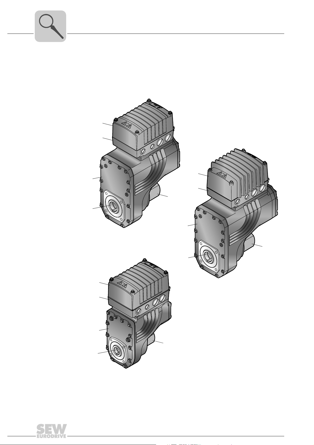
3.1 MOVIGEAR® drive unit
MOVIGEAR® drive units are made up of 3 core components: gear unit, motor and drive
electronics. These 3 core components are included in one die-cast aluminum housing
(see following figure).
36028799382850955
[1] MOVIGEAR® electronics cover
[2] Connection ring for cable glands
[3] Inspection cover
[4] Output shaft variant (pictured here: hollow shaft with keyway)
12
[5] Optional cover
Operating Instructions – MOVIGEAR® SNI-B
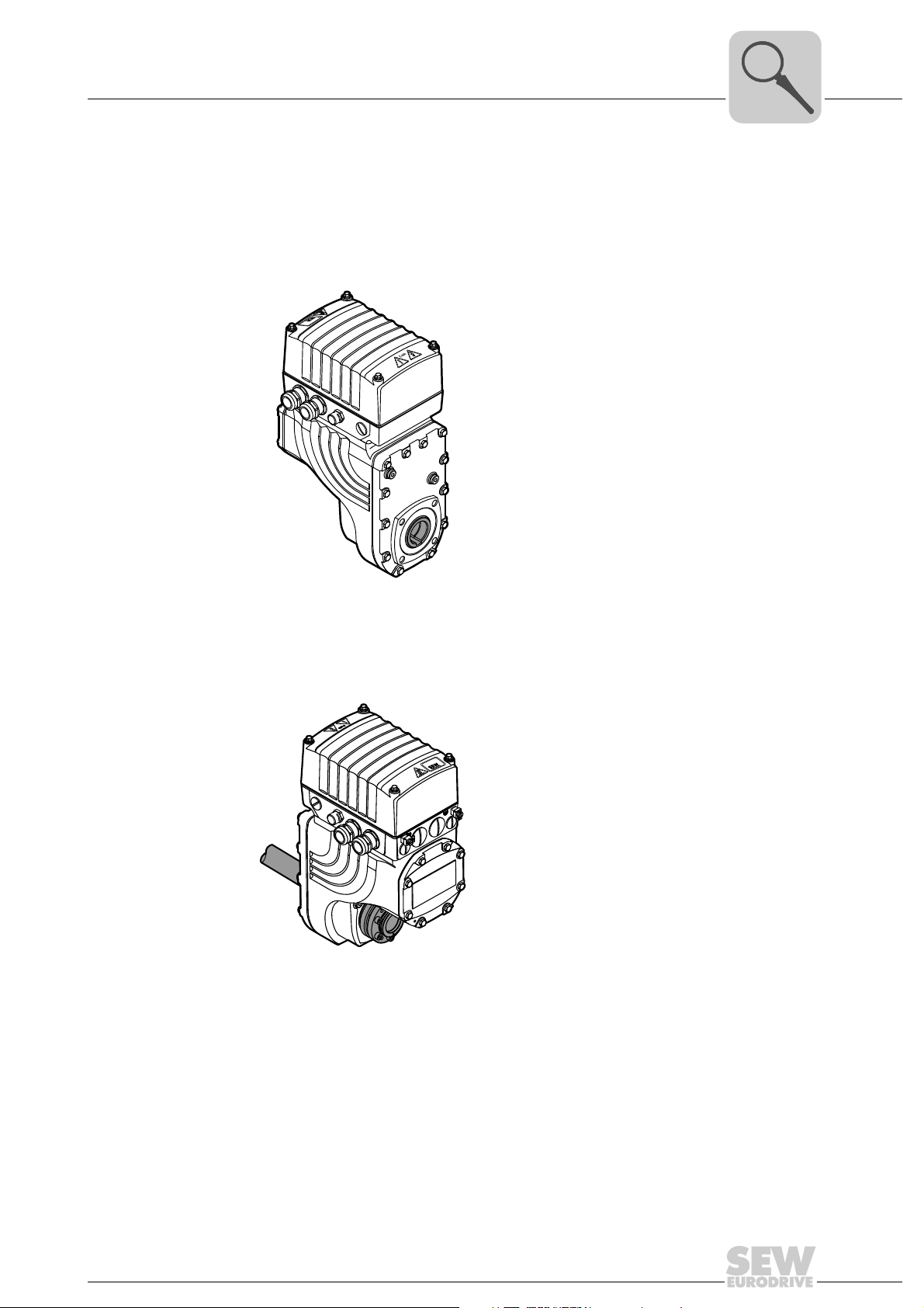
3.2 Shaft types
3.2.1 MOVIGEAR
®
Unit structure
MOVIGEAR® is available with the following shaft types:
with hollow shaft and keyway (MGFA..)
The following figure shows a MOVIGEAR
®
unit with hollow shaft and keyway:
Shaft types
3
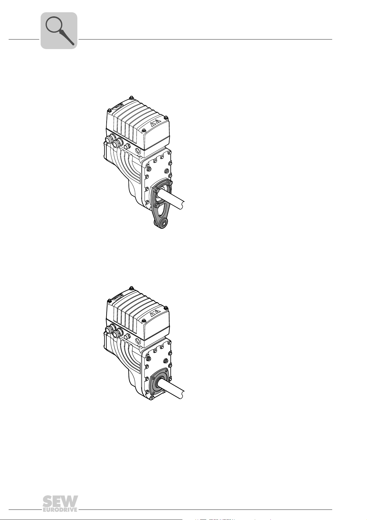
3.2.2 MOVIGEAR
18014401200302603
®
with TorqLOC® hollow shaft mounting system (MGFT..)
The following figure shows a MOVIGEAR
system
18014401200304523
®
unit with TorqLOC® hollow shaft mounting
Operating Instructions – MOVIGEAR® SNI-B
13
3
Unit structure
Housing mounting
3.3 Housing mounting
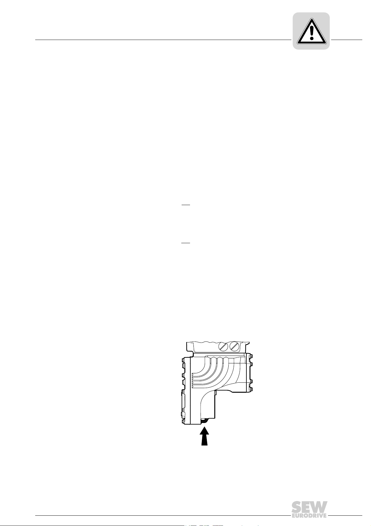
3.3.1 Torque arm (MGF.T)
The following figure shows the torque arm for MGF.T:
3.3.2 Housing with threads (MGF.S)
The following figure shows the housing type with threads for mounting a torque arm.
This type does not include a centering shoulder, which means it is not suitable for direct
installation to the machine:
18014401200308363
18014401200306443
14
Operating Instructions – MOVIGEAR® SNI-B
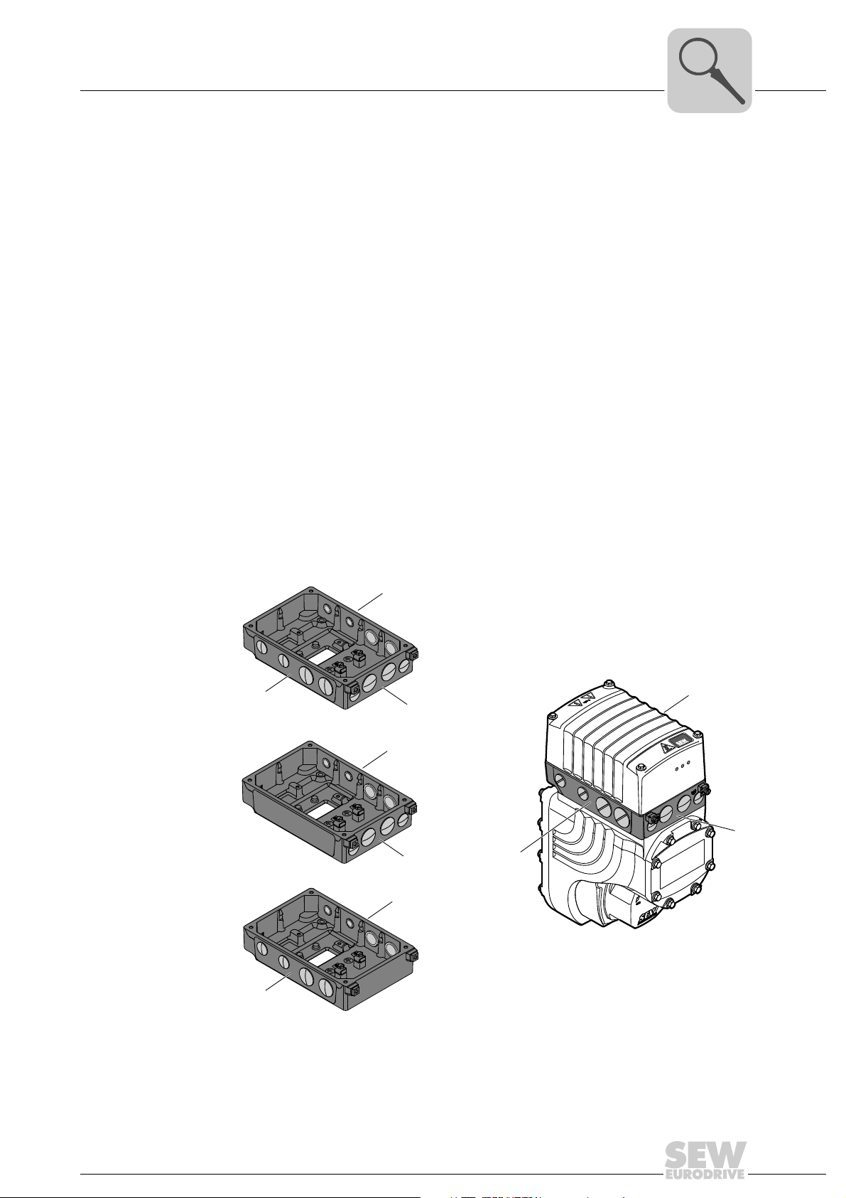
3.4 Cable entry positions
The following cable entries are possible for MOVIGEAR® drive units:
• Position X + 2
– X: 2 x M25 x 1.5 + 2 x M16 x 1.5
– 2: 2 x M25 x 1.5 + 2 x M16 x 1.5
• Position X + 2 + 3
– X: 2 x M25 x 1.5 + 2 x M16 x 1.5
– 2: 2 x M25 x 1.5 + 2 x M16 x 1.5
– 3: 2 x M25 x 1.5 + 2 x M16 x 1.5
• Position X + 3
– X: 2 x M25 x 1.5 + 2 x M16 x 1.5
– 3: 2 x M25 x 1.5 + 2 x M16 x 1.5
• Position 2 + 3
– 2: 2 x M25 x 1.5 + 2 x M16 x 1.5
Unit structure
Cable entry positions
3
3.4.1 Overview
– 3: 2 x M25 x 1.5 + 2 x M16 x 1.5
The following figure shows the possible cable entries:
2
X
3
2
3
X
2
MOVIGEAR
NET
2
®
B
DRIVE
RUN
3
X
Operating Instructions – MOVIGEAR® SNI-B
18014401200378763
15
3
76646 Bruchsal/Germany
Nm
°C
n
R
U
N
f
N
Nm
n
A
A
M
A
M
a pk
i
Made in Germany
IM
kg
cos
IP
r/min
Hz
V
13356887
MGFAT2-DSM-SNI-B/DSP
01.1233697403.0001.08
5,4...53,7
37,24
M1,M2,M4,M5,M6 50...60
380...500
65
0,99
1,52
1/10
16.000
CLP HC 220 Synth.Öl/0,55l
0 ... +40
[1]
[2]
3~ EN61800
TENV
M.L.
149
220
eff%
86,3
IE4
Unit structure
Example nameplate and type designation of the drive unit
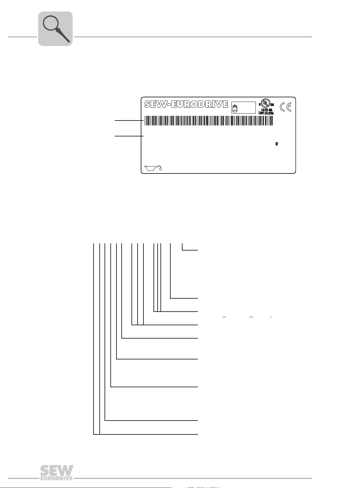
3.5 Example nameplate and type designation of the drive unit
3.5.1 Nameplate
The following figure gives an example of a MOVIGEAR
of the type designation, refer to chapter "Type designation".
[1] Unique serial number
[2] The bar code on the nameplate (code 39) according to ISO/IEC 16388 represents the unique
serial number (with a period as separator).
®
nameplate. For the structure
18014400877661323
3.5.2 Type designation
16
The following table shows the type designation of MOVIGEAR
MGFAS2–DSM–SNI–B / DSP
MOVIGEAR® option
Electrodynamic
=
DSP
deceleration function DynaStop
=
Extended control range
=
Increased torque
=
Plug connectors
=
Version for use in wet areas
®
version
®
installation technology
ingle Line Network Installation
==Torque class 200 Nm
Torque class 400 Nm
Drive with torque arm
Housing with threads for
mounting a torque arm
(hollow shaft with key)
To rq L OC
tem
Operating Instructions – MOVIGEAR® SNI-B
ECR
XT
IV
WA
MOVIGEAR
MOVIGEAR
SNI = S
Motor type
Frame size
2
4
Housing mounting
T
S ==
Shaft type
A T= =Shaft-mounted gear unit
Gear unit type
F = Parallel-shaft helical gear units
Product line
MG = MOVIGEAR
®
:
®
®
hollow shaft mounting sys-
®
3.6 Electronics
[1]
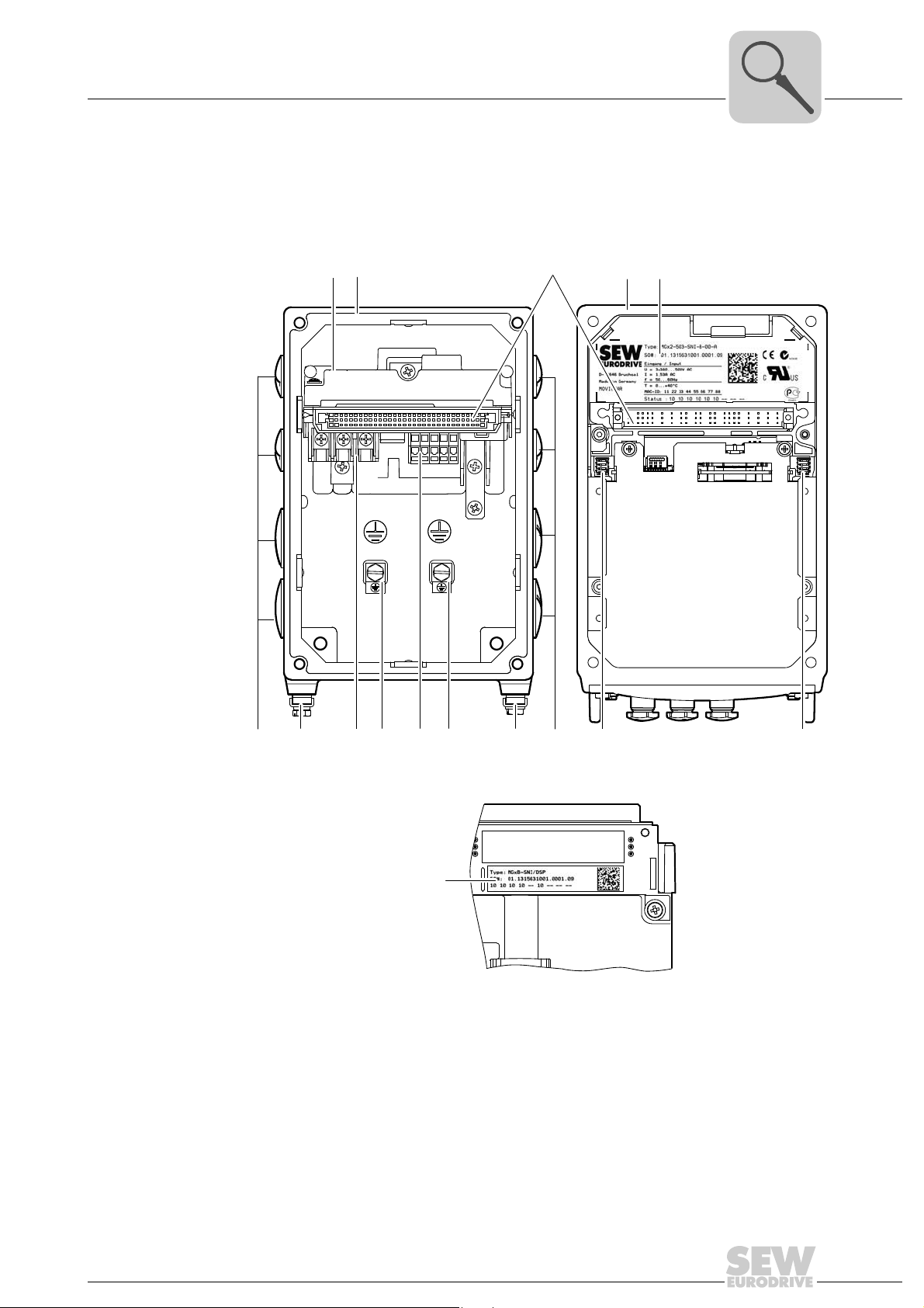
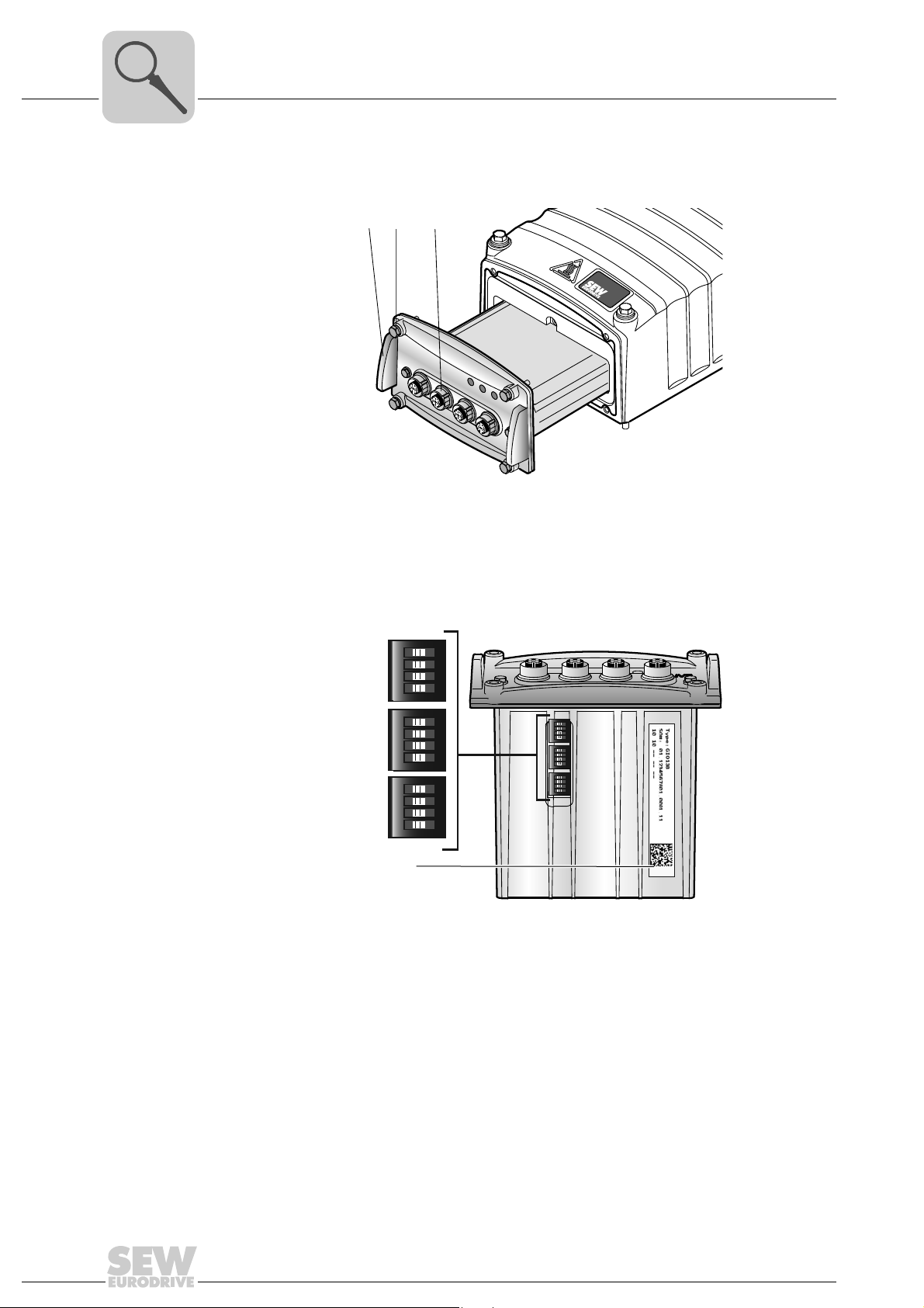
3.6.1 MOVIGEAR® electronics cover (inside) and connection box
The following figure shows the connection box and the bottom side of the MOVIGEAR
electronics cover:
Unit structure
Electronics
3
®
[1]
[2]
[3]
[4] [5]
[7] [7][7]
[6]
[1] Nameplate of drive unit, see following detailed view
[2] Connection ring
[3] Plug connector connection unit for MOVIGEAR
[4] MOVIGEAR
[5] Electronics cover nameplate
[6] Cable glands
[7] Screws for PE connection
[8] Line connection L1, L2, L3
[9] Electronics terminal strips
[10] DIP switches S2/1 – S2/4
[11] DIP switches S1/1 – S1/4
[7]
[8] [10] [11]
®
electronics cover
[9]
[6]
®
electronics cover
2389525515
2584370315
Operating Instructions – MOVIGEAR® SNI-B
17
3
NET
RUN
DRIVE
NET
RUN
DRIVE
[1]
[1] [2] [3] [4]
AB
Unit structure
Electronics
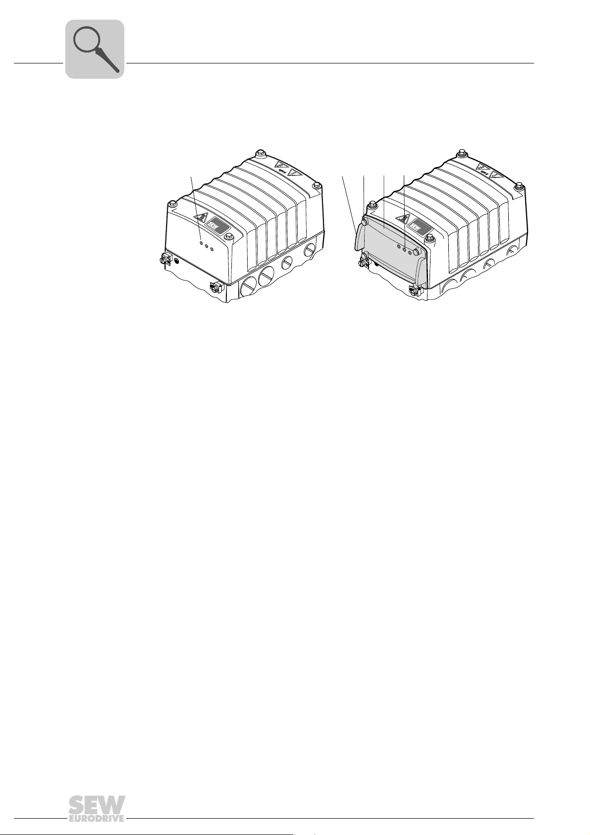
3.6.2 Electronics cover (outside)
The following figure shows the possible variants of the electronic cover using one frame
size as an example:
A Electronics cover without application slot B Electronics cover with application slot
[1] LED displays [1] Assembly/disassembly handle
18014400877430923
[2] Retaining screws (4x)
[3] Application cover
[4] LED displays
18
Operating Instructions – MOVIGEAR® SNI-B

3.7 Application options
[1] [2] [3]
NET
RUN
DRIVE
X4
X3
X2
X1
[1]
3.7.1 GIO12B application option
The following figure shows the GIO12B application option:
Unit structure
Application options
3
[1] Assembly/disassembly handle
[2] Retaining screws (4x)
[3] M12 plug connector for digital I/Os
The following figure shows the position of the GIO12B nameplate:
[1] Nameplate
9007201622841227
18014401210968331
Operating Instructions – MOVIGEAR® SNI-B
19
3
NE
T
RUN
DRIVE
ON
1234
ON
1234
ON
1234
ON
1234
ON
1234
S1
S2
S3
ON
1234
[1]
Unit structure
Application options
3.7.2 GIO13B application option
The following figure shows the GIO13B application option:
[1] [2] [3]
X4
X3
X2
X1
9007201839769867
[1] Assembly/disassembly handle
[2] Retaining screws (4x)
[3] M12 plug connector for digital/analog I/Os
The following figure shows the DIP switches S1 to S3 of the GIO13B application option:
18014401245670283
[1] Nameplate
20
Operating Instructions – MOVIGEAR® SNI-B
Unit structure
[1]
[3]
[2]
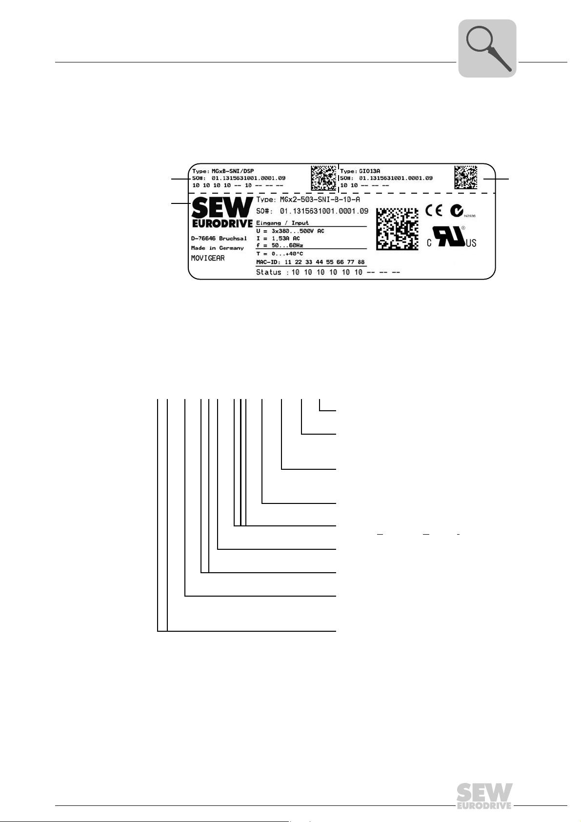
Example nameplate and type designation of electronics
3.8 Example nameplate and type designation of electronics
3.8.1 Nameplate
®
The following figure gives an example of a MOVIGEAR
of the type designation, refer to chapter "Type designation".
[1] Nameplate of connection unit
[2] Nameplate of application option
[3] Electronics cover nameplate
nameplate. For the structure
3
9007201839835019
3.8.2 Type designation of electronic cover
The following table shows the type designation of the electronics cover:
M Gx 4–5 0 3–SNI–B – 10 – A / XT
1)
MGF..4/XT has a different connection voltage range, see chapter "Technical data"
Electronics cover option
XT = Increased torque
Electronics cover variant
A = With application slot
0 = Without application
Design
1011==Die-cast design (standard)
Die-cast design (wet areas)
MOVIGEAR
MOVIGEAR
SNI = S
Connection type
3 = 3-phase
Connection voltage
50 = AC 380 – 500 V
Size
2 4==Torque class 200 Nm
Product line
MG = MOVIGEAR
®
version
®
installation technology
ingle Line Network Installation
1)
Torque class 400 Nm
®
Operating Instructions – MOVIGEAR® SNI-B
21
3
Unit structure
Example nameplate and type designation of electronics
3.8.3 Type designation of connection unit
The following table shows the type designation of the connection unit:
M G x B – SNI / DSP
Connection unit option
DSP = Electrodynamic
deceleration function DynaStop
MOVIGEAR
SNI = S
MOVIGEAR
®
installation technology
ingle Line Network Installation
®
version
®
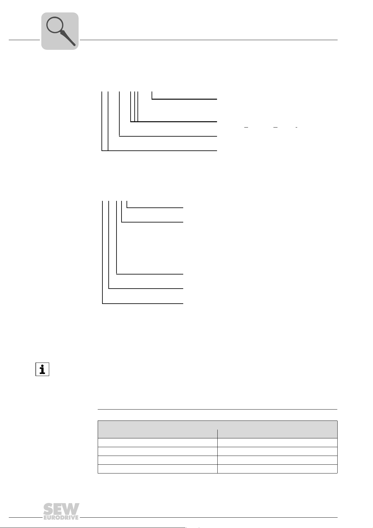
3.8.4 Type designation of application options
The following table shows the type designation of application options:
G IO 1 2 B
Note on the version of the application option
Product line
MG = MOVIGEAR
Version
Design
2 = 4 digital inputs + 2 digital outputs
3 = 4 digital inputs
(2 inputs can be used as primary frequency input)
+ 1 digital output
+ 1 analog input
+ 1 analog output
Version
Functionality
IO = Digital inputs/outputs
Product line
G = Option for MOVIGEAR
®
/ DRC
®
22
INFORMATION
For electronics covers in die-cast design, you can only use application options
GIO12B and GIO13B. For electronics covers in sand-cast design, you can only use
application options GIO12A and GIO13A .
You can identify units with die-cast housing by means of the type designation of the
electronics cover.
Application options
Design Part number
GIO12A application option On request
GIO13A application option On request
GIO12B application option Part number 1 823 801 7
GIO13B application option Part number 1 822 652 3
Operating Instructions – MOVIGEAR® SNI-B
Unit structure
M
O
V
I
G
E
A
R
®
B
NET
RUN
DRIVE
MOVIGEAR
®
B
M
O
V
I
G
E
A
R
®
B
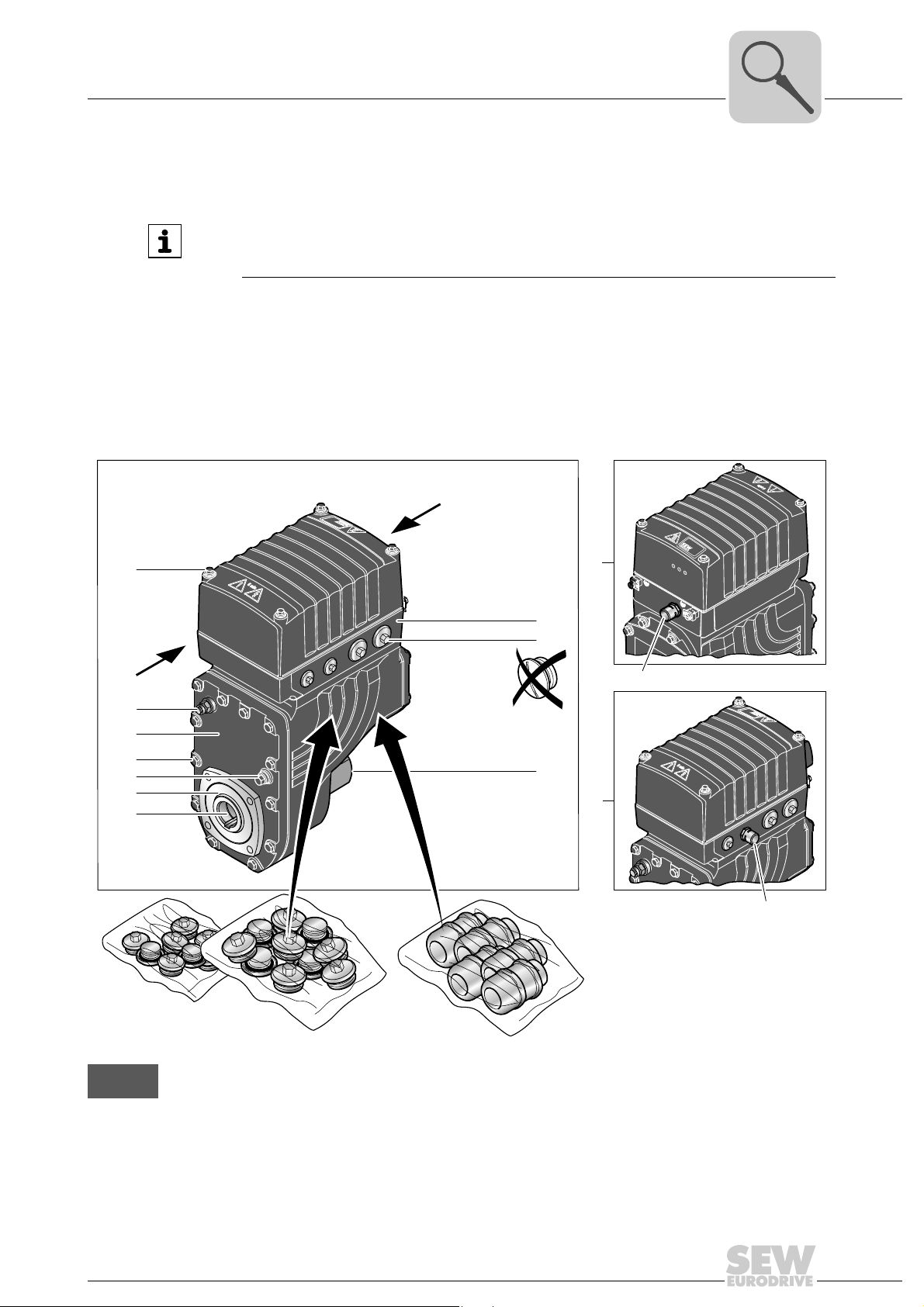
MOVIGEAR® with optional design for wet areas (/WA option)
3.9 MOVIGEAR® with optional design for wet areas (/WA option)
INFORMATION
Slight color differences are possible in the HP200 surface finish due to the treatment
process (individual treatment of the components).
®
The following figure shows the additional features of ® drive units with the optional ver-
sion for applications in wet areas (/WA option):
• The variant for use in wet areas is delivered as standard with screw plugs made of
stainless steel.
• Plastic screw plugs can be chosen instead. To achieve degree of protection IP66 and
compatibility with cleaning agents, you have to replace the plastic screw plugs by
suitable screw fittings made of stainless steel.
3
A
[A1]
[A2]
[A3]
[A4]
[A5]
[A6]
[A7]
X
[A 2]
Y
Y
[A8]
[A9]
[A12]
[A10]
X
[A13]
B
[B 1]
In this publication, all illustrations depicting the version for use in wet areas are displayed with a shading
(= HP200 surface protection).
Operating Instructions – MOVIGEAR® SNI-B
[B 2]
8796664203
23

3
A Scope of delivery
[A1] Mounting screws for cover made of stainless steel
[A2] Breather valve mounted and activated according to mounting position, see chapter "Technical data
[A3] HP200 surface protection, see chapter "Technical data and dimension sheets"
[A4] Mounting screws for gear unit housing made of stainless steel
[A5] Oil screw plug made of stainless steel (hexagon)
[A6] Fluorocarbon rubber oil seal
[A7] Output shaft made of stainless steel
[A8] Connection ring only possible with cable outlet pointing "downward" or "on the side":
[A9] Standard:
[A10] Additional cover opposite the output side
[A12] Factory-installed pressure compensation fitting (M16) with mounting positions M5, M6
[A13] Factory-installed pressure compensation fitting (M16) with mounting position M1, M2, M3*, M4
Unit structure
MOVIGEAR® with optional design for wet areas (/WA option)
and dimension sheets"
– In connection with mounting positions M1, M2, M3*: 2 + 3, 2 + X, X + 3, 2 + X + 3
– In connection with mounting position M4: 2 + X
– In connection with mounting position M5: X + 3
– In connection with mounting position M6: 2 + 3
Optional:
Screw plugs made of stainless steel Plastic screw plugs. To achieve degree of pro-
tection IP66 and compatibility with cleaning
agents, you have to replace the plastic screw
plugs by suitable screw fittings made of stainless
steel.
Optional plug connectors (see chapter "Electrical installation") are available in connection with the
design for wet areas.
B Required screw fittings
[B1] Screw plugs made of stainless steel, if required
[B2] Cable glands made of stainless steel
* = Mounting position M3 only possible after consultation with SEW-EURODRIVE
The required screw fittings can be ordered from SEW-EURODRIVE. For an overview, refer to chapter "Optional metal screw fittings".
1)
Make sure to select plug seals that are compatible with the used cleaning agents
1)
1)
24
Operating Instructions – MOVIGEAR® SNI-B
4 Mechanical installation
4.1 Installation notes
INFORMATION
Adhere to the safety notes during installation.
WARNING
Improper installation/disassembly of MOVIGEAR® drive units and mount-on components.
Risk of injury.
• Adhere to the notes about installation and disassembly.
• Before releasing shaft connections, make sure that there are no active torsional
moments present (tensions within the system).
Mechanical installation
Installation notes
4
WARNING
Risk of injury if the drive starts up unintentionally and danger of electrical voltage.
Dangerous voltages may still be present for up to 5 minutes after disconnection from
the power supply.
Severe or fatal injuries.
5 minutes
• Disconnect the MOVIGEAR
working on the unit and secure it against unintentional reconnection to the power
supply.
• Secure the output shaft against rotation.
• Wait for at least 5 minutes before removing the electronics cover.
4.2 Required tools and resources
• Set of wrenches
• Torque wrench
• Mounting device
• Compensation elements (shims and spacing rings), if necessary
• Mounting materials for output components
• Lubricant (e.g. NOCO
• Standard parts are not included in the delivery
®
Fluid)
®
drive unit from the power supply before you start
4.2.1 Installation tolerances for shaft ends
Diameter tolerance in accordance with DIN 748:
• ISO H7 for hollow shafts
4.2.2 Tolerances for torque ratings
The specified torques must be adhered to with a tolerance of +/− 10% .
Operating Instructions – MOVIGEAR® SNI-B
25

4
Mechanical installation
Installation requirements
4.3 Installation requirements
Check that the following conditions have been met:
• The entries on the nameplate of the MOVIGEAR
tem.
• The drive is undamaged (no damage caused by transportation or storage)
• Ambient temperature according to the operating instructions, nameplate and lubricant table in chapter "Technical data/lubricants".
• The drive must not be assembled in the following ambient conditions:
– Potentially-explosive atmosphere
– Oils
–Acids
– Gases
– Vapors
– Radiation
• For special designs: The drive is designed in accordance with the actual ambient
conditions.
• Clean the output shafts and flange surfaces thoroughly to ensure they are free of
anti-corrosion agents, contamination or similar. Use a commercially available solvent. Do not expose the sealing lips of the oil seals to the solvent – damage to the
material.
®
unit match the voltage supply sys-
• When the drive is installed in abrasive ambient conditions, protect the output end oil
seals against wear.
26
Operating Instructions – MOVIGEAR® SNI-B

4.4 Setting up the drive unit
4.4.1 Information
• Clean the output shafts thoroughly to ensure they are free of anti-corrosion agents
(use a commercially available solvent). Do not expose the bearings and sealing rings
to the solvent – damage to the material!
• Carefully align the MOVIGEAR
any unacceptable strain on the motor shafts (observe permissible overhung loads).
• Do not butt or hammer the shaft end.
• Ensure that cooling air supply is unobstructed and that air discharged by other units
does not influence cooling.
• Use suitable cable glands for the supply leads (use reducing adapters if necessary).
• Seal the cable entry well.
• Clean the sealing faces of the MOVIGEAR
• Restore the corrosion protection if necessary.
• Check the validity of the degree of protection using the information in the operating
instructions and the data on the nameplate.
Mechanical installation
Setting up the drive unit
®
drive unit and the driven machine to avoid placing
®
cover well before reassembling the unit.
4
Change in mounting position
Make sure to read the following information when you operate the drive unit in a mounting position other than the one indicated in the order:
• Adjust the position of the breather valve and, if necessary, the position of the
pressure compensation fitting.
Operating Instructions – MOVIGEAR® SNI-B
27
4
NET RUN DRIVE
MOVIGEAR
®
B
SNI
NET RUN DRIVE
MOVIGEAR
®
B
SNI
4.4.2 Electronics cover
Mechanical installation
Setting up the drive unit
WARNING
Burns caused by hot surfaces.
Severe injuries.
• Let the units cool down before touching them.
NOTICE
Loss of the guaranteed degree of protection.
Possible damage to property.
• When the MOVIGEAR
have to protect it from humidity, dust or foreign particles.
• Check to see that the MOVIGEAR
®
electronics cover is removed from the connection box, you
®
electronics cover was mounted properly.
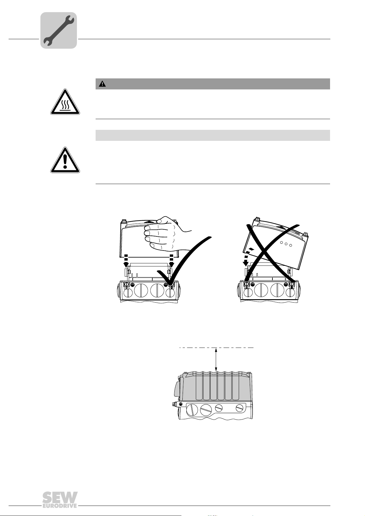
Installing the
electronics cover
Minimum installation clearance
• Use only electronics covers that match the size.
• Be careful not to tilt the electronics cover when placing it on the connection box.
4813126155
Note the minimum installation clearance (see following figure) required to remove the
MOVIGEAR
®
electronics cover. For detailed dimension drawings, refer to chapter
"Technical Data".
100
28
9007201604838411
Operating Instructions – MOVIGEAR® SNI-B
Mechanical installation
Setting up the drive unit
4
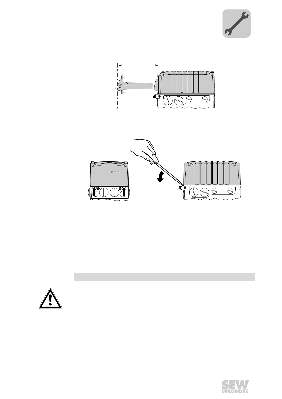
Min. installation
clearance of
application options
Removing the
electronics cover
Note the minimum installation clearance (see following figure) required to install and
remove the application options.
200
9007201604871563
The following figure shows how you can lever off the electronics cover in the intended
places.
NET RUN DRIVE
4.4.3 Installation in damp locations or in the open
Drives are supplied in corrosion-resistant versions for use in damp areas or in the open.
Repair any damage to the paint work if necessary.
For variants with HP200 surface treatment, observe the notes in chapter "Drive units
with optional design for wet areas".
4.4.4 Painting drive units
NOTICE
Breather valves and oil seals may be damaged during painting or re-painting.
Potential damage to property.
• Clean the surface of the drive unit and make sure it is free from grease.
• Thoroughly cover the breather valves and sealing lip of the oil seals with strips prior
to painting.
• Remove the strips after painting.
8962548363
Operating Instructions – MOVIGEAR® SNI-B
29
4
4.4.5 Gear unit venting
Drive units with
installed breather
valve
Mechanical installation
Setting up the drive unit
Except for the M3 mounting position, SEW-EURODRIVE delivers all MOVIGEAR
units ordered for a specific mounting position with a breather valve that is activated and
installed according to the specific mounting position.
MOVIGEAR
the activated breather valve installed corresponding to the respective mounting position.
®
drive units with optional "design for wet areas" are generally delivered with
®
drive
Drive units with
separately
included breather
valve
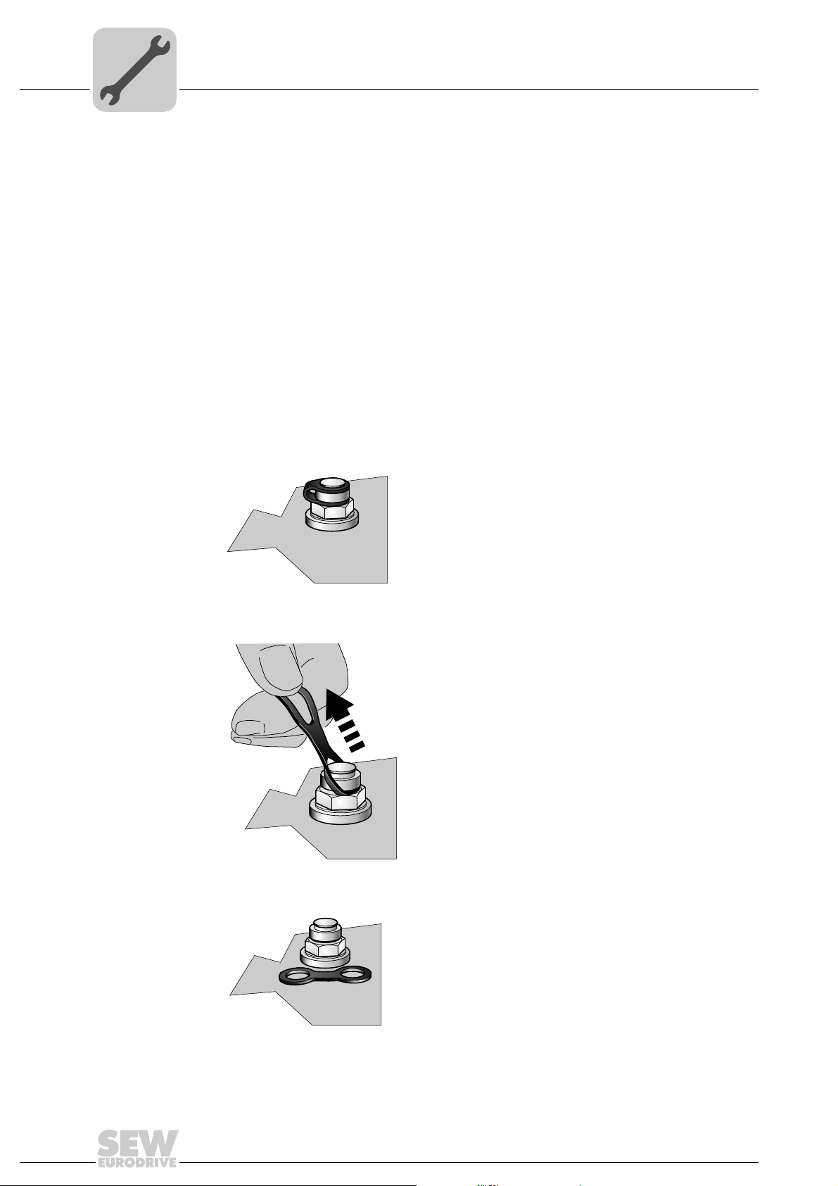
Activating the
breather valve
SEW-EURODRIVE delivers MOVIGEAR
position with a separately included breather valve.
In this case, the breather valve is delivered in the hollow shaft of the drive unit. Before
startup, you must replace the highest oil screw plug with the provided breather valve.
Once you have installed the breather valve, activate it as follows. For designs with the
breather valve screwed in: Check whether the breather valve is activated. If not, you
have to remove the transport fixture of the breather valve before you start up the drive
unit.
1. Breather valve with transportation protection device
2350149003
2. Remove the transport fixture
®
drive units ordered for a universal mounting
30
2350216203
3. Activated breather valve
2350269835
Operating Instructions – MOVIGEAR® SNI-B
 Loading...