

SEW MOVIFIT SC series Operating Instructions Manual
Gearmotors \ Industrial Gear Units \ Drive Electronics \ Drive Automation \ Services
MOVIFIT® SC
Edition 02/2007
11574615 / EN
O
perating
I
nstructions

SEW-EURODRIVE – Driving the world

Contents
1 General Information .......................................................................................... 5
1.1 Structure of the safety notes ..................................................................... 5
1.2 Right to claim under warranty ................................................................... 5
1.3 Exclusion of liability ................................................................................... 5
2 Safety Notes ...................................................................................................... 6
2.1 General information .................................................................................. 6
2.2 Target group ............................................................................................. 6
2.3 Designated use ......................................................................................... 6
2.4 Other applicable documentation ............................................................... 7
2.5 Transportation, putting into storage .......................................................... 7
2.6 Installation................................................................................................. 7
2.7 Electrical connection ................................................................................. 7
2.8 Safe disconnection.................................................................................... 8
2.9 Operation .................................................................................................. 8
3 Index of Changes .............................................................................................. 9
3.1 Changes compared to the previous version.............................................. 9
4 Unit Design ...................................................................................................... 11
4.1 Overview ................................................................................................. 11
4.2 EBOX (active electronics unit) ................................................................ 12
4.3 ABOX (passive connection unit) ............................................................. 13
plus
4.4 Hygenic
4.5 Unit designation MOVIFIT
version (optional) ................................................................. 16
®
SC............................................................... 18
5 Mechanical Installation ................................................................................... 20
5.1 Installation instructions............................................................................ 20
5.2 Approved installation position ................................................................. 20
5.3 Installation notes ..................................................................................... 21
5.4 Central opening/closing mechanism ....................................................... 24
5.5 Tightening torques .................................................................................. 26
5.6 Hygenicplus version................................................................................ 27
6 Electrical Installation ...................................................................................... 30
6.1 Installation planning with regard to EMC issues ..................................... 30
6.2 Installation instructions (all versions) ...................................................... 31
6.3 ABOX with terminals and cable glands "MTA...-S02.-...-00"................... 35
6.4 Hybrid ABOX "MTA...-S12.-...-00" and "MTA...-S22.-...-00" ................... 50
®
6.5 HanModular
ABOX "MTA...-H12.-...-00" and "MTA...-H22.-...-00"........ 65
6.6 Power bus connection examples ............................................................ 79
6.7 Fieldbus systems connection examples.................................................. 82
6.8 PC connection ........................................................................................ 86
6.9 Hybrid cables .......................................................................................... 87
7 Startup.............................................................................................................. 92
7.1 Startup instructions ................................................................................. 92
7.2 Startup procedure for MOVIFIT
7.3 Startup MOVIFIT
7.4 Startup MOVIFIT
8 Operation ....................................................................................................... 104
8.1 MOVIFIT
Operating Instructions – MOVIFIT® SC
®
®
................................................................................... 96
®
motor starter ........................................................... 100
®
SC operating displays ......................................................... 104
SC ...................................................... 95
3

Contents
9 Service ........................................................................................................... 116
9.1 Unit diagnostics..................................................................................... 116
9.2 SEW Electronics Service ...................................................................... 119
9.3 Disposal ................................................................................................ 119
10 Technical Data ............................................................................................... 120
10.1 CE marking, UL approval and C-Tick.................................................... 120
10.2 General technical data .......................................................................... 121
10.3 General electronics data ....................................................................... 123
10.4 Digital inputs ......................................................................................... 123
10.5 Digital outputs DO00...DO03................................................................. 124
10.6 Digital outputs DB00...DB01 ................................................................. 124
10.7 Interfaces .............................................................................................. 125
10.8 Hybrid cable "Cable type A" .................................................................. 127
10.9 Hygenic
10.10 Dimension drawings.............................................................................. 132
plus
version ............................................................................... 129
4
Operating Instructions – MOVIFIT® SC
General Information
Structure of the safety notes
1 General Information
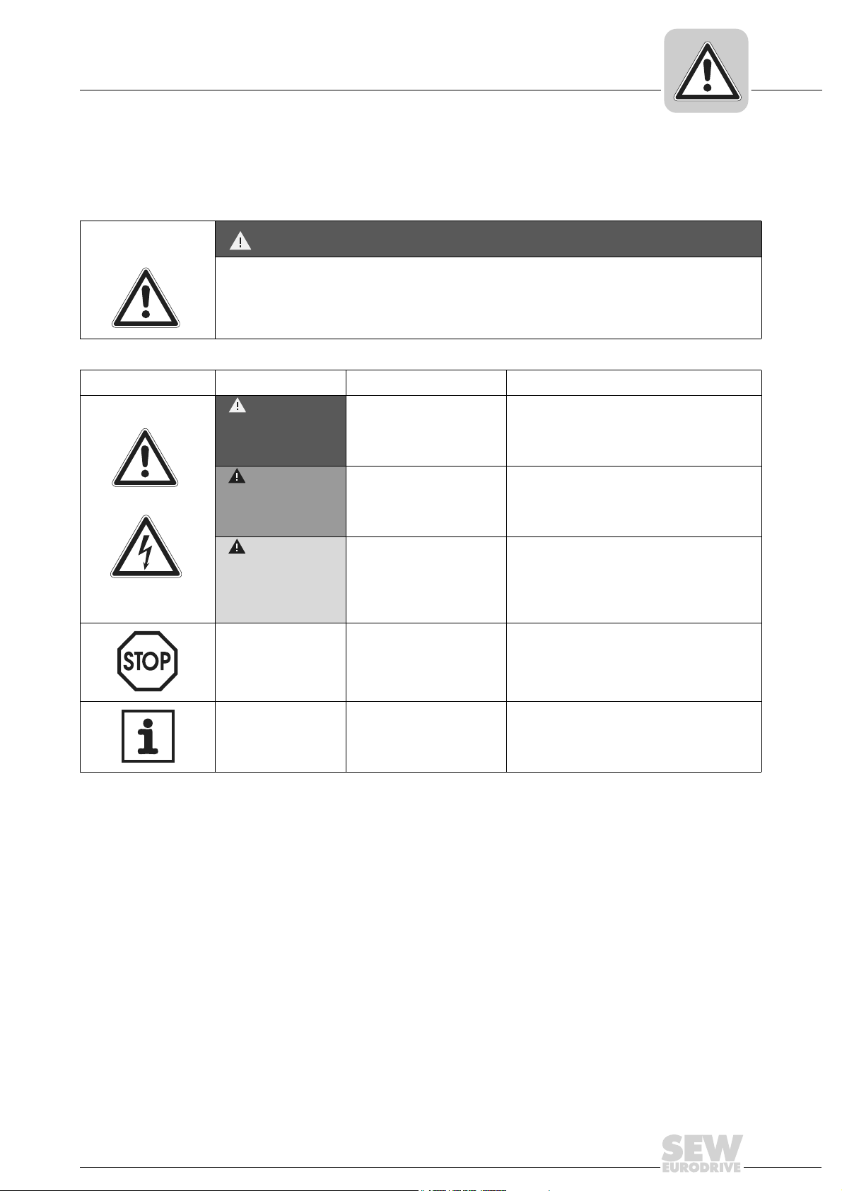
1.1 Structure of the safety notes
The safety notes in these operating instructions are structured as follows:
Symbol SIGNAL WORD!
Type and source of danger
Possible consequence(s) if the safety notes are disregarded
• Measure(s) to prevent the danger
Symbol Signal word Meaning Consequences if disregarded
Example:
DANGER Imminent danger Severe or fatal injuries
1
WARNING Possible dangerous situation Severe or fatal injuries
General danger
CAUTION! Possible dangerous situation Minor injuries
Specific danger,
e.g. electric shock
STOP! Possible damage to property Damage to the drive system or its environment
NOTE Useful information or a tip
Simplifies the handling of the
drive system
1.2 Right to claim under warranty
Adhering to the operating instructions is prerequisite for fault-free operation and the
fulfillment of any right to claim under warranty. Read the operating instructions before
you start working with the unit.
Make sure that the operating instructions are available to persons responsible for the
system and its operation as well as to persons who work independently on the unit. You
must also ensure that the documentation is legible.
1.3 Exclusion of liability
You must comply with the information contained in these operating instructions to
ensure safe operation of MOVIFIT
mance features. SEW-EURODRIVE assumes no liability for injury to persons or
damage to equipment or property resulting from non-observance of these operating
instructions. In such cases, any liability for defects is excluded.
Operating Instructions – MOVIFIT® SC
®
SC and to achieve the specified product and perfor-
5

2
Safety Notes
General information
2 Safety Notes
2.1 General information
The following basic safety notes must be read carefully to prevent injury to persons and
damage to property. The operator must make sure that the basic safety notes are read
and observed. Make sure that persons responsible for the system and its operation, as
well as persons who work independently on the unit, have read through the operating
instructions carefully and understood them. If you are unclear about any of the information in this documentation, or if you require further information, please contact SEWEURODRIVE.
Never install or startup damaged products. In the event of damage, submit a complaint
to the shipping company immediately.
During operation, MOVIFIT
lated, and sometimes moving or rotating parts as well as hot surfaces.
Removing required covers without authorization, faulty use and incorrect installation or
operation may result in severe injuries to persons or damage to property.
Consult the documentation for additional information.
®
SC, depending on the enclosure, may have live, uninsu-
2.2 Target group
Only qualified personnel should perform installation, startup, fault repair and servicing
(observe IEC 60364 or CENELEC HD 384 or DIN VDE 0100 and IEC 60664 or DIN VDE
0110 as well as national accident prevention guidelines).
In the context of these basic safety notes, electricians are persons familiar with installation, assembly, startup, and operation of the product who possess the necessary qualifications for their work.
All activity in the other areas of transportation, storage, operation, and waste disposal
must be carried out by persons who are appropriately trained.
2.3 Designated use
MOVIFIT® SC is a component intended for installation in electrical systems or
machines.
When installed in machines, startup of the MOVIFIT
is prohibited until it is determined that the machine meets the requirements stipulated in
EC directive 98/37/EC (Machine directive).
Startup (i.e. the start of designated use) is only permitted in compliance with EMC directive (89/336/EEC).
MOVIFIT
2006/95/EC. The standards contained in the declaration of conformity are used for
MOVIFIT
Technical data and information on the connection requirements are provided on the
nameplate and in the documentation; these must be observed under all circumstances.
®
SC (i.e. start of designated use)
®
SC meets the requirements stipulated in the low voltage directive
®
SC.
6
Operating Instructions – MOVIFIT® SC

Safety Notes
Other applicable documentation
Safety functions MOVIFIT® SC may not perform any safety functions unless they are described and
expressly approved.
Use only components in safety applications that were explicitly delivered in this version
by SEW-EURODRIVE.
2.4 Other applicable documentation
The following publication must also be observed:
• "DR/DV/DT/DTE/DVE AC Motors, CT/CV Asynchronous Servomotors" operating
instructions
2.5 Transportation, putting into storage
Observe the notes on transportation, storage, and proper handling. Observe the climatic
conditions as stated in the section "Technical Data".
2.6 Installation
2
Installation and cooling of the devices must be carried out according to the guidelines
listed in the corresponding documentation.
Protect MOVIFIT
The following applications are prohibited unless measures are expressly taken to make
them possible:
• Use in potentially explosive atmospheres
• Use in areas exposed to harmful oils, acids, gases, vapors, dust, radiation, etc.
• Use in non-stationary applications with strong mechanical oscillation and impact
loads; see section "Technical Data".
2.7 Electrical connection
Observe applicable national accident prevention guidelines when working on live
MOVIFIT
Electrical installation must be carried out according to pertinent regulations (e.g. cable
cross-sections, fusing, protective earth connection). For any additional information, refer
to the applicable documentation.
You will find notes on EMC-compliant installation (e.g. shielding, grounding, configuration of filters and routing of lines) in the MOVIFIT
of the system or machine is responsible for maintaining the limits established by EMC
legislation.
Preventive measures and protection devices must comply with the regulations in force
(e.g. EN 60204 or EN 61800-5-1).
®
SC (e.g. BGV A3).
®
SC from excessive strain.
®
SC documentation. The manufacturer
Operating Instructions – MOVIFIT® SC
7

2
Safety Notes
Safe disconnection
2.8 Safe disconnection
2.9 Operation
MOVIFIT® SC meets all requirements for safe disconnection of power and electronic
connections in accordance with EN 61800-5-1. All connected circuits must also satisfy
the requirements for safe disconnection.
Systems into which MOVIFIT® SC is installed must be equipped with additional monitoring and protection devices, if necessary, according to the applicable safety regulations; e.g. the law governing technical equipment, accident prevention regulations, etc.
When used in applications with an increased potential for risk, additional preventive
measures may be necessary. Changes to the MOVIFIT
permitted.
Do not touch live components or power connections immediately after disconnecting the
MOVIFIT
itors. Wait at least 1 minute after the supply voltage is switched off.
As soon as supply voltage is present at the MOVIFIT
closed (i.e., the MOVIFIT
and screwed on).
The EBOX of the MOVIFIT
nected during operation. Doing so can lead to dangerous electric arcs forming, which
can cause irreparable damage to the unit (fire risk, irreparable contacts).
Important: The MOVIFIT
circuit breaker from the power supply system. The terminals of the MOVIFIT
still connected to the mains voltage after the maintenance switch is activated.
The unit may still be live and connected to the mains, even if the operation LEDs and
other display elements are no longer illuminated.
Mechanical blocking or internal safety functions of the unit can cause a motor standstill.
Removing the cause of the problem or performing a reset can result in the drive
re-starting automatically. If, for safety reasons, this is not permitted for the driven
machine, disconnect the unit from the mains before correcting the fault.
Danger of burns: The surface temperature of the Compact MOVIFIT
more than 60 °C [140 °F] during operation.
Do not connect terminals X9 and X91 in "single-motor" operating mode.
®
SC from the supply voltage because there may still be some charged capac-
®
-EBOX and any hybrid cable connector must be connected
®
SC and any power plug connectors may never be discon-
®
maintenance switch only disconnects the integrated motor
®
SC using the software are
®
SC, the terminal box must be
®
SC are
®
SC can exceed
8
Operating Instructions – MOVIFIT® SC

Changes compared to the previous version
3 Index of Changes
3.1 Changes compared to the previous version
The following section lists the main changes made to the individual sections from edition
08/2006, part number 11486619 (EN).
Index of Changes
3
Section "Gear
Unit Structure"
Section
"Mechanical
Installation"
Section
"Electrical
Installation"
• New section "Overview"
• New section "Hybrid ABOX MTA...-S12.-...-00 and MTA...-S22.-...-00"
• New section "HanModular
• New section "Hygenic
• Changes to section "Central opening/Closing mechanism"
– New subsection "Notes on closing the MOVIFIT
– New section "Hygenic
• Changes to section "Installation instructions (all versions)"
– New subsection "Mains contactor"
– New subsection "Earth-leakage circuit breaker"
– New subsection "Definition PE, FE"
– New subsection "Meaning of the 24V voltage levels"
– New subsection "Plug connector"
• Changes to section "ABOX with terminals and cable glands MTA…-S02.-…-00":
– New subsection "Pin assignment Ethernet"
– New subsection "Terminal/pin assignment DeviceNet"
• New section "Hybrid ABOX MTA...-S12.-...-00" and "MTA...-S22.-...-00"
• New section "HanModular
• New section "Power bus connection examples"
• New section "Fieldbus systems connection examples"
• Changes to section "Hybrid cables":
– New hybrid cable for "Hybrid ABOX" and "HanModular
• New section "PC connection"
®
ABOX MTA...-H12.-...-00" and "MTA...-H22.-...-00"
plus
version"
®
plus
version"
®
ABOX MTA...-H12.-...-00" and "MTA...-H22.-...-00"
"
®
ABOX"
Section "Startup" • Changes to the section "Startup MOVIFIT
– New subsection "Startup in conjunction with PROFINET"
– New subsection "Startup in conjunction with DeviceNet"
Section
"Operation"
Operating Instructions – MOVIFIT® SC
• Changes to the section "Operating displays MOVIFIT
– New subsection "Bus-specific LEDs for PROFINET"
– New subsection "Startup in conjunction with PROFINET"
– New subsection "Option-specific LEDs"
®
SC":
®
SC":
9

3
Index of Changes
Changes compared to the previous version
Section
"Technical Data"
• New section "Digital output DB00...DB01"
• Changes to section "Interfaces":
– New subsection "PROFINET interface"
– New subsection "DeviceNet interface"
• New section "Cable type A hybrid cables":
• New section "Hygenic
• Changes to the section "MOVIFIT
– New subsection "Dimension drawing in conjunction with Hybrid ABOX "MTA…-
S12.-…-00" and "MTA...-S22.-...-00""
– New subsection "Dimension drawing in conjunction with HanModular
"MTA…-H12.-…-00" and "MTA...-S22.-...-00""
plus
version"
®
SC dimension drawings":
®
ABOX
10
Operating Instructions – MOVIFIT® SC
4 Unit Design
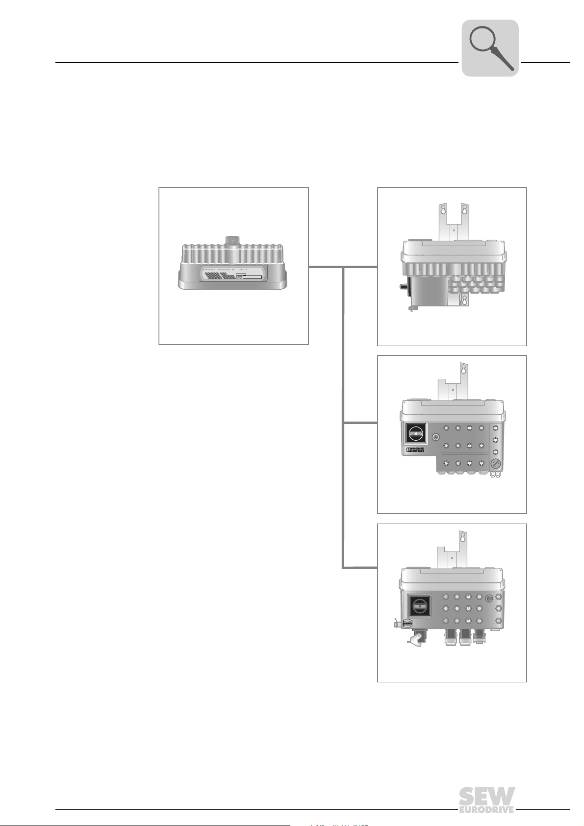
4.1 Overview
The following figure depicts the MOVIFIT® versions described in these operating
instructions:
Unit Design
Overview
4
EBOX (active electronics unit)
MTS...-....-00
BUS-F
SYS-F
24V-S
24V-C
RUN
DI01
DI03
DI02
DI00
DI07
DI06
DI05
DI04
MOVIFIT® SC
with integrated motor starter
RUN-PS
DI11
DI12/DO00
DI08
DI10
DI09
DI15/Do03
DI14/DO02
DI13/DO01
MOVIFIT
®
ABOX (passive connection unit)
MTA...-S02.-...-00
Connection box with terminals and
cable glands
MTA...-S12.-...-00
MTA...-S22.-...-00
Hybrid connection box
with terminals and
M12 plug connector
MTA...-H12.-...-00
MTA...-H22.-...-00
HanModular® connection box with
HanModular
M12 plug connector
®
plug connector and
61127AEN
Operating Instructions – MOVIFIT® SC
11
4
Unit Design
EBOX (active electronics unit)
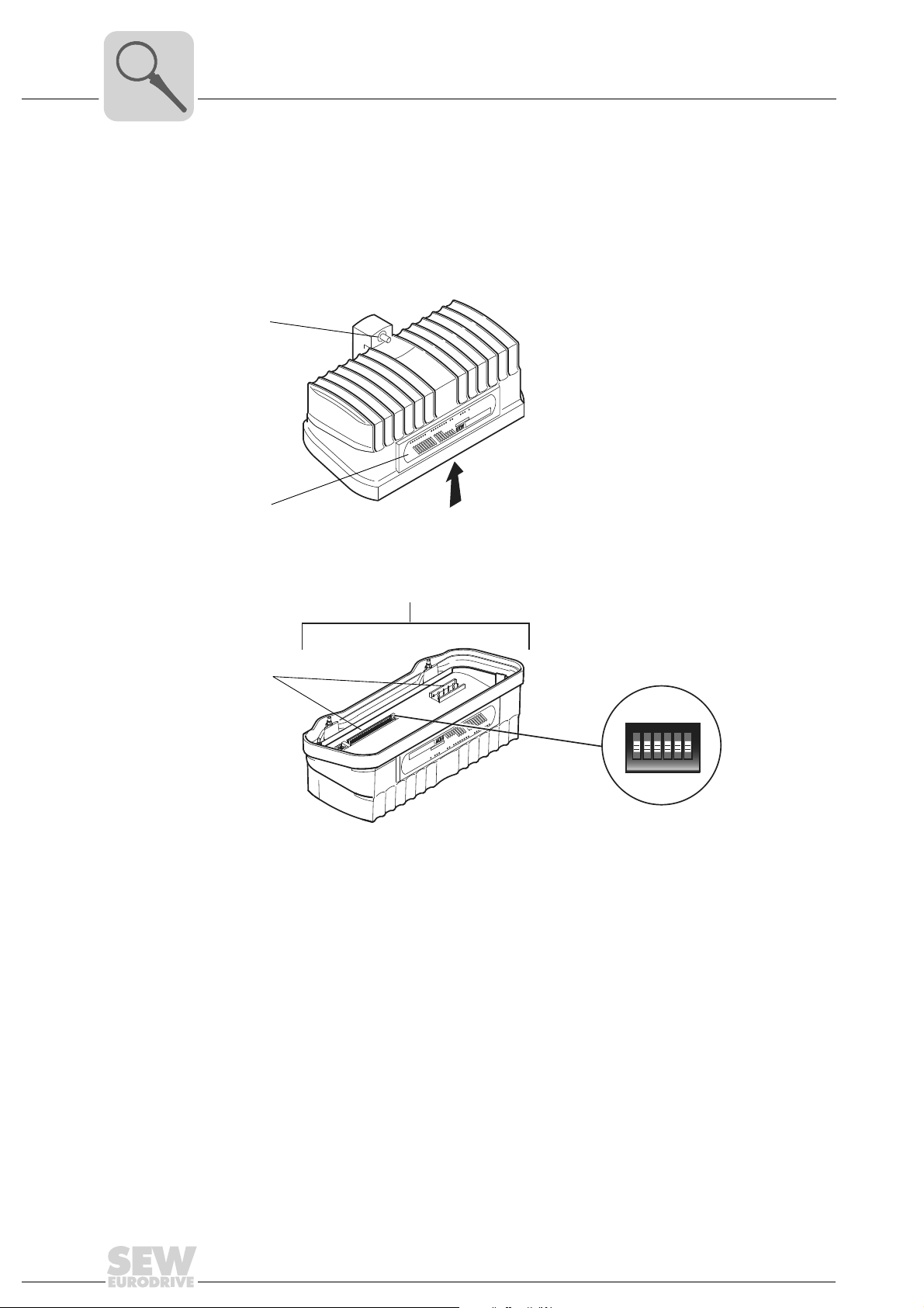
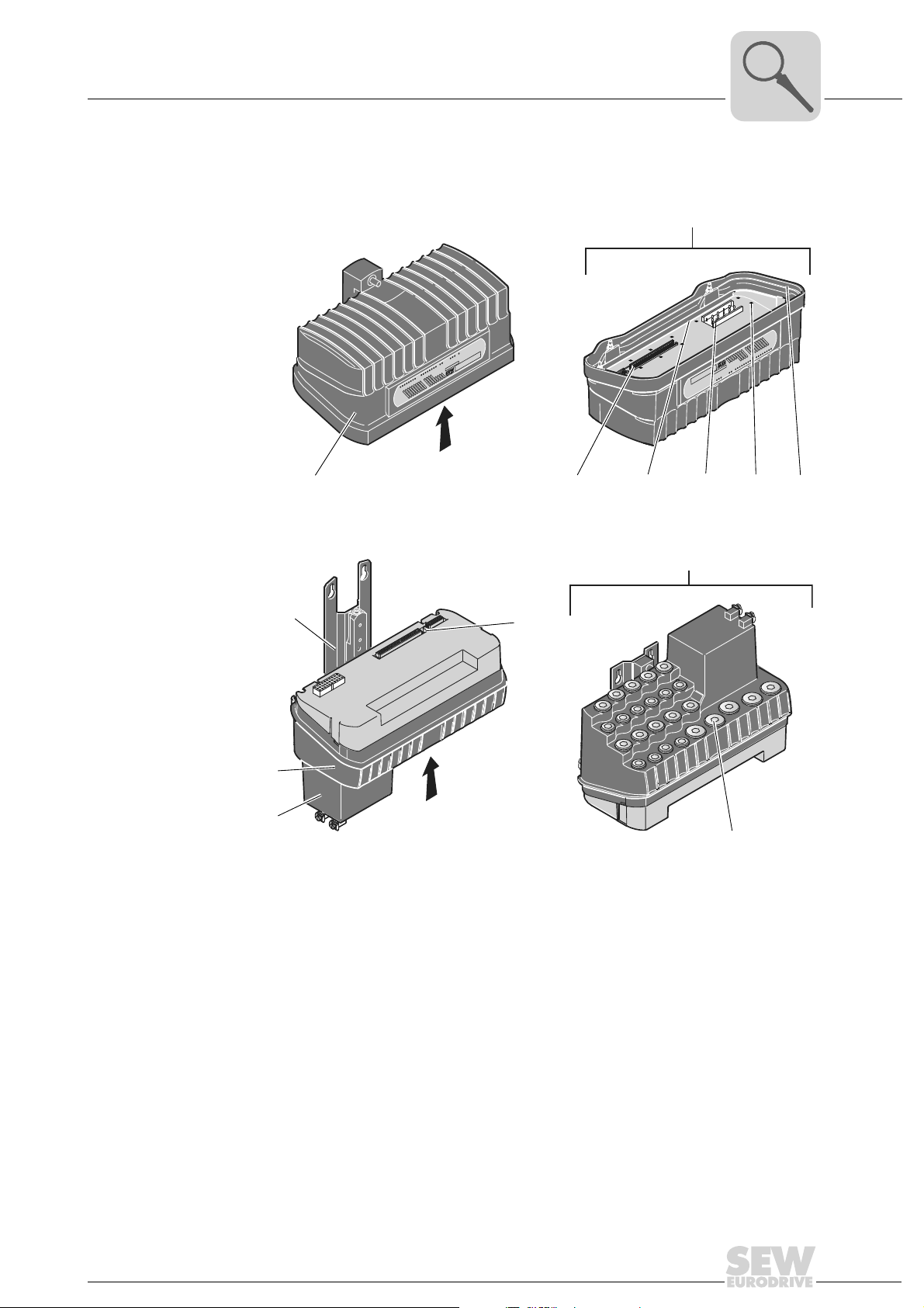
4.2 EBOX (active electronics unit)
The MOVIFIT® SC EBOX is a closed electronics unit with communication interface,
I/Os, and motor starter:
[1]
[2]
[3]
EBOX "
MTS...-....-00"
DI15/Do03
DI14/DO02
DI13/DO01
DI12/DO00
DI11
DI10
DI09
DI08
DI07
DI06
DI05
DI04
DI03
DI02
DI01
DI00
X
®
RUN-PS
MOVIFIT
RUN
24V-S
24V-C
BUS-F
SYS-F
X
[4]
DI00
DI01
DI02
DI03
DI04
DI05
DI06
DI07
DI08
DI09
DI11
DI12/DO00
DI13/DO01
DI14/DO02
DI15/Do03
SYS-F
BUS-F
24V-C
24V-S
RUN
MOVIFIT
RUN-PS
®
S10
ON
123456
[1] Central opening/closing mechanism
[2] Operation LEDs for I/Os (can be labeled), communication, and unit status
[3] Connection to connection box
[4] DIP switch S10 for unit functions
61128AXX
12
Operating Instructions – MOVIFIT® SC
ABOX (passive connection unit)
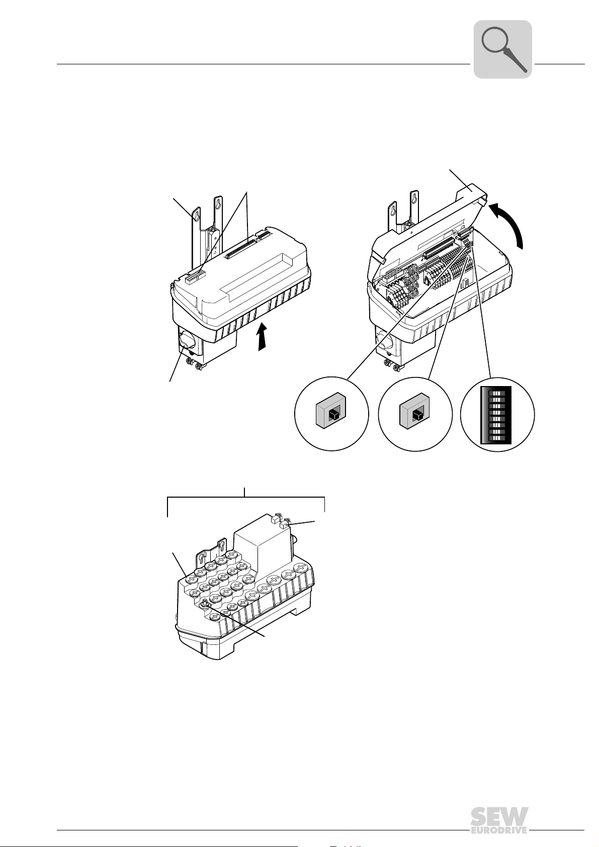
4.3 ABOX (passive connection unit)
4.3.1 ABOX with terminals and cable glands "MTA...-S02.-...-00"
The following figure depicts the MOVIFIT
®
ABOX with terminals and cable glands:
Unit Design
4
[1]
[4]
ABOX "MTA...-S02.-...-00"
[2]
X
S1
S3
[3]
S2
ON
12345678
[5]
[6]
X
[9]
[8]
[10]
[1] Mounting rail
[2] Connection to EBOX
[3] Protection cover
[4] Maintenance switch
[5] DIP switch S1 for bus termination (PROFIBUS version only)
[6] DIP switch S3 for bus termination SBus
[7] DIP switch S2 for bus address (PROFIBUS and DeviceNet version only)
[8] Diagnostic interface under the screw fitting
[9] Grounding screws
[10] Micro-style connector (DeviceNet version only)
[7]
61091AXX
Operating Instructions – MOVIFIT® SC
13
4
Unit Design
ABOX (passive connection unit)
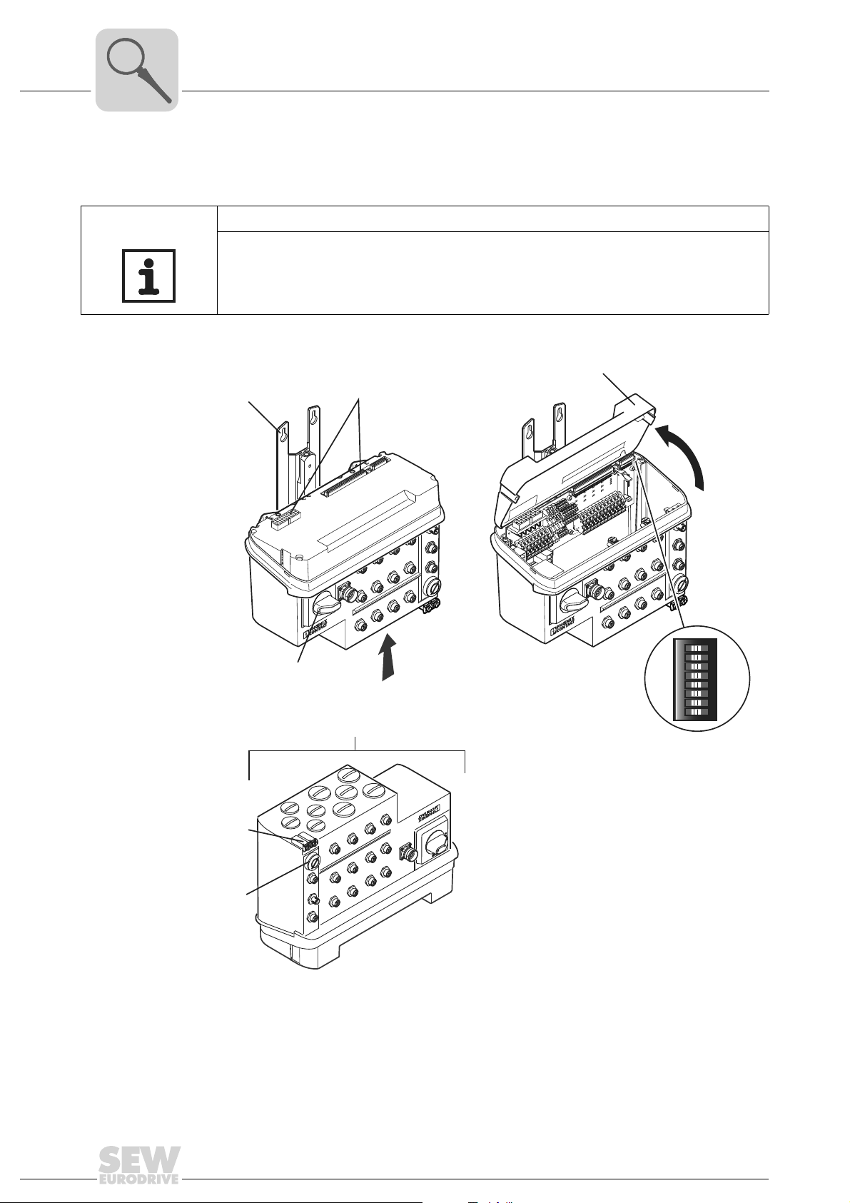
4.3.2 Hybrid ABOX "MTA...-S12.-...-00" and "MTA...-S22.-...-00"
The following figure depicts the MOVIFIT
tions, terminals, and cable glands:
NOTE
The following depicts the connection technology of the PROFIBUS version as an
example: For detailed information about additional variants, refer to the section "Installation".
ABOX "MTA...-S12.-...-00" / "MTA...-S22.-...-00"
®
hybrid ABOX with M12 SPEEDCON connec-
[3]
[1]
[4]
[2]
12
X
X14
7 X28
2
X
50
26
X
9
X1
5
X2
0OFF
X42
X41
X
44
X
43
X
0OFF
6
X2
X19
X25
42
X
41
X
X12
8
14
X2
X
27
X
0
X5
4
X4
43
X
[5]
ON
12345678
S2
X
X
14
[6]
[7]
61092AXX
[1] Mounting rail
[2] Connection to EBOX
[3] Protection cover
[4] Maintenance switch
[5] DIP switch S2 for bus address (PROFIBUS and DeviceNet version only)
[6] Grounding screws
[7] Diagnostic interface under the screw fitting
Operating Instructions – MOVIFIT® SC
ABOX (passive connection unit)
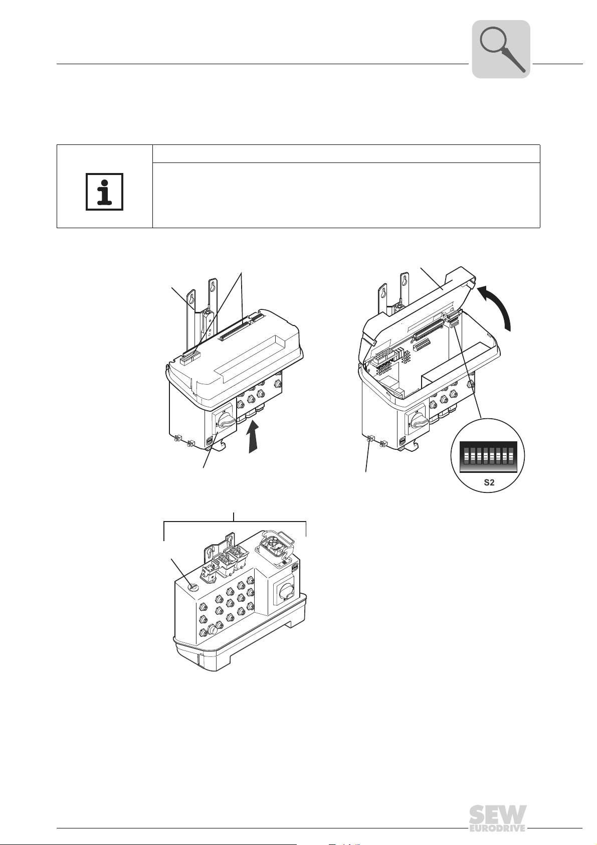
4.3.3 HanModular® ABOX "MTA...-H12.-...-00" and "MTA...-H22.-...-00"
®
The following figure depicts the HanModular
connection box with HanModular® plug
connector and M12 plug connector:
NOTE
The following depicts the connection technology of the PROFIBUS version as an
example: For detailed information about additional variants, refer to the section "Installation".
ABOX "MTA...-H12.-...-00" / "MTA...-H22.-...-00"
[2]
[1]
Unit Design
[3]
4
X
[4]
[5]
X
[7]
[1] Mounting rail
[2] Connection to EBOX
[3] Protection cover
[4] Maintenance switch
[5] Grounding screws
[6] DIP switch S2 for bus address (PROFIBUS and DeviceNet version only)
[7] Diagnostic interface under the screw fitting
[6]
ON
12345678
61043AXX
Operating Instructions – MOVIFIT® SC
15
4
Unit Design
Hygenicplus version (optional)
4.4 Hygenic
4.4.1 Features
plus
version (optional)
The Hygenic
• IP66 in accordance with EN 60529 and IP69K according to DIN 40050-9 (MOVIFIT
housing closed and all cable glands sealed according to the relevant enclosure)
• Easy-to-clean housing (self-draining design)
• Surface with anti-adhesive properties
• High impact resistance of the surface against mechanical damage
• Compatibility with cleansing agents having the following properties:
– Alkaline
– Acidic
– Disinfectant
Do not mix cleaning and disinfecting agents under any circumstances.
Never mix acids and chloralkalis, as poisonous chlorine gas will result.
Strictly observe the safety instructions of the cleaning agent manufacturer.
• Resistant to temperature fluctuations
• Resistant to condensation caused by coated connection boards
plus
version has the following characteristics:
NOTES
®
The Hygenic
and cable glands "MTA12…-S02.-…-00".
For additional features of the Hygenic
plus
version is only available in conjunction with the ABOX with terminals
plus
version, refer to the section "Technical Data".
16
Operating Instructions – MOVIFIT® SC
Unit Design
Hygenicplus version (optional)
4
The following figure depicts the additional features of MOVIFIT® units in the optional
plus
Hygenic
EBOX "
version:
MTS12...-....-00"
DI04
DI03
DI02
DI01
DI00
X
DI00
®
RUN-PS
MOVIFIT
RUN
24V-S
24V-C
BUS-F
SYS-F
DI15/Do03
DI14/DO
DI13/DO01
DI12/DO
DI11
02
DI10
DI09
00
DI08
DI07
DI06
DI05
24V-C
24V-S
RUN
MOVIFIT
RUN-PS
®
DI01
DI02
DI03
DI04
DI05
DI06
DI07
DI08
DI09
DI11
DI12/DO00
DI13/DO01
DI14/DO02
DI15/Do03
SYS-F
BUS-F
X
[1] [2] [4] [6]
[3]
[5]
ABOX "MTA12...-S02.-...-00"
Y
[7]
[8]
[9]
[10]
[1] EBOX with special surface treatment (only available in one color)
[2] Signal plug connector with gasket
[3] Gasket between ABOX and coverplate
[4] Power plug connector with gasket
[5] Screws with thread sealant
[6] Replaceable profile seal
[7] Mounting rail with
[8] Connection board with increased resistance to moisture condensation (
[9] ABOX with special surface treatment (only available in one color)
[10] In conjunction with Hygenic
[11] Stainless steel screw plugs (optionally available)
Y
special surface treatment (only available in one color)
plus
version: Generally without maintenance switch
[11]
61158AXX
with special surface treatment)
Operating Instructions – MOVIFIT® SC
17
4
Unit Design
Unit designation MOVIFIT® SC
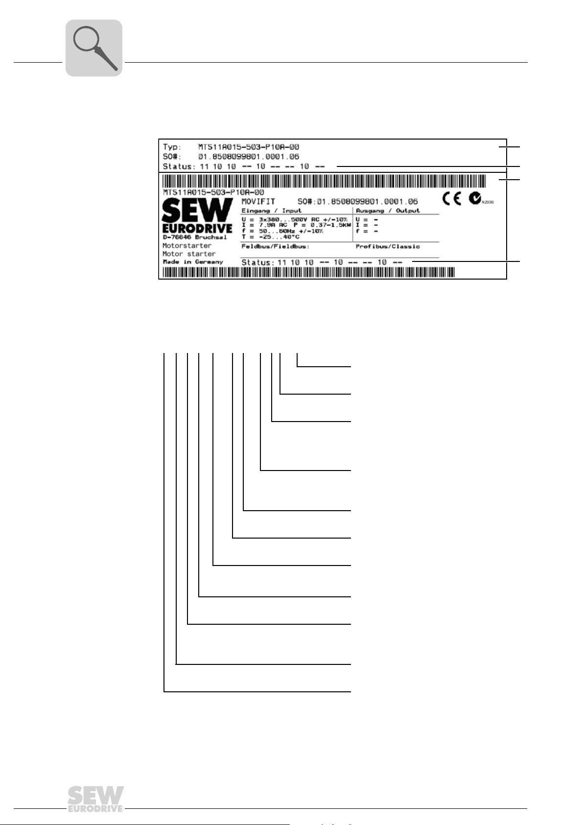
4.5 Unit designation MOVIFIT® SC
Example EBOX
nameplate
[A] External nameplate
[B] Inner nameplate
[1] EBOX status field
[A]
[1]
[B]
[1]
61160AXX
MT S 11 A 015- 50 3 - P1 0 A - 00
EBOX version
00 = Series
A = Version
Function level
0 = Classic
1 = Technology
2 = System
Fieldbus
P1 = PROFIBUS
D1 = DeviceNet
E2 = PROFINET
Connection type
3 = 3-phase
Connection voltage
50 = AC 380...500 V
Unit power
015= 1.5 kW
040 = 4.0 kW
Version A
Series
11 = Standard
12 = Hygenic
plus
version
18
Unit type
S = MOVIFIT
MT = MOVIFIT
®
SC (motor starter)
®
unit series
Operating Instructions – MOVIFIT® SC
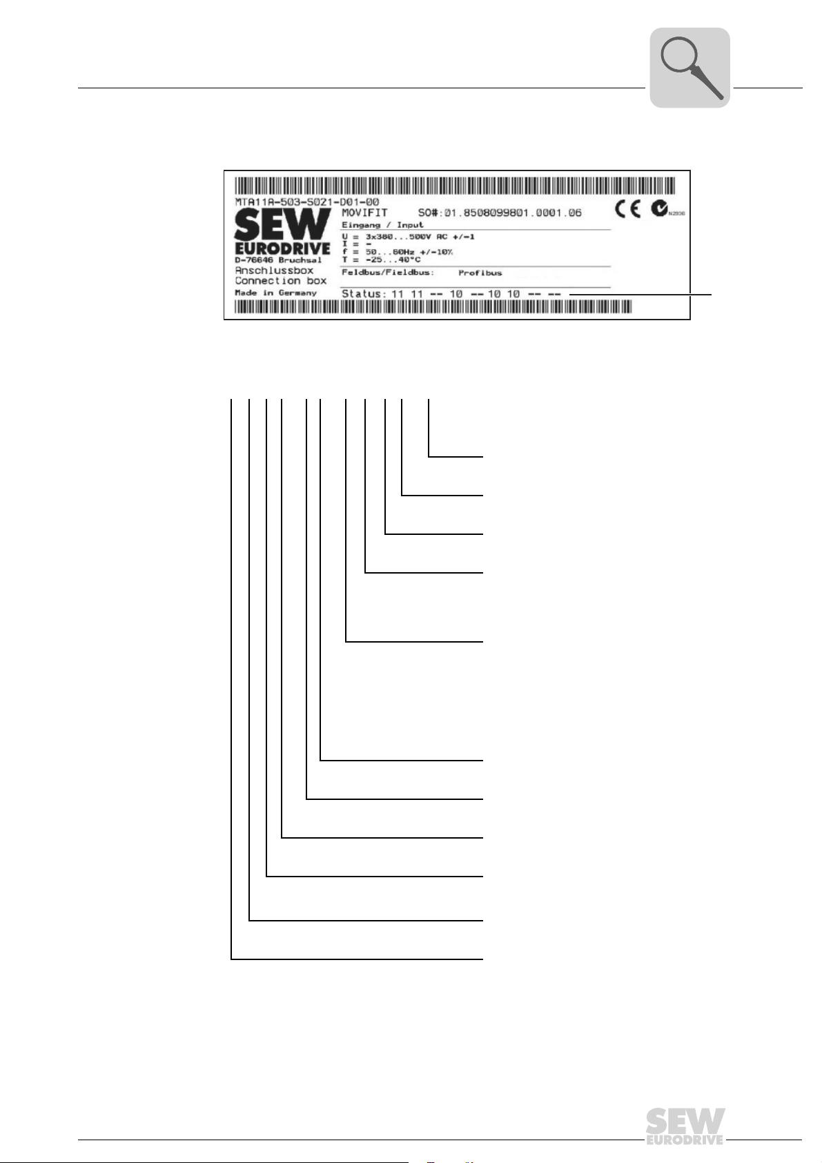
Example ABOX
nameplate
Unit designation MOVIFIT® SC
[1] ABOX status field
MT A 11 A - 50 3 -S02 1 - D 01 - 00
Unit Design
ABOX version
00 = Series
4
[1]
61154AXX
Maintenance switch type
01 = With rotary button (ABB)
Maintenance switch type
D = Switch disconnector
Fieldbus
1 = PROFIBUS
2= DeviceNet
3 = Ethernet
Connection configuration
S02 = Connection box with terminals
S12/S22 = Hybrid connection box
H12/H22 = HanModular
Connection type
3 = 3-phase (AC)
Connection voltage
50 = 380 V to 500 V
A = Version
Series
11 = Standard
12 = Hygenic
Unit type
A = Connection box
and cable glands
with terminals and
M12 plug connector
with HanModular
and M12 plug connector
plus
version
®
connection box
®
Operating Instructions – MOVIFIT® SC
MT = MOVIFIT
®
unit series
19
5
Mechanical Installation
Installation instructions
5 Mechanical Installation
5.1 Installation instructions
• Mount MOVIFIT® only on a level, vibration-proof and torsionally rigid support
structure, as described in the section "Approved installation position".
• Use suitable fittings for the cables (use reducing adapters if necessary). With
connector plug versions, you must use a suitable mating connector.
• Use screw plugs to seal cable entries not in use.
• Use protective caps to plug connectors not in use.
5.2 Approved installation position
The following figure depicts the approved installation position for MOVIFIT®.
MOVIFIT
installed in the mounting surface. See page 21 for more information.
®
is attached by means of a mounting platform using the four screws already
20
58822AXX
NOTE
In this section, the version with terminals and cable glands will be illustrated as an
example. However, the installation notes are applicable for all versions.
Operating Instructions – MOVIFIT® SC
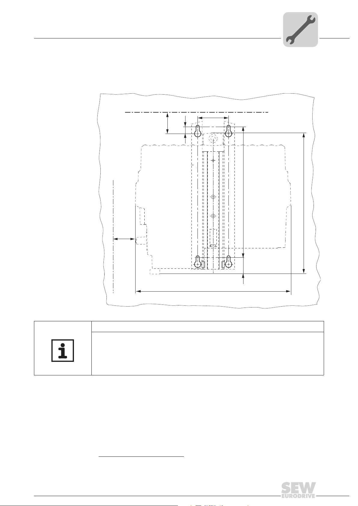
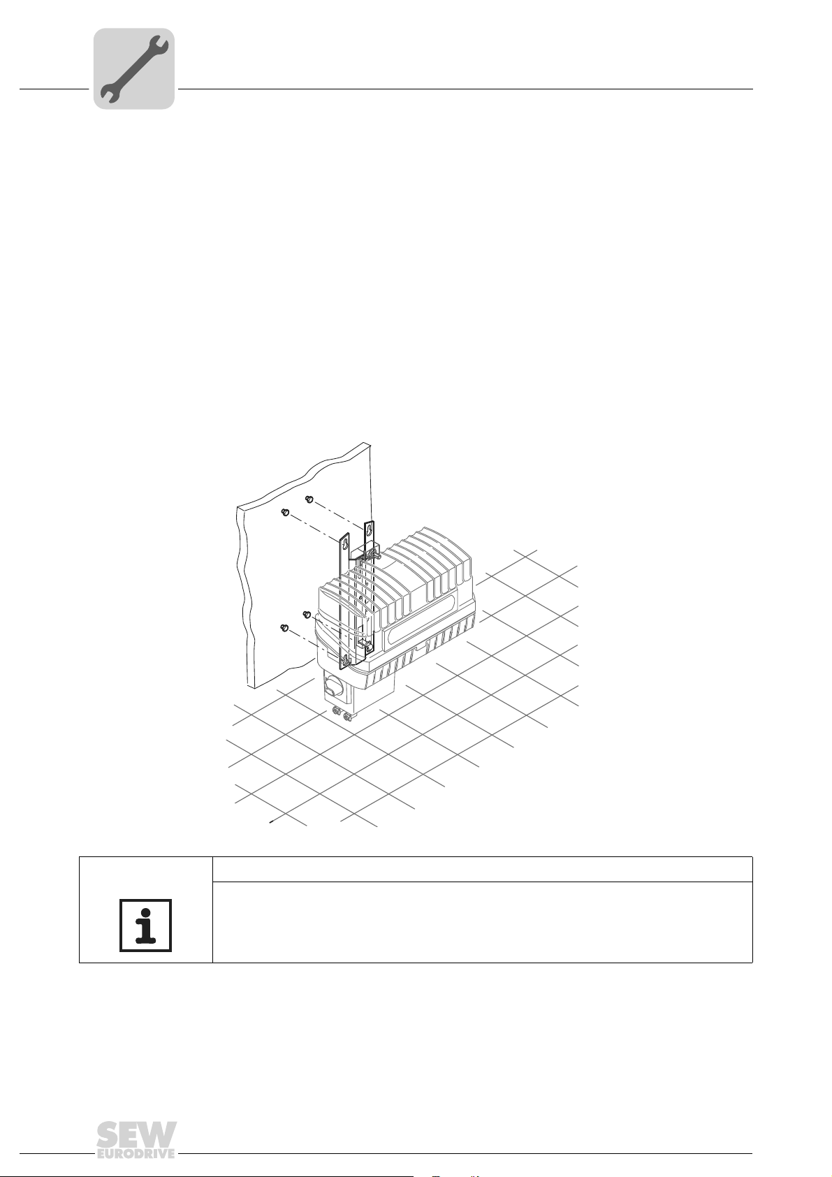
5.3 Installation notes
1. Drill holes for mounting the four screws1) to the mounting surface according to the
following figure:
Mechanical Installation
Installation notes
5
[1]
min. 50
min. 40
66
15
280
303.5
37,9
334.5
[2]
61182AXX
NOTES
• [1] Note the minimum installation clearance so that the EBOX can be removed from
the ABOX.
• [2] Note the minimum installation clearance required to operate the maintenance
switch and to ensure heat dissipation for the unit.
Refer to page 132 ff. for detailed dimension drawings.
1) We recommend screws of size M6 and dowel pins, if necessary.
Operating Instructions – MOVIFIT® SC
21
5
Mechanical Installation
Installation notes
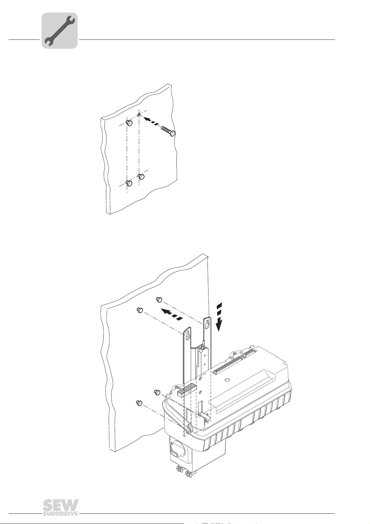
2. Insert four screws into the mounting surface. We recommend size M6 screws and
depending on the base, dowel pins, if necessary.
57136AXX
3. Mount ABOX with mounting platform on screws.
1.
2.
22
61386AXX
Operating Instructions – MOVIFIT® SC
Mechanical Installation
Installation notes
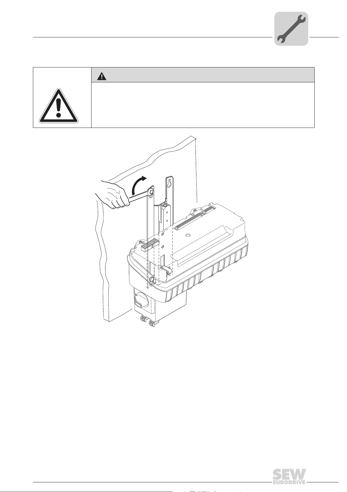
4. Tighten the screws
CAUTION!
Hazard from falling load
Minor injuries
• You will have to tighten at least the upper two of the four wall screws to ensure a
secure fit after mounting.
5
Operating Instructions – MOVIFIT® SC
59559AXX
23
5
Mechanical Installation
Central opening/closing mechanism
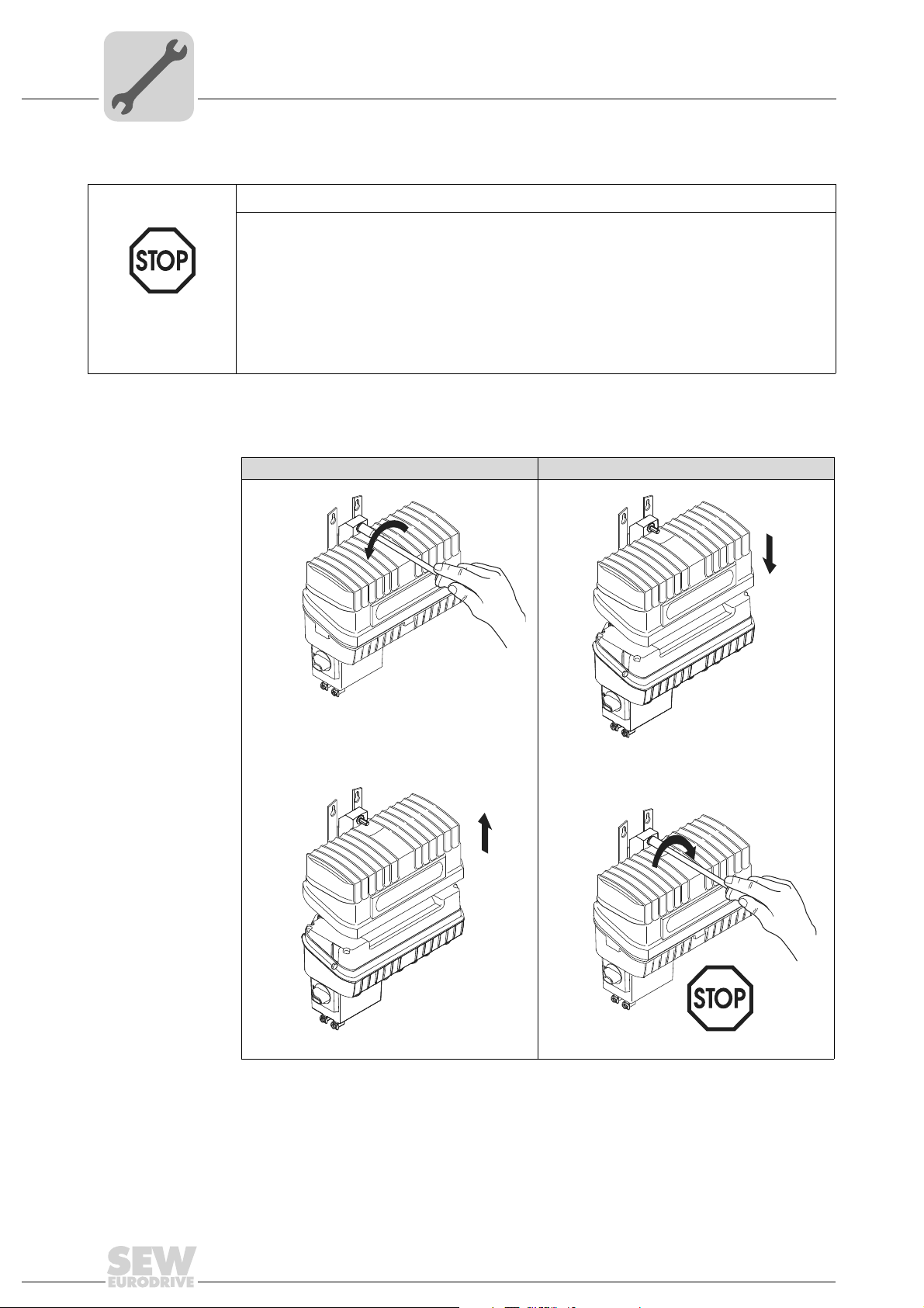
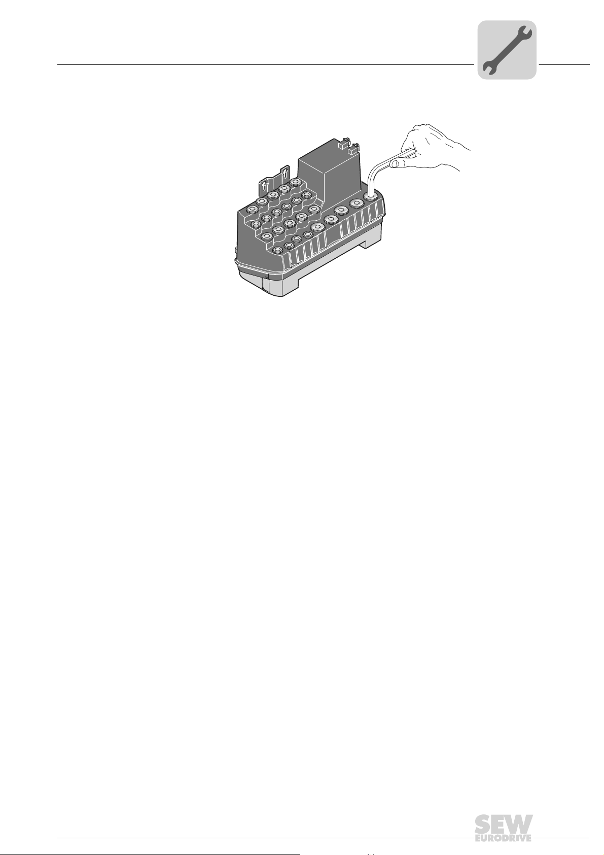
5.4 Central opening/closing mechanism
STOP!
If the torque is too high, the central opening/closing mechanism can be destroyed.
• It is essential that you do not exceed a maximum torque of 7 Nm when closing.
5.4.1 Operation
The enclosure specified in the technical data only applies when a unit is mounted
correctly. The MOVIFIT
®
may be damaged by moisture or dust when the EBOX is
removed from the ABOX.
• Protect ABOX and EBOX for when the unit is open.
A socket wrench (SW8) is required for the central retaining screw.
Open Close
1.
ABOX
EBOX
EBOX
1.
ABOX
24
ABOX
2.
EBOX
58936AXX
2.
ABOX
Operating Instructions – MOVIFIT® SC
EBOX
max.
7 Nm!
61071AXX
Mechanical Installation
Central opening/closing mechanism
5
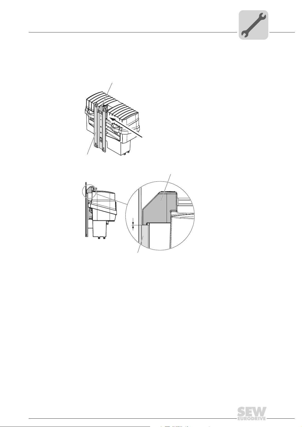
5.4.2 Notes on closing the MOVIFIT
The MOVIFIT® is closed correctly when the redirector of the closing mechanism [2] is
on the mounting plate [1].
[2]
[1]
Z
®
Z
[2]
0
[1]
60932AXX
Operating Instructions – MOVIFIT® SC
25
5
Mechanical Installation
Tightening torques
5.5 Tightening torques
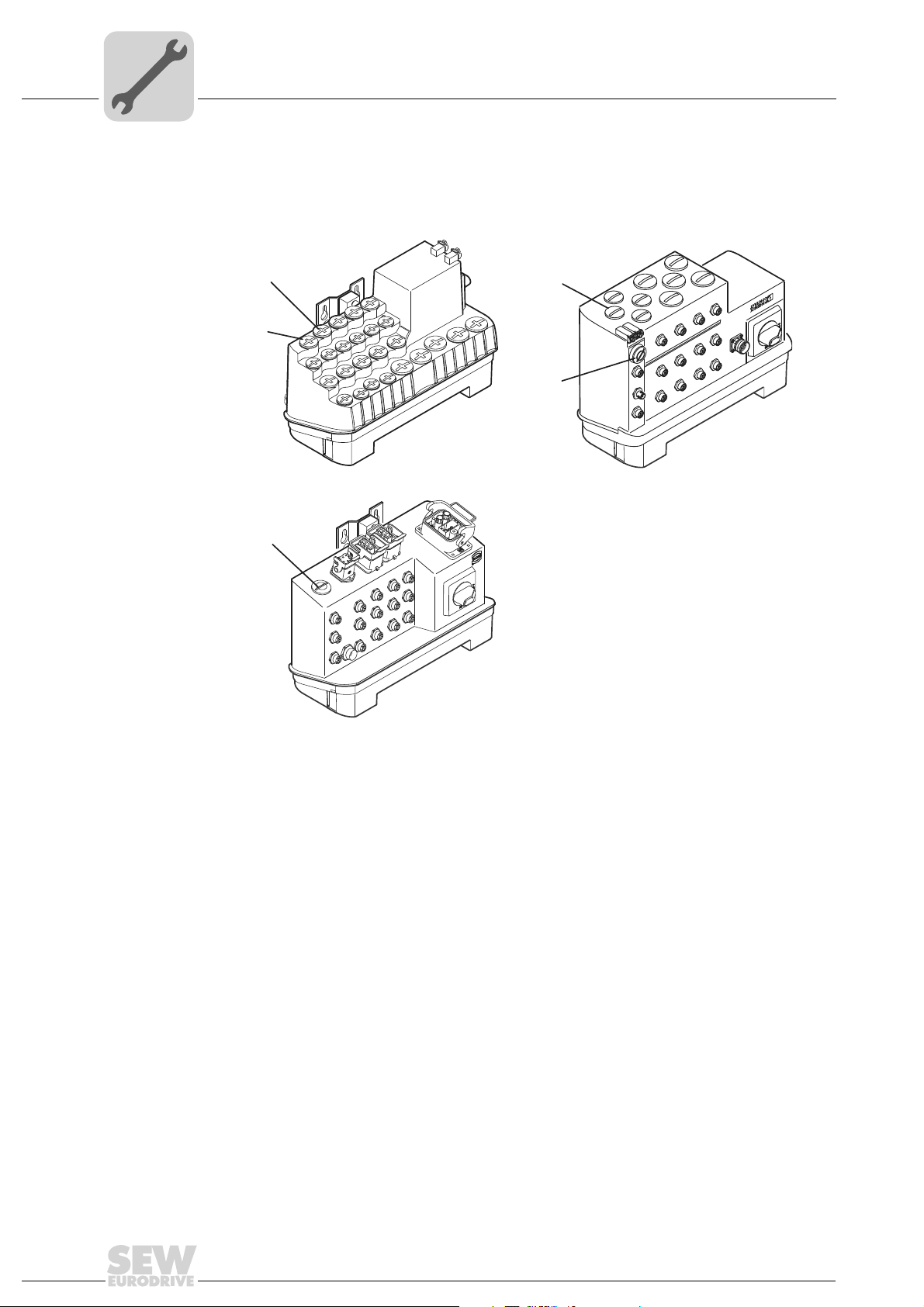
Ensure a tightening torque of 2.5 Nm for the blanking plugs [1] supplied by SEWEURODRIVE and the screw plug using the diagnostic interface [2]:
[2]
[1]
[2]
[1]
[2]
[1] Blanking plug cable entry
[2] Diagnostic interface screw plug
61148AXX
26
Operating Instructions – MOVIFIT® SC
Mechanical Installation
DI03
DI01
DI02
DI00
DI04
DI05
DI06
DI07
DI08
DI09
DI10
DI11
DI12/DO00
DI13/DO01
DI14/DO02
DI15/Do03
SYS-F
BUS-F
24V-C
24V-S
RUN
RUN-PS
MOVIFIT
®
Hygenicplus version
5
5.6 Hygenic
plus
version
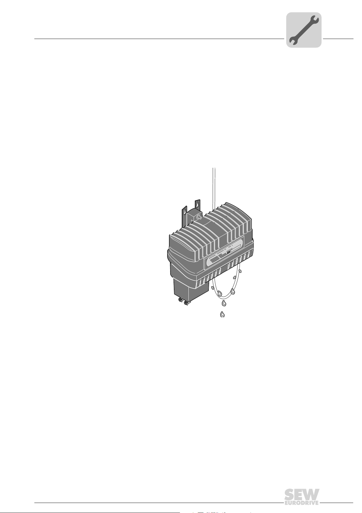
5.6.1 Installation notes
• Close the unit during extended breaks in installation to prevent humidity or dirt from
• After electrical installation and during assembly, check for damaged seals and
• Check the state of the profile seal in the EBOX when performing maintenance.
• Use only cable glands or screw plugs that correspond with the enclosure. Glands and
• Make sure to install the cable with a drip loop; see the following figure:
entering.
sealing surfaces.
In case of damage, contact SEW-EURODRIVE.
screw fittings available from SEW EURODRIVE can be found in the section "Technical Data" on page 131.
• You must seal unused cable glands and plug connectors with suitable screw plugs,
see page 131.
Operating Instructions – MOVIFIT® SC
60893AXX
27
5
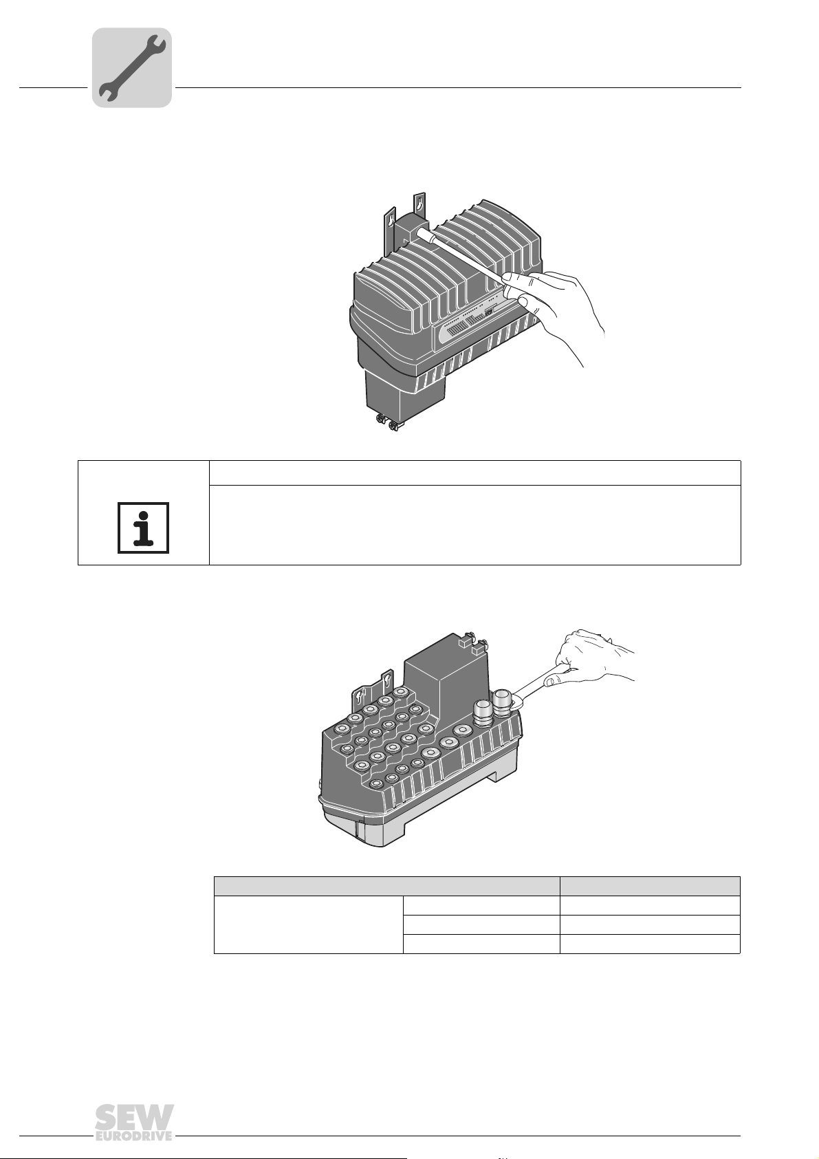
5.6.2 Tightening torques
Mechanical Installation
Hygenicplus version
Central opening/closing
mechanism
The permitted tightening torque for the central opening/closing mechanism is 7 Nm.
®
RUN-PS
MOVIFIT
RUN
24V-S
24V-C
BUS-F
SYS-F
DI15/Do03
DI14/DO02
DI13/DO01
DI12/DO00
DI11
DI10
DI09
DI08
DI07
DI06
DI05
DI04
DI03
DI02
DI01
DI00
60904AXX
NOTE
Also observe the notes in the section "Central opening/closing mechanism" starting on
page 24.
EMC cable glands Observe the permitted tightening torque in the table for EMC cable glands:
Screw fitting Tightening torque
EMC cable glands M16 x 1.5 3.0 Nm to 4.0 Nm
M20 x 1.5 3.5 Nm to 5.0 Nm
M25 x 1.5 4.0 Nm to 5.5 Nm
The cable retention in the cable gland must withstand the following removal force of the
cable from the cable gland:
• Cable with outer diameter > 10 mm: Ã 160 N
• Cable with outer diameter < 10 mm: = 100 N
60908AXX
28
Operating Instructions – MOVIFIT® SC
Mechanical Installation
Hygenicplus version
Blanking plugs The permitted tightening torque for blanking plugs is 2.5 Nm:
5
60902AXX
Operating Instructions – MOVIFIT® SC
29
6
Electrical Installation
Installation planning with regard to EMC issues
6 Electrical Installation
6.1 Installation planning with regard to EMC issues
Successful installation of decentralized drives depends on selecting the correct cables,
providing correct grounding and a functioning equipotential bonding.
The relevant standards must be applied in all cases. You also need to consider the
following points:
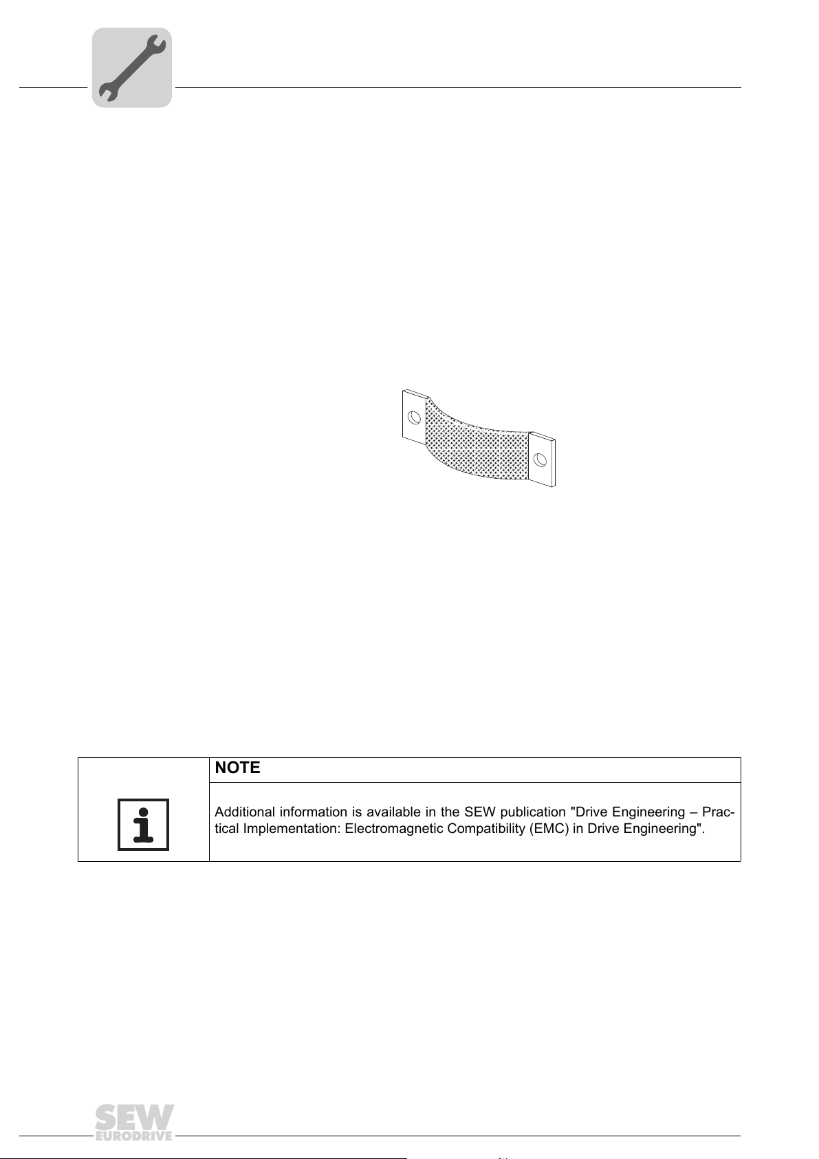
• Equipotential bonding
– Regardless of the protective earth connection, it is essential that low-impedance,
HF-capable potential compensation is provided (see also VDE 0113 or VDE 0100
part 540); e.g. by
– Flat contact surface connection of metal (system) components
– Using flat grounding strips (HF litz wire)
03643AXX
– Do not use the cable shield of data cables for equipotential bonding.
• Data cables and 24 V supply
– Must be routed separately from cables subject to interference (e.g. control cables
from solenoid valves, motor cables).
• Connection between MOVIFIT
– We recommend using pre-fabricated SEW hybrid cables especially designed for
the connection of MOVIFIT
®
and motor
®
units and motors.
• Cable shields
– Must have good EMC characteristics (high shield attenuation).
– May not serve only as mechanical protection for the cable.
– Must be connected to a wide area of the unit's metal housing at the cable ends
(see also 37 and page 38).
NOTE
Additional information is available in the SEW publication "Drive Engineering – Practical Implementation: Electromagnetic Compatibility (EMC) in Drive Engineering".
30
Operating Instructions – MOVIFIT® SC
 Loading...