

SEW MOVIFIT-SC, MOVIFIT-FC, MOVIFIT-MC User Manual

Gearmotors \ Industrial Gear Units \ Drive Electronics \ Drive Automation \ Services
®
MOVIFIT
Function Level
Edition 05/2007
11591811 / EN
"
Classic
"
M
anual

SEW-EURODRIVE – Driving the world

Contents
1 General Notes .................................................................................................... 5
1.1 Structure of the safety notes ..................................................................... 5
1.2 Right to claim under warranty ................................................................... 5
1.3 Exclusion of liability ................................................................................... 5
1.4 Applicable documents............................................................................... 6
1.5 General safety notes for bus systems....................................................... 6
1.6 Safety functions ........................................................................................ 6
1.7 Hoist applications...................................................................................... 6
2 Index of Changes .............................................................................................. 7
2.1 Changes to the previous version............................................................... 7
3 Introduction ....................................................................................................... 8
3.1 MOVIFIT
®
function level ........................................................................... 8
3.2 "Classic" function level .............................................................................. 8
4 Startup................................................................................................................ 9
4.1 Startup procedure for MOVIFIT
4.2 Startup procedure for MOVIFIT
®
-MC........................................................ 9
®
-SC and -FC ........................................ 10
5 PROFIBUS........................................................................................................ 11
5.1 Project planning for the PROFIBUS master............................................ 11
5.2 Project planning for MOVIFIT
®
-Classic................................................... 16
5.3 Parameter setting using PROFIBUS-DPV1 ............................................ 23
6 PROFINET IO ................................................................................................... 32
6.1 Project planning for the PROFINET IO controller ................................... 32
6.2 Assigning the PROFINET IO unit name.................................................. 34
6.3 Project planning for MOVIFIT
®
-Classic................................................... 36
6.4 PROFINET diagnostic alarms................................................................. 43
7 DeviceNet ......................................................................................................... 46
7.1 Installing the EDS file via RSNetworx ..................................................... 46
7.2 Project planning for MOVIFIT
®
-Classic................................................... 48
7.3 Parameter setting via DeviceNet............................................................. 60
8 Process Data Description............................................................................... 64
8.1 Process image for diagnostics ................................................................ 64
8.2 Process image for digital I/Os ................................................................. 66
8.3 Process image of drive systems ............................................................. 69
9 Fault Responses.............................................................................................. 83
9.1 Fieldbus timeout ..................................................................................... 83
9.2 System fault (SYS-F) .............................................................................. 84
10 Parameter Setting and Diagnostics............................................................... 85
10.1 MOVITOOLS
10.2 Motor/brake startup with MOVIFIT
10.3 Motor/brake startup with MOVIFIT
10.4 Hoist startup with MOVIFIT
10.5 Parameter list for the MOVIFIT
10.6 Parameter description for MOVIFIT
10.7 Parameter list for the MOVIFIT
10.8 Parameter description for MOVIFIT
10.9 Web diagnostics for Ethernet units ....................................................... 126
Manual – MOVIFIT® Function Level "Classic"
®
Motion Studio ................................................................. 85
®
®
-SC.................................................. 88
®
-FC.................................................. 91
-FC in "Expert mode" ................................. 99
®
-SC power section.............................. 100
®
-SC.............................................. 103
®
-FC power section.............................. 113
®
-FC .............................................. 117
3

Contents
11 Technical Data ............................................................................................... 132
11.1 PROFIBUS interface ............................................................................. 132
11.2 MOVIFIT
11.3 PROFINET interface ............................................................................. 133
11.4 DeviceNet interface............................................................................... 133
12 Index ............................................................................................................... 134
®
module IDs and configuration data for PROFIBUS............. 132
4
Manual – MOVIFIT® Function Level "Classic"
General Notes
Structure of the safety notes
1 General Notes
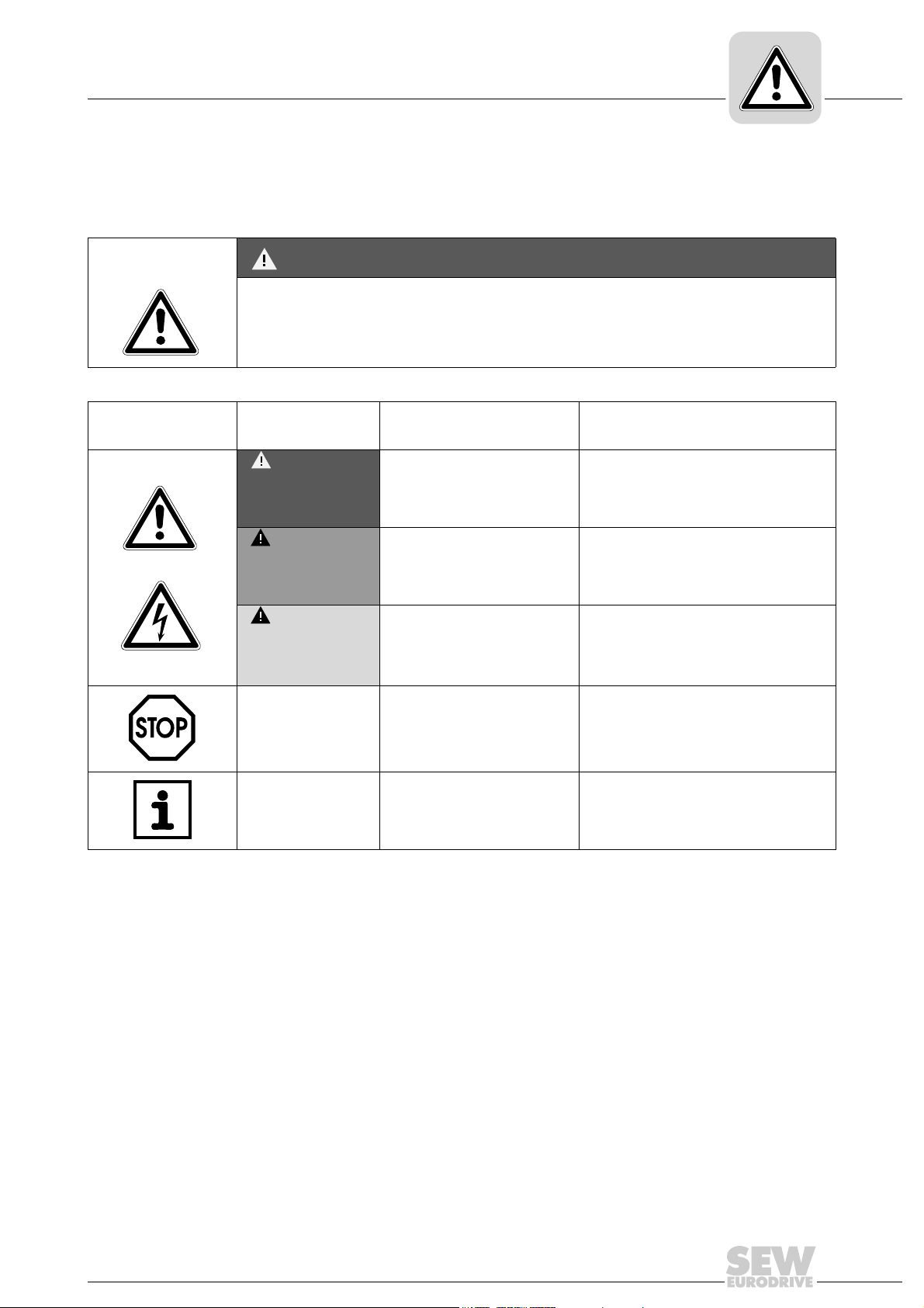
1.1 Structure of the safety notes
The safety notes in these operating instructions are structured as follows:
Symbol SIGNAL WORD
Nature and source of hazard.
Possible consequence(s) if disregarded.
• Measure(s) to avoid the hazard.
Symbol Signal word Meaning Consequences if
disregarded
Example:
DANGER Imminent danger Severe or fatal injuries
1
WARNING Possible hazardous situation Severe or fatal injuries
General hazard
CAUTION Possible hazardous situation Minor injuries
Specific hazard,
e.g. electric shock
STOP Possible damage to property Damage to the drive system or its
NOTE Useful information or tip.
Simplifies handling of the drive
system.
1.2 Right to claim under warranty
As a prerequisite to fault-free operation and fulfillment of warranty claims, you must
adhere to the information in the MOVIFIT
tions before you start working with the unit.
Make sure that the operating instructions are legible and available to persons responsible for the plant and its operation, as well as to persons who work independently on
the unit.
environment
®
documentation. Read the operating instruc-
1.3 Exclusion of liability
You must comply with the information contained in the MOVIFIT® documentation to
ensure safe operation of MOVIFIT
mance features. SEW-EURODRIVE assumes no liability for injury to persons or
damage to equipment or property resulting from non-observance of these operating
instructions. In such cases, any liability for defects is excluded.
Manual – MOVIFIT® Function Level "Classic"
®
and to achieve the specified product and perfor-
5

1
General Notes
Applicable documents
1.4 Applicable documents
• This manual does not replace the detailed operating instructions.
• Only qualified personnel observing all applicable accident prevention guidelines and
the MOVIFIT
version in use) operating instructions may install and take these units into operation.
®
-MC, MOVIFIT®-SC or MOVIFIT®-FC (depending on the MOVIFIT
1.5 General safety notes for bus systems
You are now in possession of a communication system that lets you adapt MOVIMOT
and MOVIFIT® frequency inverters and MOVIFIT® motor starters to the particulars of
your system. As with all bus systems, there is a danger of invisible, external (as far as
the inverter/motor starter is concerned) modifications to the parameters which give rise
to changes in the inverter/motor starter behavior. This may result in unexpected (not
uncontrolled) system behavior.
1.6 Safety functions
®
®
MOVIFIT® may not perform any safety functions unless they are described and
expressly approved.
For safety applications, ensure that the information in the following publication is
observed.
• Safe disconnection for MOVIFIT
Use only those components in safety applications that were explicitly designed and
delivered for this purpose by SEW-EURODRIVE.
1.7 Hoist applications
• Hoist applications can only be implemented with MOVIFIT®-FC in combination with
the "Classic" function level under the following conditions:
– A hoist startup must be performed.
• MOVIFIT
Use monitoring systems or mechanical protection devices as safety equipment to
avoid possible damage to property or injury to people.
®
®
-FC is not designed for use as a safety device in hoist applications.
6
Manual – MOVIFIT® Function Level "Classic"

2 Index of Changes
2.1 Changes to the previous version
The following section lists the main changes made to the individual sections from the
06/2006 edition, part number 11461012 (EN).
Index of Changes
Changes to the previous version
2
"PROFINET IO"
section
"Device Net"
section
"Parameter
Setting and
Diagnostics"
section
"Technical Data"
section
• New section "Project planning for the PROFINET IO controller"
• New section "Assigning the PROFINET IO unit name"
• New section "Project Planning for MOVIFIT
• New section "PROFINET diagnostic alarms"
• New section "Installing the EDS file via RSNetworx"
• New section "Project Planning for MOVIFIT
• New section "Parameter setting via DeviceNet"
• New section "MOVITOOLS
• New section "Web diagnostics for Ethernet units"
• New section "PROFINET interface"
• New section "DeviceNet interface"
®
Motion Studio"
®
-Classic"
®
-Classic"
Manual – MOVIFIT® Function Level "Classic"
7

3
Introduction
MOVIFIT® function level
3 Introduction
3.1 MOVIFIT® function level
Function level indicates the functions included in the software for MOVIFIT® units
regarding operation, system control and diagnostics.
The following figure gives an overview of the MOVIFIT
®
function levels:
Classic
Simple functions
Control as fieldbus gateway
via MOVILINK
Functionality
Easy to use, can be
compared to e.g. control
of SEW field distributors
(Z.3, Z.6, etc.)
®
Classic
Technology
Open programming
Multi-level library concept
Target industry: mechanical
engineering
Functional building blocks
set by parameters
Programming takes place
acc. to IEC 61131
(e. g. in KOP, FUP, AWL,
ST, AS)
Technology
Function level
System
Configurable industry solution
Target industry: materials
handling technology
Central data storage for
decentralized units
Client-server architecture
Parameter and diagnostic
system
Drive-oriented conveyor
functions
Reusability of functions
System
59750AEN
NOTE
This manual describes the MOVIFIT
other MOVIFIT
appropriate manuals.
3.2 "Classic" function level
The Classic function level makes for simple and reliable communication with MOVIFIT
units.
The important drive parameters and the local I/Os can be transferred to and processed
by the higher-level PLC. This means the PLC is capable of controlling drive-related functions.
Operating software is not mandatory for the Classic function level. Communication
between the PLC and MOVIFIT
form MOVILINK
the existing decentralized components from SEW-EURODRIVE.
®
®
function levels, refer to the MOVIFIT® system description and the
®
unit profile from SEW-EURODRIVE. This means it is compatible with
"Classic" function level. For information on the
®
units is based on process data according to the uni-
®
8
Manual – MOVIFIT® Function Level "Classic"
4Startup
Startup
Startup procedure for MOVIFIT®-MC
I
4
00
This publication describes the parameter settings and fieldbus configuration required for
MOVIFIT
®
in combination with the "Classic" function level.
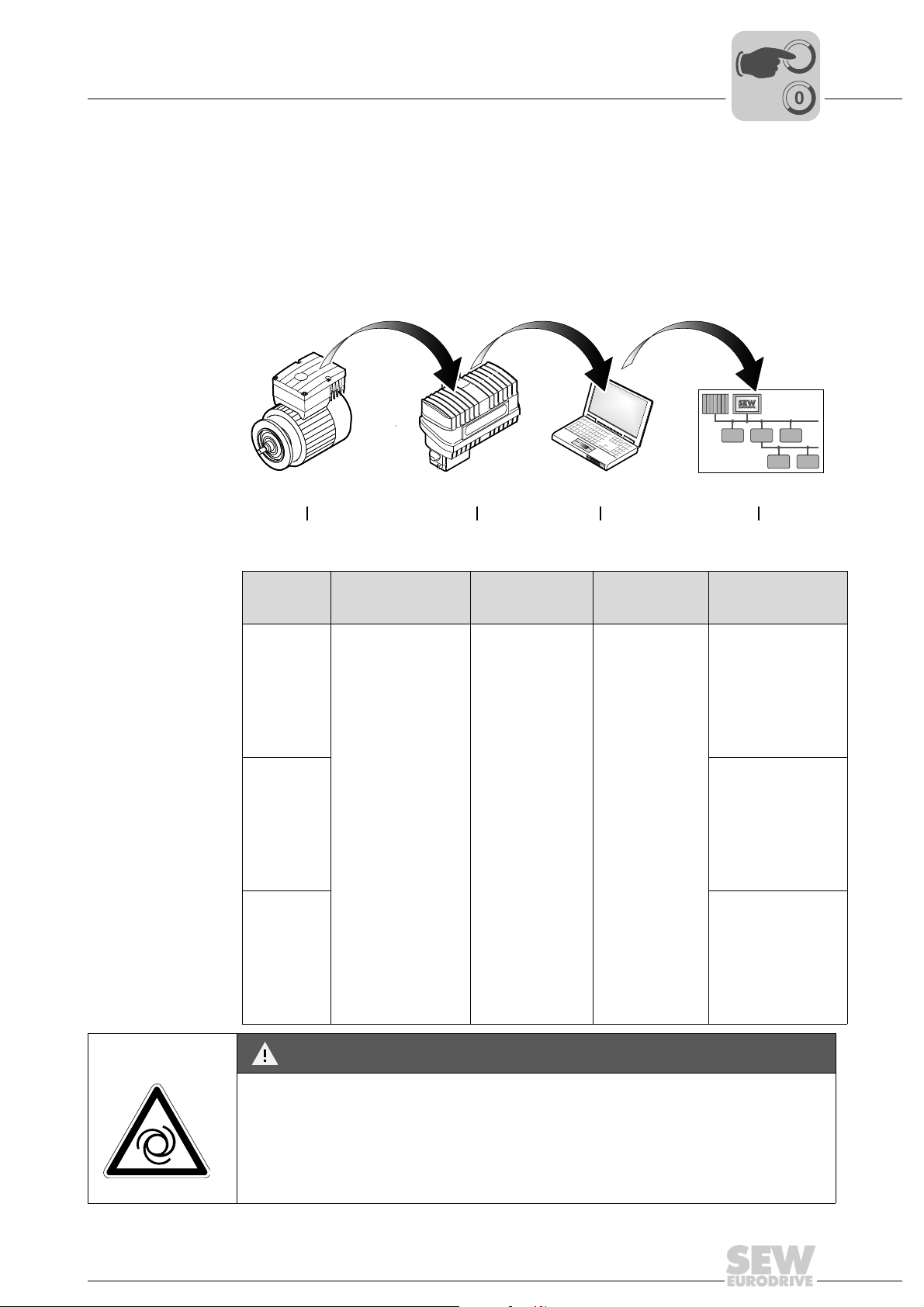
4.1 Startup procedure for MOVIFIT®-MC
The following table gives an overview of the MOVIFIT®-MC startup procedure and lists
other applicable documentation:
MOVIMOT
Function
level
Classic
PROFIBUS
Classic
PROFINET
IO
Classic
DeviceNet
®
MOVIFIT
1. 2. 4.
1.
Startup
®
-MC
®
®
oper-
MOVIMOT
• MOVIFIT
operating instructions
• MOVIMOT
ating instructions
®
-MC Parameter setting
3.
2.
Startup
®
-MC
®
-MC
MOVIFIT
MOVIFIT
operating instructions
Parameter
–•PROFIBUS-DP,
3.
setting
Fieldbus configuration
58971AEN
4.
Fieldbus
configuration
see page 11
• Process data
description, see
page 64
• Fault responses,
see page 83
• Technical data,
see page 132
• PROFINET IO,
see page 32
• Process data
description,
see page 64
• Fault responses,
see page 83
• Technical data,
see page 133
• DeviceNet,
see page 46
• Process data
description,
see page 64
• Fault responses,
see page 83
• Technical data,
see page 133
DANGER
If you are using applications with safe disconnection (only possible with MOVIFIT
or -FC), you must additionally observe the SEW publication "Safe Disconnection for
MOVIFIT
®
".
Severe or fatal injuries.
• Observe additional startup instructions and safety conditions in the SEW publication
"Safe Disconnection for MOVIFIT
Manual – MOVIFIT® Function Level "Classic"
®
-MC
®
".
9
I
4
Startup
Startup procedure for MOVIFIT®-SC and -FC
00
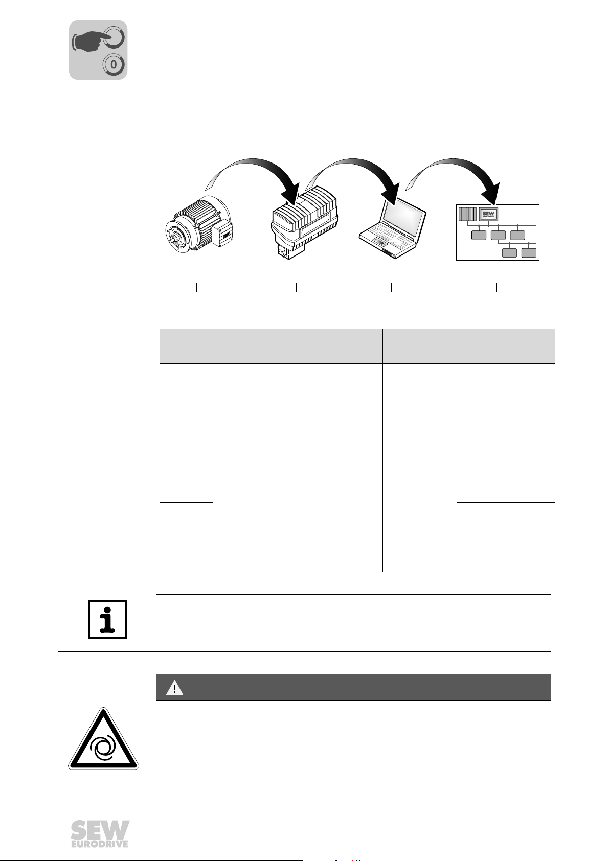
4.2 Startup procedure for MOVIFIT®-SC and -FC
The following table gives an overview of the MOVIFIT®-SC/-FC startup procedure and
lists other applicable documentation:
Motor
1. 2. 4.
Function
level
Classic
PROFIBUS
Classic
PROFINET
IO
Classic
DeviceNet
MOVIFIT®-SC/-FC Parameter setting
1.
Startup
Motor
"DR/DV/DT/DTE/DVE
AC Motors, CT/CV
Asynchronous Servomotors" operating
instructions
2.
Startup
MOVIFIT
• MOVIFIT
• MOVIFIT
®
operating
instructions
operating
instructions
-SC/-FC
®
-SC
®
-FC
3.
3.
Parameter
setting
Parameter setting and diagnostics, see page 85
Fieldbus configuration
59761AEN
4.
Fieldbus
configuration
• PROFIBUS DP,
see page 11
• Process data
description, see
page 64
• Fault responses,
see page 83
• PROFINET IO,
see page 32
• Process data
description,
see page 64
• Fault responses,
see page 83
• DeviceNet,
see page 46
• Process data
description,
see page 64
• Fault responses,
see page 83
10
NOTE
• Parameters only have to be set in the "Classic" function level when "expert mode"
is activated.
• For information about "easy mode", see the relevant MOVIFIT
®
operating instruc-
tions.
DANGER
If you are using applications with safe disconnection (only possible with MOVIFIT
or -FC), you must additionally observe the SEW publication "Safe Disconnection for
MOVIFIT
®
".
®
-MC
Severe or fatal injuries.
• Observe additional startup instructions and safety conditions in the SEW publication
"Safe Disconnection for MOVIFIT
®
".
Manual – MOVIFIT® Function Level "Classic"
Project planning for the PROFIBUS master
5 PROFIBUS
NOTE
For information about PROFIBUS connection, PROFIBUS startup (addressing, etc.) or
the description of the PROFIBUS LED displays, see the relevant MOVIFIT
instructions.
5.1 Project planning for the PROFIBUS master
There are GSD files for project planning of the DP master. These files are read in with
the project planning software of the DP master and are then available for project planning of the DP master. Refer to the relevant project planning software manuals for
details on the procedure.
• Read the information in the PDF files about the GSD file.
• Install the GSD file "SEW_600A.GSD" according to the instructions of the project
planning software for the DP master.
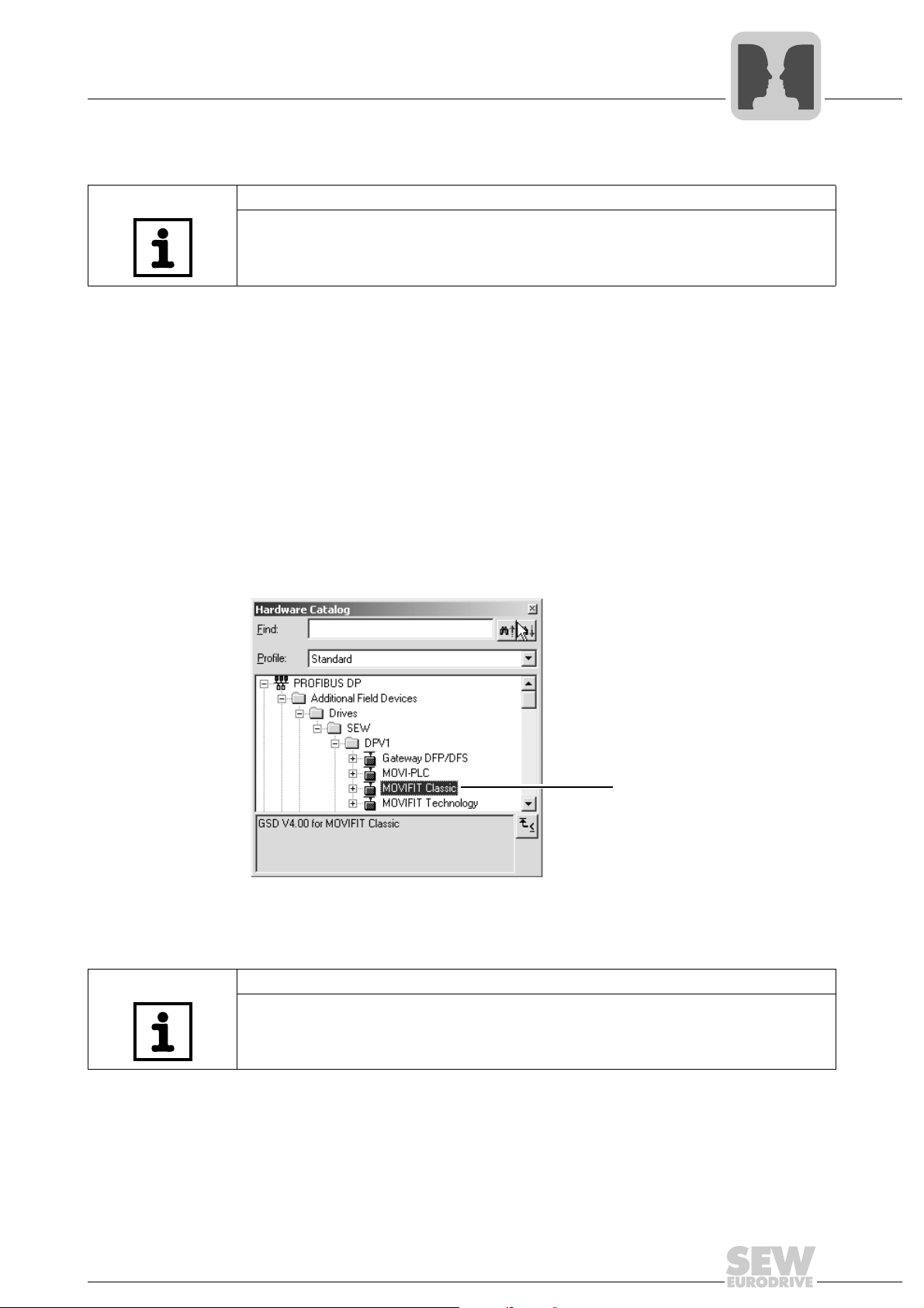
• After successful installation, the "MOVIFIT
slave stations.
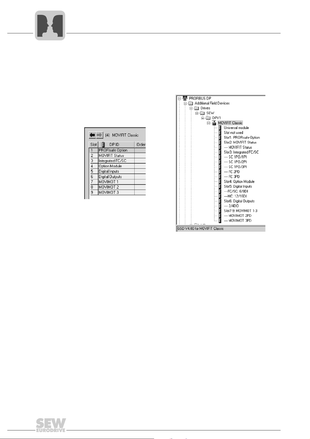
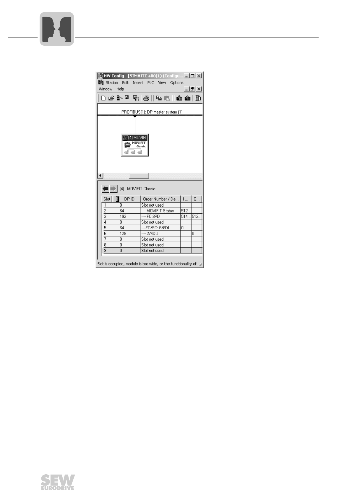
The following screenshot shows how the MOVIFIT
STEP7 HW Config:
PROFIBUS
®
operating
®
-Classic" unit is displayed in the list of
®
-Classic GSD is displayed in the
5
[1]
59741AXX
[1] MOVIFIT®-Classic GSD in STEP7 HW Config
NOTE
The latest version of the GSD files is always available on the Internet at the following
address: http://www.sew-eurodrive.com
Manual – MOVIFIT® Function Level "Classic"
11
5
PROFIBUS
Project planning for the PROFIBUS master
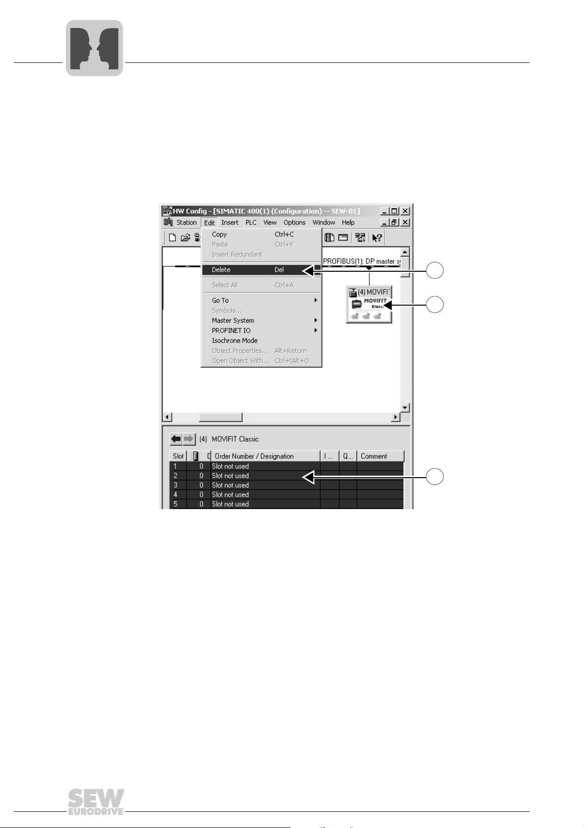
1. Add "MOVIFIT®-Classic" to the PROFIBUS structure and assign the PROFIBUS
address. This address must match the PROFIBUS address you set later in the
MOVIFIT
2. Select all MOVIFIT
3. Delete all slot entries so that you can begin project planning for your application. The
HW Config displays the assignment of the slots in plain text.
The following figure displays points 1 through 3:
®
connection box (see the appropriate MOVIFIT® operating instructions).
®
slots.
3.
1.
2.
59742AXX
12
Manual – MOVIFIT® Function Level "Classic"
PROFIBUS
Project planning for the PROFIBUS master
5
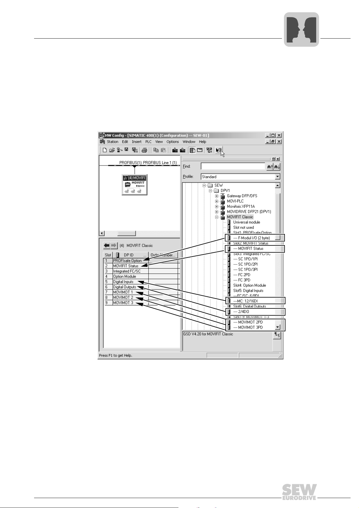
4. Select the process data configuration required for your application (see the following
examples for the various MOVIFIT
assigned to unused slots.
5. If you have performed project planning for a PROFIsafe option, you must also set the
parameters for this option. Information about this is available in the "Safe Disconnection for MOVIFIT
STEP 7 Project planning of a MOVIFIT
®
" manual.
®
versions). Note: An empty module must be
®
-MC:
Manual – MOVIFIT® Function Level "Classic"
61803AXX
13
5
PROFIBUS
Project planning for the PROFIBUS master
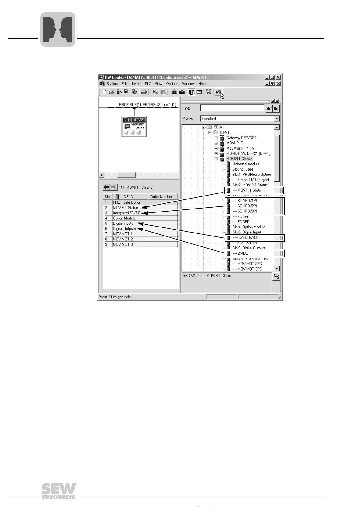
STEP 7 Project planning of a MOVIFIT®-SC:
61804AXX
14
Manual – MOVIFIT® Function Level "Classic"
Project planning for the PROFIBUS master
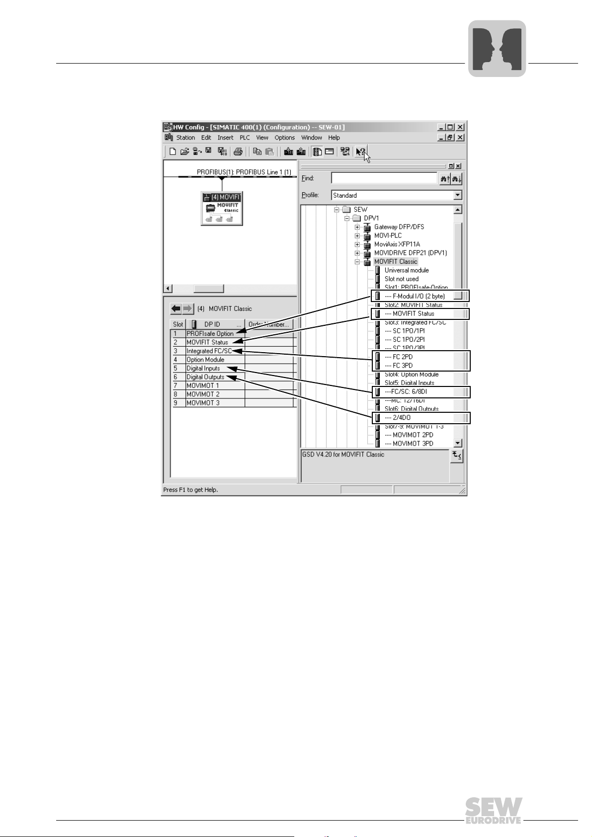
STEP 7 Project planning of a MOVIFIT®-FC:
PROFIBUS
5
61806AXX
6. Enter the I/O or periphery addresses for the configured data widths.
7. Save the configuration.
8. Add data exchange with the MOVIFIT
9. Save the project and load it into the DP master. Once the DP master has been
started, the "BUS-F" LED of the MOVIFIT
check the wiring and terminating resistors of the PROFIBUS and the project planning, especially the PROFIBUS address set in the connection box (see the corresponding MOVIFIT
®
operating instructions).
®
units to your program.
®
should go out. If this is not the case,
Manual – MOVIFIT® Function Level "Classic"
15
5
PROFIBUS
Project planning for MOVIFIT®-Classic
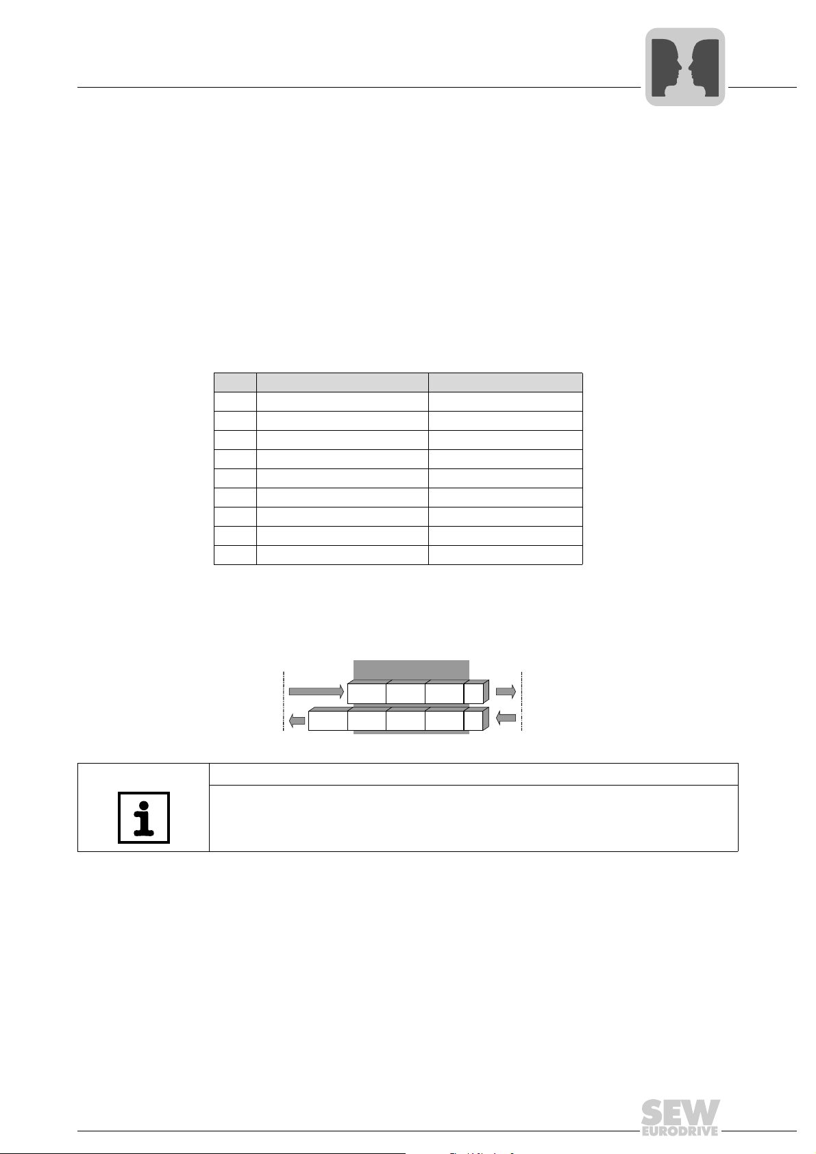
5.2 Project planning for MOVIFIT®-Classic
The slot model is used for project planning with PROFIBUS DPV1. Each slot is assigned
to a MOVIFIT
the entire MOVIFIT
The following figure demonstrates MOVIFIT
®
communication interface. The project planning process is the same for
®
-Classic line. The following division is used:
®
-Classic project planning in STEP7:
11337AXX
16
Manual – MOVIFIT® Function Level "Classic"

PROFIBUS
Project planning for MOVIFIT®-Classic
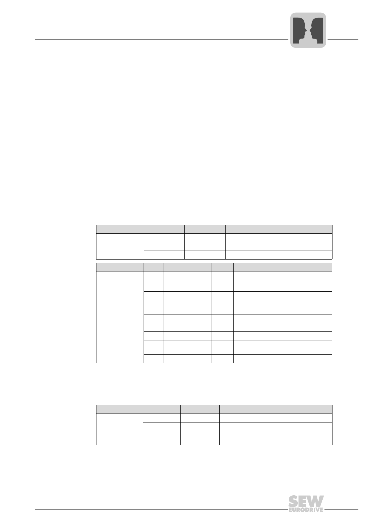
The following table shows PROFIBUS project planning for MOVIFIT®-Classic:
Slot Assignment (DP-ID) Plug-in modules Slot used in
MC FC SC
1 "PROFIsafe-Option" "Slot not used" x x
"F module I/O" (2 byte) x x
®
2"MOVIFIT
3 "Integrated FC/SC" "Slot not used" x x x
4 "Option Module" "Slot not used" x x x
5 "Digital Inputs" "Slot not used" x x x
6 "Digital Outputs" "Slot not used" x x x
7 "MOVIMOT
8 "MOVIMOT
9 "MOVIMOT
Status" "Slot not used" x x x
®
"MOVIFIT
"SC 1PO/1PI" x
"SC 1PO/2PI" x
"SC 1PO/3PI" x
"FC 2PD" x
"FC 3PD" x
"FC/SC: 6/8DI" x x
"MC: 12/16DI" x
"2/4 DO" 4DO 2DO 2DO
®
1" "Slot not used" x x x
"MOVIMOT
"MOVIMOT
®
2" "Slot not used" x x x
"MOVIMOT
"MOVIMOT
®
3" "Slot not used" x x x
"MOVIMOT
"MOVIMOT
Status" x x x
®
2PD" x
®
3PD" x
®
2PD" x
®
3PD" x
®
2PD" x
®
3PD" x
5
Submodule IDs are assigned to ensure unique identification of the unit variants. These
IDs are transferred to the Set PRM User data during startup of the PROFIBUS system.
The Prm structure ID 0x20 (32dec) is used for manufacturer-specific coding. The ID
0x05 defined according to the PROFIsafe specification is used for the F parameter
block.
Manual – MOVIFIT® Function Level "Classic"
17
5
PROFIBUS
Project planning for MOVIFIT®-Classic
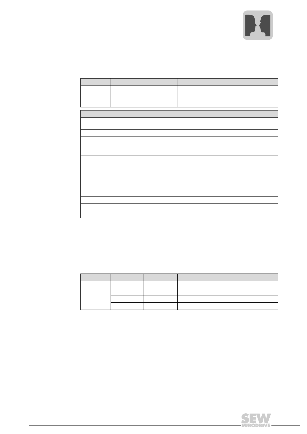
5.2.1 Application example MOVIFIT®-MC
The following application requirements should be implemented with MOVIFIT
• Three MOVIMOT
®
that the control word, the speed and the times for acceleration and deceleration
ramps are specified cyclically by the higher-level controller.
• The 12 digital inputs and 4 digital outputs of MOVIFIT
sensors and actuators.
• The sensor/actuator channels and the maintenance switches are to be monitored
within the control program.
• No options are to be used.
The following table shows the configuration example for this MOVIFIT
Slot Assignment (DP-ID) Plug-in module
1 "PROFIsafe-Option" "Slot not used"
®
2 "MOVIFIT
3 "Integrated FC/SC" "Slot not used"
4 "Option Module" "Slot not used"
5 "Digital Inputs" "MC: 12/16DI"
6 "Digital Outputs" "2/4 DO"
7 "MOVIMOT
8 "MOVIMOT
9 "MOVIMOT
Status" "MOVIFIT®-Status"
®
1" "MOVIMOT® 3PD"
®
2" "MOVIMOT® 3PD"
®
3" "MOVIMOT® 3PD"
®
-MC:
drives are controlled with 3 process data words, which means
®
are used to address external
®
-MC application.
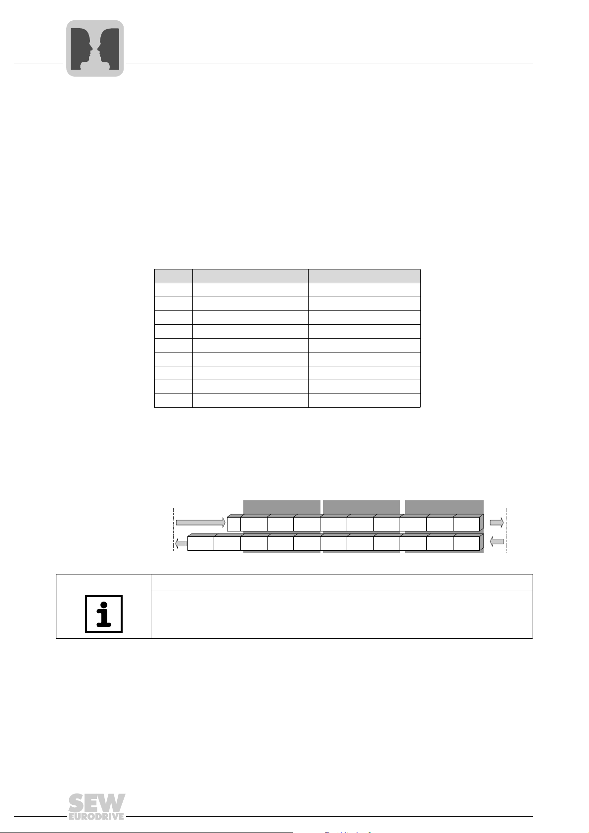
The following figure shows which process data is transferred via the bus system.
19 bytes are sent as output data from the fieldbus master to MOVIFIT
®
-MC and 22 bytes
are sent as input data to the fieldbus master.
Fieldbus
master
Status 12DI
MOVIMOT® 3MOVIMOT® 2MOVIMOT® 1
4DO
PO1 PO2 PO3 PO1 PO2 PO3 PO1 PO2 PO3
PI1 PI2 PI3 PI1 PI2 PI3 PI1 PI2 PI3
MOVIFIT
®
MC
61889AEN
NOTE
For information on the coding of process data for MOVIMOT
®
drives, digital I/Os and
status information (maintenance switches), see the "Process Data Description" section
from page 64.
18
Manual – MOVIFIT® Function Level "Classic"
PROFIBUS
Project planning for MOVIFIT®-Classic
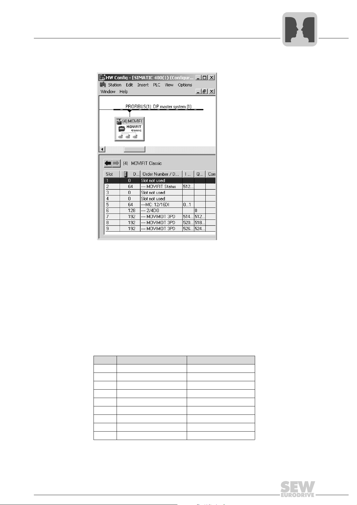
The following figure shows the MOVIFIT®-MC project planning example in STEP7:
5
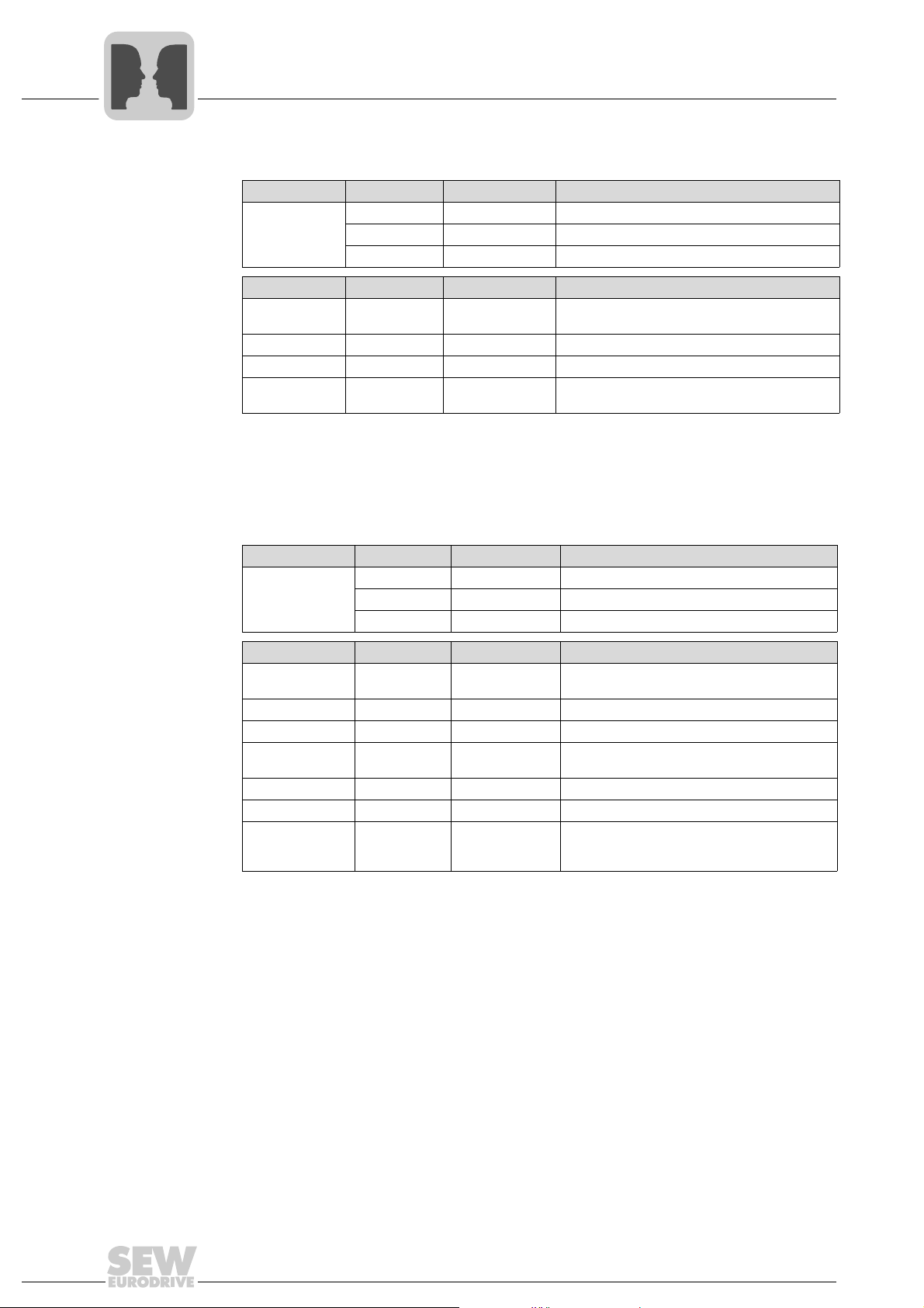
5.2.2 Application example MOVIFIT
The following application requirements should be implemented with MOVIFIT
• The integrated motor starter (SC) is to operate two motors. The current actual value
is also used for monitoring within the controller.
• Six digital inputs and two digital outputs of MOVIFIT
sensors and actuators around MOVIFIT
• The sensor/actuator channels and the maintenance switches are to be monitored
within the control program.
• No options are to be used.
The following table shows the configuration example for this MOVIFIT
Slot Assignment (DP-ID) Plug-in module
1 "PROFIsafe-Option" "Slot not used"
2 "MOVIFIT
3 "Integrated FC/SC" "SC 1PO/3PI"
4 "Option Module" "Slot not used"
5 "Digital Inputs" "FC/SC: 6/8DI"
6 "Digital Outputs" "2/4 DO"
7 "MOVIMOT
8 "MOVIMOT
9 "MOVIMOT
11338AXX
®
-SC
®
.
®
Status" "MOVIFIT® Status"
®
1" "Slot not used"
®
2" "Slot not used"
®
3" "Slot not used"
®
-SC:
®
-SC are used for external
®
-SC application:
Manual – MOVIFIT® Function Level "Classic"
19
5
PROFIBUS
Project planning for MOVIFIT®-Classic
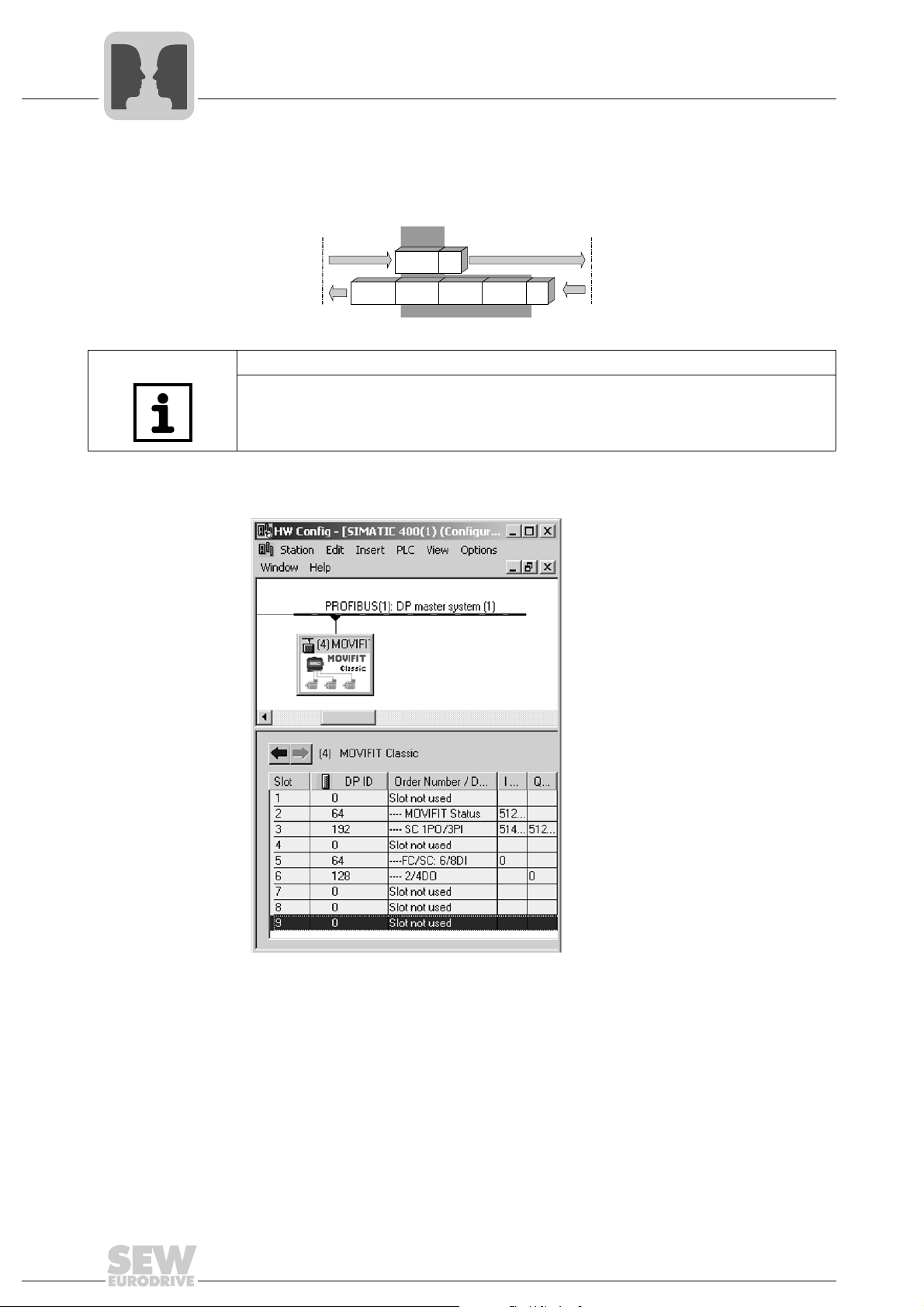
The following figure shows which process data is transferred via the bus system. 3 bytes
are sent as output data from the fieldbus master to MOVIFIT
®
-SC. 9 bytes are sent as
input data to the fieldbus master.
SC
2DO
Fieldbus
master
Status
PO1
PI1 PI2 PI3
MOVIFIT® SC
6DI
61891AEN
NOTE
For information on the coding of process data for MOVIFIT
®
-SC digital I/Os and status
information (maintenance switches), see the "Process Data Description" section from
page 64.
The following figure shows the MOVIFIT
®
-SC project planning example in STEP7:
20
11340AXX
Manual – MOVIFIT® Function Level "Classic"
PROFIBUS
Project planning for MOVIFIT®-Classic
5
5.2.3 Application example MOVIFIT®-FC
The following application requirements should be implemented with MOVIFIT
• The integrated frequency inverter (FC) is controlled with 3 process data words. In
other words, the control word, the speed and the times for acceleration and deceleration ramps are specified cyclically by the higher-level controller.
• Six digital inputs and two digital outputs of MOVIFIT
sors and actuators around MOVIFIT
• The sensor/actuator channels and the maintenance switches are to be monitored
within the control program.
• No options are to be used.
The following table shows the configuration example for this MOVIFIT
Slot Assignment (DP-ID) Plug-in module
1 "PROFIsafe-Option" "Slot not used"
®
2 "MOVIFIT
3 "Integrated FC/SC" "FC 3PD"
4 "Option Module" "Slot not used"
5 "Digital Inputs" "FC/SC: 6/8DI"
6 "Digital Outputs" "2/4 DO"
7 "MOVIMOT
8 "MOVIMOT
9 "MOVIMOT
Status" "MOVIFIT® Status"
®
1" "Slot not used"
®
2" "Slot not used"
®
3" "Slot not used"
®
-FC:
®
®
.
-FC are used for external sen-
®
-FC application:
The following figure shows which process data is transferred via the bus system. 7 bytes
are sent as output data from the fieldbus master to MOVIFIT
®
-FC and 9 bytes are sent
as input data to the fieldbus master.
FC
Fieldbus
master
Status
PO1 PO2 PO3
PI1 PI2 PI3
2DO
6DI
MOVIFIT® FC
61890AEN
NOTE
For information on the coding of process data for MOVIFIT
®
-FC digital I/Os and status
information (maintenance switches), see the "Process Data Description" section from
page 64.
Manual – MOVIFIT® Function Level "Classic"
21
5
PROFIBUS
Project planning for MOVIFIT®-Classic
The following figure shows the MOVIFIT®-FC project planning example in STEP7:
59766AXX
22
Manual – MOVIFIT® Function Level "Classic"
Parameter setting using PROFIBUS-DPV1
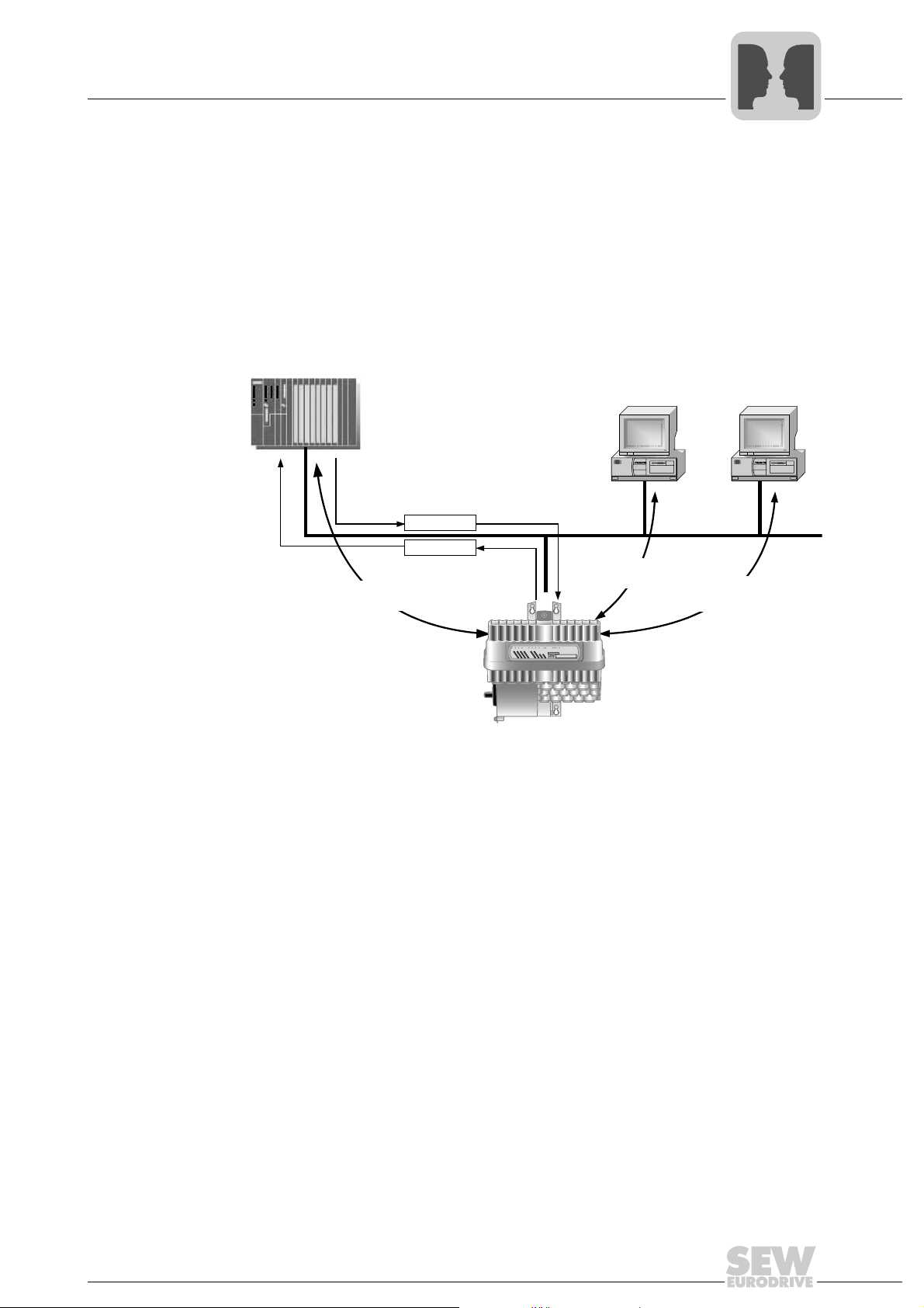
5.3 Parameter setting using PROFIBUS-DPV1
The PROFIBUS-DPV1 specification introduced new acyclical read/write services within
the context of the PROFIBUS-DP expansions. These acyclical services are added to the
current cyclical bus operation in special telegrams to ensure compatibility of
PROFIBUS-DP (version 0) and PROFIBUS-DPV1 (version 1).
The acyclical read/write services can be used for the exchange of larger volumes of data
between master and slave (drive inverter). The advantage of the acyclical data
exchange via DPV1 lies in the minimum load on the cyclical bus operation since DPV1
telegrams are only added to the bus cycle if required.
C1-Master
Cyclic OUT Data
PD
PD
Cyclic IN Data
Acyclic DP-V1
C1-Services
PROFIBUS
C2-Master
PROFIBUS DP-V1
Acyclic DP-V1
C2-Services
5
C2-Master
Acyclic DP-V1
C2-Services
D
D
D
D
D
D
D
D
I
I
I
I
I
I
I
I
0
0
0
0
0
0
0
0
1
6
5
2
4
3
0
7
/
D
O
0
0
MOVIFIT
R
2
2
S
B
R
4
4
U
Y
U
U
V
V
S
S
N
N
-
-
-
-
C
S
/
-P
F
F
D
O
S
0
1
®
59616AXX
Manual – MOVIFIT® Function Level "Classic"
23

5
PROFIBUS
Parameter setting using PROFIBUS-DPV1
5.3.1 Structure of the DPV1 parameter channel
Data sets (DS)
The user data transported via a DPV1 service is grouped in a data set. Each data set is
identified uniquely by its length, a slot number and an index. DPV1 communication with
MOVIFIT
®
uses the structure of data set 47, which is defined as a DPV1 parameter
channel for drives starting with V3.1 in the PROFIdrive profile "Drive engineering" of the
PROFIBUS user organization. Different procedures for accessing parameter data in the
drive inverter are provided via this parameter channel.
The drive parameters are usually set according to the PROFIdrive DPV1 parameter
channel of profile version 3.0 via data set index 47. The "Request ID" entry is used
to distinguish between parameter access based on PROFIdrive profile or via SEWEURODRIVE MOVILINK
possible codings of the individual elements. The data set structure is the same for
PROFIdrive and MOVILINK
®
services. The "Elements of data set DS47" section shows the
®
access.
DPV1
Read/Write
The following MOVILINK
•8-byte MOVILINK
PROFIdrive
Parameter channel DS47
®
services are supported:
®
parameter channel with all the services supported by the drive
SEW-EURODRIVE
MOVILINK
®
inverter such as
• Read parameter
• Write parameter
• Write parameter volatile
The following PROFIdrive services are supported:
• Reading (request parameter) individual parameters of type double word
• Writing (change parameter) individual parameters of type double word
24
Manual – MOVIFIT® Function Level "Classic"

PROFIBUS
Parameter setting using PROFIBUS-DPV1
5
Elements of
data set DS47
The following table shows the elements of data set DS47.
Field Data type Values
Request reference Unsigned8 0x00 reserved
0x01..0xFF
Request ID Unsigned8 0x01 Request parameter (PROFIdrive)
0x02 Change parameter (PROFIdrive)
®
0x40 SEW-EURODRIVE MOVILINK
Response ID Unsigned8 Response (+):
0x00 reserved
0x01 Request parameter (+) (PROFIdrive)
0x02 Change parameter (+) (PROFIdrive)
0x40 SEW-EURODRIVE MOVILINK
Response (-):
0x81 Request parameter (-) (PROFIdrive)
0x82 Change parameter (-) (PROFIdrive)
0xC0 SEW-EURODRIVE MOVILINK
Axis Unsigned8 0x00..0xFF Number of axis 0..255
®
0 = MOVIFIT
1 = MOVIFIT
or
1 = MOVIFIT
2 = MOVIFIT
3 = MOVIFIT
4 = MOVIFIT
No. of parameters Unsigned8 0x01..0x13 1..19 DWORDs (240 DPV1 data bytes)
Attribute Unsigned8 0x10 Value
For SEW-EURODRIVE MOVILINK
0x00 No service
0x10 Read Parameter
0x20 Write Parameter
0x30 Write Parameter volatile
0x40 Read Minimum
0x50 Read Maximum
0x60 Read Default
0x70 Read Scale
0x80 Read Attribute
0xA0..0xF0 reserved
No. of elements Unsigned8 0x00 for non-indexed parameters
0x01..0x75 Quantity 1..117
Parameter Number Unsigned16 0x0000..0xFFFF MOVILINK
Subindex Unsigned16 0x0000..0x00FF
Format Unsigned8 0x43 Double word
0x44 Fault
No. of Values Unsigned8 0x00..0xEA Quantity 0..234
Error Value Unsigned16 0x0000..0x0064 PROFIdrive-Errorcodes
0x0080 + MOVILINK
For SEW-EURODRIVE MOVILINK
fieldbus control unit
®
-FC: Integrated frequency inverter
®
-SC: Integrated motor starter
®
-MC: MOVIMOT® at terminal X71
®
-MC: MOVIMOT® at terminal X81
®
-MC: MOVIMOT® at terminal X91
®
(Request ID = 0x40):
®
parameter index
®
-AdditionalCode Low
®
16 bit error value
service
®
service (+)
®
service (-)
Manual – MOVIFIT® Function Level "Classic"
25
5
Parameter
Processing
PROFIBUS
Parameter setting using PROFIBUS-DPV1
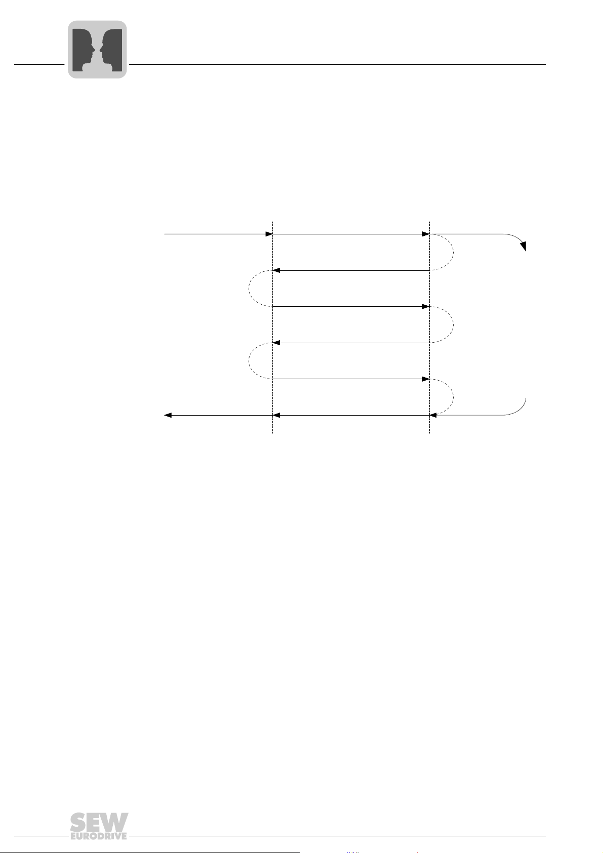
5.3.2 Procedure for setting parameters via data set 47 for PROFIBUS DPV1
Parameter access takes place with the combination of the DPV1 services "Write" and
"Read". The parameter setting service is transferred to the slave with Write.req, followed
by slave-internal processing. The master now sends a Read.req to pick up the parameter setting response. The master repeats the Read.req if the answer (Read.res) from
the slave is negative. As soon as the parameter processing in MOVIFIT
it answers with a positive response (Read.res). The user data now contains the parameter setting response of the parameter setting request that was previously sent with
Write.req (see following figure). This mechanism applies to both a C1 and a C2 master.
®
is concluded,
Parameter
Request
Parameter
Response
Write.req DS47
with data (parameter request)
Write.res
without data
Read.req DS47
without data
Read.res(-)
without data
Read.req DS47
without data
Read.res (+)
with data (parameter response)
Parameter
Request
Parameter
Processing
Parameter
Response
51658AXX
26
Manual – MOVIFIT® Function Level "Classic"
PROFIBUS
Parameter setting using PROFIBUS-DPV1
5
5.3.3 MOVILINK® parameter requests
The parameter channel of MOVIFIT
The Request ID 0x40 (SEW MOVILINK
MOVILINK
®
parameter setting requests. Parameter access with MOVILINK® services
usually takes place according to the structure described below. The typical message
sequence for data set 47 is used.
Request ID: 0x40 SEW MOVILINK
The actual service is defined by the data set element Attribute on the MOVILINK
parameter channel. The high nibble of this element corresponds to the service nibble in
the management byte of the DPV0 parameter channel.
Example for
reading a
The following tables give an example of the structure of the Write.req and Read.res user
data for reading an individual parameter via the MOVILINK
parameter via
MOVILINK
(reading a
parameter via
DPV1)
®
Sending a parameter request:
The following tables show the coding of the user data for the Write.req service including
the DPV1 header. The Write.req service is used to transfer the parameter setting
request to the drive inverter.
DPV1 header
®
is mapped directly in the structure of data set 47.
®
service) is used for the exchange of
®
-Service
®
parameter channel.
Service: Write.request Description
Slot_Number 0 Random (is not evaluated)
Index 47 Index of the data set; constant index 47
Length 10 10-byte user data for parameter request
®
Byte Field Value Description
PROFIdrive
Parameter
channel
0 Request reference 0x01 Individual reference number for the param-
1 Request ID 0x40 SEW MOVILINK
2 Axis 0x01 1: MOVIFIT
3 No. of parameters 0x01 1 parameter
4 Attribute 0x10 MOVILINK
5 No. of elements 0x00 0 = access to direct value, no subelement
6 to 7 Parameter Number 0x2267 Parameter index 8807 = P130 Ramp t11
8 to 9 Subindex 0x0000 Subindex 0
eter setting request is reflected in the
parameter response
®
service
®
inverter
UP
-FC: Integrated frequency
®
service "Read parameter"
Query parameter response:
The following table shows the coding of the Read.req user data including the DPV1
header.
Service: Read.request Description
Slot_Number 0 Random (is not evaluated)
DPV1 header
Index 47 Index of the data set; constant index 47
Length 240 Maximum length of response buffer in the DPV1
master
Manual – MOVIFIT® Function Level "Classic"
27

5
PROFIBUS
Parameter setting using PROFIBUS-DPV1
Positive MOVILINK® parameter response
The following tables show the Read.res user data with the positive response data of the
parameter setting request. The parameter value for index 8300 (firmware version) is
returned as an example.
Service: Read.request Description
Slot_Number 0 Random (is not evaluated)
DPV1 header
Byte Field Va lue Description
0 Response
1 Response ID 0x40 Positive MOVILINK
2 Axis 0x01 Reflected axis number
3 No. of
4 Format 0x43 Parameter format: Double word
5 No. of values 0x01 1 value
6 to 7 Value Hi 0x0000 Higher-order part of the parameter
8 to 9 Value Lo 0x0BB8 Lower-order part of the parameter
Index 47 Index of the data set: constant index 47
Length 10 10-byte user data for order buffer
reference
parameters
0x01 Reflected reference number from the parameter
0x01 1 parameter
setting order
®
response
Decoding: 0x0000 0BB8 = 3000 ms
28
Manual – MOVIFIT® Function Level "Classic"
PROFIBUS
Parameter setting using PROFIBUS-DPV1
5
Example for
writing a
MOVIFIT
®
-FC
parameter via
DPV1 with
MOVILINK
®
The following tables give an example of the structure of write and read services for
writing the value 3000 ms (BB8
) to the parameter "P130 Ramp t11 up" in the non-
hex
volatile memory (parameter index 8807, subindex 0). Note: The parameters of a
MOVIFIT
DPV1 header
Byte Field Va lue Description
0 Request
1 Request ID 0x40 SEW MOVILINK
2 Axis 0x01 1: MOVIFIT
3 No. of
4 Attribute 0x30 MOVILINK
5 No. of elements 0x00 0 = access to direct value, no subelement
6 to 7 Parameter
8 to 9 Subindex 0x0000 Subindex 0
10 Format 0x43 Double word
11 No. of values 0x01 Change 1 parameter value
12 to 13 Value HiWord 0x0000 Higher-order part of the parameter word
14 to 15 Value LoWord 0x0BB8 Lower-order part of the parameter word
®
-FC unit can only be changed in expert mode.
Service: Read.request Description
Slot_Number 0 Random (is not evaluated)
Index 47 Index of the data set: constant index 47
Length 16 16-byte user data for order buffer
reference
parameters
Number
0x01 Individual reference number for the parameter set-
0x01 1 parameter
0x2267 Parameter index 8807 = P130 Ramp t11 UP
ting request is reflected in the parameter response
®
service
®
-FC: Integrated frequency inverter
®
service "Write parameter volatile"
After sending this Write.request, the Write.response is received. If there was no status
conflict in processing the parameter channel, a positive Write.response results. Otherwise, the status fault is located in Error_code_1.
Query parameter response
The following tables show the coding of the Write.req user data including the DPV1
header.
Field Valu e Description
Function_Num Read.req
DPV1 header
Slot_Number X Slot_Number not used
Index 47 Index of data set
Length 240 Maximum length of response buffer in DP master
Manual – MOVIFIT® Function Level "Classic"
29
5
PROFIBUS
Parameter setting using PROFIBUS-DPV1
Positive response to "Write parameter volatile"
DPV1 header
Byte Field Val ue Description
0 Response
1 Response ID 0x40 Positive MOVILINK
2 Axis 0x00 Reflected axis number
3 No. of
5.3.4 Return codes for parameter setting
Negative
parameter
The following tables show the coding of a negative response of a MOVILINK
Bit 7 is entered in the Response ID if the response is negative.
response
DPV1 header
Service Read.response Description
Slot_Number 0 Random (is not evaluated)
Index 47 Index of the data set; constant index 47
Length 4 12-byte user data in response buffer
reference
parameters
Service: Read.response Description
Slot_Number 0 Random (is not evaluated)
Index 47 Index of the data set; constant index 47
Length 8 8-byte user data in response buffer
0x01 Reflected reference number from the parameter
0x01 1 parameter
setting order
®
response
®
service.
Byte Field Value Description
0 Response
reference
1 Response ID 0xC0 Negative MOVILINK
2 Axis 0x00 Reflected axis number
3 No. of
parameters
4 Format 0x44 Error
5 No. of values 0x01 1 error code
6 to 7 Error value 0x0811 MOVILINK
0x01 Reflected reference number from the parameter
0x01 1 parameter
setting order
®
Add.-Code 0x11 (see the table MOVILINK
return codes for DPV1)
return code, e.g. ErrorClass 0x08,
®
response
®
30
Manual – MOVIFIT® Function Level "Classic"
 Loading...