

SEW MOVIFIT FDC Operating Instructions Manual
Drive Technology \ Drive Automation \ System Integration \ Services
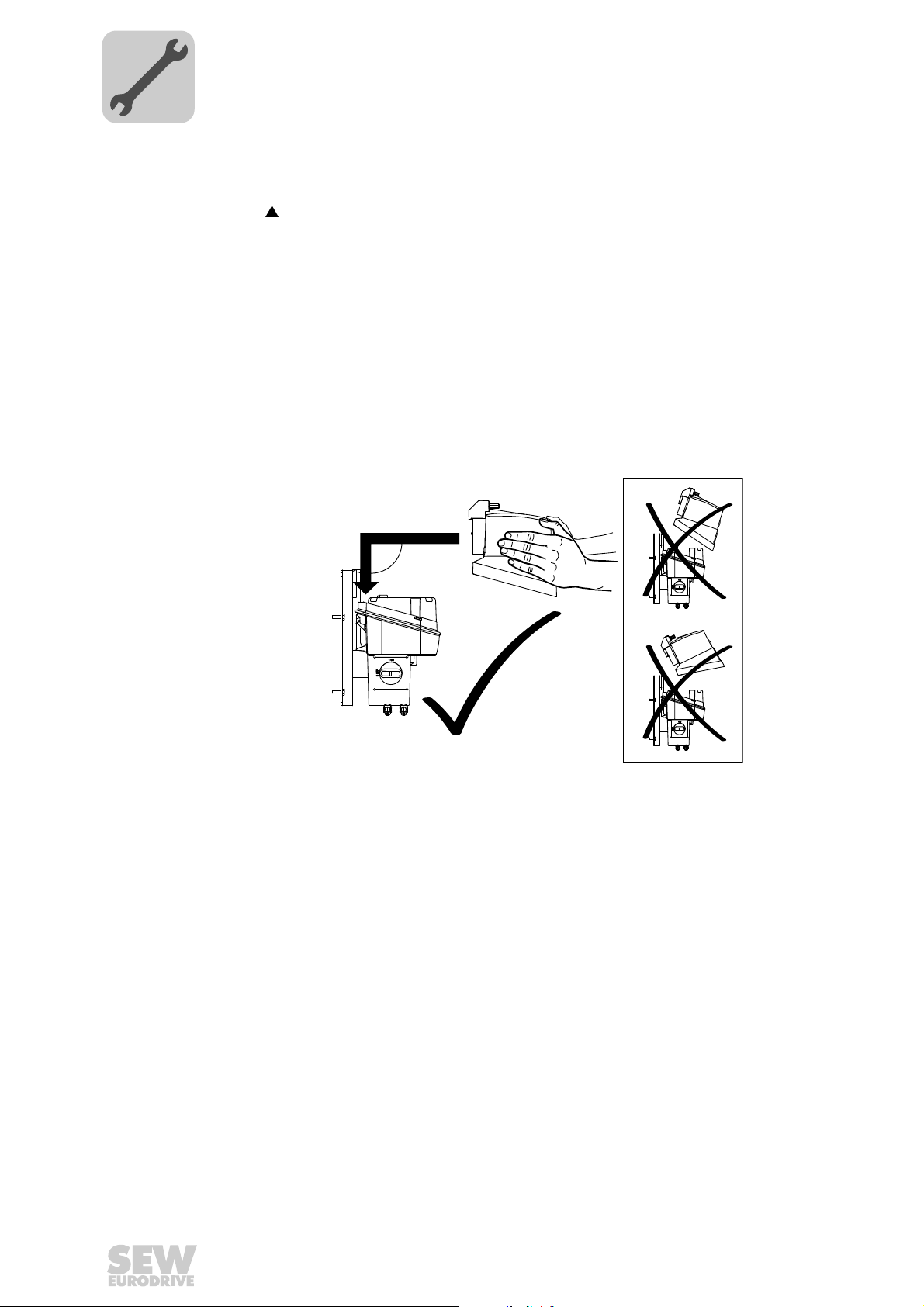
Operating Instructions
Decentralized Drive Controller
MOVIFIT
Edition 10/2012 19471211 / EN
®
FDC
SEW-EURODRIVE—Driving the world

Contents
Contents
1 General Information ............................................................................................ 5
1.1 How to use this documentation................................................................... 5
1.2 Structure of the safety notes ....................................................................... 5
1.3 Rights to claim under limited warranty ........................................................ 6
1.4 Exclusion of liability..................................................................................... 6
1.5 Copyright..................................................................................................... 6
2 Safety Notes ........................................................................................................ 7
2.1 Preliminary information ............................................................................... 7
2.2 General information .................................................................................... 7
2.3 Target group ............................................................................................... 7
2.4 Designated use ........................................................................................... 8
2.5 Other applicable documentation ................................................................. 8
2.6 Transportation and storage......................................................................... 9
2.7 Installation................................................................................................... 9
2.8 Electrical connection ................................................................................... 9
2.9 Safe disconnection...................................................................................... 9
2.10 Operation .................................................................................................. 10
3 Unit Structure .................................................................................................... 11
3.1 MOVIFIT
3.2 Overview ................................................................................................... 12
3.3 EBOX (active electronics unit) .................................................................. 13
3.4 ABOX (passive connection unit) ............................................................... 17
3.5 Version for wet areas / corrosion protection (optional) ............................. 19
3.6 Type designation MOVIFIT
4 Mechanical Installation..................................................................................... 23
4.1 General information .................................................................................. 23
4.2 Permitted mounting position ..................................................................... 23
4.3 Mounting ................................................................................................... 24
4.4 Central opening/closing mechanism ......................................................... 29
4.5 Tightening torques .................................................................................... 32
4.6 MOVIFIT
5 Electrical Installation ........................................................................................ 37
5.1 General information .................................................................................. 37
5.2 Installation planning taking EMC aspects into account............................. 37
5.3 Installation instructions (all versions) ........................................................ 40
5.4 Installation topologies ............................................................................... 46
5.5 EBOX "MTC...-R9...-00"............................................................................ 49
5.6 Standard ABOX "MTA...-S04.-...-00" ........................................................ 50
5.7 Hybrid ABOX "MTA...-S54.-...-00" ............................................................ 62
5.8 Hybrid-ABOX "MTA...-S64.-...-00" ............................................................ 64
5.9 Electrical connections ............................................................................... 66
5.10 Required SNI cables ................................................................................. 82
5.11 Recommended hybrid cables ................................................................... 83
®
FDC......................................................................................... 11
®
FDC............................................................. 21
®
FDC version for wet areas....................................................... 34
Operating Instructions – MOVIFIT® FDC
3

Contents
5.12 Connection examples ............................................................................... 84
5.13 Wiring check ............................................................................................. 87
6 Startup................................................................................................................ 88
6.1 General information .................................................................................. 88
6.2 Requirements............................................................................................ 89
6.3 Description of the DIP switches ................................................................ 89
6.4 Startup procedure ..................................................................................... 91
6.5 PC/laptop connection................................................................................ 92
6.6 Startup of MOVIFIT
6.7 First steps with MOVITOOLS
7 Operation ........................................................................................................... 95
7.1 Status LEDs of MOVIFIT
8 Service ............................................................................................................. 100
8.1 Unit diagnostics....................................................................................... 100
8.2 Unit replacement..................................................................................... 100
8.3 SEW Electronics Service ........................................................................ 102
8.4 Storage ................................................................................................... 103
8.5 Disposal .................................................................................................. 103
®
FDC ........................................................................ 92
®
MotionStudio............................................ 93
®
FDC................................................................ 95
9 Technical Data................................................................................................. 104
9.1 CE marking and UL approval.................................................................. 104
9.2 Basic unit ................................................................................................ 105
9.3 Electronics data ...................................................................................... 106
9.4 Communication and control unit ............................................................. 107
9.5 Interfaces ................................................................................................ 108
9.6 Options and accessories......................................................................... 110
9.7 Required connection cables for single-line installation ........................... 111
9.8 Specification of recommended hybrid cable ........................................... 113
9.9 Dimension drawings................................................................................ 115
10 Declaration of Conformity .............................................................................. 118
11 Address List .................................................................................................... 119
Index................................................................................................................. 131
4
Operating Instructions – MOVIFIT® FDC
General Information
How to use this documentation
1
1 General Information
MOVIFIT® FDC
1.1 How to use this documentation
This documentation is an integral part of the product and contains important information
on operation and service. The documentation is intended for all employees who perform
assembly, installation, startup and service work on the product.
The documentation must be kept accessible and legible. Ensure that persons responsible for the system and its operation, as well as persons who work independently on the
unit, have read through the entire documentation and have understood it. If you are unclear about any of the information in this documentation or require further information,
please contact SEW-EURODRIVE.
1.2 Structure of the safety notes
1.2.1 Meaning of the signal words
The following table shows the grading and meaning of the signal words for safety notes,
notes on potential risks of damage to property, and other notes.
Signal word Meaning Consequences if disregarded
DANGER Imminent danger Severe or fatal injuries
WARNING Possible dangerous situation Severe or fatal injuries
CAUTION Possible dangerous situation Minor injuries
NOTICE Possible damage to property Damage to the drive system or its envi-
INFORMATION Useful information or tip: Simpli-
fies the handling of the drive
system.
ronment
1.2.2 Structure of the section-related safety notes
Section-related safety notes do not apply to a specific action, but to several actions pertaining to one subject. The used symbols indicate either a general or a specific hazard.
This is the formal structure of a section-related safety note:
SIGNAL WORD
Type and source of danger.
Possible consequence(s) if disregarded.
• Measure(s) to prevent the danger.
1.2.3 Structure of the embedded safety notes
Embedded safety notes are directly integrated in the instructions just before the description of the dangerous action.
This is the formal structure of an embedded safety note:
• SIGNAL WORD Nature and source of hazard.
Possible consequence(s) if disregarded.
– Measure(s) to prevent the danger.
Operating Instructions – MOVIFIT® FDC
5

1
General Information
Rights to claim under limited warranty
1.3 Rights to claim under limited warranty
A requirement of fault-free operation and fulfillment of any rights to claim under limited
warranty is that you adhere to the instructions in the documentation. Read the documentation before you start working with the unit.
1.4 Exclusion of liability
You must comply with the information contained in this documentation to ensure safe
operation and to achieve the specified product characteristics and performance features. SEW-EURODRIVE assumes no liability for injury to persons or damage to equipment or property resulting from non-observance of these operating instructions. In such
cases, any liability for defects is excluded.
1.5 Copyright
© 2012 – SEW-EURODRIVE. All rights reserved.
Copyright law prohibits the unauthorized reproduction, modification, distribution, and
use of this instruction manual, in whole or in part.
6
Operating Instructions – MOVIFIT® FDC

2 Safety Notes
The following basic safety notes must be read carefully to prevent injury to persons and
damage to property. The operator must ensure that the basic safety notes are read and
adhered to. Ensure that persons responsible for the system and its operation, as well as
persons who work independently on the unit, have read through the operating instructions carefully and understood them. If you are unclear about any of the information in
this documentation, or if you require further information, please contact SEWEURODRIVE.
2.1 Preliminary information
The following safety notes are primarily concerned with the use of MOVIFIT® FDC units.
If you use other SEW components, also refer to the safety notes for the respective
components in the corresponding documentation.
Please also observe the supplementary safety notes in the individual sections of this
documentation.
Safety Notes
Preliminary information
2
2.2 General information
Never install damaged products or take them into operation. Submit a complaint to the
shipping company immediately in the event of damage.
During operation, MOVIFIT
can have live, bare and movable or rotating parts as well as hot surfaces, depending on
their degree of protection.
Removing covers without authorization, improper use or incorrect installation and operation may result in severe injuries to persons or damage to machinery.
Refer to the documentation for additional information.
2.3 Target group
Only qualified electricians are authorized to install, startup or service the units or
correct unit faults (observing IEC 60364 or CENELEC HD 384 or DIN VDE 0100 and
IEC 60664 or DIN VDE 0110 as well as national accident prevention guidelines).
Qualified personnel in the context of these basic safety notes are persons familiar with
installation, assembly, startup and operation of the product who possess the necessary
qualifications.
Any activities regarding transportation, storage, operation, and disposal must be carried
out by persons who have been instructed appropriately.
®
FDC and the connected MOVIGEAR® and DRC drive units
Operating Instructions – MOVIFIT® FDC
7

2
2.4 Designated use
2.4.1 Safety functions
Safety Notes
Designated use
MOVIFIT® FDC and the connected MOVIGEAR® and DRC drive units are components
intended for installation in electrical plants or machines.
In case of installation in machines, startup of MOVIFIT
DRC drive units (i.e. start of designated operation) is prohibited until it is determined that
the machine meets the requirements stipulated in the Machinery Directive 2006/42/EC.
Startup (i.e. the start of designated use) is only permitted under observance of EMC
Directive 2004/108/EC.
MOVIFIT
regulations of the Low Voltage Directive 2006/95/EC. The standards given in the declaration of conformity are used for MOVIFIT
You must observe the technical data and information on the connection requirements
as provided on the nameplate and in the documentation.
MOVIFIT
safety functions unless these functions are described and expressly permitted.
®
FDC and the connected MOVIGEAR® and DRC drive units comply with the
®
FDC.
®
FDC and the connected MOVIGEAR® and DRC drive units may not perform
®
FDC and the MOVIGEAR® and
For safety applications, ensure that the information in the following publication is
observed:
• Manual on the functional safety of the drive unit.
Use only those components in safety applications that were explicitly designed and
delivered for this purpose by SEW-EURODRIVE.
2.5 Other applicable documentation
Also observe the documentation for MOVIGEAR® and DRC drive units:
• Operating instructions of the connected MOVIGEAR
as:
"MOVIGEAR
"MOVIGEAR
"DRC.-...-SNI" operating instructions
"DRC.-...-DSC" operating instructions
• Manual of the fieldbus interface
e.g. "Communication Controller DHR21B/41B and MOVIFIT
Interface PROFINET IO" manual
• "Application Configurator" manual
®
SNI-B" operating instructions
®
DSC-B" operating instructions
®
and/or DRC drive units, such
®
FDC with Fieldbus
8
Operating Instructions – MOVIFIT® FDC

2.6 Transportation and storage
Observe the notes on transportation, storage and proper handling. Observe the climatic
conditions as stated in the "Technical Data" sections. Do not attach any additional loads.
Use suitable, sufficiently rated handling equipment (e.g. rope guides) if required.
2.7 Installation
The units must be installed and cooled according to the regulations and specifications
in the corresponding documentation.
Protect MOVIFIT
The following applications are prohibited unless explicitly permitted:
• Use in potentially explosive atmospheres.
• Use in areas exposed to harmful oils, acids, gases, vapors, dust, radiation, etc.
• Use in non-stationary applications with strong mechanical oscillation and impact
loads; see chapter "Technical Data".
®
FDC and the MOVIGEAR® and DRC drive units from improper strain.
Safety Notes
Transportation and storage
2
2.8 Electrical connection
Observe applicable national accident prevention guidelines (e.g. BGV A3) when working
on a live MOVIFIT
Perform electrical installation according to the pertinent regulations (e.g. cable cross
sections, fusing, protective conductor connection). For any additional information, refer
to the applicable documentation.
You find notes on EMC-compliant installation, such as shielding, grounding, arrangement of filters, and routing of lines in the documentation for MOVIFIT
MOVIGEAR
responsible for maintaining the limits established by EMC legislation.
Protective measures and protection devices must comply with the regulations in force
(e.g. EN 60204-1 or EN 61800-5-1).
2.9 Safe disconnection
MOVIFIT® FDC and the MOVIGEAR® and DRC drive units meet all requirements for
safe disconnection of power and electronics connections in accordance with EN 618005-1. All connected circuits must also satisfy the requirements for safe disconnection to
ensure reliable isolation.
®
FDC unit.
®
®
and DRC drive units. The manufacturer of the system or machine is
FDC and the
Operating Instructions – MOVIFIT® FDC
9

2
2.10 Operation
Safety Notes
Operation
Systems with integrated MOVIFIT® FDC and MOVIGEAR® and DRC drive units must
be equipped with additional monitoring and protection devices according to the applicable safety guidelines, such as the law governing technical equipment, accident prevention regulations, etc. Additional protective measures may be necessary for applications
with increased potential risk. It is permitted to modify MOVIFIT
MOVIGEAR
®
and DRC drive units using the operating software.
Do not touch live components or power connections immediately after disconnecting
MOVIFIT
®
FDC as well as MOVIGEAR® and DRC drive units from the supply voltage
because some capacitors may still be charged. Wait at least 5 minutes after having
switched off the supply voltage.
As soon as supply voltage is present at the MOVIFIT
®
FDC or MOVIGEAR® and DRC
drive units, the terminal boxes of the units must be closed (i.e. the MOVIFIT
well as any connectors of SNI cables or hybrid cables must be plugged in and screwed
on). The degree of protection of MOVIFIT
®
FDC specified in the technical data chapter
applies only if the EBOX is installed on the ABOX.
Never disconnect power plug connectors during operation. Doing so can lead to danger-
ous electric arcs forming, which can cause irreparable damage to the unit (fire risk,
irreparable contacts).
Important: The maintenance switch of MOVIFIT
®
disconnects only the MOVIGEAR
and DRC drive units from the power supply system. The terminals of the MOVIFIT® FDC
unit are still connected to the power supply after the maintenance switch is activated.
The unit may still be live and connected to the supply system, even if the operation LEDs
and other display elements are no longer illuminated.
The bus cycle and timeout times effective in the system must be taken into account
during project planning and when dimensioning the system.
®
FDC as well as
®
EBOX as
®
Mechanical blocking or internal safety functions of the unit can cause a motor standstill.
Removing the cause of this problem or performing a reset can result in the MOVIGEAR
and DRC drive unit re-starting on its own. If this is not permitted for the driven machine
for safety reasons, disconnect the unit from the supply system before correcting the error.
Caution: Danger of burns: The temperature of the surface of MOVIFIT
of MOVIGEAR
®
and DRC drive units can exceed 60 ˚C during operation.
®
FDC as well as
®
10
Operating Instructions – MOVIFIT® FDC
3 Unit Structure
[1]
[2]
3.1 MOVIFIT® FDC
MOVIFIT® FDC is a decentralized drive controller for controlling the following units:
• MOVIGEAR
• MOVIGEAR
• DRC-SNI drive units
• DRC-DSC drive units
• MOVIFIT
The following figure shows the standard version of a MOVIFIT
example:
®
SNI-B drive units
®
DSC-B drive units
®
FC slave units
Unit Structure
MOVIFIT® FDC
®
FDC-SNI unit as an
3
[1] EBOX (active electronics unit)
[2] ABOX (passive connection unit)
3.1.1 Features of MOVIFIT
MOVIFIT
• Up to 10 SNI actuators or 16 SBus actuators can be connected
• Single-Line Network Installation (SNI) and/or SBus communication
• Industrial Ethernet with the following protocols:
• PROFINET IO
• Modbus/TCP
• EtherNet/IP
• Service interface via:
–USB
– Ethernet
• Maintenance switch
• 12 binary inputs + 4 binary inputs/outputs
• Configurable application modules
®
FDC
®
FDC is characterized by the following features:
4285335307
• User-defined programming in accordance with IEC 61131-3
• Easy data management with SD memory card
Operating Instructions – MOVIFIT® FDC
11
3
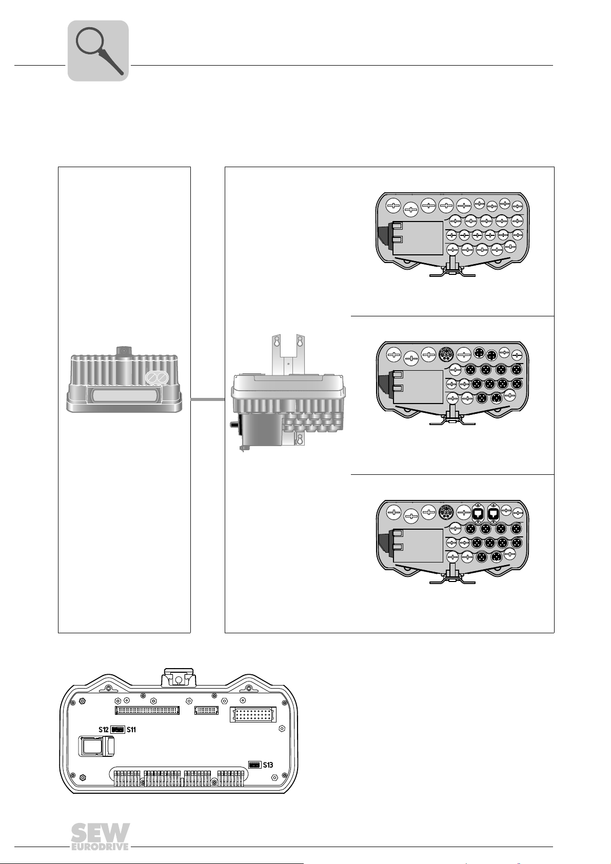
3.2 Overview
Unit Structure
Overview
The following figure shows the MOVIFIT® FDC variants described in these operating
instructions with the standard ABOX and the hybrid ABOX.
EBOX ABOX Variant
MTA...-S04.-...-0
Standard ABOX
with terminals and cable bushings
MTC...-...-00
MOVIFIT
for controlling
MOVIGEAR
®
FDC
®
and DRC drive
units
↑
X
ABOX
MTA...-S54.-...-00
Hybrid ABOX
with M23 plug connector for MOVIGEAR
DRC
and M12 for I/Os and bus
MTA...-S64.-...-00
Hybrid ABOX
with M23 plug connector for MOVIGEAR
DRC
with M12 for I/Os and push-pull RJ45 for bus
®
/
®
/
12
Detailed view of the EBOX from bottom
X:
Operating Instructions – MOVIFIT® FDC
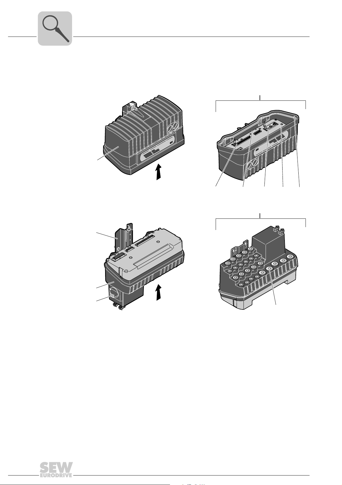
3.3 EBOX (active electronics unit)
EBOX "
MTC...-....-00"
DI03
DI01
DI02
DI00
DI04
DI05
DI06
DI07
DI08
DI09
DI10
DI11
DI12/DO00
DI13/DO01
DI14/DO02
DI15/DO03
ICE Prog
PLC
L2
A2
L1
A1
USR
NET
CAN
FDO01
FDO00
FF-STATE
RUN/MS
BF/MS
Eng-E
24V_C
MOVIFIT
®
FDC
X
S11S12
X
DI03
DI01
DI02
DI00
DI04
DI05
DI06
DI07
DI08
DI09
DI10
DI11
DI12/DO00
DI13/DO01
DI14/DO02
DI15/DO03
ICE Prog
PLC
L2
A2
L1
A1
USR
NET
CAN
FDO01
FDO00
FF-STATE
RUN/MS
BF/MS
Eng-E
24V_C
MOVIFIT
®
FDC
[1]
[4]
[9]
[3]
[2]
[7] [6]
[8]
ON
12345678
ON
12
S13
[5]
ON
12345678
Unit Structure
EBOX (active electronics unit)
3
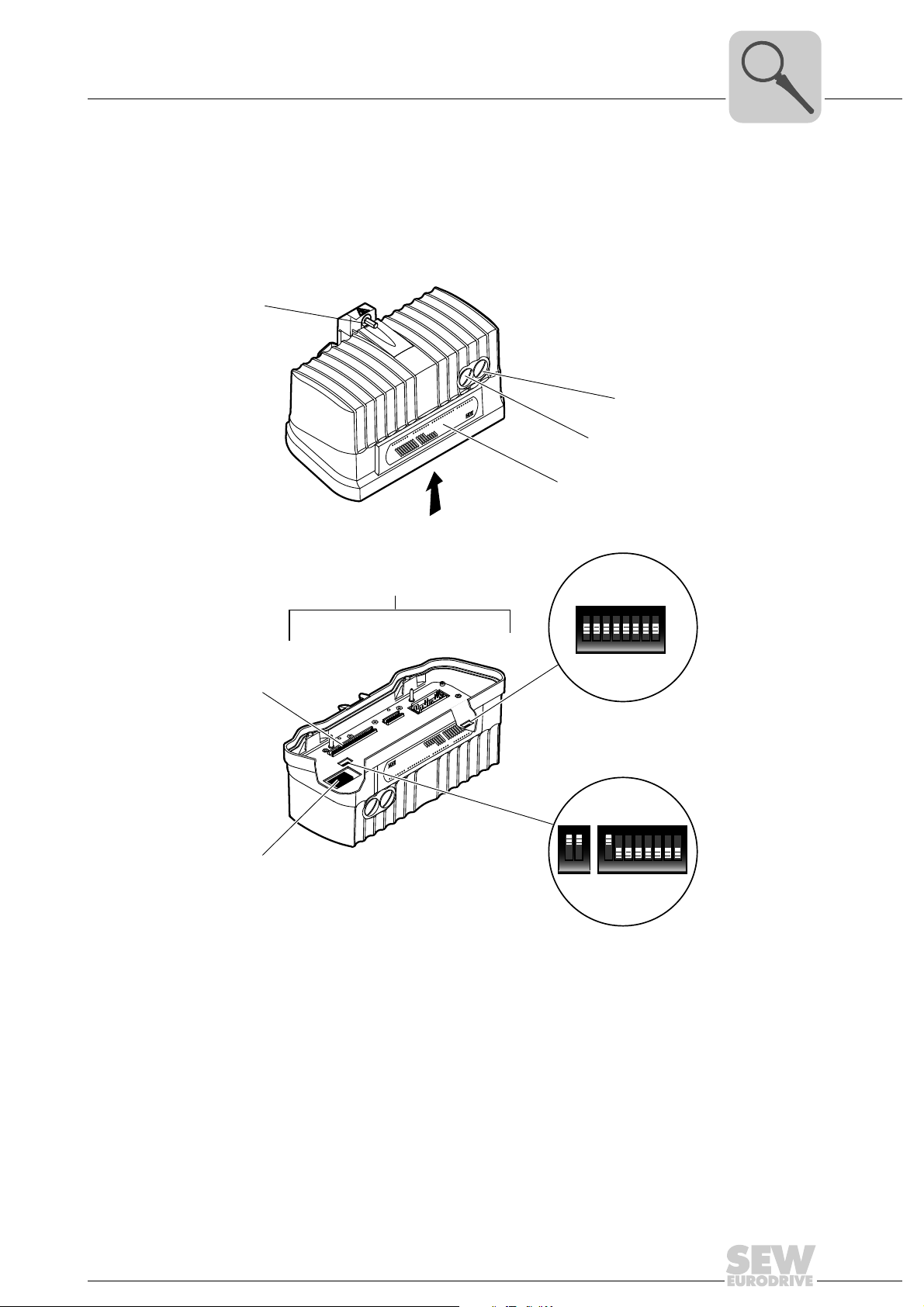
The MOVIFIT® FDC EBOX is a closed electronics unit with communication interface and
I/Os for controlling MOVIGEAR
®
and DRC drive units:
3041019531
[1] Central opening/closing mechanism
[2] EtherNet service interface (underneath the screw plug)
Use only screw plugs with part number 1 813 062 3.
[3] USB interface (underneath the screw plug)
Use only screw plugs with part number 1 813 062 3.
[4] Operation LEDs for I/Os (can be labeled), communication, and device status
[5] DIP switch S13 (reserved) Do not change the DIP switch setting.
[6] DIP switch S11 (reserved) Do not change the DIP switch setting.
[7] DIP switch S12 for selecting the communication protocol
PROFINET or EtherNet/IP
[8] SD memory card
[9] Connection to connection box
Operating Instructions – MOVIFIT® FDC
13
3
3.3.1 SD memory card
Unit Structure
EBOX (active electronics unit)
The SD memory card is used for central data management of MOVIFIT
allows for easily replacing the EBOX during servicing. It contains the firmware, the IEC
program, and user data.
You find the memory card slot inside the EBOX. This position ensures the degree of
protection of MOVIFIT
MOVIFIT
Code Performance class SD card
R95 CCU standard OMC41B-T0 Parameterizable
R96 MOVI-PLC® standard OMH41B-T0 Programmable
R97 CCU advanced OMC41B-T0
R98 MOVI-PLC
®
FDC is available with the following memory cards:
®
FDC and enables easy access.
Type Property
OMC41B-T25
®
advanced OMH41B-T0
OMH41B-T25
Parameterizable
to
Programmable
to
®
FDC and
• When using the SD memory card OMC41B-T.., you can freely set
MOVIFIT
®
FDC.
the parameters for
• When using SD memory card OMH41B-T, you can freely program
(programming languages in accordance with IEC 61131-3).
MOVIFIT® FDC
14
Operating Instructions – MOVIFIT® FDC

EBOX (active electronics unit)
3.3.2 Configurable application controller (control card)
When using an SD card of the type OMC41B-T0, you can use MOVIFIT
configurable application controller (CCU). The Application Configurator program module
can be used to execute standardized application modules created by SEWEURODRIVE. The application modules can be started up quickly and conveniently by
graphical configuration. A defined process data interface provides this functionality to
the higher-level controller. A process data monitor with control mode is available to
support the startup procedure.
Unit Structure
®
FDC as
3
Performance class
CCU standard
Performance class
CCU advanced
The performance class CCU standard is intended for application modules with singleaxis functionality and medium response times. A maximum of 16 axes (max. 10 of them
SNI axes) can be connected to a configurable application controller. The following application modules are available and can be started up using the Application Configurator
tool.
• Speed control
• Cam positioning
• Bus positioning with 6 process data
• Single-axis universal module
The performance class CCU advanced is intended for application modules with singleaxis and multi-axis functionality and fast response times. The following application
modules are available:
• Single-axis functionality:
– Speed control
– Cam positioning
– Bus positioning with 6 process data words
– Single-axis universal module
• Multi-axis functionality (in preparation):
– SyncCrane
– Energy-efficient SRU
Operating Instructions – MOVIFIT® FDC
15

3
Unit Structure
EBOX (active electronics unit)
3.3.3 Freely programmable motion and logic controller card (MOVI-PLC®)
When using an SD card of the type OMH41B-T0, you can use MOVIFIT
programmable motion and logic controller MOVI-PLC
grammable motion and logic controllers. It allows drive solutions, logic processes and
sequence controls to be automated simply and efficiently using IEC 61131-3 compliant
programming languages.
•MOVI-PLC
®
is a universal solution because it is able to control the entire portfolio
of SEW inverters and offers a simple upgrade to a more powerful MOVI-PLC
version thanks to the universal execution of the programs.
•MOVI-PLC
®
is scalable due to several different hardware platforms (standard,
advanced, etc.) and modular software concepts (libraries for numerous applications).
•MOVI-PLC
®
is powerful due to extensive technologies (such as electronic cam,
synchronous operation) and the control of demanding applications (such as material
handling).
Performance-class
MOVI-PLC
®
standard
The control card of the performance class MOVI-PLC
single axis movements and integration of external inputs/outputs as well as drive operator panels (DOP). The control card is therefore suitable for use as a module controller
or stand-alone controller for machines of medium complexity. SEW-EURODRIVE recommends the program module MultiMotion Light for programming.
®
®
. MOVI-PLC® is a series of pro-
®
standard enables coordinated
FDC as freely
®
Performance class
MOVI-PLC
®
advanced
The performance class MOVI-PLC
MOVI-PLC
technology functions, such as synchronous operation, electronic cam or robotics. SEWEURODRIVE recommends the program module MultiMotion for programming.
3.3.4 Actuator module (SNI)
The actuator module of the EBOX modulates the SNI signal onto the supply system cable. This means the same SNI cable is used for communication and power supply of the
connected MOVIGEAR
See chapter "Operation" > "Status LEDs" (page 95) for more information.
®
®
standard by short response times and the possibility of executing complex
®
and DRC drive units (SNI = Single Line Network Installation).
advanced supplements the performance class
16
Operating Instructions – MOVIFIT® FDC
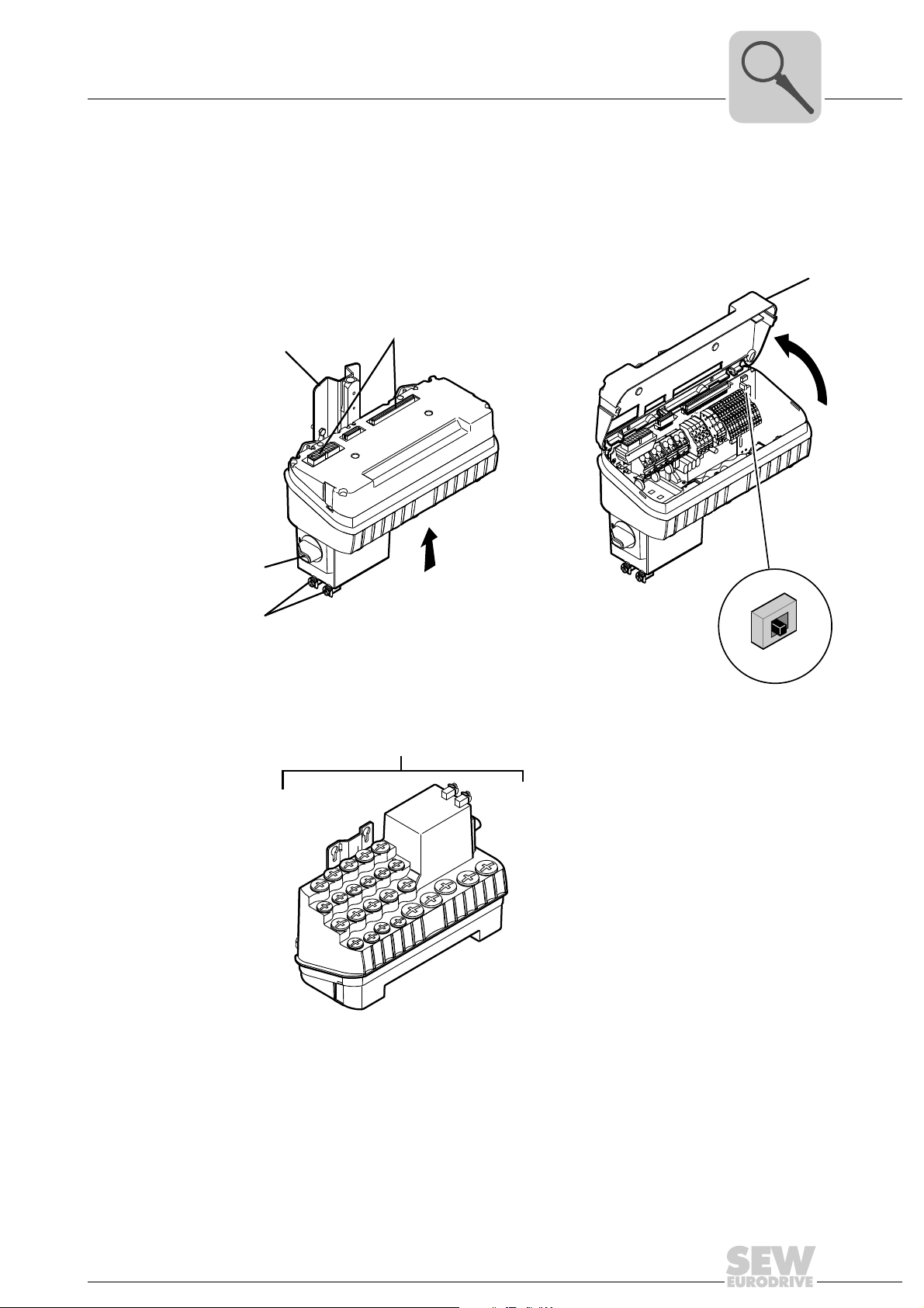
3.4 ABOX (passive connection unit)
X
ABOX "MTA...-S04.-...-00"
ABOX "MTA...-S64.-...-00"
ABOX "MTA...-S54.-...-00"
X
[1]
[6]
[5]
[3]
[2]
[4]
S3
ON
OFF
The following figure shows the MOVIFIT® standard ABOX "MTA...-S04.-...-00 as an example:
Unit Structure
ABOX (passive connection unit)
3
Operating Instructions – MOVIFIT® FDC
[1] Mounting rail
[2] Connection to EBOX
[3] Protection cover
[4] DIP switch S3 for SBus bus termination
[5] Grounding screws
[6] Maintenance switch
3041002251
17
3
3.4.1 Maintenance switch
Unit Structure
ABOX (passive connection unit)
The maintenance switch of the ABOX is used to disconnect the AC 400 V power supply
in the ABOX. The maintenance switch can be secured with 3 locks.
When the maintenance switch is in "0" position, the MOVIGEAR
are disconnected from the 400 V voltage supply. Voltage is still present on some terminals in the ABOX.
®
and DRC drive units
WARNING
Electric shock due to dangerous voltages present in the ABOX.
Severe or fatal injuries.
• Disconnect the power interface from the power supply before you perform any work
on the unit.
• Observe a minimum switch-off time of 5 minutes after disconnecting the power
supply.
INFORMATION
When a valid enable signal for a MOVIGEAR® or DRC drive unit is pending at
MOVIFIT
is set to "1".
®
FDC, the motor is supplied with current as soon as the maintenance switch
NOTICE
Increased wear of the switch contacts.
Destruction of the switch contacts.
• Do not operate the maintenance switch under load.
As an alternative, the ABOX is equipped with the following line and equipment protection:
Cable cross section
SNI cable / hybrid cable
2
4 x 2.5 mm
4 x 4.0 mm
/ 4 x AWG14 M16 15 A
2
/ 4 x AWG12 M20 20 A
Short designation Line and equipment protection
18
Operating Instructions – MOVIFIT® FDC
Unit Structure
Version for wet areas / corrosion protection (optional)
3.5 Version for wet areas / corrosion protection (optional)
3.5.1 Characteristics
The version for wet areas has the following characteristics:
• IP65 in accordance with EN 60529 (MOVIFIT
and plug connection sealed according to the relevant degree of protection)
• Easy-to-clean housing (self-draining design)
• Specially treated surface with anti-stick properties (= surface protection HP200)
• High impact resistance of the surface against mechanical damage
• Specifically treated mounting rail with anti-stick properties
(= HP200 surface treatment)
®
housing closed and all cable entries
INFORMATION
The version for wet areas is only available in connection with the standard ABOX
"MTA13...-S04.-...-00".
3
Operating Instructions – MOVIFIT® FDC
19
3
Unit Structure
Version for wet areas / corrosion protection (optional)
The following figure depicts the additional features of MOVIFIT® units in the version for
wet areas:
EBOX "
MTC13...-....-00"
DI04
DI03
DI02
DI01
DI00
[1]
ABOX "MTA13...-S04.-...-00"
[7]
X
L2
A2
L1
A1
USR
®
Eng-E
FDC
24V_C
NET
CAN
FDO01
MOVIFIT
FDO00
FF-STATE
RUN/MS
BF/MS
PLC
ICE Prog
DI15/DO03
DI14/DO02
DI13/DO01
DI12/DO00
DI11
DI10
DI09
DI08
DI07
DI06
DI05
FF-STATE
FDO00
MOVIFIT
FDO01
CAN
NET
24V_C
FDC
Eng-E
®
USR
A1
L1
A2
L2
DI00
DI01
DI02
DI03
DI04
DI05
DI06
DI07
DI08
DI09
DI10
DI11
DI12/DO00
DI13/DO01
DI14/DO02
DI15/DO03
ICE Prog
PLC
BF/MS
RUN/MS
X
[2] [4] [6]
[3]
[5]
Y
[8]
[9]
Y
[1] EBOX with special surface treatment (available only in one color)
[2] Signal plug connector
[3] Gasket between ABOX and cover plate
[4] Power plug connector
[5] Screws with thread sealant
[6] Replaceable profile seal
[7] Mounting rail with special surface treatment
[8] ABOX with special surface treatment (available only in one color)
[9] Maintenance switch
[10] Stainless steel screw plugs (optionally available)
[10]
3041025291
20
Operating Instructions – MOVIFIT® FDC
Unit Structure
[A]
[B]
[1]
[1]
Type designation MOVIFIT® FDC
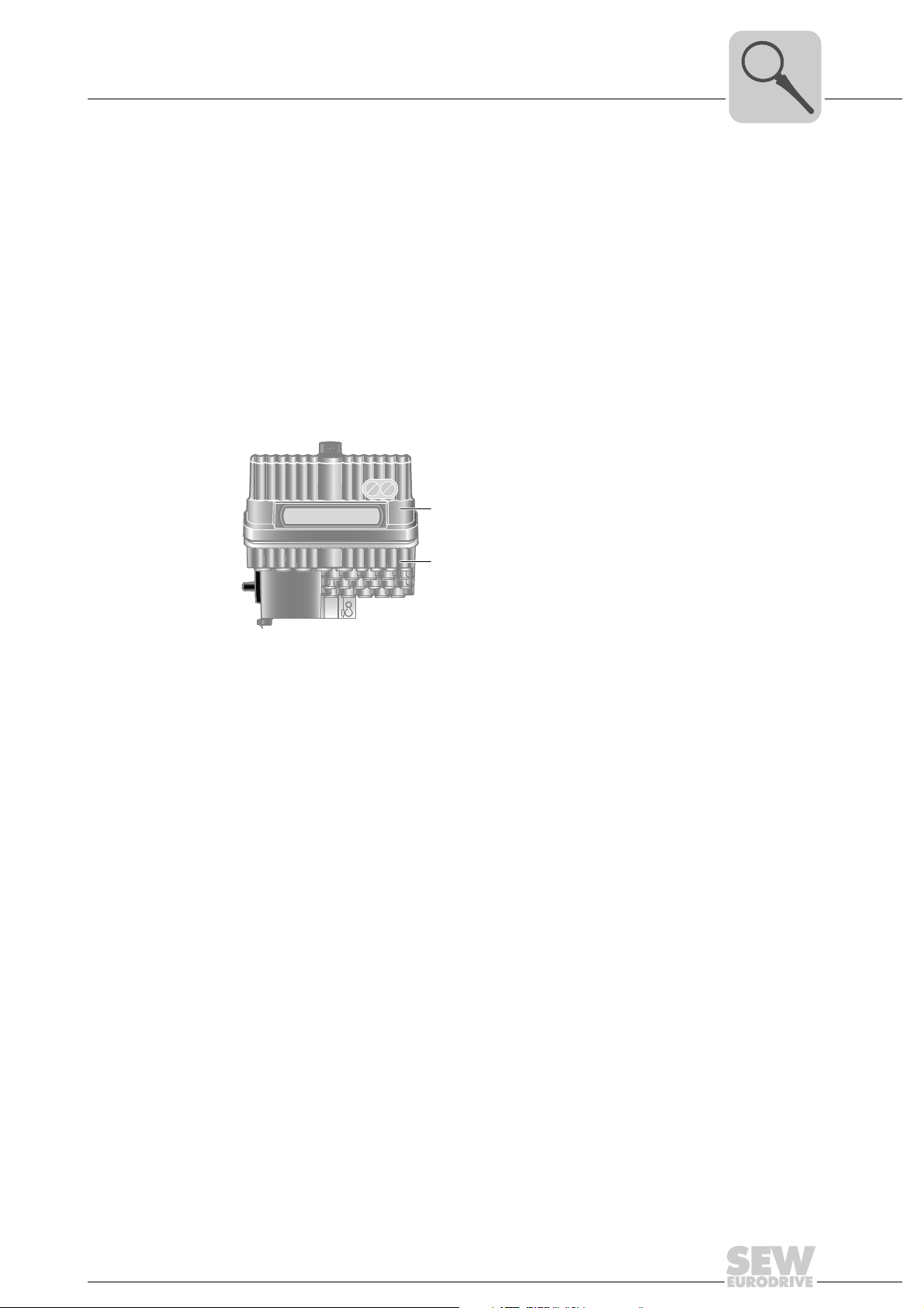
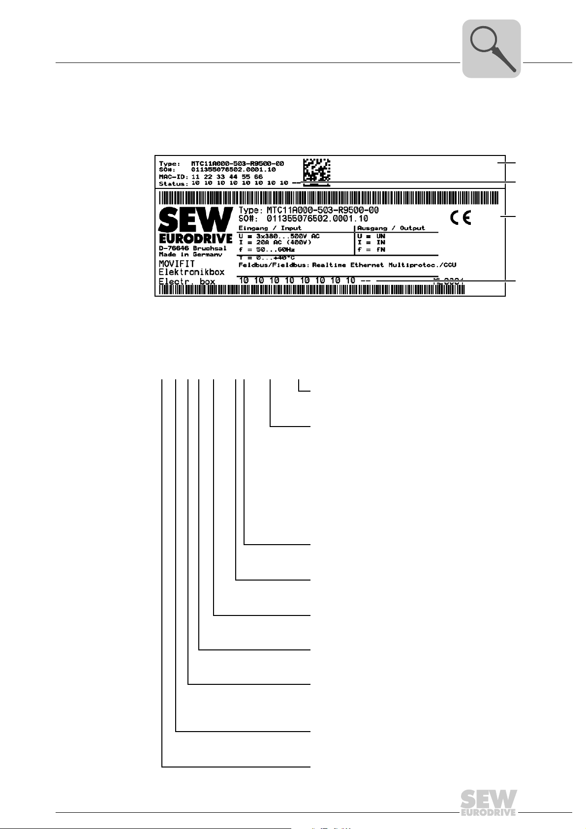
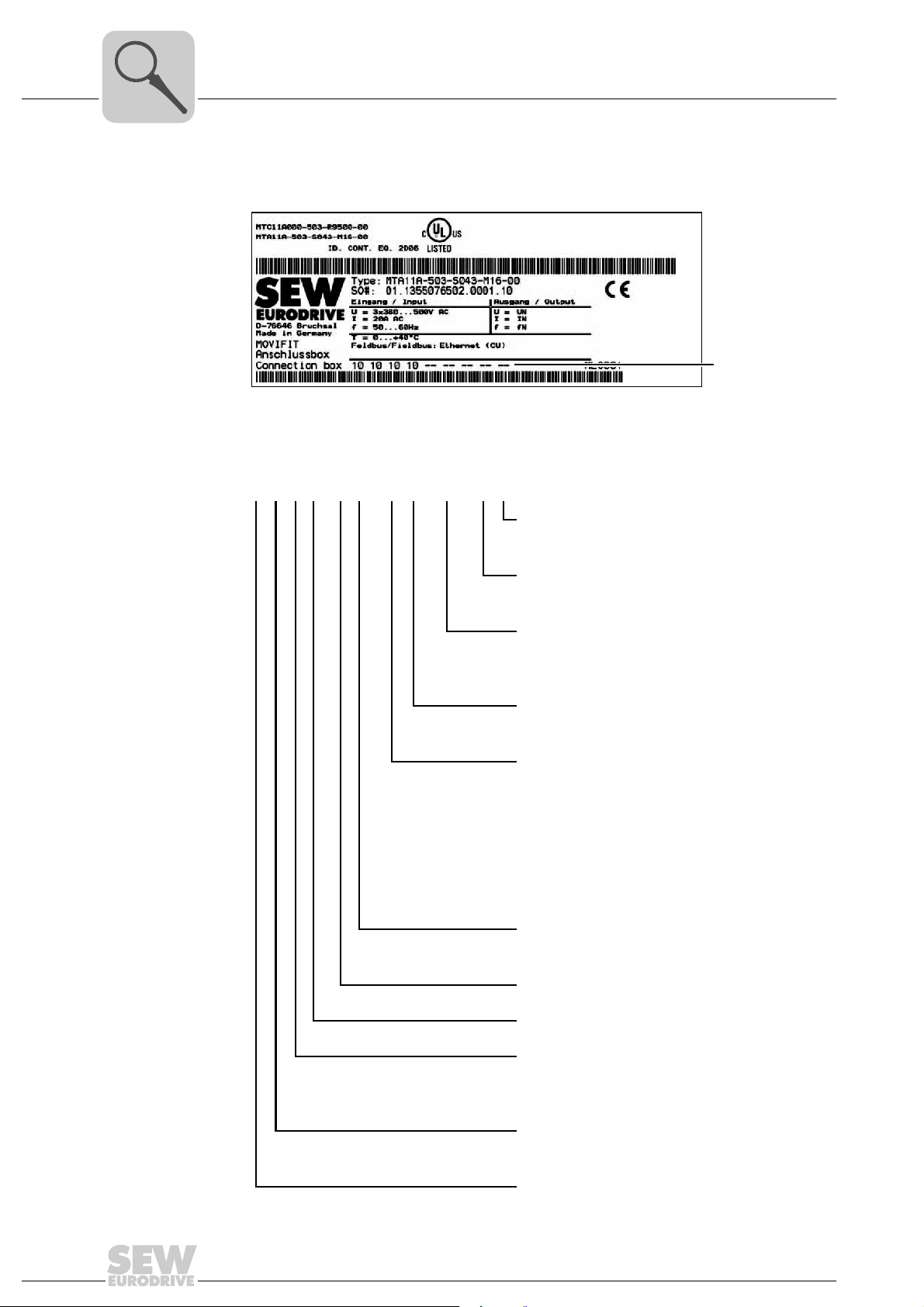
3.6 Type designation MOVIFIT® FDC
3.6.1 EBOX
Nameplate The following figure shows an example nameplate of the EBOX of MOVIFIT
®
FDC:
3
[A] External nameplate
[B]
Internal nameplate
[1]
EBOX status field
Type designation The following table shows the type designation of the EBOX of MOVIFIT
MT C 11 A 000 - 503 - R9500 - 00
EBOX variant
00 = Series
Performance class type (SD card)
R95.. = OMC41B-T0
(CCU standard, parameterizable)
R96.. = OMH41B-T0
(MOVI-PLC
R97.. = OMC41B-T0 – OMC41B-T25
(CCU advanced, parameterizable)
R98.. = OMH41B-T0 – OMH41B-T25
(MOVI-PLC
Supply phases
3 = 3-phase (AC)
Supply voltage
50 = 380 V – 500 V
®
standard, programmable)
®
advanced, programmable)
3299552907
®
FDC:
Operating Instructions – MOVIFIT® FDC
Power
000 = MTC variant (MOVIFIT
Version A
Series
11 = Standard (IP65)
13 = Variant for wet areas (IP65)
Unit type
C = MOVIFIT
MT = MOVIFIT
®
FDC
®
unit series
®
FDC)
21
3
[1]
Unit Structure
Type designation MOVIFIT® FDC
3.6.2 ABOX
Nameplate The following figure shows an example nameplate of the ABOX of MOVIFIT
[1] ABOX status field
®
FDC:
3304573579
Type designation The following table shows the type designation of the ABOX of MOVIFIT
MT A 11 A - 50 3 - S04 3 - M16 - 00 /M11
ABOX option
M11 = Stainless steel mounting rail
ABOX variant
00 = Series
Maintenance switch
M16 = Load disconnector + line protection up to 15 A
M20 = Load disconnector + line protection up to 20 A
Fieldbus
3 = PROFINET IO, EtherNet/IP, Modbus/TCP
Connection configuration
S04 = Standard ABOX
with terminals and cable bushings
S54 = Hybrid ABOX with M12 for I/Os + bus
and plug connector for MOVIGEAR
S64 = Hybrid ABOX with M12 for I/Os,
push-pull RJ45 for bus
and plug connector for MOVIGEAR
®
FDC:
®
/ DRC
®
/ DRC
22
Supply phases
3 = 3-phase (AC)
Supply voltage
50 = 380 V – 500 V
A = Version
Series
11 = Standard (IP65)
13 = Version for wet areas (IP65)
Unit type
A = ABOX (connection box)
MT = MOVIFIT
®
unit series
Operating Instructions – MOVIFIT® FDC
4 Mechanical Installation
4.1 General information
CAUTION
Risk of injury due to protruding parts, especially the mounting rail.
Risk of cutting or crushing.
• Cover sharp and protruding parts, especially the mounting rail, to protect against
injury and damage.
• MOVIFIT
Observe the following notes on mechanical installation:
• Only install MOVIFIT
structure, see "Permitted mounting position" chapter.
• Observe the general safety notes.
• Strictly observe all instructions as to the technical data and the permissible conditions regarding the place of installation.
®
FDC may only be installed by qualified personnel.
Mechanical Installation
General information
®
FDC on a level, low-vibration, and torsionally rigid support
4
• Use only the provided attachment options when mounting the unit.
• When selecting and dimensioning the mounting and safety elements, observe the
applicable standards, the technical data of the unit, and the local circumstances.
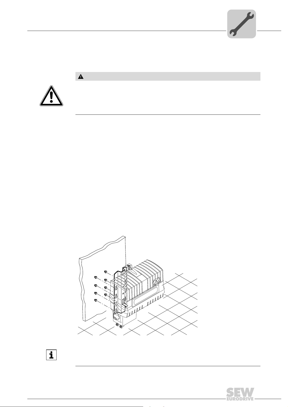
4.2 Permitted mounting position
The following figure shows the permitted mounting positions for MOVIFIT® FDC:
MOVIFIT
installed in the mounting surface. Refer to the "Mounting" chapter for more information.
®
FDC is attached by means of a mounting plate using the 4 screws already
INFORMATION
This chapter gives an example of the standard version with terminals and cable bushings. However, the installation notes apply to all variants.
Operating Instructions – MOVIFIT® FDC
3041017611
23
4
66
334.5
303.5
280
140
37,9
min. 40
15
min. 50
[1]
[2]
7.0 (6x)
13.9 (6x)
Mechanical Installation
Mounting
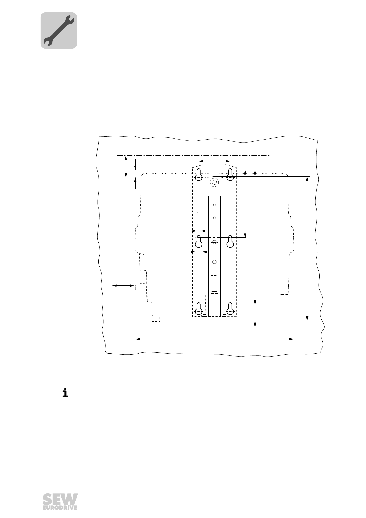
4.3 Mounting
4.3.1 Mounting rail
MOVIFIT
tion mounting surface using screws of size M6.
For bore dimensions of the respective type of fixture, see the following figures.
Drilling template for the standard mounting rail
®
FDC is equipped with a mounting rail to attach the unit to a level, low-vibra-
24
9007202299435147
INFORMATION
• [1] Observe the minimum installation clearance so that the EBOX can be removed
from the ABOX.
• [2] Observe the minimum installation clearance required to operate the maintenance switch and to ensure heat dissipation for the unit.
• Make sure that the permitted bending radii of the cables used are not exceeded
when connecting the cables.
You find detailed dimension drawings in the "Dimension drawings" (page 115) chapter.
Operating Instructions – MOVIFIT® FDC
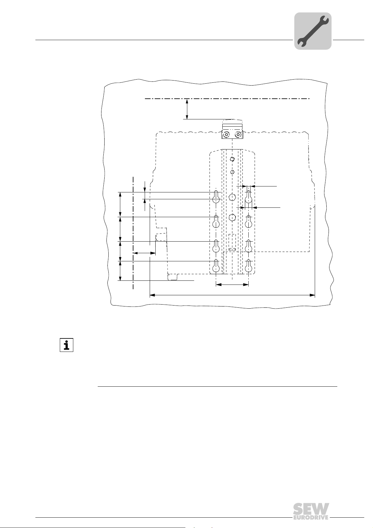
Drilling template for the optional stainless mounting rail M11
334.4
66
min. 40
min. 50
[1]
[2]
15
37.9
40 50 50
7.0 (8x)
13.9 (8x)
Mechanical Installation
Mounting
4
Operating Instructions – MOVIFIT® FDC
9007202299484811
INFORMATION
• [1] Observe the minimum installation clearance so that the EBOX can be removed
from the ABOX.
• [2] Observe the minimum installation clearance required to operate the maintenance switch and to ensure heat dissipation for the unit.
• Make sure that the permitted bending radii of the cables used are not exceeded
when connecting the cables.
You find detailed dimension drawings in the "Dimension drawings" (page 115) chapter.
25
4
min.
4 x M6
4.3.2 Mounting
Mechanical Installation
Mounting
WARNING
Risk of crushing if the load falls.
Severe or fatal injuries.
• Do not stand under the load.
• Secure the danger zone.
CAUTION
Risk of injury due to protruding parts.
Risk of cutting or crushing.
• Cover sharp and protruding parts.
• The installation must only be carried out by qualified personnel.
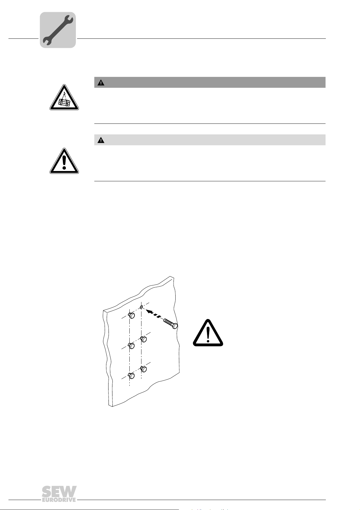
1. Bore the holes required for mounting at least 4 screws into the mounting surface according to the previous figures. SEW-EURODRIVE recommends screws of size M6
and suitable dowel pins, if necessary.
2. Mount at least 4 screws on the mounting surface.
Use appropriate washers or screw and washer assemblies for the mounting plates
with special surface treatment for versions used in wet areas.
26
758550411
Operating Instructions – MOVIFIT® FDC
Mechanical Installation
1.
2.
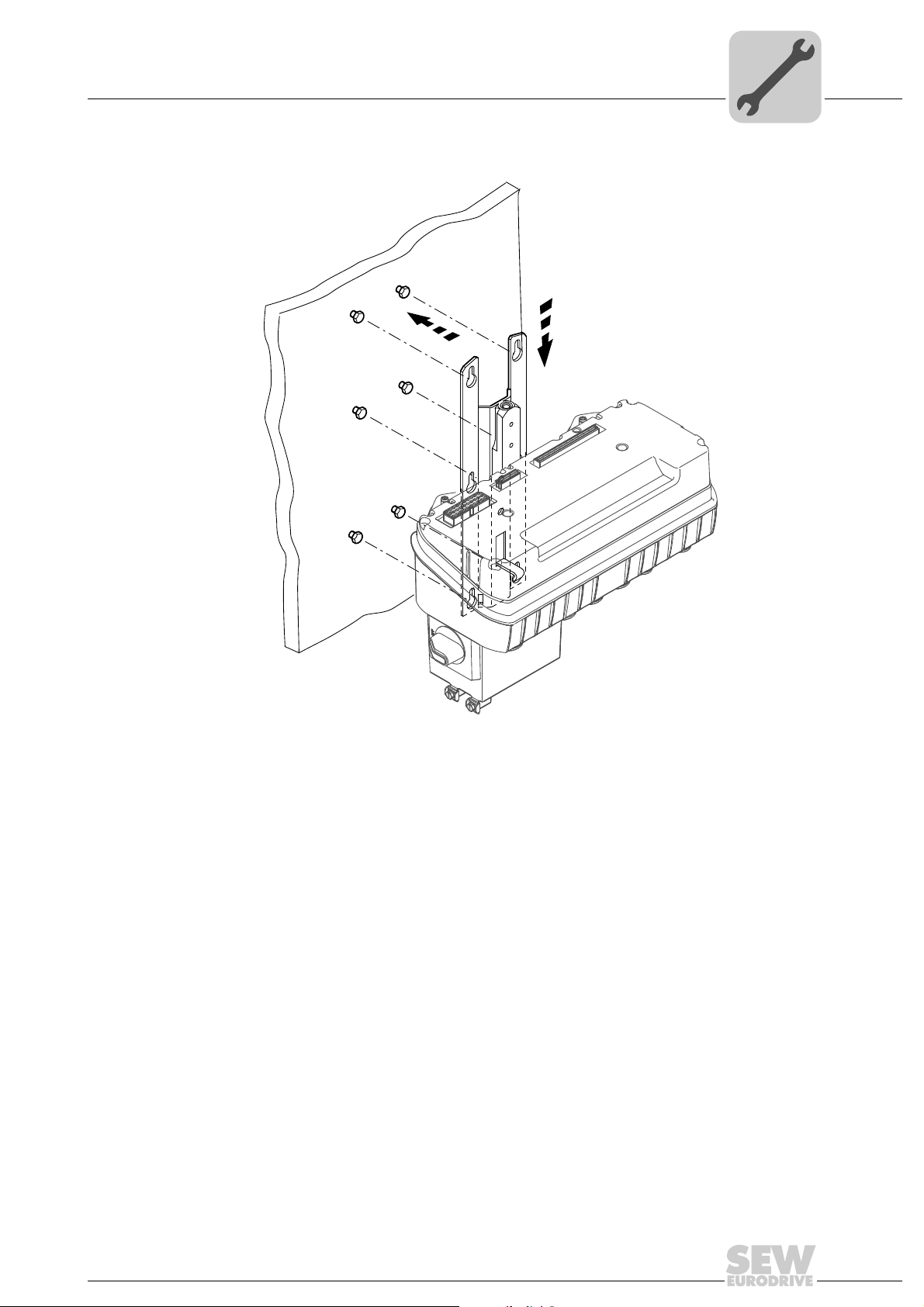
3. Hang the ABOX with the mounting rail into the screws.
Mounting
4
3045024523
Operating Instructions – MOVIFIT® FDC
27
4
Mechanical Installation
Mounting
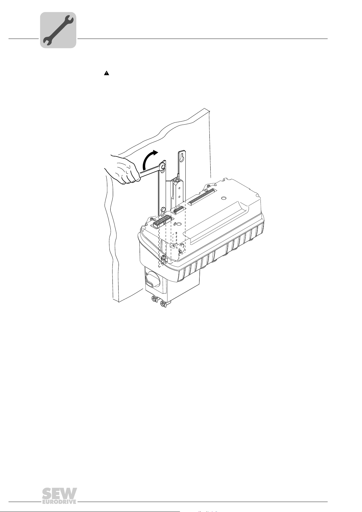
4. Tighten the screws.
CAUTION Risk of injury if the load falls.
Minor injuries
• Tighten at least 4 wall screws to ensure a secure fit after mounting.
3045189003
28
Operating Instructions – MOVIFIT® FDC
Central opening/closing mechanism
EBOX
ABOX
4.4 Central opening/closing mechanism
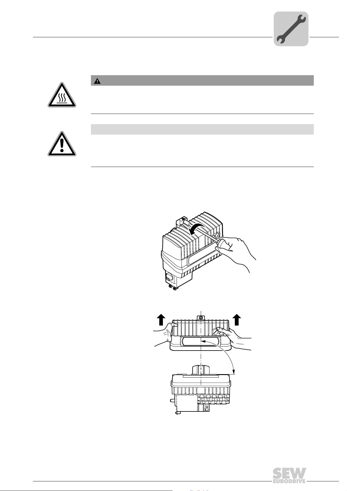
WARNING
Danger of burns due to hot surfaces of the MOVIFIT® unit.
Severe injuries.
• Do not touch the MOVIFIT
NOTICE
The enclosure specified in the technical data only applies when a unit is mounted correctly. MOVIFIT
EBOX is removed from the ABOX.
• Protect the ABOX and the EBOX when the unit is open.
4.4.1 Open
A socket wrench (SW8) is required for the central retaining screw.
®
can be damaged by moisture, dust or foreign particles when the
Mechanical Installation
®
until it has cooled down sufficiently.
4
1. Loosen the central retaining screw and continue to turn in counterclockwise direction
until the EBOX does not move further up.
3041000331
2. Remove the EBOX from the ABOX by lifting it upwards. Do not twist the EBOX.
EBOX
90°
Operating Instructions – MOVIFIT® FDC
ABOX
3041015691
29
4
4.4.2 Closing
Mechanical Installation
Central opening/closing mechanism
A socket wrench (SW8) is required for the central retaining screw.
1. NOTICE An improperly seated gasked in the EBOX creates a strong counterforce
when closing the MOVIFIT
The central opening/closing mechanism may be damaged as a result.
• Make sure that the gasked is properly seated in the groove of the EBOX.
This means that
– the gasket is inserted into the groove over the entire circumference
– and does not protrude from the groove.
2. Position the EBOX on the ABOX.
– Do not twist the EBOX in the process.
– Hold the EBOX only on the sides during the process (see following picture).
®
unit.
90°
3041013771
30
Operating Instructions – MOVIFIT® FDC
 Loading...