

Page 1
Drive Technology \ Drive Automation \ System Integration \ Services
Compact Operating Instructions
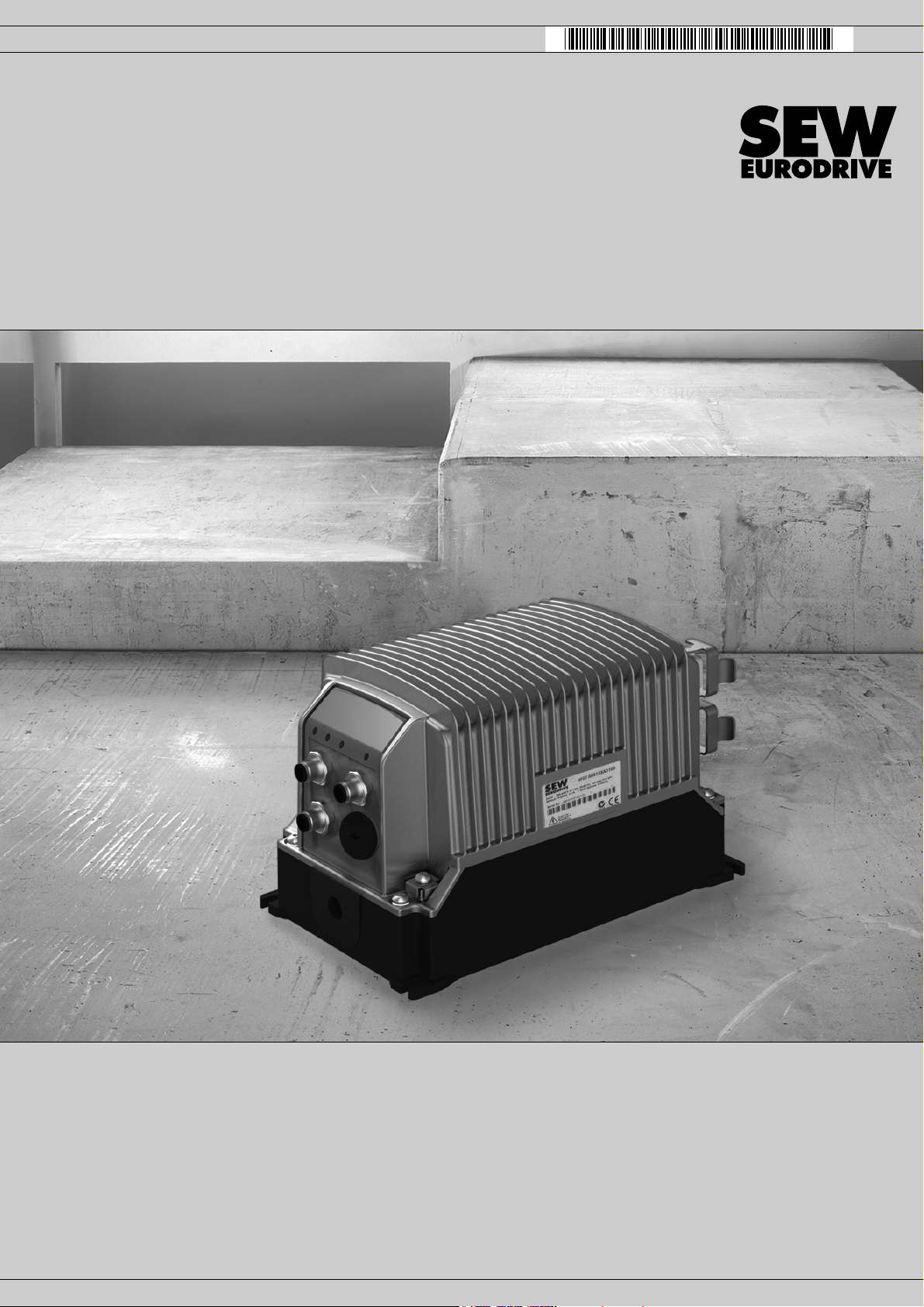
MOVIFIT
Edition 05/2011 19284810 / EN
®
basic
Page 2

SEW-EURODRIVE—Driving the world
Page 3

Contents
Contents
1 General Information ............................................................................................ 4
1.1 Scope of this documentation....................................................................... 4
1.2 Structure of the safety notes ....................................................................... 5
2 Safety Notes ........................................................................................................ 6
2.1 Preliminary information ............................................................................... 6
2.2 General information .................................................................................... 6
2.3 Target group ............................................................................................... 6
2.4 Designated use ........................................................................................... 6
2.5 Other applicable documentation ................................................................. 7
2.6 Transportation, storage............................................................................... 7
2.7 Installation................................................................................................... 7
2.8 Electrical connection ................................................................................... 7
2.9 Safe disconnection...................................................................................... 8
2.10 Operation .................................................................................................... 8
3 Type Designations .............................................................................................. 9
3.1 Nameplate................................................................................................... 9
3.2 Type designation......................................................................................... 9
4 Mechanical Installation..................................................................................... 10
4.1 Installation instructions.............................................................................. 10
4.2 Mounting position...................................................................................... 11
4.3 Installing MOVIFIT
5 Electrical Installation ........................................................................................ 12
5.1 Installation instructions.............................................................................. 12
5.2 Power bus connection (line cable) ............................................................ 15
5.3 Motor connection ...................................................................................... 20
5.4 Control unit connection ............................................................................. 22
5.5 Connections of MOVIFIT
5.6 Connections of MOVIFIT
5.7 Connection of LT-BG keypad.................................................................... 27
6 Startup................................................................................................................ 28
6.1 Important startup notes ............................................................................. 28
6.2 Startup procedure for the MOVIFIT
6.3 MOVIFIT
®
basic motor starter – startup procedure .................................. 30
6.4 Parameterization with LT-BG keypad ....................................................... 31
6.5 Functions of MOVIFIT
6.6 Functions of MOVIFIT
7 Operation ........................................................................................................... 35
7.1 Operating displays (LEDs) ........................................................................ 35
8 Service ............................................................................................................... 36
8.1 Diagnostics with LT-BG keypad ................................................................ 36
8.2 Error list of MOVIFIT
9 Declaration of Conformity ................................................................................ 39
®
basic......................................................................... 11
®
basic with AS-Interface................................... 23
®
basic with binary control ................................. 25
®
basic inverter .................................. 29
®
basic with AS-Interface ....................................... 33
®
basic with binary control ..................................... 34
®
basic...................................................................... 37
Compact Operating Instructions – MOVIFIT® basic
3
Page 4

1
General Information
Scope of this documentation
1 General Information
1.1 Scope of this documentation
This documentation comprises the general safety notes and a selected information
about MOVIFIT
• Please note that this documentation does not replace the detailed operating instructions.
• Read the detailed operating instructions before you start working with MOVIFIT
basic.
• Observe the information, instructions and notes in the detailed operating instructions
and the "AC Motors DR.71-225, 315" operating instructions. This is essential for
fault-free operation of MOVIFIT
guarantee.
• All SEW-EURODRIVE’s technical documentation and the detailed operating instructions for MOVIFIT
EURODRIVE website: www.sew-eurodrive.com.
®
basic.
®
basic and fulfillment of any rights to claim under
®
basic are available for download in PDF format from the SEW-
®
4
Compact Operating Instructions – MOVIFIT® basic
Page 5
1.2 Structure of the safety notes
1.2.1 Meaning of the signal words
The following table shows the grading and meaning of the signal words for safety notes,
notes on potential risks of damage to property, and other notes.
Signal word Meaning Consequences if disregarded
DANGER Imminent danger Severe or fatal injuries
WARNIN G Possible dangerous situation Severe or fatal injuries
CAUTION Possible dangerous situation Minor injuries
NOTICE Possible damage to property Damage to the drive system or its envi-
INFORMATION Useful information or tip: Simpli-
fies the handling of the drive
system.
1.2.2 Structure of the section-related safety notes
Section safety notes do not apply to a specific action, but to several actions pertaining
to one subject. The used symbols indicate either a general or a specific hazard.
General Information
Structure of the safety notes
ronment
1
This is the formal structure of a section safety note:
SIGNAL WORD
Type and source of danger.
Possible consequence(s) if disregarded.
• Measure(s) to prevent the danger.
1.2.3 Structure of the embedded safety notes
Embedded safety notes are directly integrated in the instructions just before the description of the dangerous action.
This is the formal structure of an embedded safety note:
• SIGNAL WORD Nature and source of hazard.
Possible consequence(s) if disregarded.
– Measure(s) to prevent the danger.
Compact Operating Instructions – MOVIFIT® basic
5
Page 6

2
Safety Notes
Preliminary information
2 Safety Notes
The following basic safety notes must be read carefully to prevent injury to persons and
damage to property. The operator must ensure that the basic safety notes are read and
adhered to. Make sure that persons responsible for the plant and its operation, as well
as persons who work independently on the unit, have read through the operating instructions carefully and understood them. If you are unclear about any of the information in
this documentation or if you require further information, please contact SEWEURODRIVE.
2.1 Preliminary information
The following safety notes are primarily concerned with the use of drives. If you use
other SEW components, also refer to the safety notes for the respective components in
the corresponding documentation.
Please also observe the supplementary safety notes in the individual sections of this
documentation.
2.2 General information
Never install or start up damaged products. Submit a complaint to the shipping company
immediately in the event of damage.
During operation, drives can have live and bare parts as well as hot surfaces, depending on their enclosure.
Removing covers without authorization, improper use as well as incorrect installation or
operation may result in severe injuries to persons or damage to property. Refer to the
documentation for additional information.
2.3 Target group
Only qualified electricians are authorized to install, startup or service the units or correct unit faults (observing IEC 60364 or CENELEC HD 384 or DIN VDE 0100 and
IEC 60664 or DIN VDE 0110 as well as national accident prevention guidelines).
Qualified personnel in the context of these basic safety notes are persons familiar with
installation, assembly, startup and operation of the product who possess the necessary
qualifications.
Any activities regarding transportation, storage, operation, and disposal must be carried
out by persons who have been instructed appropriately.
2.4 Designated use
6
drives are components intended for installation in electrical systems or machines.
In case of installation in machines, startup of units (i.e. start of designated operation) is
prohibited until it is determined that the machine meets the requirements stipulated in
the Machinery Directive 2006/42/EC.
Startup (i.e. the start of designated use) is only permitted under observance of the EMC
directive 2004/108/EC.
Compact Operating Instructions – MOVIFIT® basic
Page 7

The units meet the requirements stipulated in the Low Voltage Directive 2006/95/EC.
The standards given in the declaration of conformity apply to the units.
You must observe the technical data and information on the connection requirements
as provided on the nameplate and in the documentation.
2.4.1 Safety functions
units may not perform safety functions.
2.4.2 Hoist applications
units are not designed for hoist applications.
2.5 Other applicable documentation
Note also the following documentation:
• "DR.71-225, 315 AC Motors" operating instructions
You can download or order this publication on the Internet (http://www.sew-
eurodrive.com, under the heading "Documentation").
Safety Notes
Other applicable documentation
2
2.6 Transportation, storage
You must observe the notes on transportation, storage and proper handling. Comply
with the requirements for climatic conditions stated in chapter "Technical Data" of the
operating instructions.
2.7 Installation
The units must be installed and cooled according to the regulations and specifications
in the corresponding documentation.
Protect the units from improper strain.
The following applications are prohibited unless the unit is explicitly designed for such
use:
• Use in potentially explosive atmospheres.
• Use in areas exposed to harmful oils, acids, gases, vapors, dust, radiation, etc.
• Use in non-stationary applications with strong mechanical oscillation and impact
loads, as specified in the operating instructions.
2.8 Electrical connection
Perform electrical installation according to the pertinent regulations (e.g. cable cross
sections, fusing, protective conductor connection). For any additional information, refer
to the applicable documentation.
For notes on EMC compliant installation, such as shielding, grounding, arrangement of
filters and routing of lines, refer to chapter "Installation instructions". The manufacturer
of the system or machine is responsible for maintaining the limits established by EMC
legislation.
Compact Operating Instructions – MOVIFIT® basic
7
Page 8

2
Safety Notes
Safe disconnection
2.9 Safe disconnection
2.10 Operation
Protective measures and protection devices must comply with the regulations in force
(e.g. EN 60204 or EN 61800-5-1).
A voltage test according to EN 61800-5-1:2007 chapter 5.2.3.2 is required for the drives
prior to startup in order to ensure the insulation.
The units meet all requirements for safe disconnection of power and electronic connections in accordance with EN 61800-5-1. All connected circuits must also satisfy the
requirements for safe disconnection.
Systems with integrated units must be equipped with additional monitoring and protection devices according to the applicable safety guidelines, such as the law governing
technical equipment, accident prevention regulations, etc. Additional protective
measures may be necessary for applications with increased potential risk.
Do not touch live components or power connections immediately after disconnecting
from the supply voltage because some capacitors may still be charged. Wait at least
10 minutes after the supply voltage is switched off.
Once the supply voltages are applied to , the connection box must be closed, i.e. the
cover must be screwed on and all the plugs must be connected.
The fact that the status LEDs and other display elements are no longer illuminated does
not indicate that the unit has been disconnected from the supply system and no longer
carries any voltage.
Mechanical blocking or internal safety functions of the unit can cause a motor standstill.
Eliminating the cause of the problem or performing a reset may result in the drive restarting automatically. If, for safety reasons, this is not permitted for the driven machine,
disconnect the unit from the supply system before correcting the error.
Caution: Danger of burns: The surface temperatures of the drives can exceed 60 °C
during operation.
8
Compact Operating Instructions – MOVIFIT® basic
Page 9
3 Type Designations
3.1 Nameplate
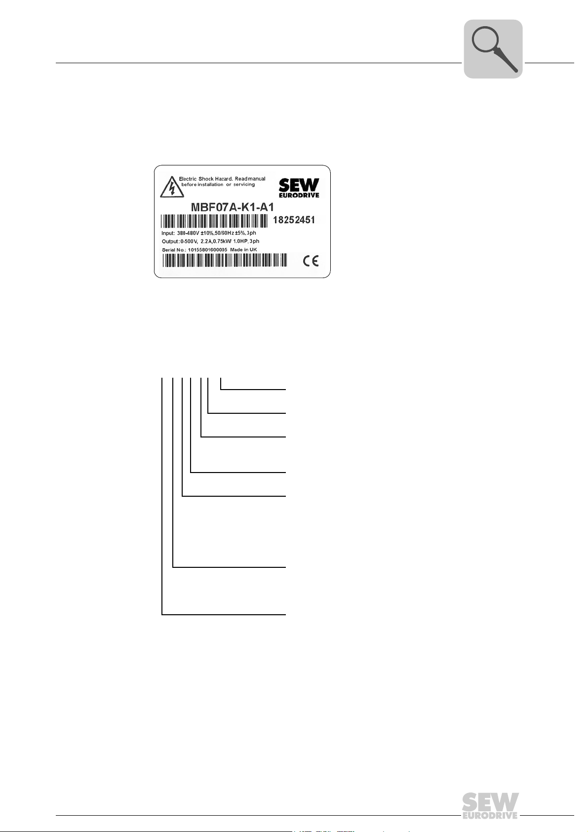
The following figure gives an example of a nameplate of the MOVIFIT® basic inverter:
Type Designations
Nameplate
3
3782535691
3.2 Type designation
The following table shows the MOVIFIT® basic type designation:
MBF07A-K1-A1
Connection module
Version
Control
K = via AS-Interface
B = binary control
Version
Motor power/variant
07 = 0.75 kW inverter
15 = 1.5 kW inverter
4R = Reversing starter
4D = Dual-motor starter (in preparation)
Design
F = Inverter
S = Motor starter
Unit series
MB = MOVIFIT
®
basic
Compact Operating Instructions – MOVIFIT® basic
9
Page 10
4
Mechanical Installation
Installation instructions
4 Mechanical Installation
4.1 Installation instructions
4.1.1 General information
NOTICE
Loss of warranted degree of protection if the MOVIFIT® basic inverter is installed
incorrectly or not at all.
Damage to the MOVIFIT
• If you remove the EBOX from the ABOX, you have to protect the EBOX and the
ABOX from moisture and dust.
Note the following when installing the MOVIFIT
• Observe the general safety notes.
• Only install the MOVIFIT
support structure.
• Ensure sufficient clearance around the unit to allow for adequate cooling. Warm
outlet air of other units must not be drawn in.
®
basic unit.
®
basic unit:
®
basic unit on a level, low-vibration, and torsionally rigid
• Strictly observe all instructions as to the technical data and the permissible conditions regarding the place of installation.
• Do only use provided attachment options when mounting the drive.
• Cover the unused plug connectors with blind caps.
The degree of protection specified in the technical data only applies for a correctly
installed MOVIFIT
4.1.2 Installation requirements
Make sure that the following requirements are met before you start installing the unit:
• The nameplate data of the MOVIFIT
• The MOVIFIT
storage).
• Ambient temperature corresponds to the specifications in chapter "Technical Data"
of the detailed operating instructions.
• The MOVIFIT
conditions:
– Potentially explosive atmospheres
– Oils
–Acids
– Gases
®
basic unit.
®
basic unit match the voltage supply system
®
basic unit is undamaged (no damage caused by transportation or
®
basic unit must not be installed under the following harmful ambient
10
– Vapors
– Radiation
–etc.
Compact Operating Instructions – MOVIFIT® basic
Page 11
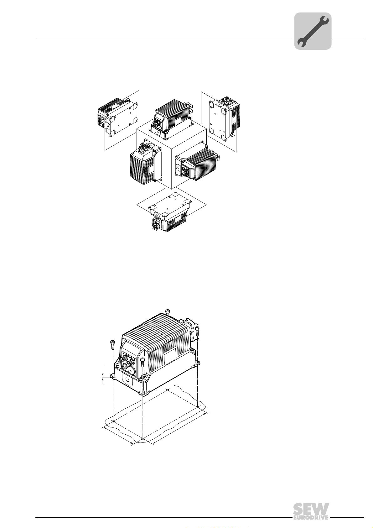
4.2 Mounting position
M1
M2
M5
M3
M4
M6
239
134
6
M5
You can install the MOVIFIT® basic unit in any mounting position.
Mechanical Installation
Mounting position
4
4.3 Installing MOVIFIT® basic
Mount the MOVIFIT® basic unit with 4 screws according to the following figure:
(Tightening torque 2.0 – 2.4 Nm (18 – 21 lb.in))
2816420235
Compact Operating Instructions – MOVIFIT® basic
9007202071159307
11
Page 12
5
Electrical Installation
Installation instructions
5 Electrical Installation
5.1 Installation instructions
5.1.1 Earth-leakage circuit breaker
Electric shock due to incorrect earth-leakage circuit breaker type.
Severe or fatal injuries.
• MOVIFIT
• Do not use a conventional earth leakage circuit-breaker as a protective device.
Universal current-sensitive earth leakage circuit-breakers (tripping current 300 mA)
are permitted as a protective device. During normal operation of MOVIFIT
units, earth-leakage currents > 3.5 mA can occur.
• SEW-EURODRIVE recommends that you do not use earth-leakage circuit breakers.
However, if an earth-leakage circuit breaker is stipulated for direct or indirect protection against contact, observe the note above in accordance with EN 61800-5-1.
WARNING
®
basic can cause direct current in the protective earth conductor. When
an earth-leakage circuit breaker is used for protection against direct or indirect
contact, only install a type B earth-leakage circuit breaker on the power supply end
of the MOVIFIT
®
basic unit.
®
basic
5.1.2 Line contactor
NOTICE
Damage due to jogging.
Damage to the MOVIFIT
• Do not use the line contactor for jogging, but only for switching the MOVIFIT
unit on and off. In jog mode, use the control signals (AS-Interface bits or binary
inputs).
• Observe a minimum switch-off time of 2 s for the line contactor.
• Only use a contactor of utilization category AC3 (EN 60947-4-1) as a line contactor.
®
basic unit.
®
basic
12
Compact Operating Instructions – MOVIFIT® basic
Page 13
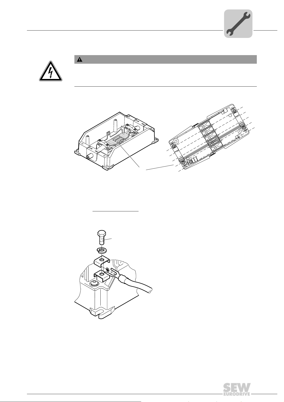
5.1.3 Notes on PE connection
M5
(2,0 – 2,5 Nm)
(18 - 21 lb.in)
WARNING
Electric shock due to incorrect connection of PE.
Severe or fatal injuries.
• Observe the following notes regarding PE connection.
Electrical Installation
Installation instructions
5
PE connection in
the unit
PE connection on
the outside of the
housing
Establish a PE connection in the unit.
BR
BU
BK
GN/YE
GY
3160365451
PE
During normal operation of the MOVIFIT
BK
unused
BK or 1
WT or GY
L1
N
L2
PE
L3
®
basic inverter, earth-leakage currents
BK or 2
GN/YE
BK or 3
WT
GN
RD
≥ 3.5 mA can occur. To meet the requirements of EN 61800-5-1, you must establish 2
PE connections.
Install a second PE conductor
with a cross section of at least the cross section of the
supply system cable:
Compact Operating Instructions – MOVIFIT® basic
2816416395
13
Page 14
5
5.1.4 EMC-compliant installation
Electrical Installation
Installation instructions
INFORMATION
This drive system is not designed for operation on a public low voltage supply system
that supplies residential areas.
This is a product with restricted availability in accordance with IEC 61800-3. It may
cause EMC interference. In this case, it is recommended for the operator to take
suitable measures.
For detailed information on EMC compliant installation, refer to the publication
"Electromagnetic Compatibility in Drive Engineering" from SEW-EURODRIVE.
With respect to the EMC regulation, frequency inverters cannot be operated as standalone units. Regarding EMC, they can only be evaluated when they are integrated in a
drive system. Conformity is declared for a described, CE-typical drive system. These
operating instructions contain further information.
5.1.5 Installation altitude above 1000 m above sea level
®
MOVIFIT
Observe the following basic conditions:
• The rated continuous power is reduced based on the reduced cooling above 1000 m
(see chapter "Technical Data" of the operating instructions).
basic drives can be also used in altitudes of 1000 – 4000 m above sea level1).
• Above 2000 m asl, the air and creeping distances are only sufficient for overvoltage
class 2. If the installation calls for overvoltage class 3, you will have to install additional external overvoltage protection to limit overvoltage peaks to 2.5 kV phase-tophase and phase-to-ground.
• If safe electrical disconnection is required, it must be implemented outside the unit
for altitudes of 2000 m above sea level and higher (safe electrical disconnection in
accordance with EN 61800-5-1).
• In installation altitudes between 2000 m to 4000 m above sea level, the permitted
nominal line voltages are reduced by 6 V per 100 m.
5.1.6 Protection devices
• MOVIFIT
load of the drive. External motor protection devices are not necessary.
5.1.7 UL compliant installation (in preparation)
UL and cUL approval for the MOVIFIT
®
basic drives are equipped with integrated protection devices against over-
®
basic unit series is in preparation.
14
1) The maximum altitude is limited by creeping distances and flameproof components, such as capacitors.
Compact Operating Instructions – MOVIFIT® basic
Page 15
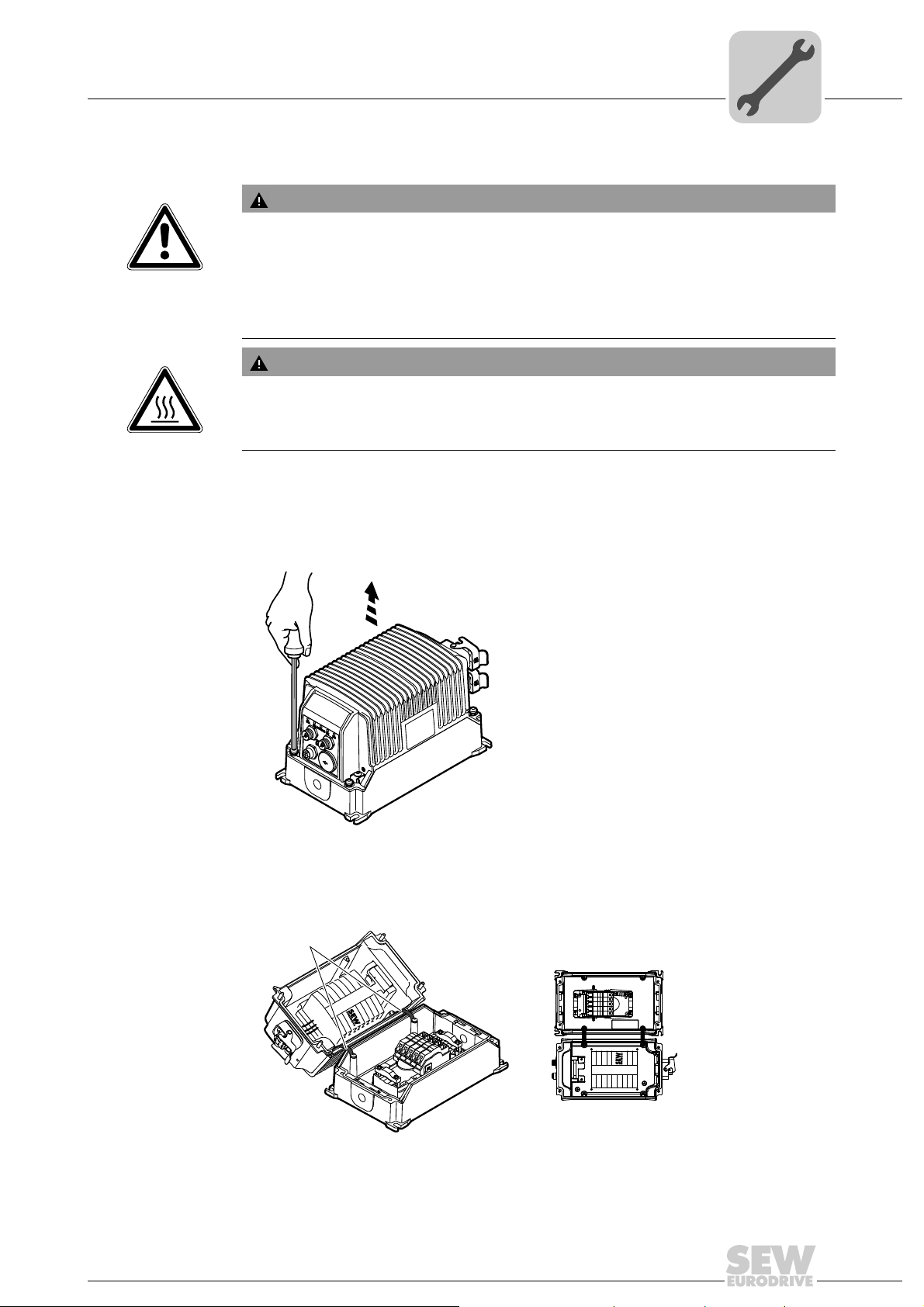
5.2 Power bus connection (line cable)
[1]
WARNING
Electric shock due to charged capacitors
Severe or fatal injuries.
• De-energize the MOVIFIT
before removing the EBOX from the ABOX.
• Secure the drive against unintended re-connection to the voltage supply.
• Then wait at least for 10 minutes.
WARNING
Danger of burns due to hot surfaces of the MOVIFIT® basic unit.
Severe injuries.
• Do not touch the MOVIFIT
Connect the MOVIFIT® basic unit to the power bus (line cable) as follows.
Electrical Installation
Power bus connection (line cable)
®
basic drive using a suitable external cut-off device
®
basic until it has cooled down sufficiently.
5
1. Loosen the 4 screws and lift up the EBOX.
2839862283
2. Loosen the EBOX straps and install them according to the mounting position, see
following figure.
Compact Operating Instructions – MOVIFIT® basic
9007202094605195
15
Page 16
5
120
130
Electrical Installation
Power bus connection (line cable)
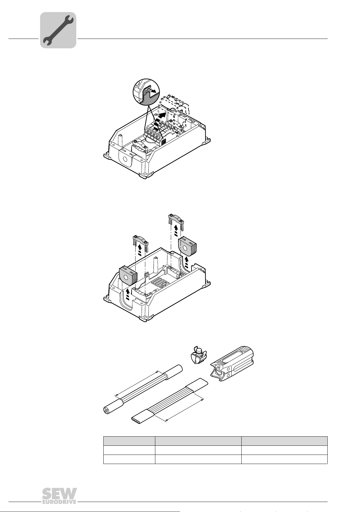
3. Pull both locking tabs to the outside and tilt up the upper part of the FieldPower
contact module.
2839866123
4. Loosen the 4 screws and remove the strain relief brackets.
Remove the two cable seals.
®
16
5. Remove the sheath of the line cable with a suitable stripping tool.
Line cable Stripping tool Strip length
Round cable AM 16 130 mm
Flat cable AMF 6/10 120 mm
Compact Operating Instructions – MOVIFIT® basic
2839868043
2839869963
Page 17
Electrical Installation
L1
N
L2
PE
L3
BK or 1
UL 1277
TC-ER
UL 62
STOOW
IEC
60757
BK or 2
WT or GY
GN/YE GN/YE
GY
BK or 3
BK
BK
BU
BR
WT
unused
GN
RD
Power bus connection (line cable)
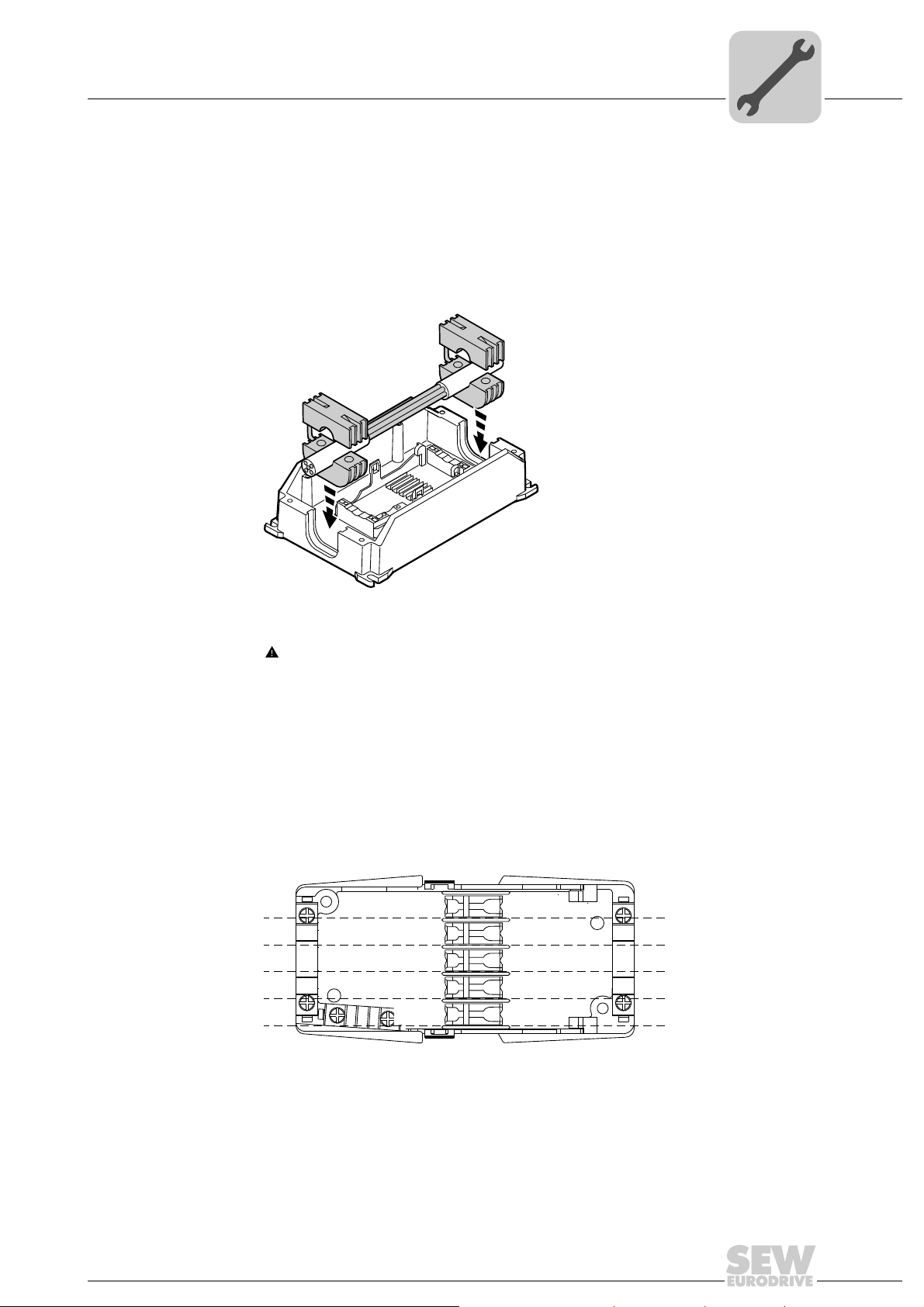
6. Fix the cable seals around the line cable.
NOTICE Ingression of moisture or dust due to incorrect cable seal.
Damage to the MOVIFIT
• Only use cable seals approved for the line cable diameter.
Insert the cable seals with the line cable in the recesses in the ABOX.
®
basic unit.
5
2839871883
7. WARNING Risk of crushing due to wrong sense of rotation or damage due to
reverse connection of phases.
Severe or fatal injuries, irreparable damage to the unit.
• Observe the following connection diagram.
• Prevent short circuits.
Insert the conductors of the line cable in the cable guides according to the following
wiring diagram:
Compact Operating Instructions – MOVIFIT® basic
2839873803
17
Page 18
5
90°
AB
Electrical Installation
Power bus connection (line cable)
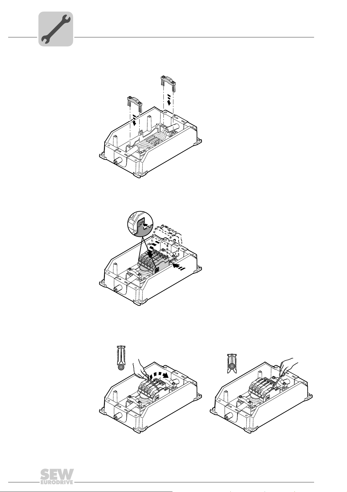
8. Screw the strain relief brackets to the ABOX and fix the line cable with the brackets
(tightening torque: 0.6 Nm, 5.3 lb.in).
2839875723
9. Place the upper part of the contact module on the hinge hooks.
Tilt down the upper part of the contact module until it latches on both sides.
2839877643
10.Use the screwdriver (blade width 3 – 3.5 mm) to lever the contacts of the insulation
displacement connector downwards.
18
Compact Operating Instructions – MOVIFIT® basic
2839879563
Page 19
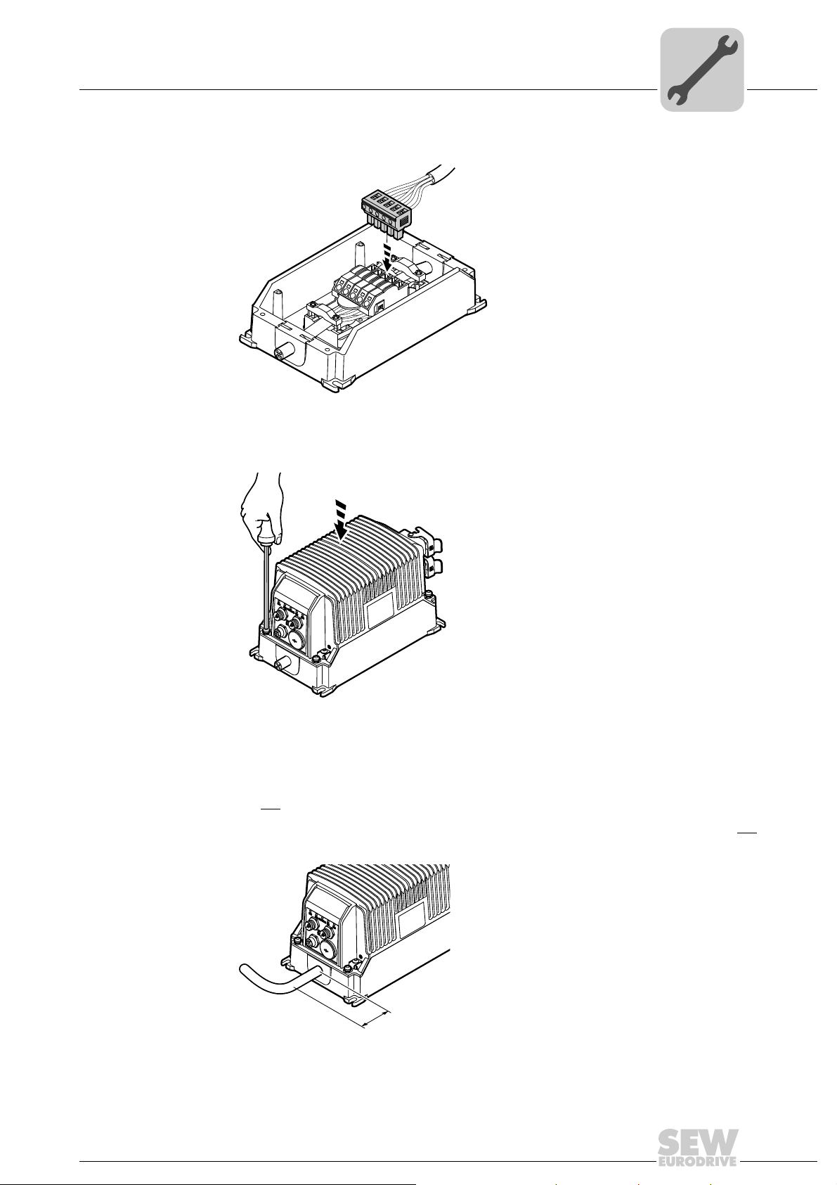
Electrical Installation
Power bus connection (line cable)
11.Plug in the line connector of the EBOX to the FieldPower® contact module.
2839881483
12.Position the EBOX on the ABOX.
Screw on the EBOX with 4 screws (tightening torque: 2 Nm, 18 lb.in).
5
NOTICE Ingression of moisture or dust when bending the line cable.
Damage to the MOVIFIT
• Do not
bend the line cable for at least 50 mm.
The MOVIFIT
bent within 50 mm of the unit.
®
®
basic unit.
basic unit only meets the IP54 requirements if the line cable is not
2839860363
3756680203
Compact Operating Instructions – MOVIFIT® basic
19
Page 20
5
[1]
X8
X9
[2]
[1]
X8
X9
Electrical Installation
Motor connection
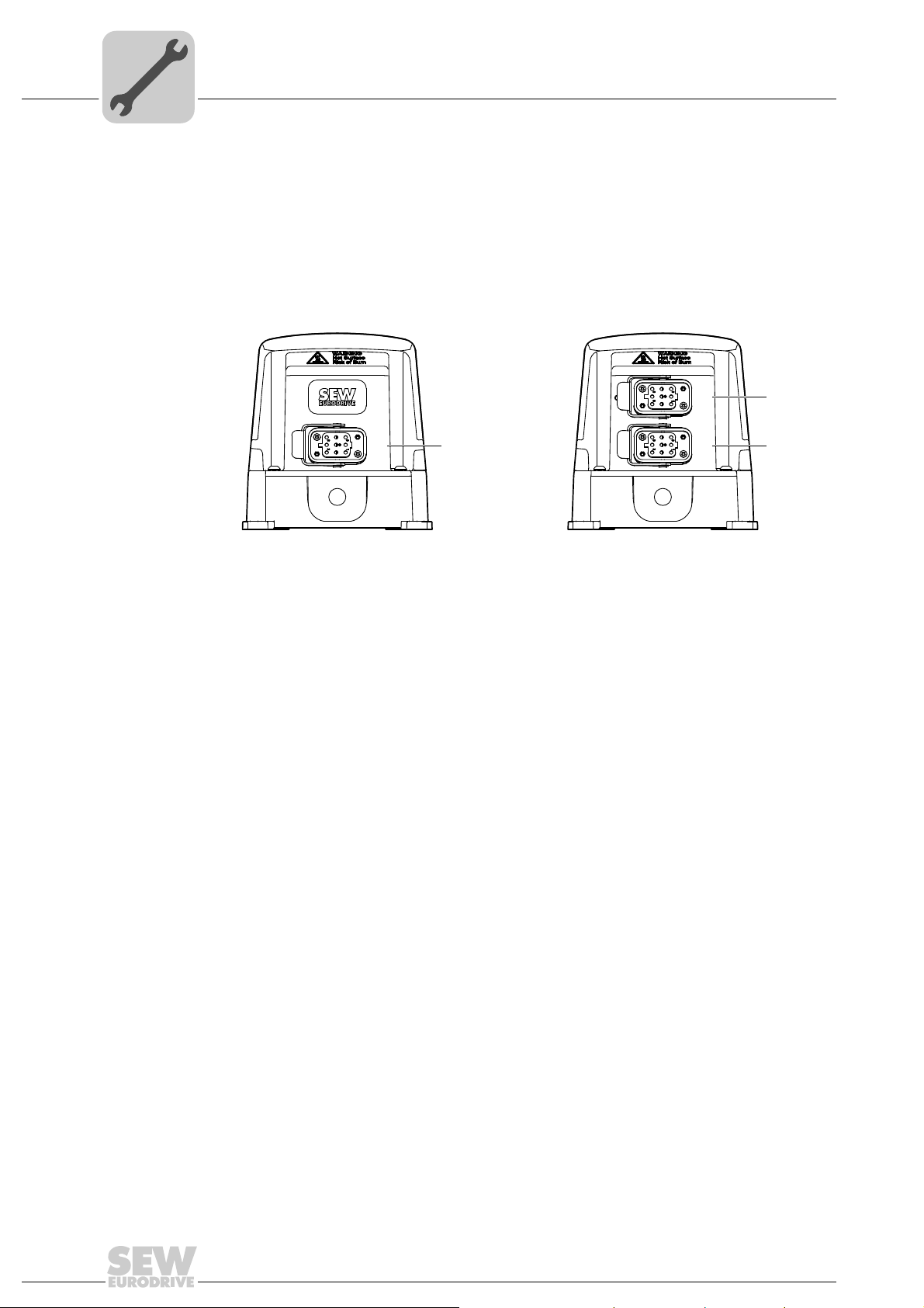
5.3 Motor connection
5.3.1 Motor connection variants
The following figure shows the motor plug connector variants for MOVIFIT
®
basic:
MOVIFIT
MOVIFIT
[1] X9 Motor connection
[2] X8 Motor connection
®
basic inverter
®
basic reversing starter
®
MOVIFIT
basic dual motor starter
(In preparation)
2816406795 2816404875
20
Compact Operating Instructions – MOVIFIT® basic
Page 21
Electrical Installation
8
5
3
1
2
4
PE
6
7
Motor connection
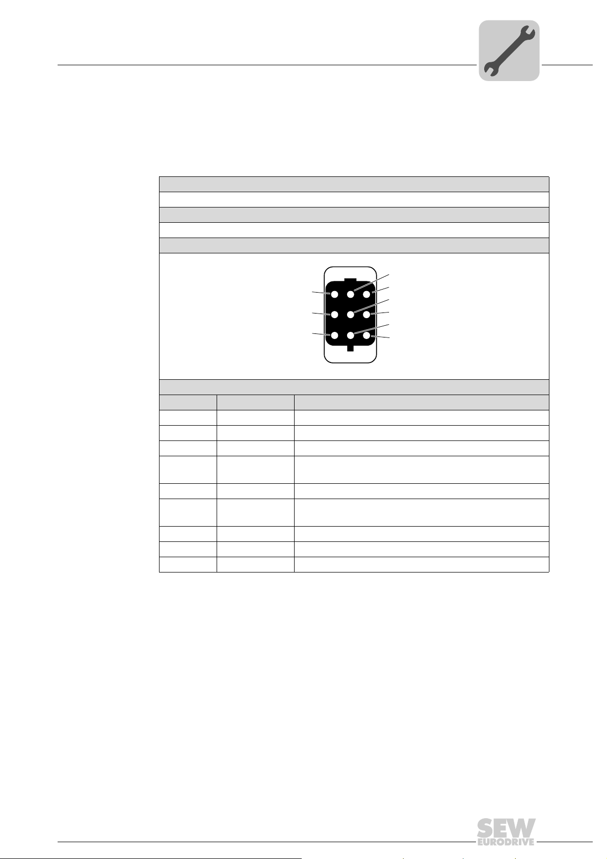
5.3.2 X9, (X8): Motor connection
The X8 plug connector is only available in conjunction with MOVIFIT
motor starter
Connection The following table provides information about this connection:
Function
Power connection for motor with brake
Connection type
Q 8/0, female
Wiring diagram
®
basic with dual-
5
Assignment
No. Name Function
1 U Motor phase U output
2 n. c. Not connected
3 W Motor phase W output
4 L1 Supply of mechanical brake
(only with MOVIFIT
5 n. c. Not connected
6 L2_S Supply of mechanical brake switched
(only with MOVIFIT
7 V Motor phase V output
8 n. c. Not connected
PE PE Protective earth
®
basic inverter)
®
basic inverter)
2441429259
Compact Operating Instructions – MOVIFIT® basic
21
Page 22
5
DI3 DI2 DI1 DI0
STATUS
[5]
[8] [7]
[6]
Electrical Installation
Control unit connection
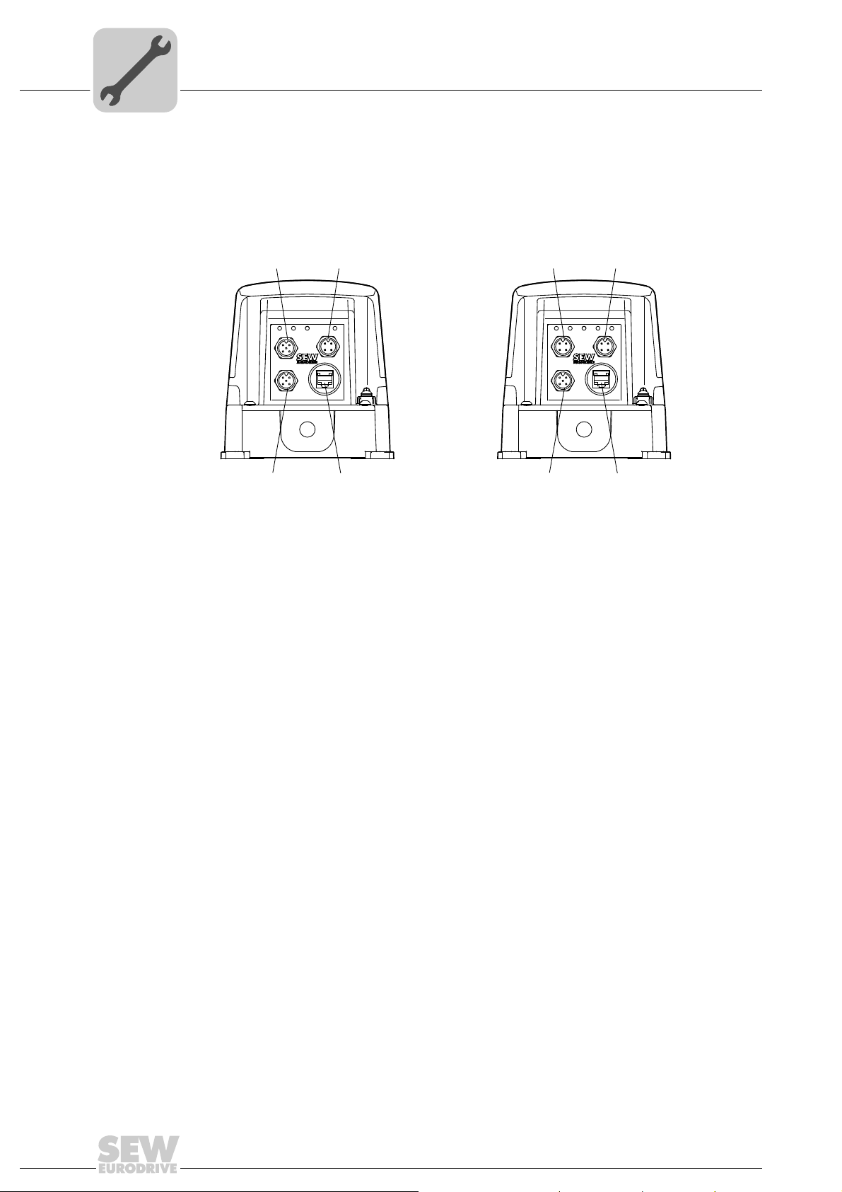
5.4 Control unit connection
The following figure shows the control unit variants for MOVIFIT®basic:
MOVIFIT
®
basic with AS-Interface MOVIFIT®basic with binary control
[1]
DI3 DI2
[4] [3]
STATUS
[2]
AS-Interface
9007202071153547 2816402955
[1] X22 Binary input sensor 2 [5] X12 Signal inputs DI2 + DI3
[2] X21 AS-Interface connection [6] X11 Signal inputs DI0 + DI1
[3] X50 Diagnostic interface [7] X50 Diagnostic interface
[4] X23 Binary input sensor 3 [8] X13 Signal outputs DO0 + DO1
22
Compact Operating Instructions – MOVIFIT® basic
Page 23
Electrical Installation
2
1
4
3
Connections of MOVIFIT®basic with AS-Interface
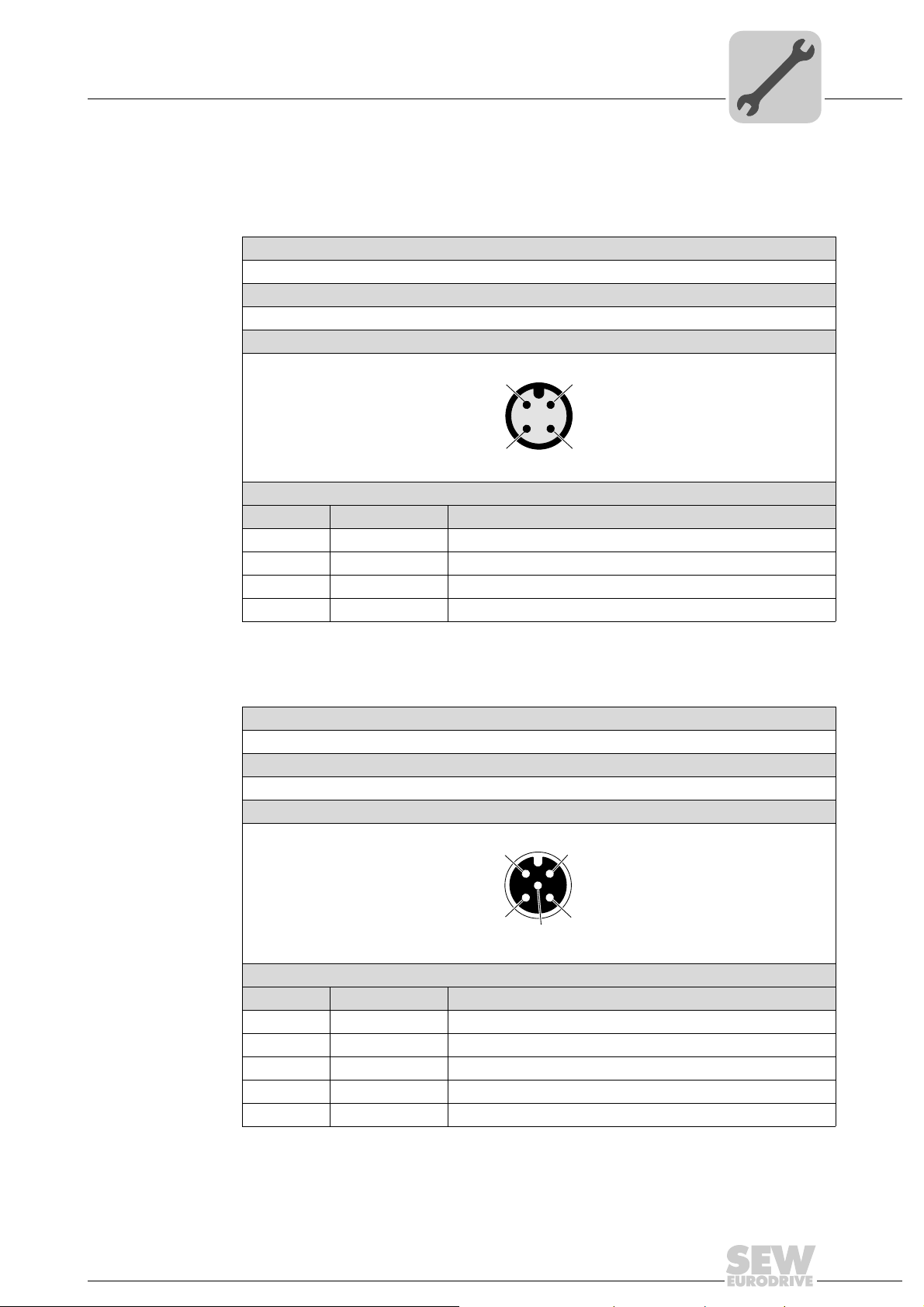
5.5 Connections of MOVIFIT®basic with AS-Interface
5.5.1 X21: AS-Interface connection
The following table provides information about this connection:
Function
AS-Interface – input
Connection type
M12, 4-pole, male, A-coded
Wiring diagram
Assignment
No. Name Function
1 AS-Interface + AS-Interface +
2 n. c. Not connected
3 AS-Interface − AS-Interface −
4 n. c. Not connected
5
2384154763
5.5.2 X22: Binary input sensor 2
The following table provides information about this connection:
Function
Binary input sensor 2
Connection type
M12, 5-pole, female, A-coded
Wiring diagram
Assignment
No. Name Function
1 +24 V DC 24 V output (sensor supply)
2 n. c. Not connected
3 0V24 0V24 reference potential
4 DI2 Binary input sensor 2
5 PE Equipotential bonding/protective earth conductor
1
4
2
3
5
2264816267
Compact Operating Instructions – MOVIFIT® basic
23
Page 24
5
1
6
Electrical Installation
Connections of MOVIFIT®basic with AS-Interface
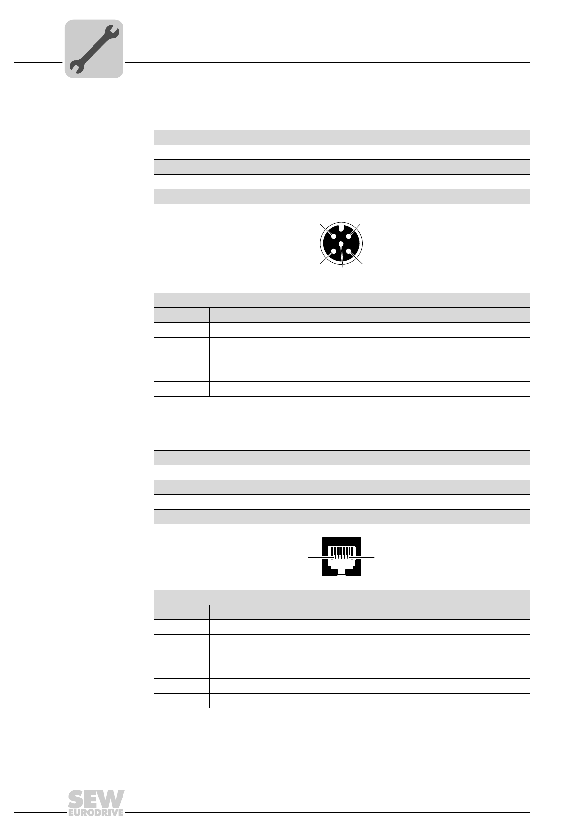
5.5.3 X23: Binary input sensor 3
The following table provides information about this connection:
Function
Binary input sensor 3
Connection type
M12, 5-pole, female, A-coded
Wiring diagram
Assignment
No. Name Function
1 +24 V DC 24 V output (sensor supply)
2 n. c. Not connected
3 0V24 0V24 reference potential
4 DI3 Binary input sensor 3
5 PE Equipotential bonding/protective earth conductor
5.5.4 X50: Diagnostic interface
The following table provides information about this connection:
Function
Diagnostics and programming interface
Connection type
RJ11 (6P6C)
Wiring diagram
1
4
2
3
5
2264816267
3163123211
Assignment
No. Name Function
1 n. c. Not connected
2 RS+ RS-485 data cable (+)
3RS − RS-485 data cable (–)
4 +24 V DC 24 V output for keypad
5 0V24 0V24 reference potential for keypad
6 n. c. Not connected
24
Compact Operating Instructions – MOVIFIT® basic
Page 25
Electrical Installation
2
1
4
3
2
1
4
3
Connections of MOVIFIT®basic with binary control
5.6 Connections of MOVIFIT®basic with binary control
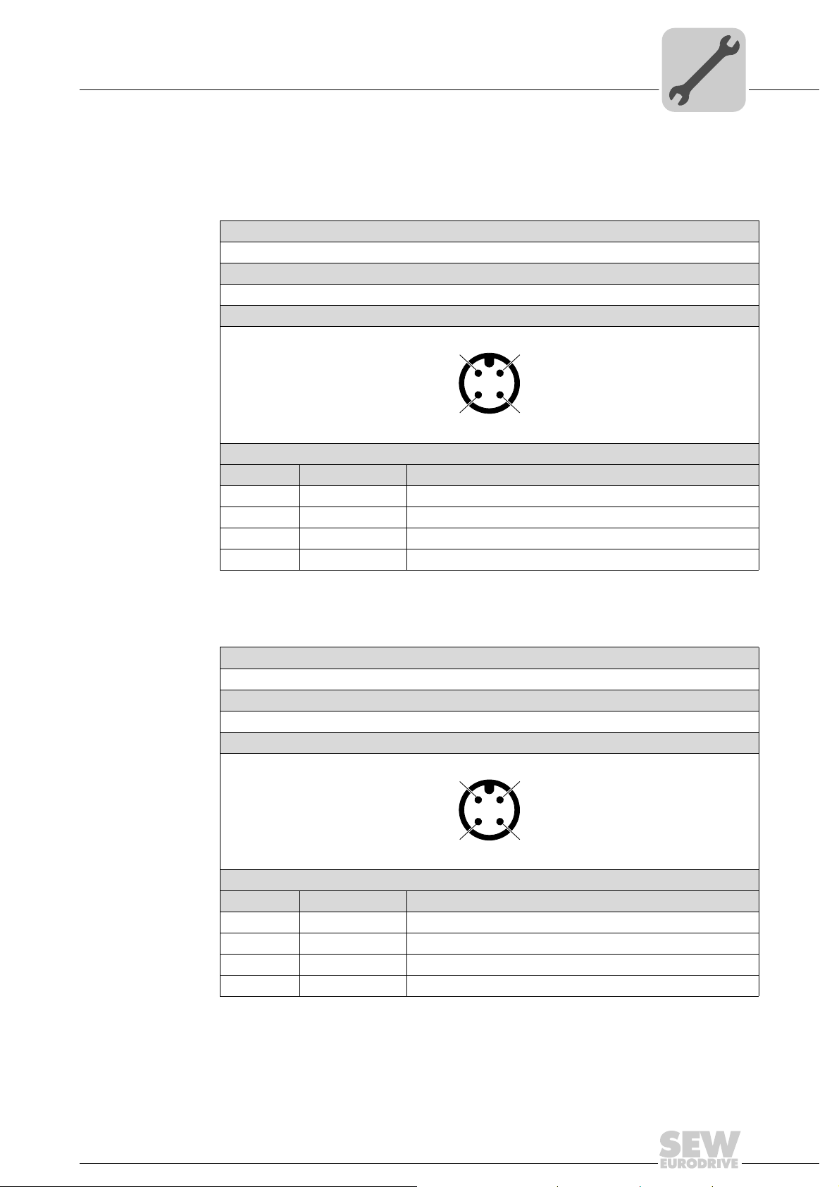
5.6.1 X11: Signal inputs 0 and 1 of MOVIFIT® basic
The following table provides information about this connection:
Function
Binary inputs 0 and 1
Connection type
M12, 4-pole, male, A-coded
Wiring diagram
Assignment
No. Name Function
1 n. c. Not connected
2 DI1 Binary input 1
3 0V24 0V24 reference potential
4 DI0 Binary input 0
5
2718233355
5.6.2 X12: Signal inputs 2 and 3 of MOVIFIT
The following table provides information about this connection:
Function
Binary inputs 2 and 3
Connection type
M12, 4-pole, male, A-coded
Wiring diagram
Assignment
No. Name Function
1 n. c. Not connected
2 DI3 Binary input 3
3 0V24 0V24 reference potential
4 DI2 Binary input 2
®
basic
2718233355
Compact Operating Instructions – MOVIFIT® basic
25
Page 26
5
1
4
3
2
5
1
6
Electrical Installation
Connections of MOVIFIT®basic with binary control
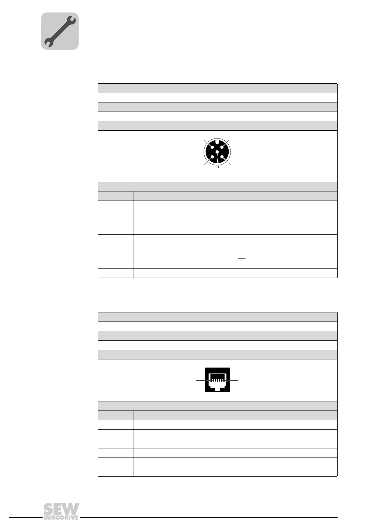
5.6.3 X13: Signal outputs 0 and 1 of MOVIFIT® basic
The following table informs about this connection:
Function
Binary outputs 0 and 1
Connection type
M12, 5-pole, female, A-coded
Wiring diagram
Assignment
No. Name Function
1 +24 V DC 24 V output
2 DO1 Binary output 1 (manual mode)
3 0V24 0V24 reference potential
4 DO0 Binary output 0 (ready signal)
5 PE Equipotential bonding/protective earth conductor
0: MOVIFIT
1: Manual control of MOVIFIT
0: MOVIFIT
1: MOVIFIT
®
basic control via control signals
®
basic is not ready
®
basic is ready
®
2264816267
basic
5.6.4 X50: Diagnostic interface
The following table informs about this connection:
Function
Diagnostics and programming interface
Connection type
RJ11 (6P6C)
Wiring diagram
Assignment
No. Name Function
1 n. c. Not connected
2 RS+ RS-485 data line (+)
3RS − RS-485 data cable (–)
4 +24 V DC 24 V output for keypad
5 0V24 0V24 reference potential for keypad
6 n. c. Not connected
3163123211
26
Compact Operating Instructions – MOVIFIT® basic
Page 27
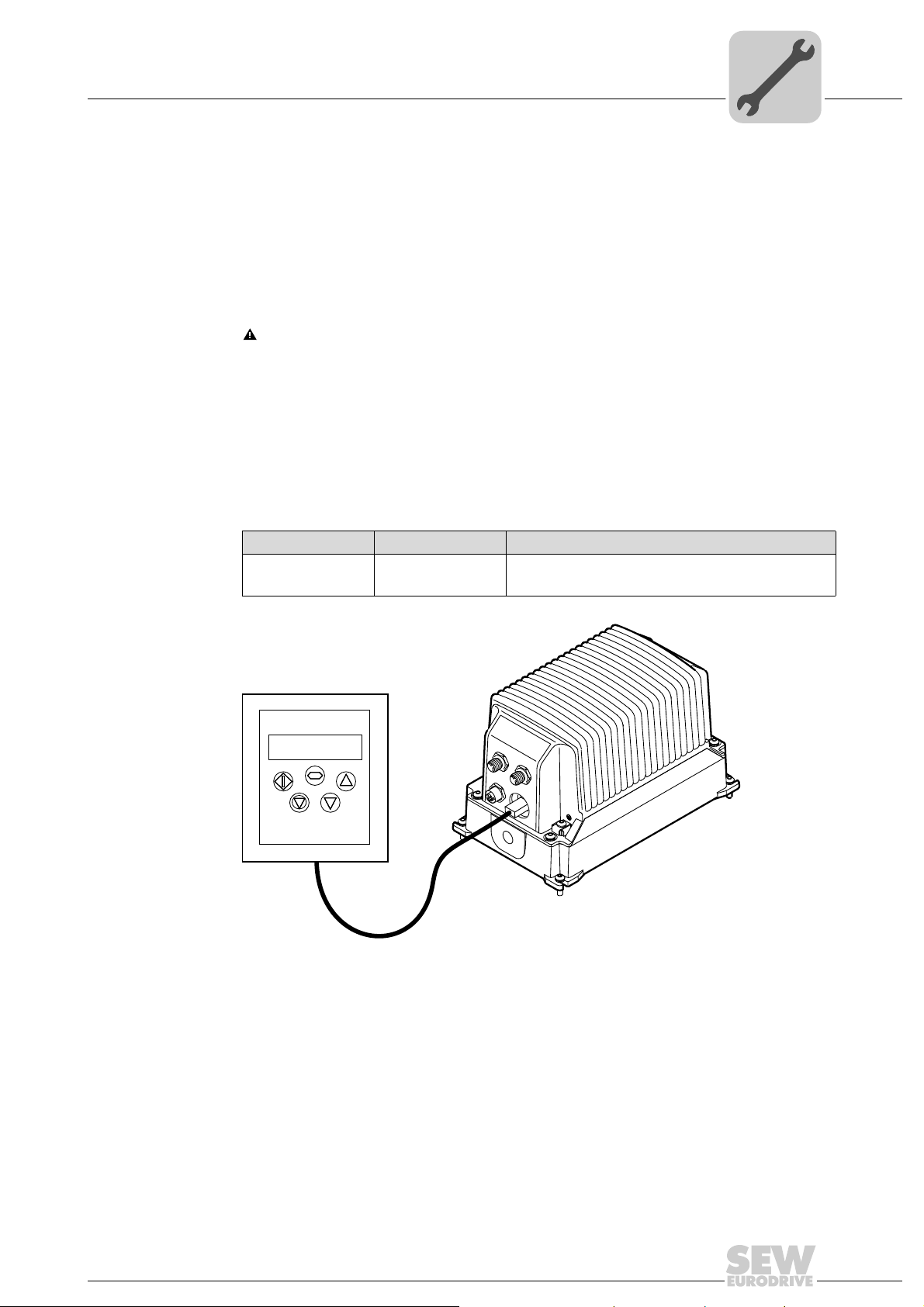
5.7 Connection of LT-BG keypad
The MOVIFIT® basic inverter is equipped with an X50 diagnostic interface (RJ-11
socket) for startup, parameterization and service.
The diagnostic interface is located in the connection block of the control unit.
You must remove the screw plug before plugging in the connector into the diagnostic
interface.
DANGER Danger of burns due to hot surfaces of the MOVIFIT
Severe injuries.
• Wait for the MOVIFIT
Use the cable enclosed with the keypad to connect the keypad to the MOVIFIT
unit.
Electrical Installation
Connection of LT-BG keypad
®
basic unit.
®
drive to cool down sufficiently before touching it.
®
basic
5
Scope of delivery:
Type Part number Scope of delivery
LT-BG 1 820 864 9 – LT-BG keypad
– Cable with RJ11 – RJ11 plug connectors
9007202071155467
Compact Operating Instructions – MOVIFIT® basic
27
Page 28
6
00
I
Startup
Important startup notes
6Startup
6.1 Important startup notes
INFORMATION
You must comply with the general safety notes in chapter "Safety Notes" during
startup.
Risk of crushing due to missing or defective protective covers.
Severe or fatal injuries.
• Install the protective covers of the plant according to the instructions, also see the
• Never start up the drive if the protective covers are not installed.
Electric shock due to dangerous voltages in the ABOX.
Severe or fatal injuries.
• De-energize the MOVIFIT
• Secure the MOVIFIT
• Wait for at least 10 minutes before removing the EBOX.
WARNING
operating instructions of the gear unit.
WARNING
®
basic unit using a suitable external cut-off device
before removing the EBOX.
supply.
®
basic unit against unintended re-connection to the voltage
WARNING
Danger of burns due to hot surfaces of the MOVIFIT® basic unit.
Severe injuries.
• Do not touch the MOVIFIT
®
basic until it has cooled down sufficiently.
Warning
Unit malfunction due to incorrect unit setting.
Severe or fatal injuries.
• Observe the startup instructions.
• The installation must only be carried out by qualified personnel.
• Only use settings that are consistent with the function.
INFORMATION
To ensure fault-free operation, do not disconnect or connect power or signal cables
during operation.
28
Compact Operating Instructions – MOVIFIT® basic
Page 29
Startup procedure for the MOVIFIT® basic inverter
00
I
6.2 Startup procedure for the MOVIFIT® basic inverter
Proceed as follows to startup the MOVIFIT® basic inverter:
1. Check the connection of the MOVIFIT
See chapter "Electrical Installation".
2. Make sure that the motor cannot start
e.g. by unplugging the motor connector(s) from the MOVIFIT
3. Switch on the line voltage.
The "Status" LED is now illuminated.
4. Connect the LT-BG keypad to the MOVIFIT
See chapter "LT-BG keypad connection" (page 27).
WARNING During the auto-tune phase in vector control, the motor axis briefly
rotates.
If you set the parameter P4-02 Auto-tune = "1", the inverter performs a calibration
process (Auto-tune). The inverter releases the brake and the motor briefly rotates.
Severe injuries.
• During the auto-tune phase, observe a sufficient safety distance to all parts driven
by the motor.
®
basic unit.
®
basic unit.
Startup
®
basic unit.
6
5. Set the following parameters:
Motor parameters:
For V/f control
• P1-07 = Nominal motor voltage
• P1-08 = Nominal motor current
• P1-09 = Nominal motor frequency
System parameters:
• P1-03 = Acceleration ramp
• P1-04 = Deceleration ramp
• P1-11 = Speed n1
• P2-02 = Speed n2
• P2-03 = Speed n3
• P2-04 = Speed n4
See chapter "Parameter setting" (page 32)
6. NOTICE Loss of the ensured degree of protection if the screw plug of the diagnostics
interface is not installed or not installed correctly.
Damage to the MOVIFIT
• Make sure the screw plug of the diagnostics interface has a seal and screw it in.
7. Switch off the line voltage.
8. Set the AS-Interface slave address of the MOVIFIT
basic with AS-Interface).
®
basic unit
For vector control
• P1-07 = Nominal motor voltage
• P1-08 = Nominal motor current
• P1-09 = Nominal motor frequency
• P4-01 = Control mode
• P4-02 = Auto-tune
• P4-05 = motor power factor
®
basic unit (only for MOVIFIT
®
9. Start up the higher-level controller.
10.Plug in the motor connector(s) at MOVIFIT
11.Switch on the line voltage.
Compact Operating Instructions – MOVIFIT® basic
®
basic.
29
Page 30
6
00
I
Startup
MOVIFIT® basic motor starter – startup procedure
6.3 MOVIFIT® basic motor starter – startup procedure
WARNING
Electric shock due to dangerous voltages in the ABOX.
Severe or fatal injuries.
• De-energize the MOVIFIT
before removing the EBOX.
• Secure the MOVIFIT
supply.
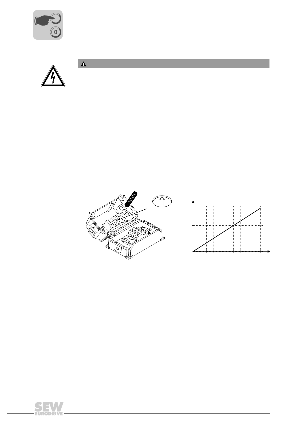
Proceed as follows to startup the MOVIFIT® basic motor starter:
1. Check the connection of the MOVIFIT
See chapter "Electrical Installation".
2. Set the nominal motor current via the potentiometer I
nameplate, factory setting: about 100%.
®
basic unit using a suitable external cut-off device
®
basic unit against unintended re-connection to the voltage
®
basic unit.
according to the motor
Motor
NOTICE Damage due to incorrect setting via potentiometer I
is to protect the motor against overload.
Damage to the motor.
• Set the nominal motor current via the potentiometer I
motor nameplate.
60
40
20
[1] Potentiometer setting
80
100
I [A]
Motor
10
8
6
4
2
0
0 20 40 60 80 100
3. Make sure that the motor cannot start
e.g. by unplugging the motor connector(s) from the MOVIFIT
4. Set the AS-Interface slave address of the MOVIFIT
®
basic with AS-Interface).
. The potentiometer
Motor
according to the
Motor
3759803915
®
basic unit.
basic unit (only for MOVIFIT
[1]
®
30
5. Start up the higher-level controller.
6. Plug in the motor connector(s) at MOVIFIT
®
basic.
7. Switch on the line voltage.
Compact Operating Instructions – MOVIFIT® basic
Page 31
Startup
00
I
Parameterization with LT-BG keypad
6.4 Parameterization with LT-BG keypad
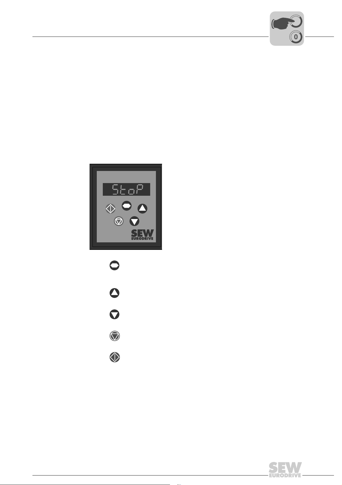
6.4.1 Description of LT-BG keypad
Function You can use the LT-BG keypad for startup, parameterization and manual operation of
MOVIFIT
about the state of the drive.
Features • Illuminated display
• Keypad with 5 keys
• Connection cable
Key assignment The following figure shows the key assignment of the LT-BG keypad:
®
basic inverters. In addition to that, the keypad displays important information
6
Key Navigate • Switch menu
• Saving parameter values
• Show real-time information
Key Up • Increase speed
• Increase parameter values
Key Down • Decrease speed
• Decrease parameter values
Key Stop • Stop drive
• Resetting the drive
Key Start • Enabling the drive
• Changing the direction of rotation
2669822603
Compact Operating Instructions – MOVIFIT® basic
31
Page 32
6
00
I
6.4.2 Parameterization
Startup
Parameterization with LT-BG keypad
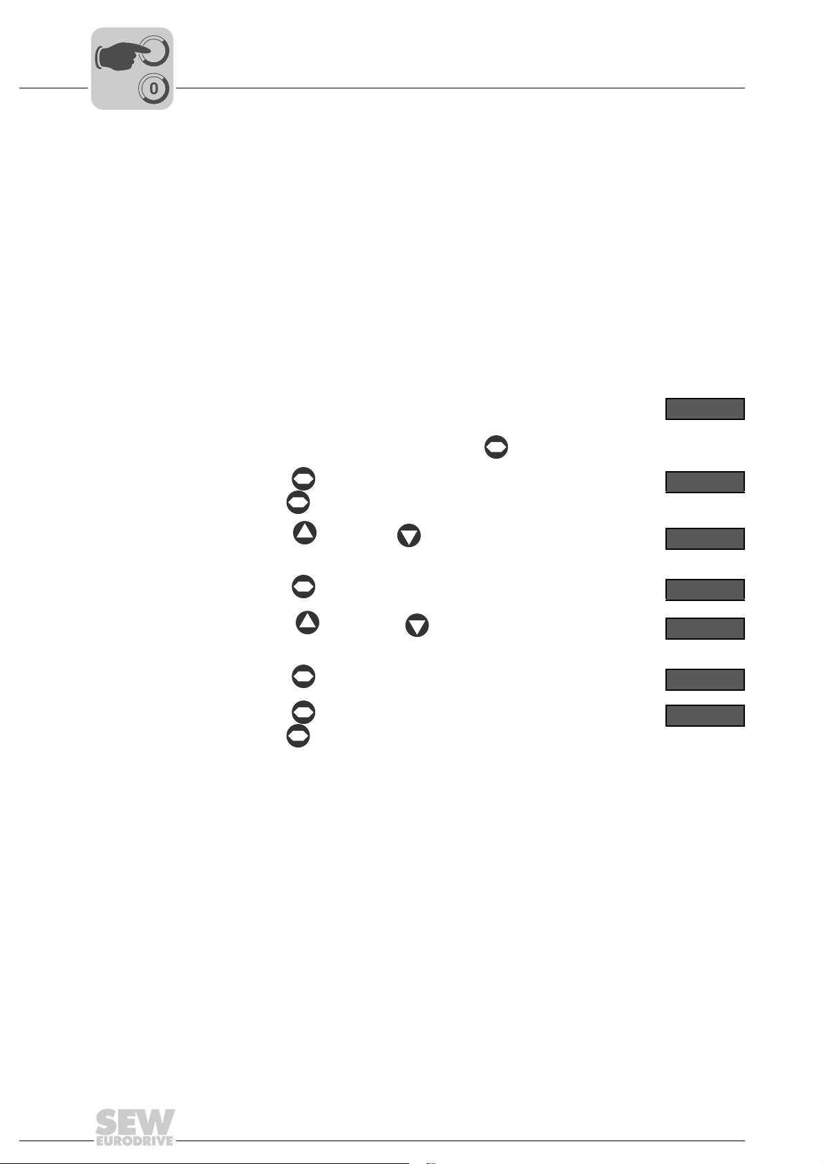
Proceed as follows to change the parameter values:
1. Check the connection of the MOVIFIT
See chapter "Electrical Installation".
®
basic unit.
2. Connect the LT-BG keypad to the MOVIFIT
See chapter "LT-BG keypad connection" (page 27).
3. Make sure that the motor cannot start
e.g. by unplugging the motor connector(s) from the MOVIFIT
4. Switch on the line voltage.
After initialization, the keypad shows the rotational frequency "H",
the output current "A", or the motor power "P".
To change the display, briefly press the key.
5. Use the key to activate the parameter mode.
( press key for more than 1 s)
6. Use the key and the key to select the desired parameter.
7. Use the key to activate the setting mode.
8. Use the key and the key to set the required parameter
value.
®
basic unit.
®
basic unit.
H 50.0
P 1 - 0 1
P 1 - 0 3
5.0
2.0
9. Use the key to quit the setting mode.
10. Use the key to quit the parameter mode.
( press key for more than 1 s)
The keypad shows "StoP", "H ", "A ", or "P ".
11. Switch off the line voltage.
12. Plug in the motor connector(s) at the MOVIFIT
13. NOTICE Damage due to missing or incorrectly mounted screw plug of the diagnostic interface X50. The degree of protection of MOVIFIT
"Technical Data" only applies if the screw plug of the diagnostic interface is mounted
correctly.
Damage to the MOVIFIT
• Once you have finished working with the keypad, unplug the connector from the
diagnostic interface.
• Screw the screw plug of the diagnostics interface back in with the seal.
For a description of the parameters, refer to chapter "Parameter list – MOVIFIT
inverter" in the detailed operating instructions.
®
basic unit.
®
basic unit.
®
basic specified in section
P 1 - 0 3
S t o P
®
basic
32
Compact Operating Instructions – MOVIFIT® basic
Page 33
Functions of MOVIFIT® basic with AS-Interface
00
I
6.5 Functions of MOVIFIT® basic with AS-Interface
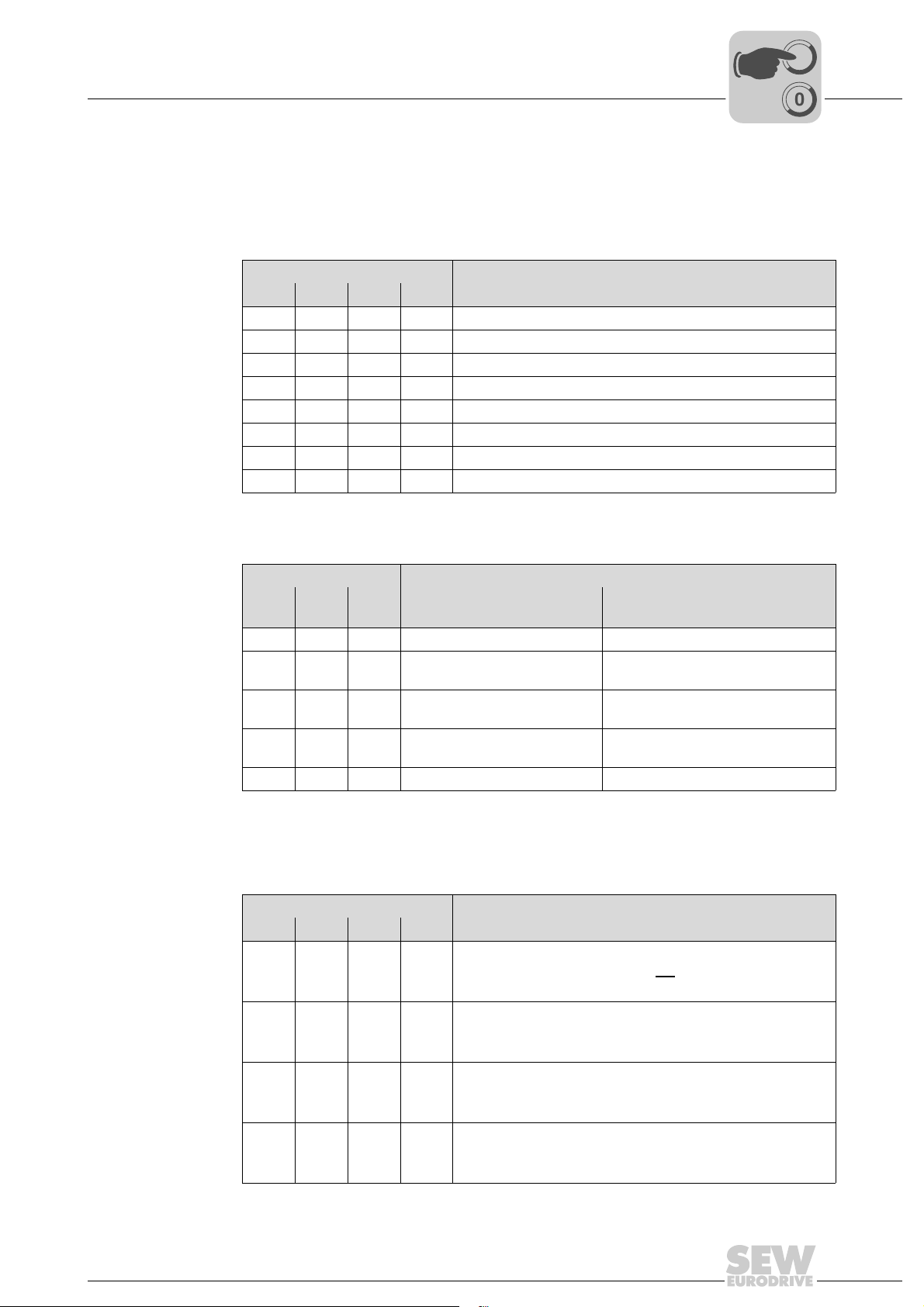
6.5.1 Data transfer AS-Interface master → MOVIFIT® basic
MOVIFIT
inverter
®
basic
The following table shows the 4 data bits that the AS-Interface master sends to the
MOVIFIT
DO3 DO2 DO1 DO0 MOVIFIT® basic inverter
®
basic inverter and the functions of the drive:
AS-Interface bit Function
XX0 0 Stop
X X 0 1 Enable CW
X X 1 0 Enable CCW
X X 1 1 Stop/reset
0 0 X X Setpoint speed = n1
0 1 X X Setpoint speed = n2
1 0 X X Setpoint speed = n3
1 1 X X Setpoint speed = n4
Startup
6
MOVIFIT
motor starter
®
basic
The following table shows the 4 data bits that the AS-Interface master sends to the
MOVIFIT
AS-Interface bit Function
DO2 DO1 DO0 MOVIFIT® basic
0 0 0 Stop Stop
001
010
011
1 X X Reset Reset
6.5.2 Data transfer MOVIFIT
The following table shows the 4 data bits that MOVIFIT
Interface master:
DI3 DI2 DI1 DI0
X X X 1 / 0
XX1 / 0X
X 1 / 0 X X
1 / 0 X X X
X = any status
®
basic motor starter and the functions of the drive:
Reversing starter
Enable CW Enable signal for motor at terminal
Enable CCW Enable signal for motor at terminal
Stop Enable signal for both motors at X9
®
basic → AS-Interface master
AS-Interface bit Meaning
Ready signal
0: The MOVIFIT® basic drive is not ready
1: The MOVIFIT
Manual mode
0: MOVIFIT®basic control via AS-Interface
1: Manual control of MOVIFIT
Sensor input 2
0: The signal of sensor 2 = "0"
1: The signal of sensor 2 = "1"
Sensor input 3
0: Signal of sensor 3 = "0"
1: Signal of sensor 3 = "1"
®
basic drive is ready for operation
MOVIFIT® basic dual motor
starter
X9
X8
+ X8
®
basic sends back to the AS-
®
basic
Compact Operating Instructions – MOVIFIT® basic
33
Page 34
6
00
I
Startup
Functions of MOVIFIT® basic with binary control
6.6 Functions of MOVIFIT® basic with binary control
6.6.1 Data transfer PLC → MOVIFIT® basic
MOVIFIT
inverter
®
basic
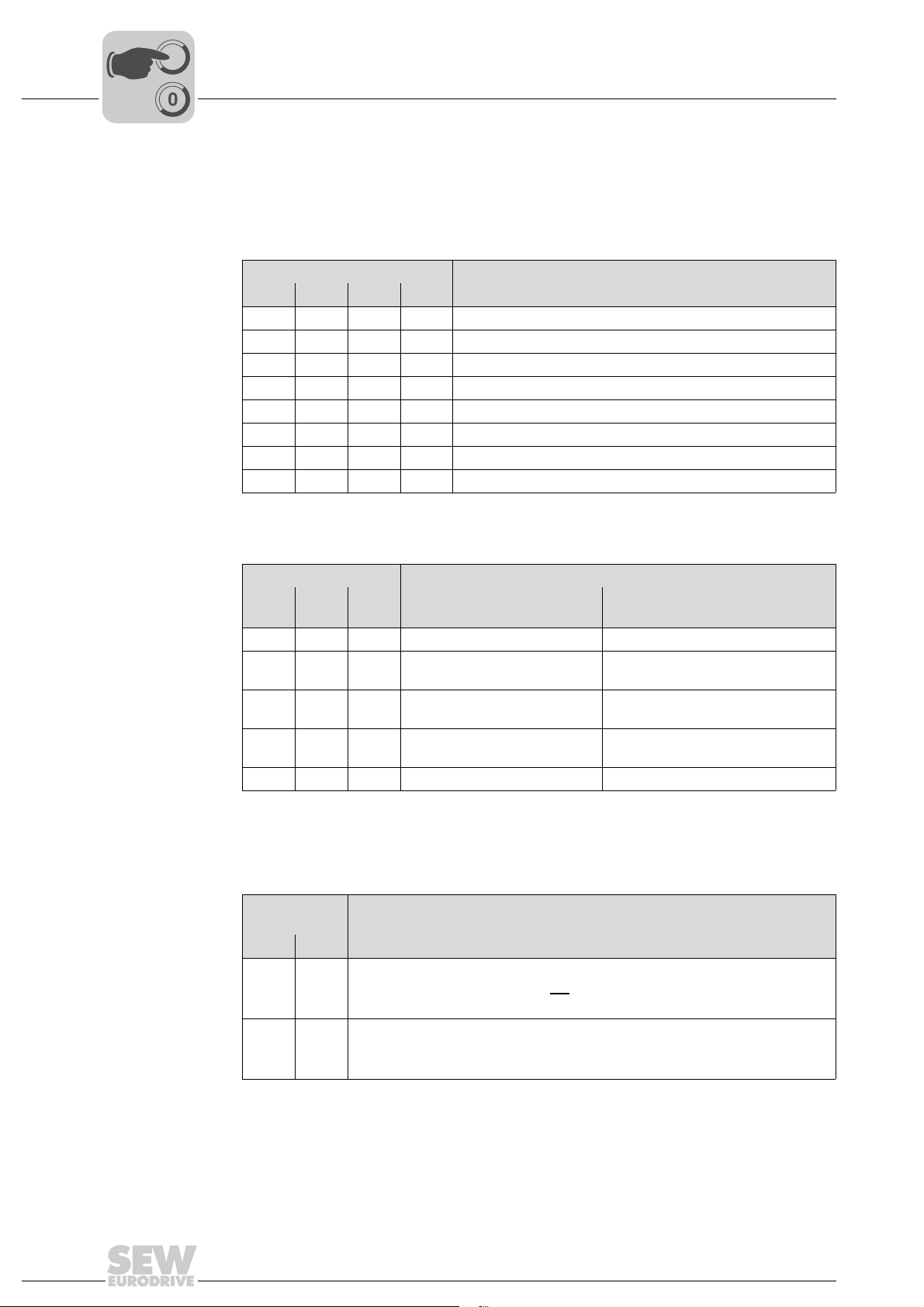
The following table shows the control signal that the higher-level controller (e.g. PLC)
sends to the MOVIFIT
Control signals Function
DI3 DI2 DI1 DI0 MOVIFIT® basic inverter
XX0 0 Stop
X X 0 1 Enable CW
X X 1 0 Enable CCW
X X 1 1 Stop/reset
0 0 X X Setpoint speed = n1
0 1 X X Setpoint speed = n2
1 0 X X Setpoint speed = n3
1 1 X X Setpoint speed = n4
®
basic inverter and the functions of the drive:
MOVIFIT
motor starter
®
basic
The following table shows the control signal that the higher-level controller (e.g. PLC)
sends to the MOVIFIT
Control signals Function
DI2 DI1 DI0 MOVIFIT® basic
0 0 0 Stop Stop
001
010
011
1 X X Reset Reset
6.6.2 Data transfer MOVIFIT
The following table shows the binary signals that MOVIFIT
higher-level controller (e.g. PLC):
Binary
signals
DO1 DO0
X 1 / 0
1 / 0 X
X = any status
®
basic → PLC
Meaning
Ready signal
0: The MOVIFIT® basic drive is not ready
1: The MOVIFIT
Manual mode
0: MOVIFIT
1: Manual control of MOVIFIT
®
basic motor starter and the functions of the drive:
MOVIFIT® basic
Reversing starter
Enable CW Enable signal for motor at terminal
Enable CCW Enable signal for motor at terminal
Stop Enable signal for both motors at X9
®
basic drive is ready for operation
®
basic control via control signals
®
basic
Dual motor starter
X9
X8
+ X8
®
basic sends back to the
34
Compact Operating Instructions – MOVIFIT® basic
Page 35
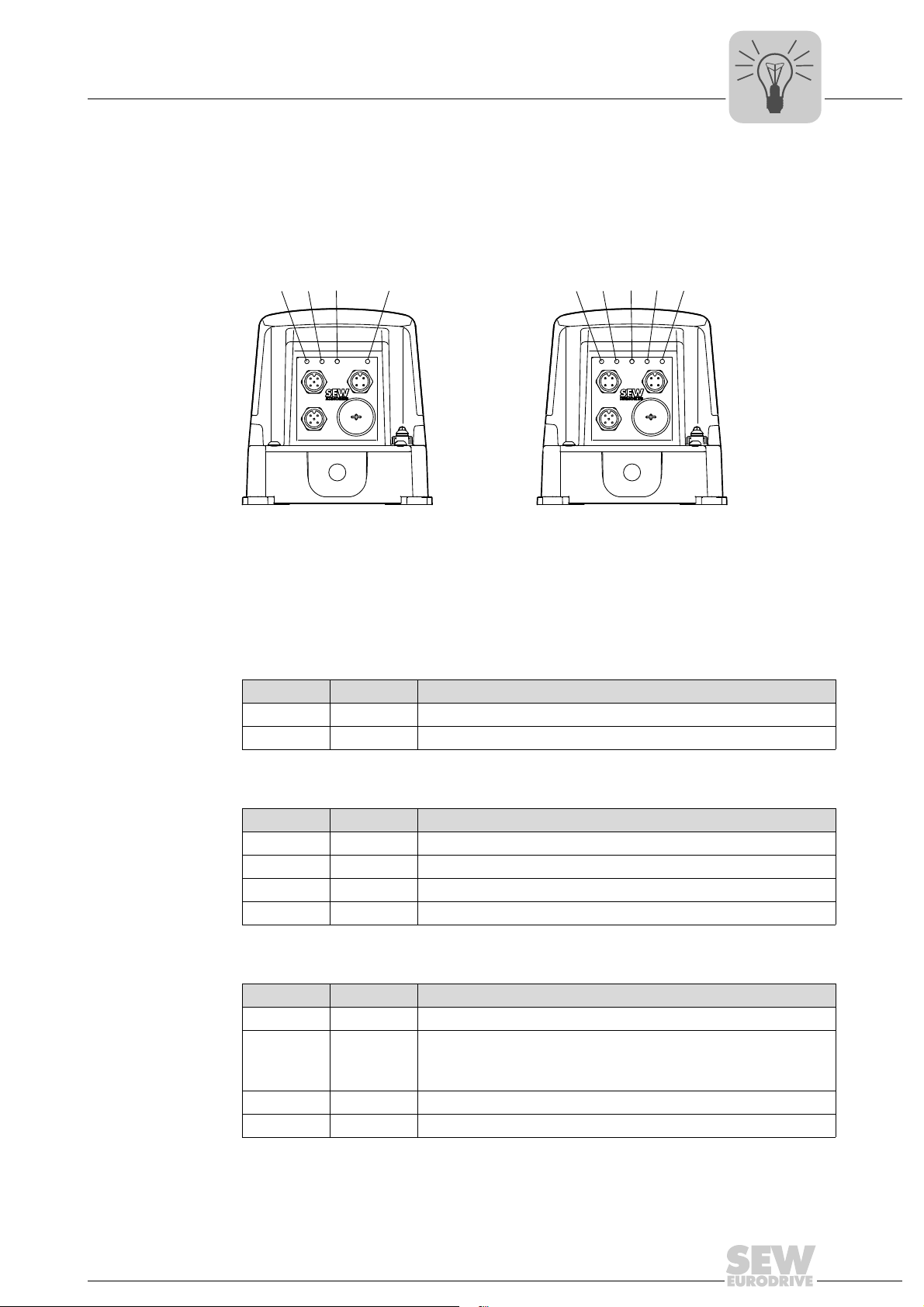
7 Operation
DI3 DI2 DI1 DI0
STATUS
[5] [6] [7] [8] [9]
7.1 Operating displays (LEDs)
The following figure shows the LEDs of MOVIFIT® basic:
MOVIFIT
®
basic with AS-Interface MOVIFIT®basic with binary control
[1] [2] [3] [4]
AS-Interface
STATUS
DI3 DI2
Operation
Operating displays (LEDs)
7
[1] LED "DI3" [5] LED "DI3"
[2] LED "DI2" [6] LED "DI2"
[3] LED "Status" [7] LED "Status"
[4] LED "AS-Interface" [8] LED "DI1"
7.1.1 LEDs "DI0 – DI3"
LED color LED status Meaning
– Off Input signal at binary input DI. open or "0"
Yellow Illuminated Input signal present at binary input DI.
7.1.2 LED "Status"
LED color LED status Meaning
– Off No voltage supply
Green Illuminated MOVIFIT
Yellow Illuminated MOVIFIT
Red Illuminated An error has occurred
7.1.3 LED "AS-Interface"
2816401035 2816399115
[9] LED "DI0"
®
basic drive is enabled
®
basic drive is ready for operation
Compact Operating Instructions – MOVIFIT® basic
LED color LED status Meaning
– Off No 24 V supply connected to the AS-Interface
Green Illuminated Normal mode
24 V supply connected to the AS-Interface OK
Communication present
Red Illuminated Communication interrupted or slave address is set to 0
Green/red Flashing Communication or peripheral error
35
Page 36
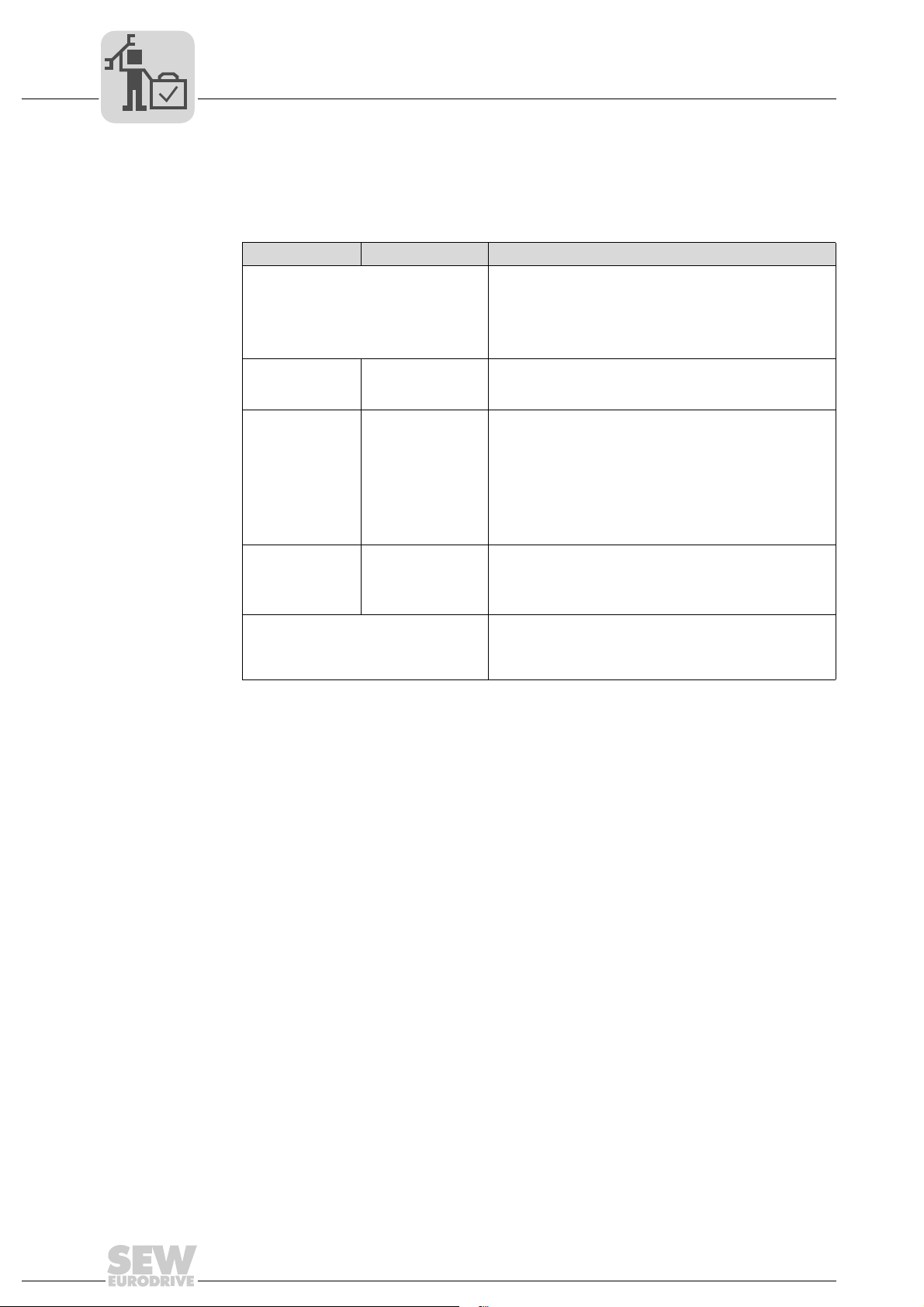
8
Service
Diagnostics with LT-BG keypad
8 Service
8.1 Diagnostics with LT-BG keypad
The following table helps you with troubleshooting:
Error Cause Solution
Overload or overcurrent error of the
unloaded motor during acceleration
The motor axis is
not rotating
Display remains
on "StoP"
The drive does
not start in very
cold environments
Drive does not run properly in vector
mode.
Overload or overcurrent
No enable signal
for the drive
Ambient temperature below −10 °C
• Check the star/delta terminal connection in the
motor.
The nominal operating voltages of motor and
MOVIFIT
The delta connection always yields the lower
voltage of a multi-voltage motor.
• Check whether the rotor of the motor is blocked.
• Make sure that the mechanical brake is released (if
installed).
• Check whether the enable signal from the higherlevel controller is present.
• Make sure the M12 connectors are plugged in
correctly.
• Check the parameter P1-12 for terminal control/
manual operation.
• Press the <Start> key while in manual mode. The
line voltage must correspond with the specified
values.
• Provide for a heat source that keeps the ambient
temperature of the drive above -10 °C.
• You must set the parameters P1-07, P1-08, and
P1-09 according to the data on the motor nameplate before starting the auto-tune process.
• Start auto-tune by setting P4-02 = "1".
®
basic must match.
36
Compact Operating Instructions – MOVIFIT® basic
Page 37
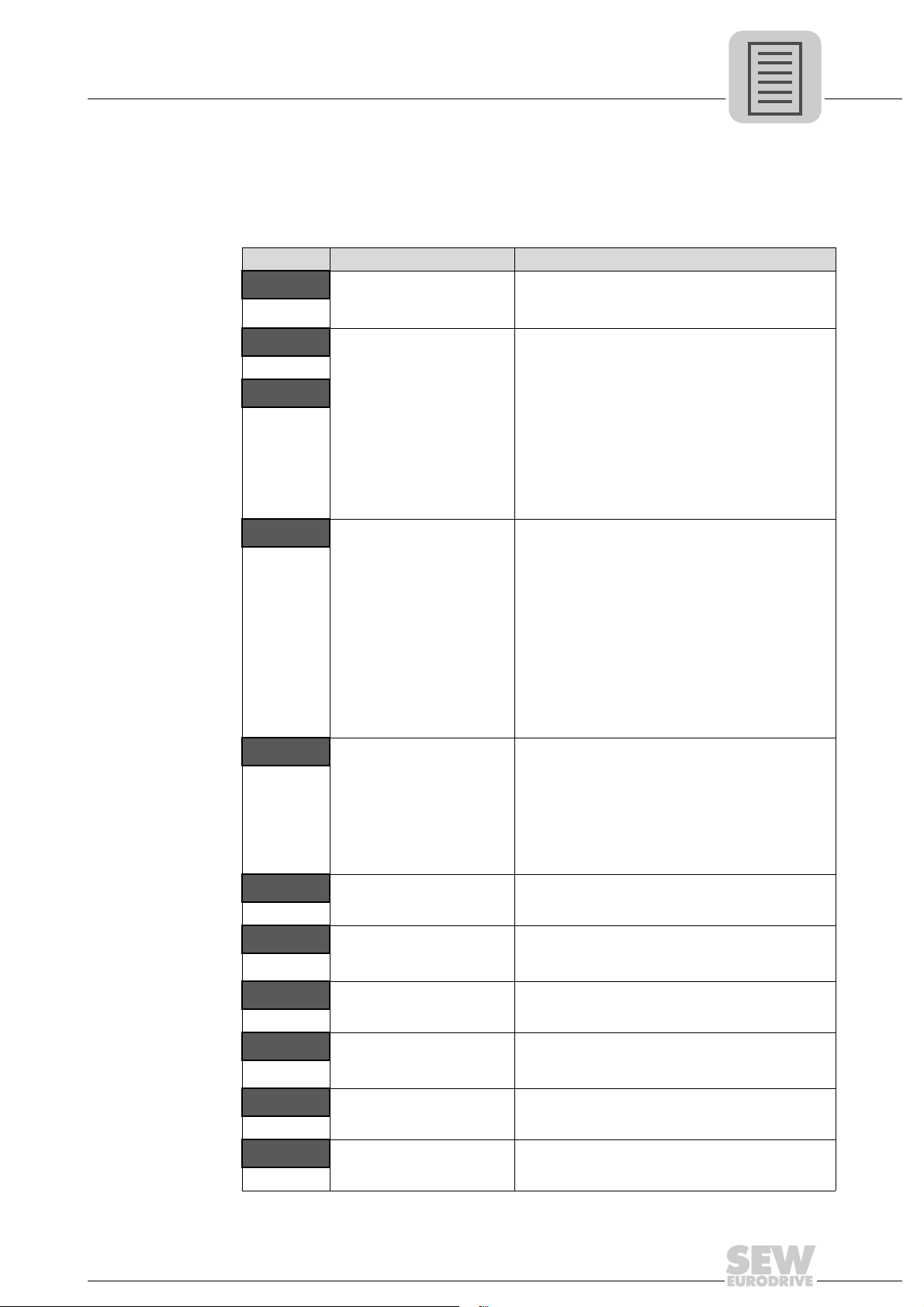
8.2 Error list of MOVIFIT® basic
The LT-BG keypad displays the errors that occurred at the MOVIFIT® basic drive. In
addition, you can read out the 4 latest errors from parameter P1-13 error protocol on the
PC.
Error code Error Solution
P-dEF
O-I
hO-I
I_ t-trP
PS-trP
O_Uo lt
U_Uo lt
O-t
U-t
th-Flt
The factory-set parameters
were loaded.
Overcurrent at inverter
output to the motor.
Motor overload.
Overtemperature at the
heat sink of the inverter.
An inverter overload error
occurs when the inverter
has delivered > 100% of the
nominal current for a certain
time (defined in P1-08). The
display is flashing to indicate the overload.
Internal output stage error Error when enabling the drive:
DC link overvoltage • Check whether the supply voltage is too high.
DC link undervoltage Occurs routinely when switching off the inverter.
Overtemperature at heat
sink
Undertemperature Occurs at an ambient temperature below -10 °C.
Faulty thermistor at heat
sink.
Service
Error list of MOVIFIT® basic
Press the <Stop> key.
The drive can now be configured for the desired
application.
• Check motor and connection cables for phase
short circuits or ground faults.
• Check load for blocking, stalling, or shock
loads.
• Make sure that the parameters P1-07, P1-08,
and P1-09 were set correctly according to the
motor nameplate.
• For vector control (P4-01 = "0" or "1"): Check
motor power factor in P4-05.
• Make sure that the auto-tune process for the
connected motor has been completed
successfully.
• Increase the ramp time in P1-03.
• Increase the acceleration ramp or reduce the
motor load.
• Make sure that the cable length meets the
requirements.
• Make sure that the parameters P1-07, P1-08,
and P1-09 were set correctly according to the
motor nameplate.
• In vector control mode (P4-01 = "0" or "1"),
check the motor power factor in P4-05.
• Make sure that the auto-tune process for the
connected motor has been completed
successfully.
• Check the load mechanically. Make sure that
the load can move freely and that there are no
blockages or other mechanical faults.
• Check for incorrect wiring or short circuit.
• Check for phase short circuits or ground faults.
Error during operation:
• Check for sudden overload or overtemperature.
• Provide additional space or cooling, if necessary.
• If the inverter switches off during deceleration,
increase the deceleration ramp in P1-04.
• Check line voltage if this occurs while the drive
is running.
• Check inverter cooling.
• Provide additional space or cooling, if necessary.
• Increase the ambient temperature to above 10 °C before switching on the inverter.
• Contact the SEW-EURODRIVE Service.
8
P-LOSS
Compact Operating Instructions – MOVIFIT® basic
Input phase failure error One input phase failed in an inverter designed for
operation on a three-phase system.
37
Page 38
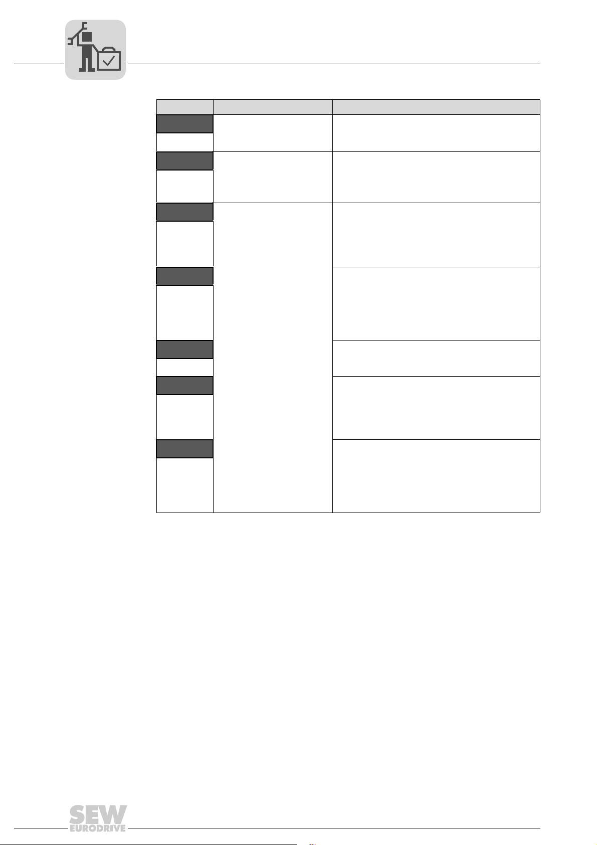
8
Service
Error list of MOVIFIT® basic
Error code Error Solution
Ph-lb
dAtA-F
At-FO1
Phase asymmetry Asymmetry of > 3% occurs for more than 30 s in
Internal memory error • Parameters not saved.
Auto-tune error The measured stator resistance of the motor
At-F02
At-F03
At-F04
At-F05
the supply input voltage.
• Check input voltage and fuses.
• Factory settings loaded.
• Try again.
• If this problem occurs repeatedly, contact the
SEW-EURODRIVE service.
fluctuates between the phases.
• Make sure that the motor is connected
correctly and without error.
• Check the winding for correct resistance and
symmetry.
The measured stator resistance of the motor is too
high.
• Make sure that the motor is connected
correctly.
• Check whether the power rating of the motor
corresponds with the power rating of the
connected inverter.
The measured motor inductivity is too low.
• Make sure that the motor is connected
correctly.
The measured motor inductivity is too high.
• Make sure that the motor is connected
correctly.
• Check whether the power rating of the motor
corresponds with the power rating of the
connected inverter.
The measured motor parameters are contradictory.
• Make sure that the motor is connected
correctly.
• Check whether the power rating of the motor
corresponds with the power rating of the
connected inverter.
38
Compact Operating Instructions – MOVIFIT® basic
Page 39

9 Declaration of Conformity
EC Declaration of Conformity
SEW-EURODRIVE GmbH & Co KG
Ernst-Blickle-Straße 42, D-76646 Bruchsal
declares under sole responsibility that the
units of the series MOVIFIT® basic MBF..
are in conformity with
Low Voltage Directive 2006/95/EC
Declaration of Conformity
MBS..
9
901120011
EMC Directive 2004/108/EC 4)
Applied harmonized standards EN 61800-5-1:2007
EN 60204-1:2006
EN 61800-3:2007
EN 55011:2007
4) According to the EMC Directive, the listed products are not independently operable products. EMC
assessment is only possible after these products have been integrated in an overall system. The
assessment was verified for a typical system constellation, but not for the individual product.
Bruchsal
Place Date Managing Director Technology a) b)
a) Authorized representative for issuing this declaration on behalf of the manufacturer
b) Authorized representative for compiling the technical documents
Compact Operating Instructions – MOVIFIT® basic
16.05.11
Johann Soder
3947025035
39
Page 40

SEW-EURODRIVE—Driving the world
SEW-EURODRIVE
Driving the world
SEW-EURODRIVE GmbH & Co KG
P.O. Box 3023
D-76642 Bruchsal/Germany
Phone +49 7251 75-0
Fax +49 7251 75-1970
[email protected]
www.sew-eurodrive.com
 Loading...