

SEW Movidrive mdx61b User Manual

Drive Technology \ Drive Automation \ System Integration \ Services
Manual
MOVIDRIVE
"
DriveSync via Fieldbus
®
MDX61B
"
Application
Edition 08/2010 17004411 / EN

SEW-EURODRIVE—Driving the world

Contents
Contents
1 General Information ............................................................................................ 6
1.1 Use of the manual....................................................................................... 6
1.2 Structure of the safety notes ....................................................................... 6
1.2.1 Meaning of the signal words ........................................................ 6
1.2.2 Structure of the section-related safety notes ............................... 6
1.2.3 Structure of the embedded safety notes...................................... 6
1.3 Right to claim under warranty ..................................................................... 7
1.4 Exclusion of liability..................................................................................... 7
1.5 Copyright..................................................................................................... 7
1.6 Applicable documentation........................................................................... 7
2 Safety Notes ........................................................................................................ 8
2.1 General information .................................................................................... 8
2.2 Designated use ........................................................................................... 8
2.3 Target group ............................................................................................... 8
2.4 Bus systems................................................................................................ 9
2.5 Operating mode "synchronous operation" .................................................. 9
3 System Description........................................................................................... 10
3.1 Areas of application .................................................................................. 10
3.2 Application examples ................................................................................ 11
3.2.1 Finite (linear) movement of the master and slave axis .............. 11
3.2.2 Finite (linear) movement of the slave
axis and infinite movement of the master axis........................... 12
3.2.3 Finite movements with master and slave axes .......................... 12
3.3 Program identification ............................................................................... 14
4 Project Planning................................................................................................ 15
4.1 Prerequisites ............................................................................................. 15
4.1.1 PC and software ........................................................................ 15
4.1.2 Inverters, motors and encoders ................................................. 15
4.1.3 Possible combinations ............................................................... 15
4.1.4 Additional notes ......................................................................... 15
4.2 Functional description ............................................................................... 16
4.2.1 Functional characteristics .......................................................... 16
4.2.2 Additional startup functions........................................................ 17
4.3 Scaling of the drive ................................................................................... 18
4.3.1 Drive without external encoder (positive connection) ................ 18
4.3.2 Drive with external encoder (non-positive connection) .............. 19
4.4 Limit switches, reference cams and machine zero ................................... 20
4.5 Process data assignment.......................................................................... 21
4.5.1 Process output data................................................................... 22
4.5.2 Process input data ..................................................................... 23
4.6 Software limit switches.............................................................................. 24
4.6.1 General information ................................................................... 24
4.6.2 Moving clear of the software limit switches................................ 24
4.7 Safe stop................................................................................................... 26
Manual – MOVIDRIVE® MDX61B "DriveSync via Fieldbus" Application
3

Contents
5 Installation ......................................................................................................... 27
5.1 MOVITOOLS
5.1.1 MOVITOOLS
5.1.2 Application variant ..................................................................... 27
5.2 Wiring diagram for incremental encoder master / MDX61B slave ............ 28
5.3 Wiring diagram for MDX61B master / MDX61B slave .............................. 29
5.4 MOVIDRIVE
5.4.1 Overview.................................................................................... 30
5.4.2 PROFIBUS (DFP21B) ............................................................... 31
5.4.3 INTERBUS with fiber optic cable (DFI21B) ............................... 32
5.4.4 INTERBUS (DFI11B) ................................................................. 33
5.4.5 CANopen (DFC11B) .................................................................. 34
5.4.6 DeviceNet (DFD11B) ................................................................. 35
5.4.7 Ethernet (DFE11B) .................................................................... 36
5.5 Connecting the system bus (SBus 1)........................................................ 37
5.5.1 SBus wiring diagram.................................................................. 37
6 Startup................................................................................................................ 39
6.1 General information .................................................................................. 39
6.2 Preliminary work ....................................................................................... 39
6.3 Starting the "DriveSync via fieldbus" program .......................................... 40
6.3.1 General information ................................................................... 40
6.3.2 Initial screen............................................................................... 41
6.3.3 Fieldbus parameters and drive configuration............................. 42
6.3.4 Setting distance and velocity scaling factors ............................. 44
6.3.5 Determining the modulo parameters
6.3.6 Setting limits .............................................................................. 51
6.3.7 Configuring the master-slave interface ...................................... 53
6.3.8 Setting parameters for synchronous operation (part 1) ............. 56
6.3.9 Setting parameters for synchronous operation (part 2) ............. 62
6.3.10 Download ................................................................................... 64
6.4 Parameters and IPOS
6.5 Recording IPOS
6.5.1 Example..................................................................................... 68
7 Operation and Servicing................................................................................... 69
7.1 Starting the drive....................................................................................... 69
7.1.1 Operating modes ....................................................................... 69
7.2 Monitor mode ............................................................................................ 70
7.2.1 Diagnostics monitor: Control mode............................................ 72
7.2.2 Diagnostics monitor: Status of internal synchronous operation. 73
7.3 Jog mode .................................................................................................. 74
7.3.1 Cancelation conditions............................................................... 75
7.4 Referencing mode..................................................................................... 76
7.4.1 Cancelation conditions............................................................... 77
®
software ............................................................................ 27
®
........................................................................... 27
®
MDX61B bus installation.................................................... 30
for infinite motion sequences ..................................................... 48
plus®
variables ........................................................ 65
plus®
variables ................................................................. 68
4
Manual – MOVIDRIVE® MDX61B "DriveSync via Fieldbus" Application

Contents
7.5 Positioning mode ...................................................................................... 77
7.5.1 Cancelation conditions............................................................... 78
7.6 Synchronous operation ............................................................................. 79
7.6.1 Cancelation conditions............................................................... 80
7.6.2 Example for synchronous operation .......................................... 80
7.7 Cycle diagrams ......................................................................................... 82
7.7.1 Jog mode ................................................................................... 83
7.7.2 Referencing mode ..................................................................... 84
7.7.3 Positioning mode ....................................................................... 85
7.7.4 Synchronous operation.............................................................. 86
7.7.5 Moving clear of hardware limit switches .................................... 88
7.8 Error information ....................................................................................... 89
7.8.1 Error memory............................................................................. 89
7.8.2 Switch-off responses ................................................................. 89
7.8.3 Reset ......................................................................................... 89
7.8.4 Inverter waiting for data ............................................................. 90
7.9 Error messages and list of errors.............................................................. 90
7.9.1 Error message via 7-segment display ....................................... 90
7.9.2 Suberror code display................................................................ 90
7.9.3 Error list ..................................................................................... 91
Index................................................................................................................... 94
Manual – MOVIDRIVE® MDX61B "DriveSync via Fieldbus" Application
5
1
General Information
Use of the manual
1 General Information
1.1 Use of the manual
The manual is part of the product and contains important information. The manual is for
everyone working with this product.
The manual must be accessible and legible. Make sure that persons responsible for the
system and its operation, as well as persons who work independently with the software
and the connected units from SEW-EURODRIVE, have read through the manual carefully and understood it. If you are unclear about any of the information in this documentation, or if you require further information, contact SEW-EURODRIVE.
1.2 Structure of the safety notes
1.2.1 Meaning of the signal words
The following table shows the grading and meaning of the signal words for safety notes,
notes on potential risks of damage to property, and other notes.
Signal word Meaning Consequences if disregarded
DANGER Imminent danger Severe or fatal injuries
WARNIN G Possible dangerous situation Severe or fatal injuries
CAUTION Possible dangerous situation Minor injuries
NOTICE Possible damage to property Damage to the drive system or its envi-
INFORMATION Useful information or tip: Simpli-
fies the handling of the drive
system.
1.2.2 Structure of the section-related safety notes
Section safety notes do not apply to a specific action, but to several actions pertaining
to one subject. The used symbols indicate either a general or a specific hazard.
This is the formal structure of a section safety note:
SIGNAL WORD
Type and source of danger.
Possible consequence(s) if disregarded.
• Measure(s) to prevent the danger.
1.2.3 Structure of the embedded safety notes
Embedded safety notes are directly integrated in the instructions just before the description of the dangerous action.
ronment
This is the formal structure of an embedded safety note:
• SIGNAL WORD Nature and source of hazard.
Possible consequence(s) if disregarded.
– Measure(s) to prevent the danger.
6
Manual – MOVIDRIVE® MDX61B "DriveSync via Fieldbus" Application

1.3 Right to claim under warranty
You must observe this manual as the prerequisite for fault-free operation and fulfillment
of any right to claim under warranty. Therefore, read the documentation before you start
working with the software and the connected units from SEW-EURODRIVE.
Make sure that the documentation is available to persons responsible for the machinery
and its operation as well as to persons who work independently on the devices. You
must also ensure that the documentation is legible.
1.4 Exclusion of liability
You must observe this manual and the documentation of the connected devices from
SEW-EURODRIVE to ensure safe operation and to achieve the specified product characteristics and performance requirements.
SEW-EURODRIVE assumes no liability for injury to persons or damage to equipment or
property resulting from non-observance of the documentation. In such cases, any liability for defects is excluded.
General Information
Right to claim under warranty
1
1.5 Copyright
© 2010 - SEW-EURODRIVE. All rights reserved.
Copyright law prohibits the unauthorized duplication, modification, distribution, and use
of this document, in whole or in part.
1.6 Applicable documentation
Observe the following applicable documentation:
•"MOVIDRIVE
®
MDX60B/61B" operating instructions
Manual – MOVIDRIVE® MDX61B "DriveSync via Fieldbus" Application
7

2
Safety Notes
General information
2 Safety Notes
2.1 General information
The following basic safety notes must be read carefully to prevent injury to persons and
damage to property. The operator must ensure that the basic safety notes are read and
observed. Ensure that persons responsible for the machinery and its operation as well
as persons who work independently have read through the documentation carefully and
understood it. If you are unclear about any of the information in this documentation,
please contact SEW-EURODRIVE.
The following safety notes refer to the use of the software. Also take into account the
supplementary safety notes in the individual sections of this manual and in the documentation of the connected devices from SEW-EURODRIVE.
Read through this manual carefully before you begin working with the software.
This document does not replace detailed operating instructions of the connected devices. This manual assumes that the user has access to and is familiar with the documentation for all connected units from SEW-EURODRIVE.
2.2 Designated use
The "DriveSync via fieldbus" application module is used to implement applications in
which drives move at a synchronous angle to one another permanently or occasionally.
The "DriveSync via fieldbus" application module must only be used in connection with
MOVIDRIVE
terfaces.
2.3 Target group
Any work with the used software may only be performed by adequately qualified personnel. Qualified personnel in this context are persons who have the following qualifications:
• Appropriate instruction.
• Knowledge of this documentation and other applicable documentation.
• SEW-EURODRIVE recommends additional product training for the products which
are operated with this software.
In addition to that, they must be familiar with the relevant safety regulations and laws,
especially with the requirements of the performance levels according to
DIN EN ISO 13849-1 and all other standards, directives and laws specified in this documentation. The persons mentioned must have the authorization expressly issued by
the company, to operate, program, configure, label and ground units, systems and circuits in accordance with the standards of safety technology.
®
MDX61B as application variant (0T) with the corresponding fieldbus in-
All work in further areas of transportation, storage, operation and waste disposal must
only be carried out by persons who are trained appropriately.
8
Manual – MOVIDRIVE® MDX61B "DriveSync via Fieldbus" Application

2.4 Bus systems
A bus system makes it possible to adapt frequency inverters and/or motor starters to the
particulars of the machinery within wide limits. There is the risk that a change of parameters that cannot be detected externally can result in unexpected, though not uncontrolled, system behavior.
2.5 Operating mode "synchronous operation"
The motion controller in synchronous operation processes setpoint changes at the master drive. Set the application module in such a way that an unintended motor start is not
possible.
The following measures increase operational safety:
• Deactivating the synchronous operation mode
– when warnings or errors occur within the sync group or when the drives are not
ready for operation
– when the sync group has been stopped
• Selecting the synchronous operation mode with querying the "ready for operation"
message and the "technology options" operating status of all drives.
Safety Notes
Bus systems
2
• If an absolute position reference is required, arrange the individual drives in the positioning operation mode (no offset control).
Manual – MOVIDRIVE® MDX61B "DriveSync via Fieldbus" Application
9

3
System Description
Areas of application
3 System Description
3.1 Areas of application
The "DriveSync via fieldbus" application module makes it possible to implement conveyor systems and machinery with drives that have to move at a synchronous angle occasionally or permanently.
The program can be used for the master drive and the slave drive. The master works in
the "Jog" and "Positioning" operating modes, for example, while the slave drives are operated in "synchronous operation" mode.
If the "Synchronous operation" mode is deselected for the slave drives, they can be operated with free-running in "Jog" and "Positioning" operating modes.
The "DriveSync via fieldbus" application offers the following advantages:
• One program for the master and slave drive.
• Guided startup and extensive diagnostics functions.
• High degree of similarity with the "Extended positioning via bus" application module.
• The selected IPOS encoder source (X13, X14, DIP) is also effective in synchronous
operation.
• The master value for "synchronous operation" mode can be adjusted.
• A mechanical vertical shaft can be replaced by transferring the virtual master value
via an SBus connection.
• Endless rotary movements can be implemented by the modulo function.
Features of synchronous operation:
• The electrical connection of the master/slave can be made using the X14 connection
or an SBus connection.
• The contents of the send object can be adjusted when the SBus connection is used.
For example, the value of any IPOS
plus®
IPOS
• Time or position-related sequence of motion for synchronization procedures.
• The engaging process can also be started with interrupt control.
variable of the master drive.
plus®
variable can be transferred instead of the
10
Manual – MOVIDRIVE® MDX61B "DriveSync via Fieldbus" Application
3.2 Application examples
The "DriveSync via fieldbus" application module offers a wide range of possible applications. Some examples are given in this section.
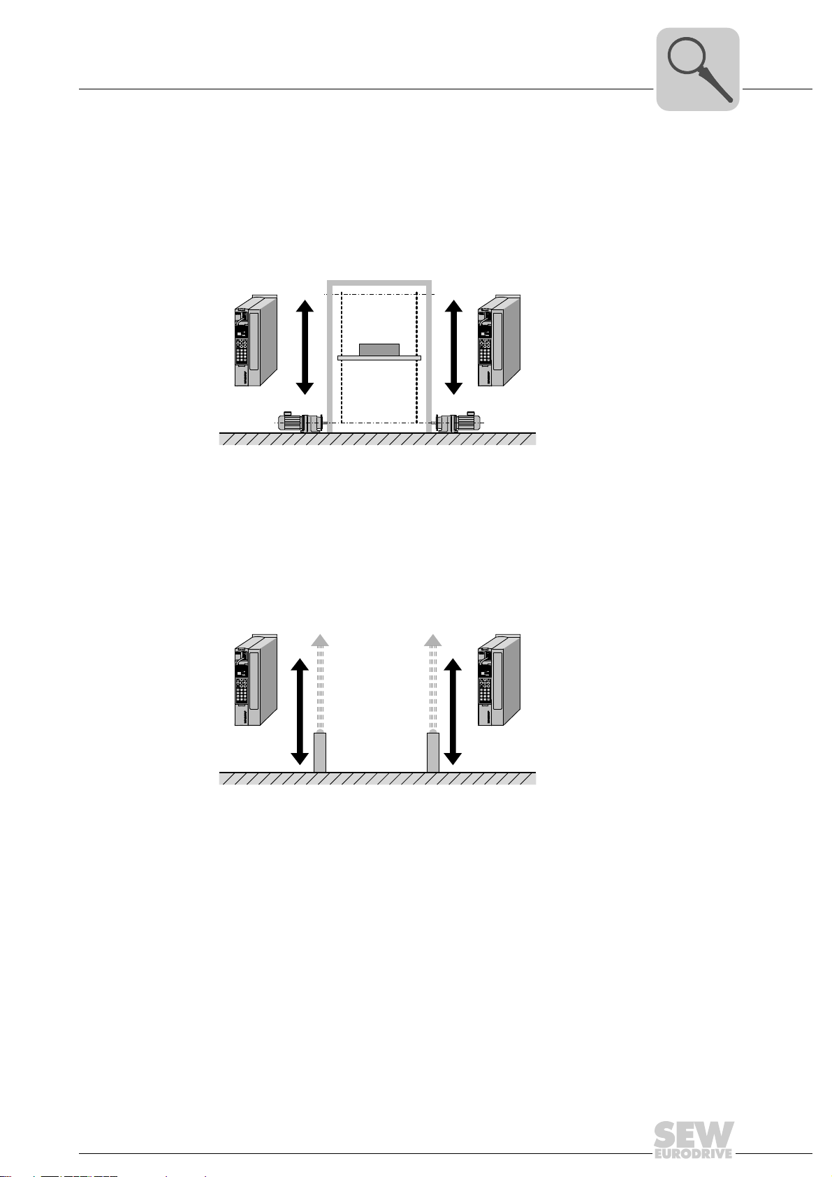
3.2.1 Finite (linear) movement of the master and slave axis
Example 1: Hoist
System Description
Application examples
3
Master
• Master axis: Linear axis
Operating mode: Positioning mode
• Slave axis: Linear axis
Operating mode: Synchronous operation
Example 2: Gantry crane with slip compensation through absolute encoder evaluation
Master
Slave
3031192715
Slave
• Master axis: Linear axis
Operating mode: Positioning mode using additional absolute encoder (IPOS encoder)
• Slave axis: Linear axis
Operating mode: Synchronous operation using an additional absolute encoder
• Master value: Master position (absolute value encoder position) is transferred via
SBus
• Features: Slip between motor and absolute encoder is compensated by the firmware.
Additional performance is achieved by controlling the master and slave axis using the
virtual encoder. Both drives are controlled in "Synchronous operation" mode for this
purpose. The master drive is started with the master value "virtual encoder" and
transfers the setpoint position to the slave drive via SBus.
Manual – MOVIDRIVE® MDX61B "DriveSync via Fieldbus" Application
3031194635
11
3
Slave
Master
[1]
[2]
System Description
Application examples
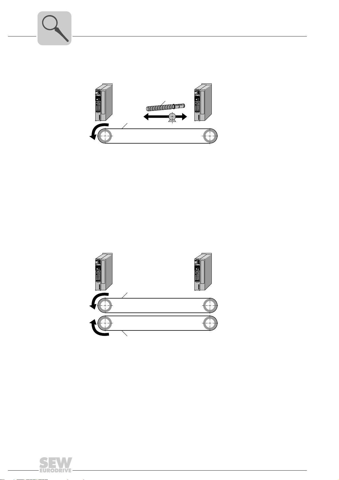
3.2.2 Finite (linear) movement of the slave axis and infinite movement of the master axis
Example 3: Belt drive with embossing punch (flying saw)
Master
[2]
[1]
• Master axis: Belt drive [1]
Operating mode: Speed specification, i.e. jog mode
• Slave axis: Spindle drive [2]
Operating mode: Synchronous operation forward; Start cycle via interrupt event.
Once a certain actual position has been reached, the operating mode changes to
"Positioning mode".
• Features: Interrupt-controlled engaging
3.2.3 Finite movements with master and slave axes
Example 4: Caterpillar drive with position reference (360°)
Slave
3031391755
12
3031395851
• Master axis: Belt drive [1]
Operating mode: Positioning mode with position specified in modulo format
• Slave axis: Belt drive [2]
Operating mode: Synchronous operation with feedback in modulo format
• Features: Retained position reference due to modulo function with infinite division
factors of the gear ratio (i gear unit).
Manual – MOVIDRIVE® MDX61B "DriveSync via Fieldbus" Application
System Description
[A] [A]
Slave 1 Slave n
Master
[1] [2] [2]
Application examples
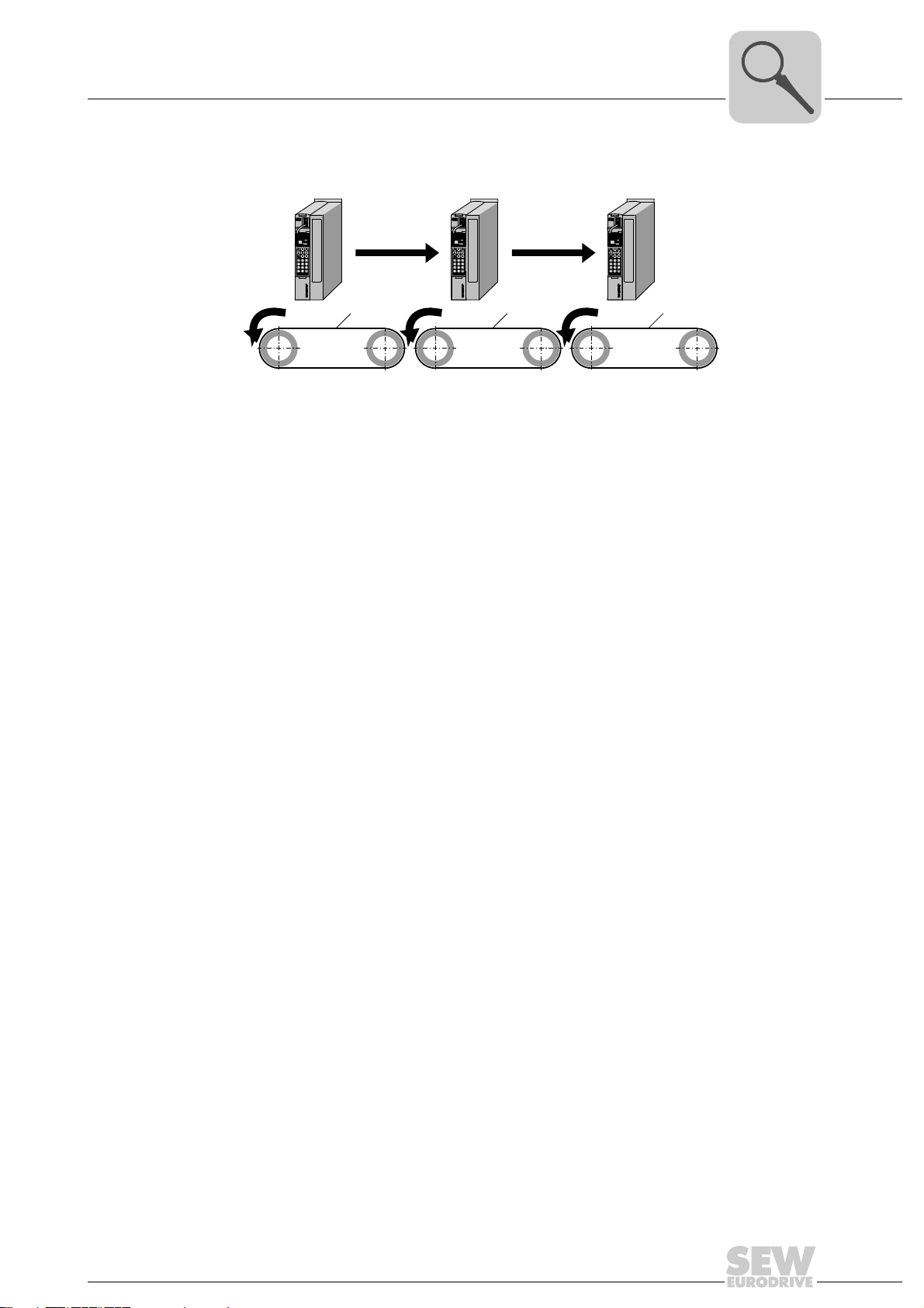
Example 5: Electronic replacement of the mechanical vertical shaft.
3031399179
• Master axis: Belt drive [1]
Operating mode: Synchronous operation with master value transfer to the subsequent slaves via SBus object.
• Slave axis: Belt drive [2]
Operating mode: Synchronous operation
Fluctuating actual speeds of the master drive are not transferred to the subsequent
slave drives because the virtual master encoder position is transferred.
3
Manual – MOVIDRIVE® MDX61B "DriveSync via Fieldbus" Application
13
3
System Description
Program identification
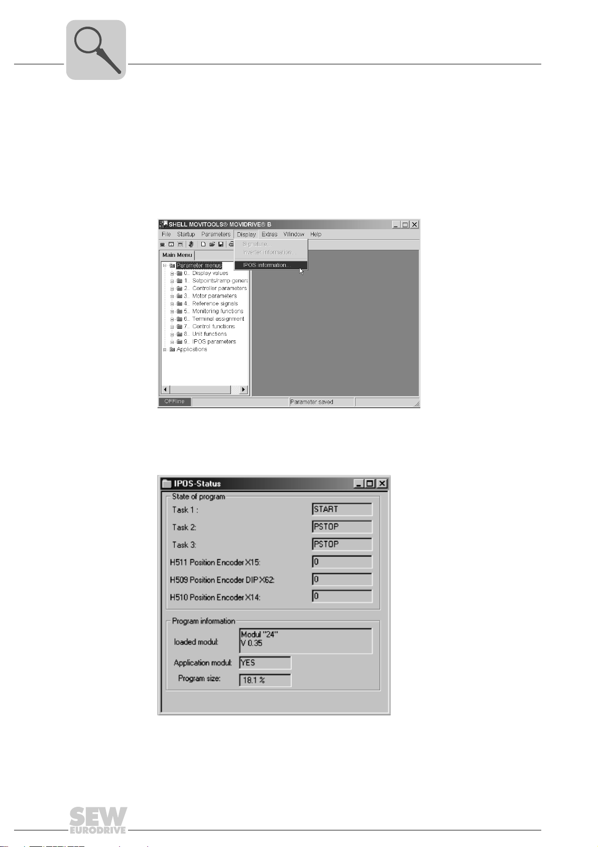
3.3 Program identification
You can use the MOVITOOLS® software package to identify which application program
was last loaded into the MOVIDRIVE
• Connect MOVIDRIVE
• Start MOVITOOLS
• In MOVITOOLS
• In the Shell program, choose [Display] / [IPOS Information...].
®
to the PC via the serial port.
®
.
®
, start the program "Shell".
®
MDX61B unit. Proceed as follows:
3032097291
• The "IPOS status" window appears. The entries in this window tell you which application software is stored in MOVIDRIVE
®
MDX61B.
3032102155
14
Manual – MOVIDRIVE® MDX61B "DriveSync via Fieldbus" Application

4 Project Planning
4.1 Prerequisites
4.1.1 PC and software
The "DriveSync via fieldbus" application module is implemented as an IPOS
gram and forms part of the SEW MOVITOOLS
order to use MOVITOOLS
tems: Windows
Windows
®
4.1.2 Inverters, motors and encoders
• Inverter
The application module is controlled via fieldbus with 6 process data words and can
only be implemented with MOVIDRIVE
• Motors and encoders
All motors with a connected motor encoder are supported.
®
2000.
Project Planning
Prerequisites
plus®
®
®
, you must have a PC with one of the following operating sys-
software package from version 4.30. In
95, Windows® 98, Windows® NT 4.0, Windows® XP, or
®
MDX61B units in application version (...0T).
pro-
4
4.1.3 Possible combinations
•MOVIDRIVE
Encoder type (external encoder)
Bus type
(required option)
Additional
MOVIDRIVE
required
4.1.4 Additional notes
• The source of the actual position is the motor encoder. In systems subject to slip, an
external encoder can additionally be fitted or an absolute encoder can be used in
combination with the "DIP11B absolute encoder card" option.
• If operated with asynchronous motors, the drive inverter must be started up in the
"CFC & IPOS" operating mode.
• If operated with synchronous servomotors, the drive inverter must be started up in
the "SERVO & IPOS" operating mode.
• In the "VFC n-control & IPOS" operating mode, the master and slave drives must not
be connected via SBus.
®
MDX61B with the following fieldbus interfaces
Connection of motor shaft and load
®
option
Interlocking:
External encoder is not
required
- Incremental
PROFIBUS (DFP) / INTERBUS (DFI) / CAN bus (DFC) / DeviceNet (DFD) /
Ethernet (DFE) / system bus (SBus) no option required
DEH11B or DER11B DIP11B / DEH11B /
Non-positive:
External encoder required
encoder
Absolute encoder
DER11B
Manual – MOVIDRIVE® MDX61B "DriveSync via Fieldbus" Application
15

4
Project Planning
Functional description
4.2 Functional description
4.2.1 Functional characteristics
The "DriveSync via fieldbus" application offers the following functional characteristics:
• Jog mode
• Referencing mode
• Positioning mode
The drive is moved clockwise or counterclockwise using two bits for direction selection. The speed and the ramp can be varied via fieldbus.
Reference travel is started with the start signal. Reference travel establishes the reference point (machine zero) for absolute positioning operations. The axis must be
referenced for selecting "positioning mode".
The machine control specifies the target position via process output data words PO2
and PO3. The speed and the ramp can be varied using the fieldbus. The current actual position is reported back via process input data words PI2 and PI3.
The program cyclically queries the target position so that position changes are possible during positioning. Positioning is only performed when the axis has been referenced.
• Synchronous operation
"Synchronous mode" is motion control based on the technology function "Internal
synchronous operation" (ISYNC).
After "synchronous operation" has been selected, the engaging process is started by
a engaging event that is defined during the startup procedure. Once the slave drive
has been synchronized with the master, the slave moves synchronously with the
master.
Synchronous operation is exited by resetting the “start bit” or deselecting "synchronous operation".
"Synchronous operation" can be started without prior reference travel.
In addition, a bus offset value (PO6) can be specified in synchronous mode to shift
the reference to the master axis without having to exit the operating mode.
16
Manual – MOVIDRIVE® MDX61B "DriveSync via Fieldbus" Application

4.2.2 Additional startup functions
You can choose the following additional functions at startup:
• Encoder in positioning mode (IPOS encoder source)
– Positive connection:
The incremental encoder, sin/cos encoder, or Hiperface
nected to terminal X15 of the DEH11B / DER11B option.
– Non-positive connection:
An encoder for slip compensation can be connected to terminal X14 of the
DEH11B / DER11B option in addition to the motor encoder. Alternatively, slip can
be compensated via the evaluation of an SSI absolute encoder (requires absolute
encoder card DIP11B option).
• Selecting the master drive source in "synchronous operation"
– Incremental encoder input X14 of the DEH11B / DER11B option for reading in the
master encoder value (is not allowed to be used if the input is already being used
as an IPOS encoder source).
– Simulation with the virtual master encoder. Variable specification of the position,
speed as well as acceleration via process output data words PO2 to PO5.
– Received "SBus data object" with read-in master encoder actual value of the mas-
ter drive. For example, each application module can operate as master and transfer the specified IPOS encoder source via SBus.
Project Planning
Functional description
®
encoder can be con-
4
• Control via fieldbus
– Fieldbuses with communication via 6 process data words (PROFIBUS, INTER-
BUS, DeviceNet, CANopen, Ethernet, SBus 2) are supported.
• Special function "positioning in modulo format" for endless movements
– Positioning can be in modulo format for endless movements (e.g. conveyor belts).
As a result, it is possible to achieve endless movements without losing the position reference to the reference position.
– The modulo travel range is limited to 0 ... < 360°
– The modulo travel strategy can be changed as follows in positioning mode:
Jog + = FALSE and Jog – = FALSE
The setpoint position is always reached on the "shortest route".
Jog+ = TRUE and Jog– = FALSE
The setpoint position is always reached by traveling "clockwise".
Jog+ = FALSE and Jog– = TRUE
The setpoint position is always reached by traveling "counterclockwise".
Manual – MOVIDRIVE® MDX61B "DriveSync via Fieldbus" Application
17

4
Project Planning
Scaling of the drive
4.3 Scaling of the drive
The controller must be able to detect the number of encoder pulses (increments) per
travel unit to position the drive. The scaling function is used to set a user unit suitable to
the application.
4.3.1 Drive without external encoder (positive connection)
In drives without an external encoder, the system can calculate the scaling automatically
during startup of the application module. Enter the following data:
• Diameter of the drive wheel (d
• Gear ratio of the gear unit (i
• Gear ratio of the additional gear (i
The following scaling factors are calculated:
• Pulses / distance scaling factor [inc/mm] using the formula:
Pulses = 4096 × i
Distance = π × d
gear unit
drive wheel
• Speed scaling factor
Numerator factor in [rpm] and denominator value in "speed units".
× i
drive wheel
gear unit
additional gear
additional gear
or π × s
) or slope of the spindle (s
speed-reduction)
speed-reduction)
spindle
spindle
)
You can also enter the distance and velocity scaling factors directly. If you enter a unit
other than [mm] or [1/10 mm] for the travel unit, this user unit will also be used for the
position of the software limit switches, the reference offset and the maximum travel distances.
18
Manual – MOVIDRIVE® MDX61B "DriveSync via Fieldbus" Application
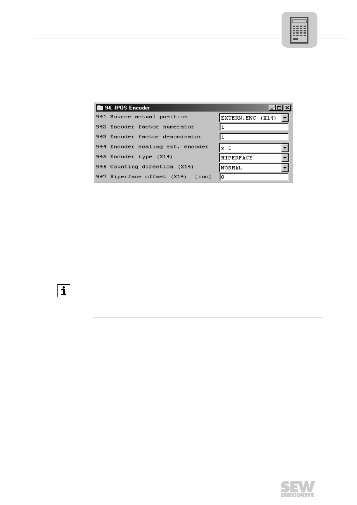
4.3.2 Drive with external encoder (non-positive connection)
In this case, you must have activated and scaled the external encoder before starting
up the "DriveSync via fieldbus" application module. To do so, make the following set-
tings in the Shell program before starting up the "DriveSync via fieldbus" application
module.
• P941 Source actual position
Project Planning
Scaling of the drive
4
3032773387
If an incremental encoder or an absolute encoder (DIP11) is connected, set P941 to
"EXT. ENCODER (X14)". You can also make this setting during the startup procedure of the application module.
• P942 Encoder factor numerator / P943 Encoder factor denominator / P944 Encoder
scaling ext. Encoder
Calculation of the scaling is blocked during startup of the application module.
INFORMATION
• For more information about scaling an external encoder, refer to the "IPOS
Positioning and Sequence Control System" manual.
• When using an absolute encoder, note the startup instructions in the
"MOVIDRIVE
®
MDX61B Absolute Encoder Card DIP11B" manual.
plus®
Manual – MOVIDRIVE® MDX61B "DriveSync via Fieldbus" Application
19

4
Project Planning
Limit switches, reference cams and machine zero
4.4 Limit switches, reference cams and machine zero
Note the following points during project planning:
• The software limit switches must be located within the travel range of the hardware
limit switches.
• When defining the reference position (position of the reference cam) and the software limit switches, make sure they do not overlap. Error message F78 "IPOS SW
limit switch" is generated in the event of an overlap during referencing.
• You can enter a reference offset during startup if you do not want the machine zero
to be located on the reference cam. The following formula applies: Machine zero =
reference position + reference offset. This way, you can alter the machine zero without having to move the reference cam.
INFORMATION
Please also refer to the information in chapter "Software limit switches".
20
Manual – MOVIDRIVE® MDX61B "DriveSync via Fieldbus" Application

4.5 Process data assignment
PI
PO
PO1
PI1
PO2
PI2
PO3 PO4 PO5 PO6
PI3 PI4 PI5 PI6
The machine control (PLC) sends 6 process output data words (PO1 – PO6) to the inverter and receives 6 process input data words (PI1 – PI6) from the inverter.
PO= Process output data
PO1 = Control word 2
PO2 = Target position high
PO3 = Target position low
PO4 = Setpoint speed (IPOS PO data)
PO5 = Acceleration and deceleration ramp (IPOS PO data)
PO6 = Offset (IPOS PO data)
PI= Process input data
PI1 = Status word (IPOS PI data)
PI2 = Actual pos. high (IPOS PI data)
PI3 = Actual pos. low (IPOS PI data)
PI4 = Actual speed (IPOS PO data)
PI5 = Master/slave position difference (IPOS PI data)
PI6 = Active current (IPOS PI data)
Project Planning
Process data assignment
4
3044175371
Manual – MOVIDRIVE® MDX61B "DriveSync via Fieldbus" Application
21
4
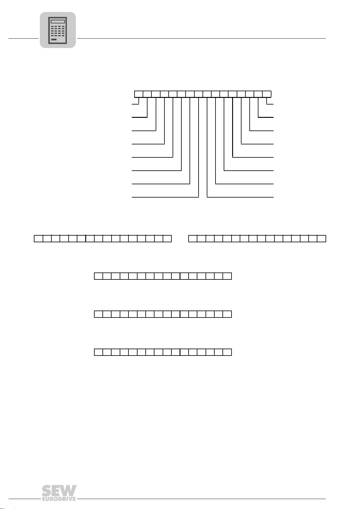
4.5.1 Process output data
Project Planning
Process data assignment
The process output data words are assigned as follows:
• PO1: Control word 2
1514131211109876543210
/SW LS off
Offset Enable/rapid stop
Set zero point Enable/stop
Mode high /Hold control
Mode low Ramp switchover
Controller inhibit/
enable
Jog –
Jog + Error reset
Start Reserved
Parameter set
switchover
• PO2 + PO3: Target position
PO2 Target position high PO3 Target position low
31 30 29 28 27 26 25 24 23 22 21 20 19 18 17 16 15 14 13 12 11 10 9 8 7 6 5 4 3 2 1 0
Target position [user unit]
• PO4: Setpoint speed
15 14 13 12 11 10 9 8 7 6 5 4 3 2 1 0
Setpoint speed [user unit]
• PO5: Ramp up and down
15 14 13 12 11 10 9 8 7 6 5 4 3 2 1 0
Ramp up and down [ms]
• PO6: Offset
15 14 13 12 11 10 9 8 7 6 5 4 3 2 1 0
Bus offset [user-defined units]
22
Manual – MOVIDRIVE® MDX61B "DriveSync via Fieldbus" Application
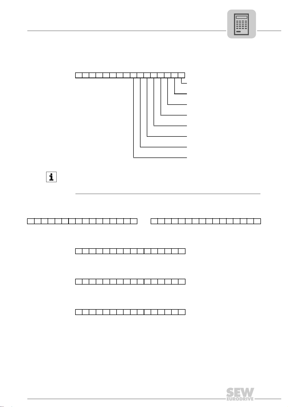
4.5.2 Process input data
The process input data words are assigned as follows:
• PI1: Status word
1514131211109876543210
Inverter status/error code
Project Planning
Process data assignment
Drive synchronous
Inverter ready
IPOS reference (= drive referenced)
Target position reached
Brake released
Error/warning
Limit switch right
Limit switch left
4
INFORMATION
The fault code is displayed in the high byte (bits 8 to 15) of the status word if bit 5
"Fault/warning" is set. If there is no fault, the current unit status is displayed in the high
byte of the status word.
• PI2 + PI3: Actual position
PI2 Actual position high PI3 Actual position low
31 30 29 28 27 26 25 24 23 22 21 20 19 18 17 16 15 14 13 12 11 10 9 8 7 6 5 4 3 2 1 0
• PI4: Actual speed
15 14 13 12 11 10 9 8 7 6 5 4 3 2 1 0
Velocity [user units]
• PI5: Master/slave position difference
15 14 13 12 11 10 9 8 7 6 5 4 3 2 1 0
Lag distance [user units]
• PI6: Active current
15 14 13 12 11 10 9 8 7 6 5 4 3 2 1 0
Active current [% I
]
N
Manual – MOVIDRIVE® MDX61B "DriveSync via Fieldbus" Application
23
4
SWLS CCW
SWLS CW
Motor position
Project Planning
Software limit switches
4.6 Software limit switches
4.6.1 General information
The "software limit switch" monitoring function is used to ensure that the target position
is set to appropriate values. During this process, it is not important where the drive is
positioned. Unlike the monitoring of the hardware limit switches, the monitoring function
for the software limit switches makes it possible to detect whether there is an error in the
target specifications before the axis starts to move. The software limit switches are active when the axis is referenced; that is, when the bit "IPOS reference" is set in PI1.
INFORMATION
The "software limit switch" monitoring function is disabled in synchronous mode.
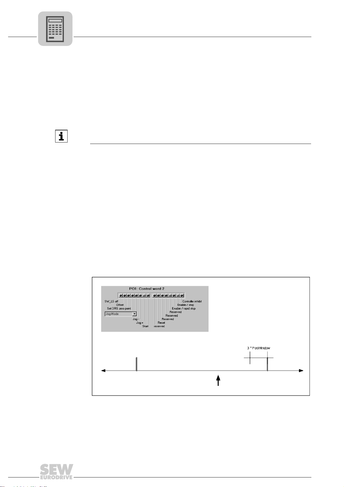
4.6.2 Moving clear of the software limit switches
When using an absolute encoder or multi-turn Hiperface
for the drive to be moved within the range of the software limit switches (for example,
after an encoder has been replaced). For this purpose, Bit 15 in the process output data
word 1 (PO1) is set to "/SWLS" (= Moving clear of the software limit switches).
®
encoder it may be necessary
Bit 15 "/SWLS" is only available in "jog mode" and "referencing mode". If bit 15 is set,
the drive can be moved out of the valid positioning range into the area of the software
limit switches (→ example 3).
Case no. 1 It is necessary to differentiate between the following three examples:
• Requirements:
– Bit 15 "/SWLS" in the process output data word 1 (PO1) is not set.
– Drive is within valid positioning area.
– Software limit switch monitoring function is active.
24
3044199819
In jog mode, the drive runs until it is three position windows (P922) before the software limit switch and then stays there.
In positioning mode, the drive can be positioned up to the software limit switches
but not beyond.
Manual – MOVIDRIVE® MDX61B "DriveSync via Fieldbus" Application
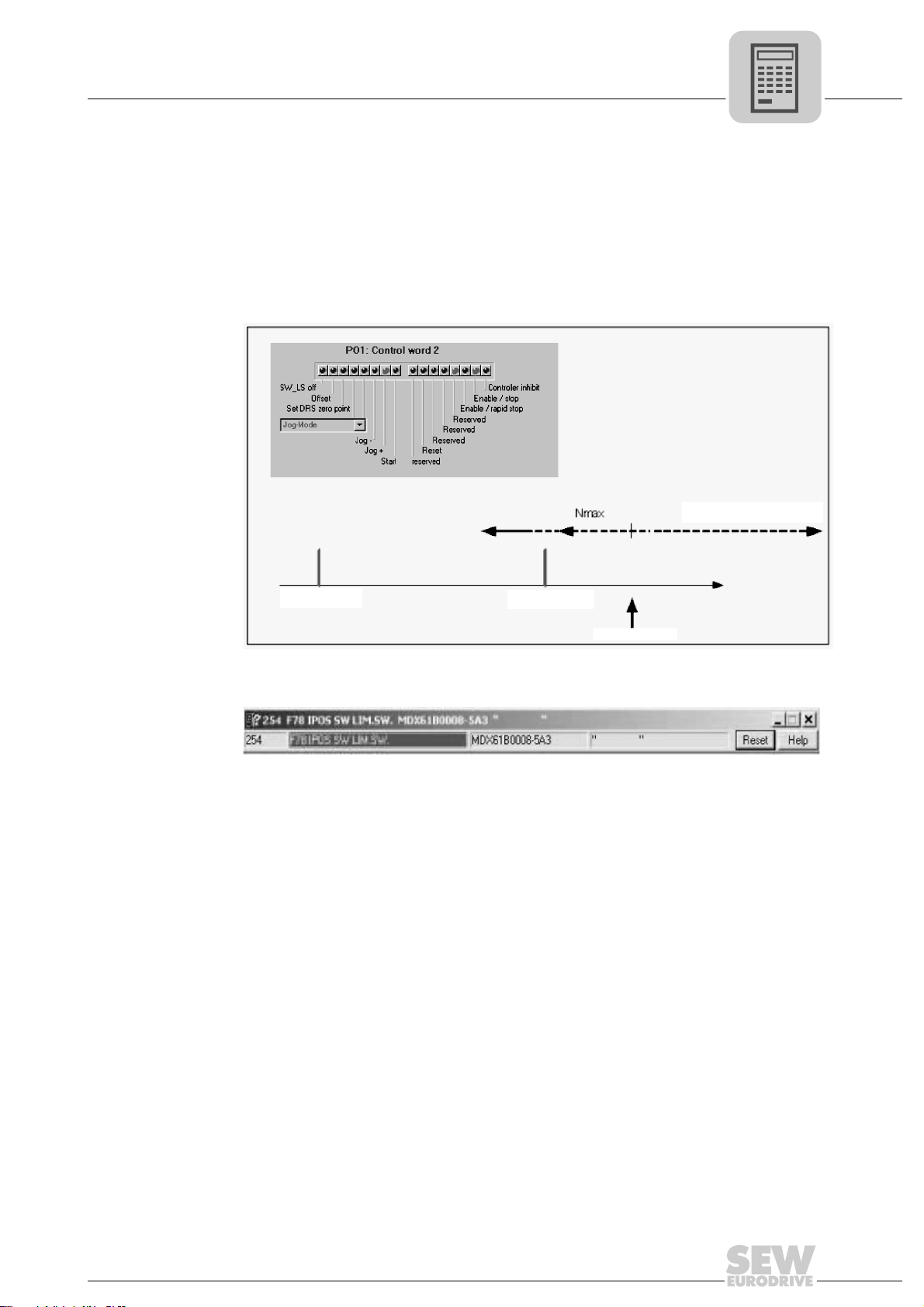
In referencing mode, the software limit switches are not active, which means the
SWLS CCW
SWLS CW
Motor position
Reference speed 2 (P902)
drive can move past the software limit switches during reference travel.
Case no. 2 • Requirements:
– Bit 15 "/SWLS" in the process output data word 1 (PO1) is not set.
– The drive is outside the software limit switches.
Project Planning
Software limit switches
4
3044204811
The following error message appears once the drive is enabled:
3044227851
Click <Reset> to acknowledge the error message. The monitoring function is deactivated. For example, if the drive is right to the software limit switch (see above figure), the drive can be moved at two different velocities depending on the specified
direction of the motor rotation:
– Closer toward the travel range of the software limit switch at reference speed 2
(P902).
– Away from the travel range of the software limit switches at maximum speed.
The monitoring function is reactivated when:
– The actual position of the drive set using P941 enters the permitted positioning
range again.
– A positioning job is issued via the opposite software limit switch.
– The unit is switched off and on again.
Manual – MOVIDRIVE® MDX61B "DriveSync via Fieldbus" Application
25

4
SWLS CCW
SWLS CW
Case no. 3 • Requirement:
Project Planning
Safe stop
– Bit 15 "/SWLS" in the process output data word 1 (PO1) is set.
4.7 Safe stop
3044210443
The monitoring function is deactivated in the modes "jog" and "referencing". The
drive can be moved within the travel area of the software limit switches and from the
valid positioning range into the area of the software limit switches without an error
message being generated. The speed can be varied.
WARNING
Risk of crushing if the motor starts coasting.
Severe or fatal injuries.
• You must not change the monitoring function of the software limit switches (PO1,
Bit 15 "/SWLS") during operation (i.e. when the axis is in motion).
• Observe startup notes.
A "Safe stop" can only be achieved by safe disconnection of the jumpers at terminal X17
(with safety switch or safety PLC).
The "Safe stop active" state is indicated by a "U" in the 7-segment display. In the application module, this state is treated in the same way as the "CONTROLLER INHIBIT"
state.
26
INFORMATION
For more information on the Safe stop function, refer to the following publications:
• Safe disconnection for MOVIDRIVE
• Safe disconnection for MOVIDRIVE
Manual – MOVIDRIVE® MDX61B "DriveSync via Fieldbus" Application
®
MDX60B/61B - Conditions
®
MDX60B/61B - Applications
5 Installation
5.1 MOVITOOLS® software
5.1.1 MOVITOOLS
®
The "DriveSync via fieldbus" application module is part of the MOVITOOLS® software
(version 4.30 and higher). Proceed as follows to install MOVITOOLS
puter:
• Insert the MOVITOOLS
• The MOVITOOLS
process: Follow the instructions.
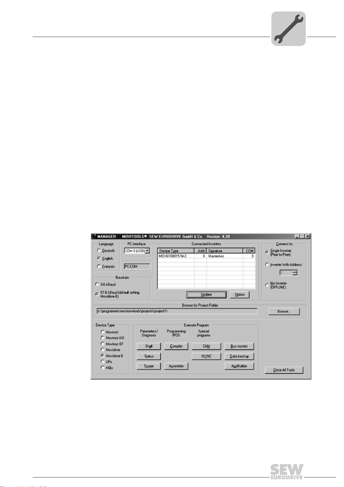
You can now use the Program Manager to start MOVITOOLS
perform startup for the inverter using the MOVITOOLS
• Select the language you want in the "Language" group.
• In the "PC COM" selection field, select the PC port (e.g. COM 1) to which the inverter
is connected.
Installation
MOVITOOLS® software
®
on your com-
®
CD into the CD-ROM drive of your PC.
®
setup menu is started. You will be guided through the installation
®
®
Manager:
. Proceed as follows to
5
• In the "Device type" group, select "MOVIDRIVE B".
• In the "Baud rate" field, select the baud rate set on the basic unit with the DIP switch
S13 (standard setting "57.6 kbaud").
• Click [Update] to display the connected inverter.
5.1.2 Application variant
The "DriveSync via fieldbus" application module can be used with the MOVIDRIVE
plication variant (-0T). The application modules cannot be used on units in the standard
version (-00).
Manual – MOVIDRIVE® MDX61B "DriveSync via Fieldbus" Application
3044477835
®
ap-
27
5
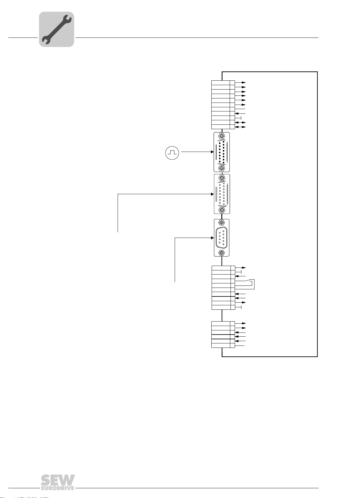
X13:
X14:
X15:
X15:
1
2
3
4
5
6
7
8
9
10
11
DEH11B / DER11B option
1
8
9
15
X10:
TF1
DGND
DBØØ
DOØ1-C
DOØ1-NO
DOØ1-NC
DOØ2
VO24
VI24
DGND
1
2
3
4
5
6
7
8
9
10
TF/TH input
Reference potential for binary signals
/Brake
Relay contact/Ready *
Relay N/O contact
Relay N/C contact
/Fault *
DC+24V output
DC+24V input
Reference potential for binary signals
DIØØ
DIØ1
DIØ2
DIØ3
DIØ4
DIØ5
DCOM
VO24
DGND
ST11
ST12
/Controller inhibit
No enable
IPOS input (material sensor)
Reference cam
/LS CW or no function
/LS CCW or no function
Reference
X13:DIØØ...DIØ
5
DC+24V output
Reference potential bianry signals
RS-485+
RS-485-
MOVIDRIVE® MDX61B slave
External encoder input
DEH11B option
DER11B option
Resolver
(Connection: Operating instr. MOVIDRIVE
®
)
15
1
8
9
1
5
6
9
DEH11B option (motor encoder):
high resolution sin/cos encoder,
Hiperface encoder or incremental encoder
(CT/CV or DT/DV/D motors)
DER11B option (motor encoder):
Resolver (DS/CM motors)
Motor encoder
(Connection: Operating instr. MOVIDRIVE
®
(Connection: Operating instr. MOVIDRIVE
®
)
®
DEH11B / DER11B option (master):
Incremental encoder TTL/RS-422
with DC 24 V supply, I
max
= 180 mA
* Factory setting
X16:
1
2
3
4
5
6
DIØ6
DIØ7
DOØ3
DOØ4
DOØ5
DGND
Drive synchronous
IPOS reference
IPOS in position
Reference potential for binary signals
No function
Fault reset
Installation
Wiring diagram for incremental encoder master / MDX61B slave
5.2 Wiring diagram for incremental encoder master / MDX61B slave
3044591755
28
Manual – MOVIDRIVE® MDX61B "DriveSync via Fieldbus" Application
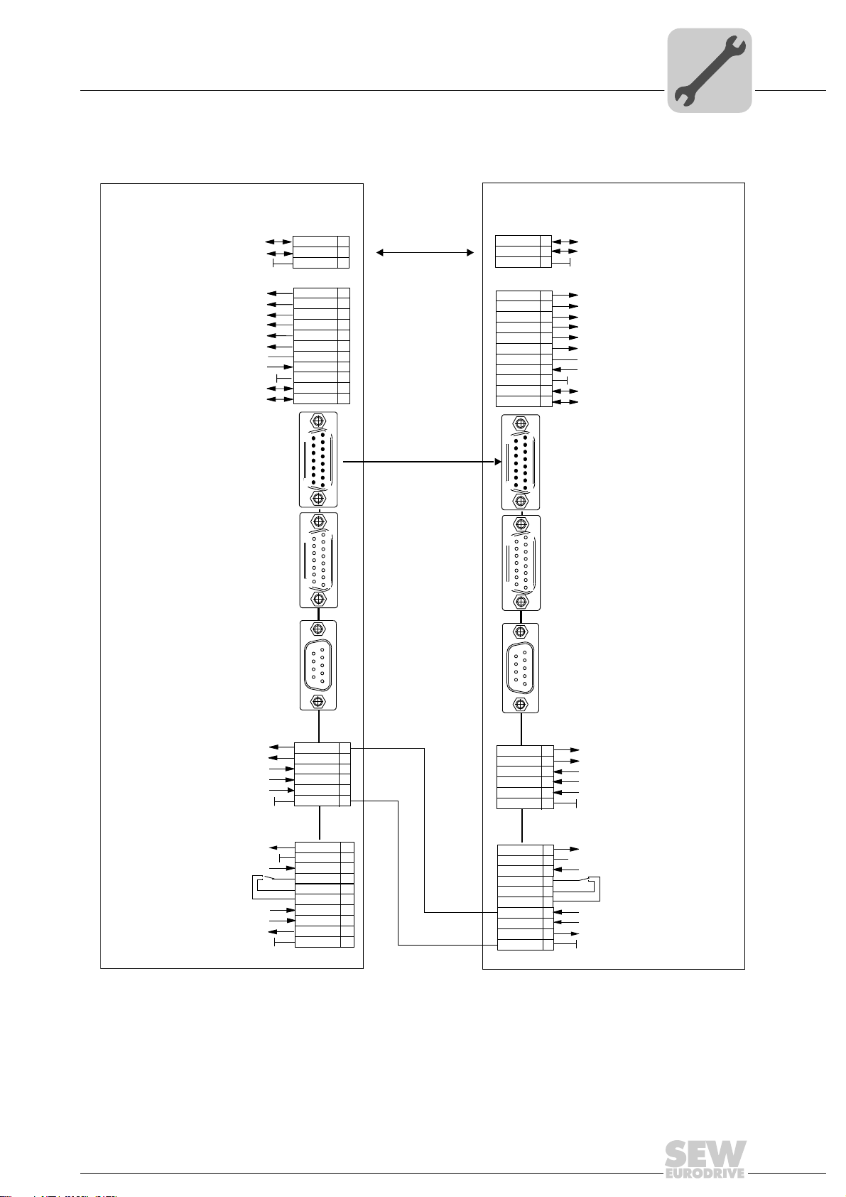
Wiring diagram for MDX61B master / MDX61B slave
5.3 Wiring diagram for MDX61B master / MDX61B slave
Installation
5
MOVIDRIVE MDX61B - Master
System bus reference
/Controller inhibit
IPOS input (material sensor)
Reference X13:DIØØ...DIØ5
Reference potential for binary signals
Option DEH11B / DER11B
®
System bus high
System bus low
No enable
Reference cam
/LS CW
/LS CCW
DC+24V output
RS-485+
RS-485-
External encoder input
Option DEH11B
Motor encoder
X14:
X15:
DGND
SC11
SC12
DIØØ
DIØ1
DIØ2
DIØ3
DIØ4
DIØ5
DCOM
VO24
DGND
ST11
ST10
9
15
15
9
X12:
X13:
1
8
8
1
MOVIDRIVE MDX61B - Slave
®
X12:
DGND
1
2
3
1
2
3
4
5
6
7
8
9
10
11
[1]
[2]
S
c
1
S
c1
DIØØ
DIØ1
DIØ2
DIØ3
DIØ4
DIØ5
DCOM
VO24
DGND
ST11
ST12
9
15
15
9
1
System bus reference
2
1
2
3
System bus high
System bus low
X13:
/Controller inhibit
1
No enable
2
IPOS input (material senor)
3
Reference cam
4
/LS C W
5
/LS CCW
6
Reference X13:DIØØ...DIØ5
7
8
DC+24V output
9
Reference potential for binary signals
10
RS-485+
11
RS-485-
X14:
1
Option DEH11B / DER11B
External encoder input
8
X15:
8
Option DEH11B
Motor encoder
(Connection: MOVIDRIVE
1
®
operating instructions)
Option DER11B
/Ext. error
Error reset
(drive synchronous)
IPOS reference
Reference potential for binary signals
Reference potential for binary signals
Relay contact/ready f. operation*
Reference potential for binary signals
IPOS in position
TF/TH input
NO contact relay
NC contact relay
DC+24V output
DC+24V input
/Brake
/Fault*
X15:
Resolver
5
9
6
1
DIØ6
DIØ7
DOØ3
DOØ4
DOØ5
DGND
TF1
DGND
DBØØ
DOØ1-C
DOØ1-NO
DOØ1-NC
DOØ2
VO24
VI24
DGND
X16:
X10:
[3a]
[3b]
DIØ6
DIØ7
DOØ3
DOØ4
DOØ5
DGND
DOØ1-NO
DOØ1-NC
1
2
3
4
5
6
1
2
3
4
5
6
7
8
9
10
X15:
Option DER11B
5
9
Resolver
6
1
(Connection: MOVIDRIVE
X16:
1
2
3
4
5
6
X10:
1
TF1
2
DGND
3
DBØØ
4
DOØ1-C
5
6
7
DOØ2
8
VO24
9
VI24
10
DGND
®
operating instructions)
No function
Error reset
Drive synchronous
IPOS reference
IPOS in position
Reference potential for binary signals
TF/TH input
Reference potential for binary signals
/Brake
Relay contact/ready f. operation*
NO contact relay
NC contact relay
/Fault*
DC+24V output
DC+24V input
Reference potential for binary signals
1359027979
[1] Synchronous mode master value is transferred via SBus connection (e.g. with a number of slaves > 1)
[2] Synchronous mode master value is transferred via DEH11B / DER11B option, X14
[3a, 3b] Wiring when using the "Immediate switch-off of the master drive in case of slave faults via (/ext. fault)"
function
Manual – MOVIDRIVE® MDX61B "DriveSync via Fieldbus" Application
29
 Loading...