

SEW movidrive MDX60B,movidrive MDX61B User Manual
Drive Technology \ Drive Automation \ System Integration \ Services
MOVIDRIVE
®
MDX60B/61B
Communication and Fieldbus Unit Profile
Edition 04/2009
11264926 / EN
Manual

SEW-EURODRIVE – Driving the world

1 General Information ............................................................................................... 6
1.1 How to use the documentation ...................................................................... 6
1.2 Structure of the safety notes .......................................................................... 6
1.3 Rights to claim under limited warranty ........................................................... 7
1.4 Exclusion of liability ........................................................................................ 7
1.5 Copyright........................................................................................................ 7
2 Safety Notes ........................................................................................................... 8
2.1 Other applicable documentation .................................................................... 8
2.2 General notes on bus systems....................................................................... 8
2.3 Safety functions ............................................................................................. 8
2.4 Hoist applications ........................................................................................... 8
2.5 Waste disposal............................................................................................... 8
3 Introduction ............................................................................................................ 9
3.1 Content of the manual.................................................................................... 9
3.2 Additional documentation............................................................................... 9
3.3 Communication interfaces of MOVIDRIVE
®
B............................................. 10
3.3.1 Overview of communication interfaces ............................................. 11
4 Serial Interfaces of MOVIDRIVE
®
B .................................................................... 12
4.1 Connecting and installing RS485 interfaces ................................................ 12
4.1.1 Connection using socket XT ............................................................. 12
4.1.2 Connection using terminals X13:10 and X13:11 ............................... 15
4.1.3 Shielding and routing cables ............................................................. 16
4.2 Configuration parameters of the serial interfaces ........................................ 17
4.3 MOVILINK
®
protocol via RS485 transmission method ................................ 18
4.3.1 Transmission method ........................................................................ 18
4.3.2 Telegrams ......................................................................................... 21
4.3.3 Addressing and transmission method ............................................... 23
4.3.4 Structure and length of user data ..................................................... 26
4.4 Other unit functions via RS485 interfaces.................................................... 29
4.4.1 Using RS485 interfaces for master/slave operation .......................... 29
4.4.2 Using the RS485 interfaces in IPOS
plus®
......................................... 33
4.4.3 Using RS485 interfaces for manual operation .................................. 33
5 CAN Interfaces of MOVIDRIVE
®
B ...................................................................... 34
5.1 Connecting and installing CAN .................................................................... 34
5.1.1 Connecting the two CAN interfaces CAN 1 and CAN 2 .................... 34
5.1.2 Shielding and routing cables ............................................................. 36
5.2 Configuration parameters of the CAN interfaces ......................................... 38
5.3 MOVILINK
5.3.1 Telegrams ......................................................................................... 39
5.3.2 Parameter setting via CAN (SBus MOVILINK
®
profile via CAN......................................................................... 39
®
) ............................... 44
5.4 CANopen profile via CAN............................................................................. 45
5.4.1 Configuring the CANopen interface of MDX B and
network management (NMT) ............................................................ 46
5.4.2 Process data exchange .................................................................... 48
5.4.3 SYNC object ..................................................................................... 52
5.4.4 The emergency object ...................................................................... 53
5.4.5 Heartbeat and lifetime ....................................................................... 54
5.4.6 Parameter access via SDO ............................................................... 55
5.4.7 Hard synchronization for synchronous operation
or positioning several MDX-B units ................................................... 56
5.4.8 Other unit properties in the CANopen profile .................................... 57
5.4.9 CANopen-specific objects of MOVIDRIVE
®
B .................................. 57
Manual – MOVIDRIVE® MDX60B/61B Communication and Fieldbus Unit Profile
3

5.5 Other unit functions via CAN interfaces ....................................................... 60
5.5.1 Using CAN interfaces for master/slave operation ............................. 60
5.5.2 Using CAN interfaces in IPOS
5.5.3 Using CAN interfaces in IPOS
plus®
(depending on the profile) ......... 61
plus®
(independent of the profile) ....... 62
5.5.4 Using CAN interfaces for integrated synchronous
operation (ISYNC via SBus) ............................................................. 63
6 Fieldbus Interfaces via Option Card for MOVIDRIVE
6.1 Installing a fieldbus option card in MOVIDRIVE
®
B.................................. 67
®
MDX61B ......................... 68
6.1.1 Before you start ................................................................................ 69
6.1.2 Basic procedure for installing/removing an option card
(MDX61B, sizes 1 - 6) ....................................................................... 70
6.2 Parameters for configuring communication via fieldbus option.................... 71
6.3 Process and parameter access via fieldbus................................................. 73
6.4 Other unit functions via fieldbus option card ................................................ 73
6.4.1 Using the fieldbus options in IPOS
plus®
............................................ 73
6.4.2 Engineering via fieldbus .................................................................... 73
6.4.3 Engineering via fieldbus and controller ............................................ 73
6.4.4 Diagnostics via WEB server .............................................................. 74
6.4.5 Motion control ................................................................................... 74
7 SEW Unit Profile................................................................................................... 75
7.1 Process data ................................................................................................ 76
7.2 Process data configuration .......................................................................... 78
7.3 Process data description.............................................................................. 79
7.4 Sequence control ......................................................................................... 87
7.4.1 Definition of the control word ............................................................ 87
7.4.2 Linking safety-relevant control commands ....................................... 88
7.4.3 Control commands ............................................................................ 89
7.4.4 Control word 1 .................................................................................. 91
7.4.5 Control word 2 .................................................................................. 92
7.4.6 Status word definition ....................................................................... 93
7.4.7 Status word 1 .................................................................................... 94
7.4.8 Status word 2 .................................................................................... 95
7.4.9 Status word 3 .................................................................................... 96
7.4.10 Fault number and unit status ........................................................... 97
7.5 Monitoring functions ..................................................................................... 99
7.6 Setting the inverter parameters.................................................................. 101
7.6.1 Structure of the MOVILINK
®
parameter channel ............................ 102
7.6.2 Return codes of parameterization ................................................... 106
7.6.3 Example: Reading a parameter (READ) ......................................... 109
7.6.4 Example: Writing a parameter (WRITE) ......................................... 110
7.7 Notes on parameterization ......................................................................... 113
8 Operating MOVITOOLS
8.1 About MOVITOOLS
®
MotionStudio............................................................ 114
®
MotionStudio ........................................................... 114
8.1.1 Tasks .............................................................................................. 114
8.1.2 Establishing communication with the units ..................................... 114
8.1.3 Executing functions with the units ................................................... 114
8.2 First steps .................................................................................................. 115
8.2.1 Starting the software and creating a project ................................... 115
8.2.2 Establishing communication and scanning the network ................. 115
8.3 Communication mode ................................................................................ 116
8.3.1 Overview ......................................................................................... 116
8.3.2 Selecting communication mode (online or offline) .......................... 117
4
Manual – MOVIDRIVE® MDX60B/61B Communication and Fieldbus Unit Profile

8.4 Serial communication (RS485) via interface adapters ............................... 118
8.4.1 Engineering via interface adapters (serial) ..................................... 118
8.4.2 Taking the USB11A interface adapter into operation ...................... 118
8.4.3 Configuring serial communication ................................................... 121
8.4.4 Serial communication parameter (RS485) ...................................... 123
8.5 Communication SBus (CAN) via interface adapter .................................... 124
8.5.1 Engineering via interface adapters (SBus) ..................................... 124
8.5.2 Taking the USB-CAN interface into operation ................................ 124
8.5.3 Configuring communication via SBus ............................................. 126
8.5.4 Communication parameters for SBus ............................................. 128
8.6 Communication via Ethernet, fieldbus or SBUSplus .................................. 129
8.6.1 Connecting the unit with the PC via Ethernet ................................. 129
8.7 Executing functions with the units .............................................................. 129
8.7.1 Parameterizing units in the parameter tree ..................................... 129
8.7.2 Reading/changing unit parameters ................................................. 129
8.7.3 Starting up the units (online) ........................................................... 130
8.7.4 Unit-internal scope .......................................................................... 131
8.8 Bus monitor................................................................................................ 131
8.8.1 Diagnostic mode of the bus monitor .............................................. 131
8.8.2 Control using bus monitor ............................................................... 131
8.9 Manual operation ....................................................................................... 131
9 Bus Diagnostics ................................................................................................. 132
9.1 Checking the parameter setting ................................................................. 132
9.2 Diagnostics of process input and output data ............................................ 134
9.3 Diagnostic options for RS485 communication ........................................... 135
9.4 Diagnostic options for CAN communication............................................... 137
9.5 Diagnostic options for communication via fieldbus option card.................. 139
10 Index .................................................................................................................... 140
Manual – MOVIDRIVE® MDX60B/61B Communication and Fieldbus Unit Profile
5
1
General Information
How to use the documentation
1 General Information
Handbuch
1.1 How to use the documentation
The documentation is an integral part of the product and contain important information
on operation and service. The documentation is written for all employees who assemble,
install, startup, and service this product.
1.2 Structure of the safety notes
The safety notes in this documentation are structured as follows:
Pictogram SIGNAL WORD
Type and source of danger.
Possible consequence(s) if disregarded.
• Measure(s) to prevent the danger.
Pictogram Signal word Meaning Consequences if
disregarded
Example:
DANGER Imminent danger Severe or fatal injuries
General danger
Specific danger,
e.g. electric shock
WARNING Possible dangerous situation Severe or fatal injuries
CAUTION Possible dangerous situation Minor injuries
NOTICE Possible damage to property Damage to the drive system or its
environment
TIP Useful information or tip.
Simplifies the handling of the
drive system.
6
Manual – MOVIDRIVE® MDX60B/61B Communication and Fieldbus Unit Profile

Rights to claim under limited warranty
1.3 Rights to claim under limited warranty
A requirement of fault-free operation and fulfillment of any rights to claim under limited
warranty is that you adhere to the information in the documentation. Read the documentation before you start working with the unit!
Make sure that the documentation is available to persons responsible for the system and
its operation as well as to persons who work independently on the unit. You must also
ensure that the documentation is legible.
1.4 Exclusion of liability
You must observe this documentation and the documentation of the connected units
from SEW-EURODRIVE to ensure safe operation and to achieve the specified product
characteristics and performance requirements. SEW-EURODRIVE assumes no liability
for injury to persons or damage to equipment or property resulting from non-observance
of the operating instructions. In such cases, any liability for defects is excluded.
1.5 Copyright
General Information
1
© 2008 - SEW-EURODRIVE. All rights reserved.
Copyright law prohibits the unauthorized duplication, modification, distribution, and use
of this document, in whole or in part.
Manual – MOVIDRIVE® MDX60B/61B Communication and Fieldbus Unit Profile
7

2
Safety Notes
Other applicable documentation
2 Safety Notes
2.1 Other applicable documentation
Only electrical specialists are allowed to perform installation and startup observing
relevant accident prevention regulations and the MOVIDRIVE
instructions.
Read through these documents carefully before you commence installation and startup
of the communication interfaces of MOVIDRIVE
As a prerequisite to fault-free operation and fulfillment of warranty claims, you must
adhere to the information in the documentation.
2.2 General notes on bus systems
MOVIDRIVE® B has communication interfaces that make it possible to adapt the
MOVIDRIVE
bus systems, there is a danger of invisible, external (as far as the inverter is concerned)
modifications to the parameters which give rise to changes in the unit behavior. This
may result in unexpected (not uncontrolled) system behavior.
®
B inverter to the particulars of the machinery within wide limits. As with all
2.3 Safety functions
The MOVIDRIVE® MDX60B/61B inverters may not perform safety functions without
higher-level safety systems. Use higher-level safety systems to ensure protection of
equipment and personnel. For safety applications, ensure that the information in the
following publications is observed: "Safe Disconnection for MOVIDRIVE
MDX60B/61B".
®
MDX60B/61B operating
®
B.
®
2.4 Hoist applications
MOVIDRIVE® MDX60B/61B is not designed for use as a safety device in hoist applications.
Use monitoring systems or mechanical protection devices as safety equipment to avoid
possible damage to property or injury to people.
2.5 Waste disposal
Observe the applicable national regulations.
Dispose of the following materials separately in accordance with the country-specific
regulations in force, as:
• Electronics scrap
• Plastic
• Sheet metal
• Copper
8
Manual – MOVIDRIVE® MDX60B/61B Communication and Fieldbus Unit Profile

3 Introduction
3.1 Content of the manual
The manual describes the communication interfaces of the MOVIDRIVE® MDX60B/61B
inverter:
• 2 serial interfaces
• 2 CAN interfaces, one via DFC11B option card
• Fieldbus or Ethernet interface depending on the installed option card
The manual provides a description of the connection, configuration parameters, as well
as of the process and parameter data exchange via the communication interfaces of
MOVIDRIVE
The manual also describes how MOVITOOLS
MOVIDRIVE
controllers (PLC) can control MOVIDRIVE
3.2 Additional documentation
®
B.
®
B using the communication interfaces, and how programmable logic -
Introduction
Content of the manual
®
MotionStudio communicates with
®
B via the communication interfaces.
3
For simple connection of MOVIDRIVE® B to fieldbus systems, have the following
documents at hand in addition to the manual:
•MOVIDRIVE
•MOVIDRIVE
The MOVIDRIVE
device firmware and includes a list of all device indices and error codes. It supplements the system manual as the latter is not rewritten for every firmware version.
• The manual of the fieldbus option used (e.g. DFP21B)
The manuals on the fieldbus options and the manual at hand describe the access to
process and parameter data in general and do not include a detailed description of
all the possible control concepts.
®
MDX60/61B system manual
®
B list of parameters
®
B list of parameters describes the device parameters for every
Manual – MOVIDRIVE® MDX60B/61B Communication and Fieldbus Unit Profile
9
3
2
2
2
4
5
6
2
2
2
2
0
1
2
3
XT
S
S
3
0
2
2
2
4
5
6
2
2
2
2
0
1
2
3
nc
ADDRESS
X30
[1]
[2]
[3]
[4
DGND
SC1
1
SC12
1
2
3
System bus reference
System bus High
System bus Low
DIØØ
DIØ1
DIØ2
DIØ3
DIØ4
DIØ5
DCOM*
*
VO24
1
2
3
4
5
6
7
8
DGND
ST11
ST12
9
10
11
RS485 -
RS485 +
S
S
Ø
Ø
D
IØ1
Ø
D
I
Ø
3
Ø
D
I
Ø
5
DCOM
VO
2
3
4
5
6
7
DFP 21B
Introduction
Communication interfaces of MOVIDRIVE® B
3.3 Communication interfaces of MOVIDRIVE® B
12
13
14
X1
8
64323AEN
10
[1] Terminal XT
[2] Terminal X12:SBus 1 (CAN)
[3] Terminal X13:10 / X13:11 (RS485)
[4] Fieldbus port
Manual – MOVIDRIVE® MDX60B/61B Communication and Fieldbus Unit Profile

Introduction
Communication interfaces of MOVIDRIVE® B
[1] Terminal XT:
RS485 interface for point-to-point connection of a keypad (e.g. DBG60B or
DOP11B) or an interface adapter, such as USB11A or UWS21B for connection
to an engineering PC.
[2] X12: SBus 1 (CAN) for connection
• directly to controllers (CANopen or MOVILINK
• via an SEW fieldbus gateway to fieldbus systems, such as PROFIBUS,
DeviceNet, etc.
• to an engineering PC via PC via PC CAN interface or SEW fieldbus gateway
[3] Terminal X13:10 / X13:11
RS485 interface for networking up to 32 devices, for example for connecting
MOVIDRIVE
®
B to a DOP11B operator panel or for connection to an engeering
PC via interface adapter (e.g. UWS11A, COM server, or similar)
[4] Fieldbus port
• for installing the DFC11B option card for the SBus 2 (CAN) interface with the
same functionality as X12 (SBus1), or
• for installing a fieldbus option, for example PROFIBUS DFP21B, DeviceNet
DFD11B, etc. for direct connection to the relevant fieldbus system for
exchanging process and parameter data.
®
protocol)
3
3.3.1 Overview of communication interfaces
Serial interfaces CAN interfaces Fieldbus
Terminal / socket Socket XT [1] X13:10 / X13:11 [3] Terminal X12 [2] Fieldbus port [4]
Typ e RS485 CAN1 CAN2 or fieldbus option
Profile MOVILINK
Baud rate 9.6 / 57.6 kBaud
Electrical
isolation
Connector RJ10 Terminal Terminal
Bus termination Point-to-point Dynamic DIP switch S12 DIP switch R Depending on option card
Control/setpoint
source
P100/P101
Timeout
monitoring
Configuration of
the interface
(address, baud
rate, etc.)
Process data Configuration using P870 - P876
Master/slave No Yes Yes No No
Manual operation
(MOVITOOLS
plus®
IPOS
type
bus
®
)
(via S13)
No No No
Shared monitoring via P812, P833 Via P883 and P836 Via P893 and P837 Via P819 and P831
P810, P811 P88x P89x
12 5 8 3
®
9.6 kBaud 1000, 500, 250,
RS485 SBus 1 SBus 2 Fieldbus
Yes No
MOVILINK® or CANopen
125 kBaud
(with P884)
1000, 500, 250,
125 kBaud
(with P894)
Yes, on the
DFC11B option
Terminal and Sub
D9 (according to
CiA)
PROFIBUS DP, DeviceNet,
INTERBUS, etc.
Depending on option card
Yes
Depending on option card
Depending on the option
card via DIP switch or with
P78x
Manual – MOVIDRIVE® MDX60B/61B Communication and Fieldbus Unit Profile
11
4
[1]
[4]
Serial Interfaces of MOVIDRIVE® B
Connecting and installing RS485 interfaces
4 Serial Interfaces of MOVIDRIVE® B
As standard, MOVIDRIVE® B is equipped with two separate, serial RS485 interfaces:
•Socket XT
• Terminals X13:10 and X13:11
Telegrams received via a serial interface of MOVIDRIVE
other serial interface.
4.1 Connecting and installing RS485 interfaces
4.1.1 Connection using socket XT
The "XT socket" serial interface is designed as RJ10 plug connector (see following
figure).
Assignment of XT
connector (RJ10)
®
B are not passed on via the
Connection
options
64788AXX
[1] DC 5 V (from electronics supply)
[2] RS485 + (Rx/Tx)
[3] RS485 - (Rx/Tx)
[4] GND (electronics ground)
You can connect one of the following SEW options to the XT socket:
• DBG60B keypad
12
64252AXX
Manual – MOVIDRIVE® MDX60B/61B Communication and Fieldbus Unit Profile
Serial Interfaces of MOVIDRIVE® B
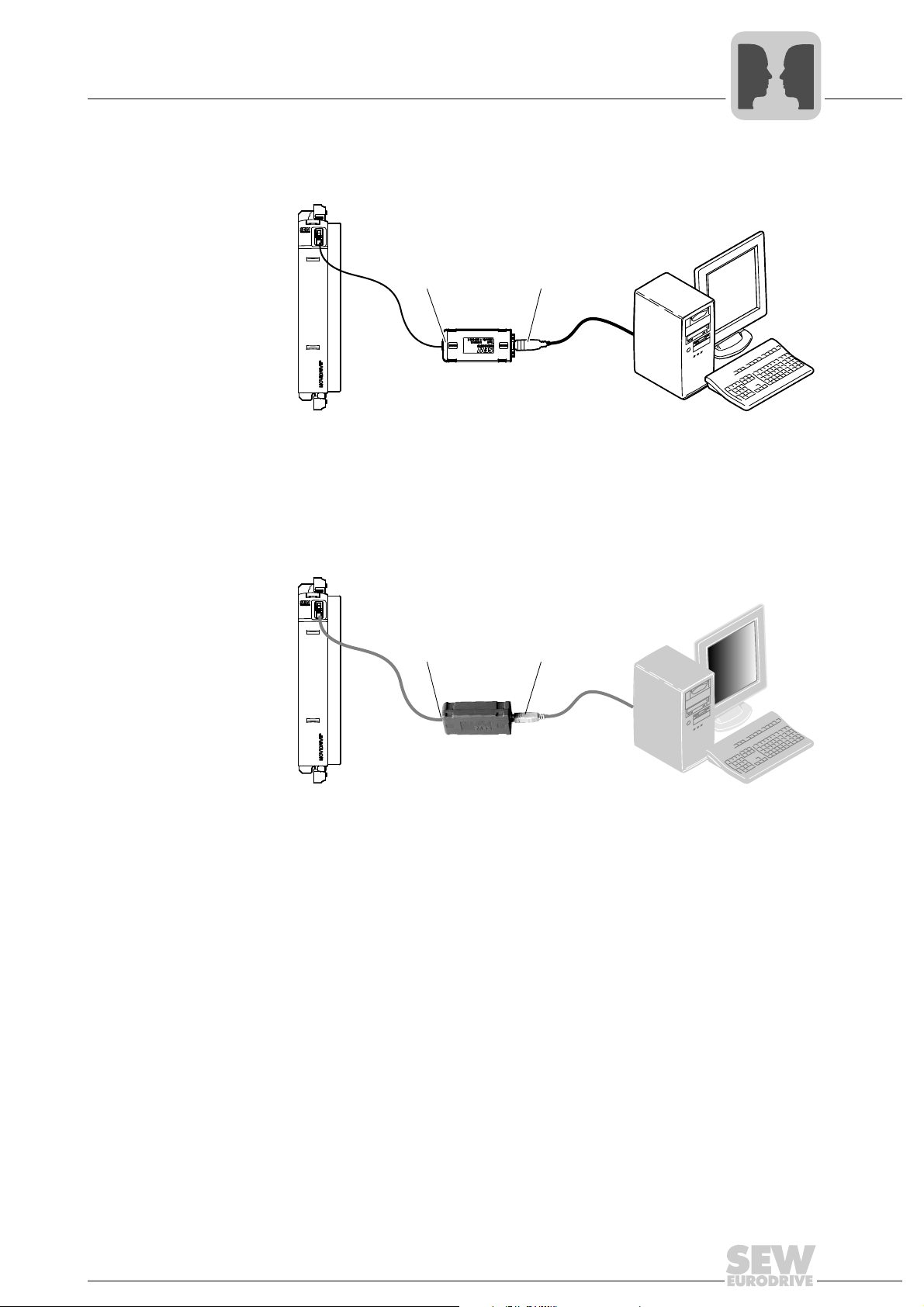
USB11A
COM 1-99
MOVIDRIVE
®
MDX60/61B
[1] [2]
Connecting and installing RS485 interfaces
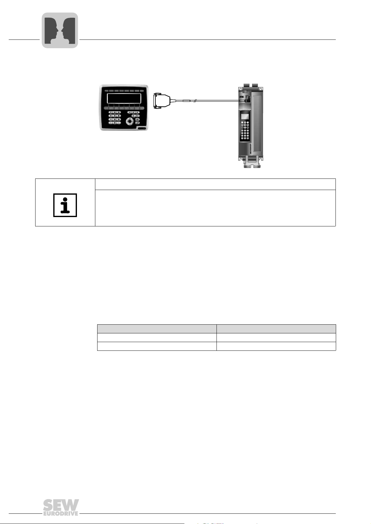
• UWS21B interface adapter (RS485 signals [1] to RS232 signals [2])
MOVIDRIVE® MDX60/61B
COM 1-99
[1] [2]
UWS21B
®
The UWS21B option is used to equip a MOVIDRIVE
interface. The RS232 interface is designed as a 9-pole sub-D socket (EIA standard).
A Sub D9 extension cable (1:1 connection) is supplied for connection to the PC.
B with a potential-free RS232
4
64306AXX
• USB11A interface adapter (RS485 signals [1] to USB signals [2])
You can use the USB11A option for potential-free connection of a MOVIDRIVE
to an engineering PC via USB. When installing the USB driver, a virtual COM port is
created in the PC for communication with MOVIDRIVE
®
B.
64297AXX
®
B
Manual – MOVIDRIVE® MDX60B/61B Communication and Fieldbus Unit Profile
13
4
MOVIDRIVE® B
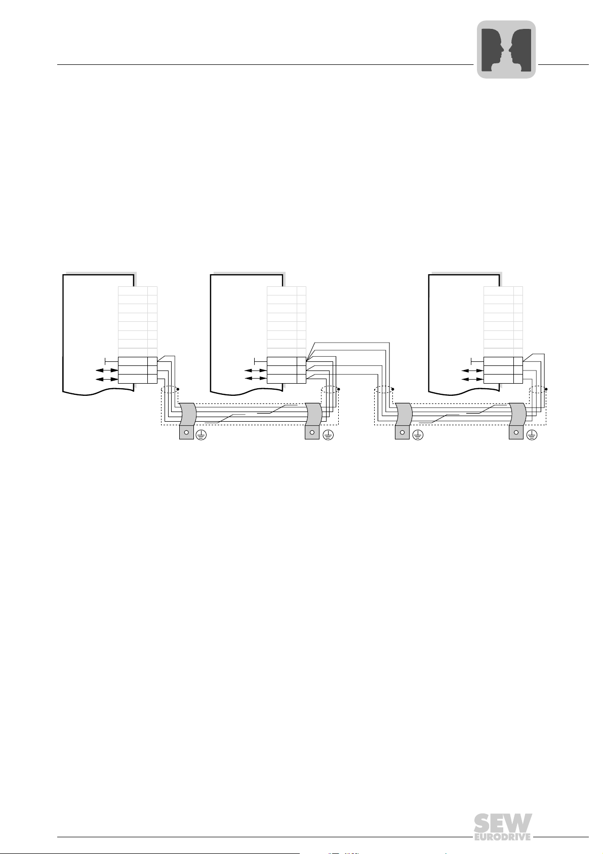
DOP11B
PCS21A
Serial Interfaces of MOVIDRIVE® B
Connecting and installing RS485 interfaces
• DOP11B operator terminal
64282AXX
TIP
The DBG60B, UWS21B and USB11A options are connected to the XT socket. The
options cannot be used at the same time.
Electrical
isolation
Terminating
• The serial interface XT is not electrically isolated. It must be used for point-to-point
connections only.
• Matching terminating resistors are integrated in all SEW components.
resistor
Cable length • Maximum cable length: 3 m (5 m for shielded cables)
Baud rate • The baud rate for RS485 communication is set using DIP switch S13 (on the front of
MOVIDRIVE
Baud rate DIP switch S13
9.6 kBaud ON
57.6 kBaud
1) Factory setting
®
B beneath the XT socket).
1)
OFF
1)
The set baud rate takes effect once the DIP switch position has been changed.
14
Manual – MOVIDRIVE® MDX60B/61B Communication and Fieldbus Unit Profile
Serial Interfaces of MOVIDRIVE® B
X13:
X13:
X13:
DGND
ST11
ST12
DGND
ST11
ST12
DGND
ST11
ST12
DIØØ
DIØ1
DIØ2
DIØ3
DIØ4
DIØ5
DCOM
VO24
DIØØ
DIØ1
DIØ2
DIØ3
DIØ4
DIØ5
DCOM
VO24
DIØØ
DIØ1
DIØ2
DIØ3
DIØ4
DIØ5
DCOM
VO24
9
10
11
9
10
11
9
10
11
1
2
3
4
5
6
7
8
1
2
3
4
5
6
7
8
1
2
3
4
5
6
7
8
RS485-
RS485-
RS485-
RS485+
RS485+ RS485+
Connecting and installing RS485 interfaces
4.1.2 Connection using terminals X13:10 and X13:11
4
Another RS485 interface is provided via terminals X13:10 and X13:11. This RS485
interface can be used to interconnect several MOVIDRIVE
other options at the same time.
• Interface adapter UWS11A (RS232 signals to RS485 signals)
• DOP11B operator terminal
• Other SEW drives, such as MOVIMOT
• Other interface adapters, such as COM server or other RS485 master devices
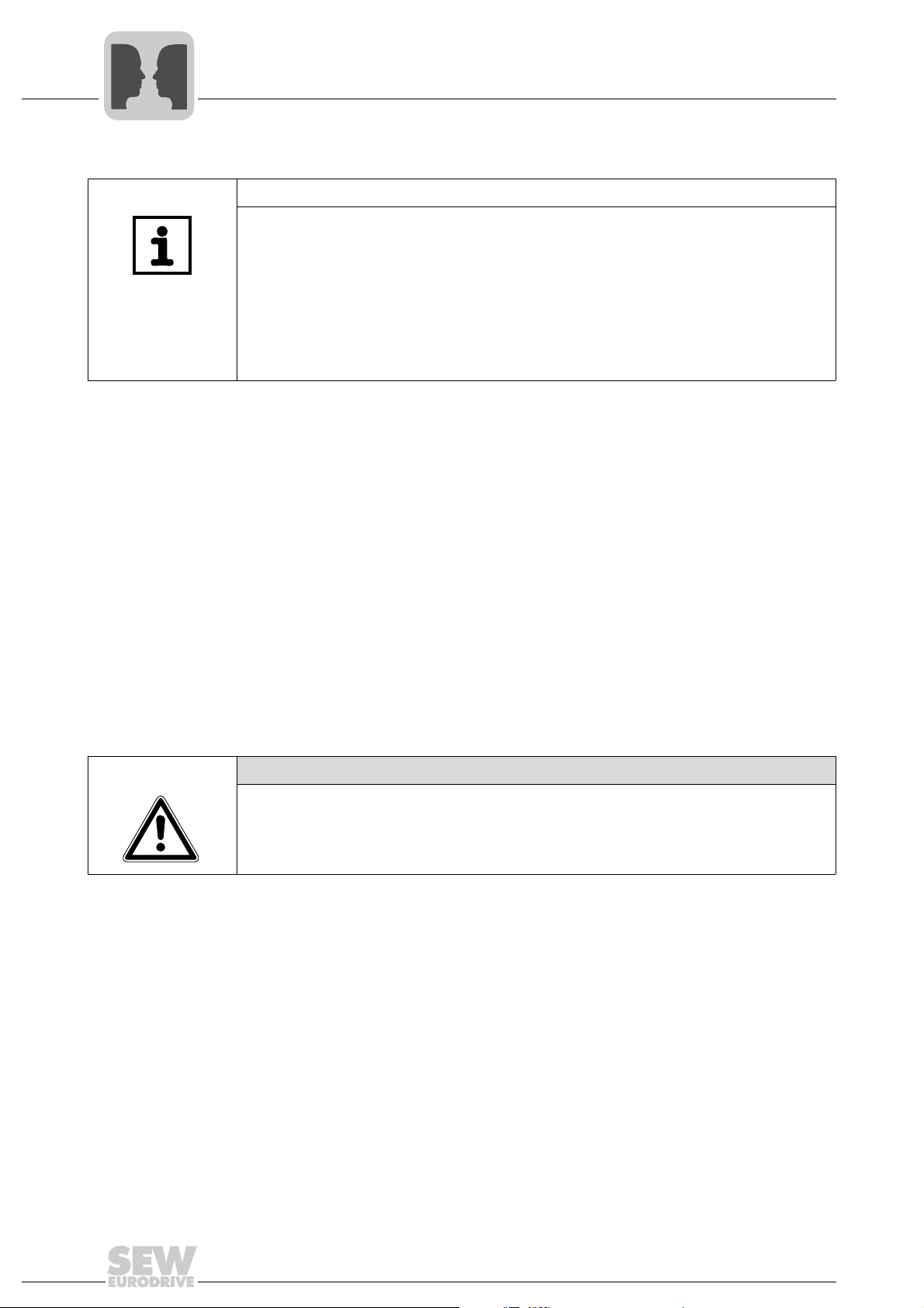
Wiring diagram of the RS485 interface (X13)
®
B units and connect the
®
Electrical isolation • The RS485 interface X13 is not electrically isolated. Do not connect more than 32
MOVIDRIVE
®
B units with one another,
Cable specification • Use a 4 core twisted pair and shielded copper cable (data transmission cable with
braided copper shield). The cable must meet the following specifications:
– Cable cross section 0.25 - 0.75 mm
2
(AWG 23 - AWG 19)
– Cable resistance 100 - 150 Ω at 1 MHz
– Capacitance per unit length ≤ 40 pF/m at 1 kHz
Cable length • The permitted total cable length is 200 m (656 ft).
Shielding • Connect the shield to the electronics shield clamp on the inverter or higher-level
controller and make sure it is connected over a wide area at both ends.
Baud rate • The baud rate is set to 9.6 baud by default.
Terminating
resistor
• Dynamic terminating resistors are installed. Do not connect any external terminat-
ing resistors.
54535AXX
Manual – MOVIDRIVE® MDX60B/61B Communication and Fieldbus Unit Profile
15
4
Serial Interfaces of MOVIDRIVE® B
Connecting and installing RS485 interfaces
TIPS
• When interconnecting the units, make sure that always only one master (e.g.
• Operating several masters on an RS485 network with SEW drives is not permitted
• There must not be any potential displacement between the units connected via the
4.1.3 Shielding and routing cables
Correct shielding of the bus cable attenuates electrical interference that can occur in
industrial environments. The following measures ensure the best possible shielding:
• Manually tighten the mounting screws on the connectors, modules, and equipotential
• Apply the shielding of the bus cable on both ends over a large area.
• Route signal and bus cables in separate cable ducts. Do not route them parallel to
• Use metallic, grounded cable racks in industrial environments.
• Route the signal cable and the corresponding equipotential bonding close to each
• Avoid using plug connectors to extend bus cables.
• Route the bus cables closely along existing grounding surfaces.
DOP11B, engineering PC) is connected and active.
(see chapter "MOVILINK
RS485. This may affect the functionality of the units.
Take suitable measures to avoid potential displacement, such as connecting the
unit ground connectors using a separate cable.
bonding conductors.
power cables (motor leads).
other using the shortest possible route.
®
via RS485").
CAUTION
In case of fluctuations in the ground potential, a compensating current may flow via the
bilaterally connected shield that is also connected to the protective earth (PE). Make
sure you supply adequate equipotential bonding according in accordance with relevant
VDE regulations in such a case.
16
Manual – MOVIDRIVE® MDX60B/61B Communication and Fieldbus Unit Profile
Serial Interfaces of MOVIDRIVE® B
Configuration parameters of the serial interfaces
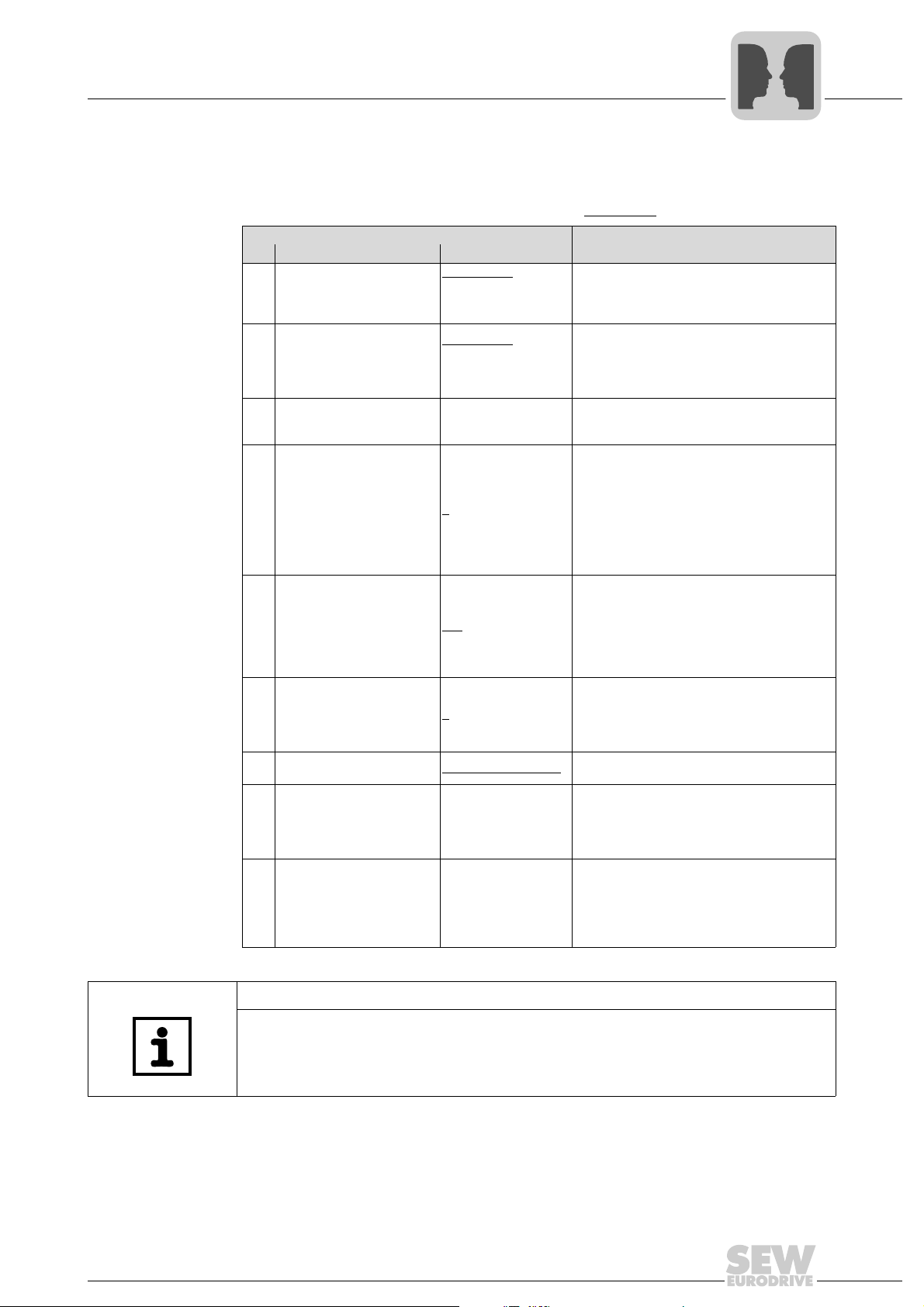
4.2 Configuration parameters of the serial interfaces
The following parameters are used to set communication via the two serial interfaces.
The factory setting of the individual parameters is underlined
Parameter
No. Name Setting Meaning
TERMINALS
100 Setpoint source
101 Control signal source
750 Slave setpoint
810 RS485 Address 0
811 RS485 group address 100
812 RS485 Timeout interval 0
833 Response to RS485 timeout RAPID STOP/WARN.
870
Setpoint description PO1
871
Setpoint description PO2
872
Setpoint description PO3
RS485
FIELDBUS
SBus
TERMINALS
RS485
FIELDBUS
SBus
... 99
... 199
... 650 s
Factory set to:
CONTROL WORD 1
SPEED
NO FUNCTION
.
This parameter is used to set the setpoint
source for the inverter.
This parameter is used to set the source of the
control signals for the inverter (CONTROLLER
INHIBIT, ENABLE, CW, CCW, ...). Control via
plus®
IPOS
disregarding of P101.
The setpoint to be transferred to the master is
set on the master. The "MASTER-SLAVE OFF"
setting must be retained on the slave.
P810 is used to set the address by means of
which communication can take place with
MOVIDRIVE
Note:
MOVIDRIVE
address 0 on delivery. To avoid problems
during data exchange in serial communication
with several inverters, we recommend that you
do not use address 0.
P811 allows for grouping several MOVIDRIVE
B units in one group for communication via the
serial interface. For example, the RS485 group
address allows for sending setpoint selections
to a group of MOVIDRIVE
neously. Group address 100 means that the
inverter is not assigned to a group.
P811 sets the monitoring time for data transmission via the serial interface. No monitoring
of serial data transmission takes place when
P812 is set to 0. Monitoring is activated with the
first cyclical data exchange.
P833 programs the fault response that is triggered by the RS485 timeout monitoring.
P870/P871/P872 define the content of the process output data words PO1/PO2/PO3.
and terminal is taken into account
®
via the serial interfaces.
®
B units are always set to the
®
B inverters simulta-
4
®
Factory set to:
Actual value description PI1
873
Actual value description PI2
874
Actual value description PI3
875
Enable PO data
876
STATUS WORD 1
SPEED
NO FUNCTION
ON
The content of process input data words
PI1/PI2/PI3 is defined.
TIP
Refer to the MOVIDRIVE® MDX60B/61B system manual for a detailed description of
the parameters.
Manual – MOVIDRIVE® MDX60B/61B Communication and Fieldbus Unit Profile
17

4
01234567
LSB MSB even
Start
Parity
Stop
Start
Character
8 data bits
Serial Interfaces of MOVIDRIVE® B
MOVILINK® protocol via RS485 transmission method
4.3 MOVILINK® protocol via RS485 transmission method
4.3.1 Transmission method
An asynchronous, serial transmission method is used which is supported by the UART
modules common in digital technology. This means the MOVILINK
implemented in nearly all controllers and master modules.
®
protocol can be
Characters Each character in the MOVILINK
lows:
• 1 start bit
• 8 data bits
• 1 parity bit, completing for even parity (even parity)
•1 stop bit
Each transmitted character begins with a start bit (always logical 0). The start bit is followed by 8 data bits and the parity bit. The parity bit is set in such a way that the number
of logical ones in the data bits including the parity bit is even-numbered. The last bit of
a character is a stop bit, which is always set to logical level 1. This level remains on the
transmission medium until a new start bit signals the transmission of another character.
®
protocol consists of 11 bits and is structured as fol-
Transmission
rate and
transmission
mechanisms
Response delay of
the master
Start delimiter
(idle)
Character delay The interval between the time when a character of a telegram is sent must be shorter
18
The transmission rate is 9600 baud or 57.6 kBaud (via XT only). The communications
link is monitored by the master and the inverter itself. The master monitors the response
delay time. The inverter monitors the reception of cyclic request telegrams of the master.
A response delay is usually programmed on the higher-level master system. The
response delay is the interval between the time when the last character of the request
telegram is sent (BCC) and the time when the response telegram is sent (SD2). The
maximum permitted response delay interval is 50 ms. A transmission error has occurred
if the inverter does not respond within this interval. Check the interface cable and the
coding of the sent request telegram. Depending on the application, the request telegram
should now be repeated and the next inverter be addressed.
To interpret a character as start delimiter (02
pause of at least 3.44 ms.
than the time preceeding the start delimiter (which means max. 3.43 ms). Else, the
telegram is invalid.
Manual – MOVIDRIVE® MDX60B/61B Communication and Fieldbus Unit Profile
hex
or 1D
), it must be preceeded by a
hex
64767AEN
Serial Interfaces of MOVIDRIVE® B
MOVILINK® protocol via RS485 transmission method
4
RS485 timeout
interval of the
inverter
For MOVIDRIVE®, the maximum permitted time inverval between two cyclic request
telegrams is set using parameter P812 RS485 Timeout interval. The system must
receive a valid request telegram during this time period. Else, the inverter will trigger an
RS485 timeout error and execute a defined error response.
After power on or a fault reset, MOVIDRIVE
first request telegram is received. When the inverter is enabled, "t" (= timeout active)
appears on the 7-segment display and the enable is ineffective. Only when the first telegram is received, enable will take effect and the drive is set in motion.
If the inverter is controlled via RS485 interface (P100 "Setpoint source" = RS485 / P101
"Control signal source" = RS485) and a fault response with warning was programmed,
the last received process data will be active after an RS485 timeout and reestablished
communication.
®
is maintained in a safe condition until the
NOTICE
If a timeout is not recognized, the drive will continue to move despite disconnected
controller.
Possible consequences: Damage to the system.
Only one of the two RS485 must be used for timeout monitoring.
RS485 timeout is active for both RS485 interfaces. Therefore, timout monitoring for the
second interface has no effect with plugged-in DBG60B keypad. The DBG60B keypad
permanently sends request telegrams to the inverter and in this way triggers the timeout mechanism.
Manual – MOVIDRIVE® MDX60B/61B Communication and Fieldbus Unit Profile
19
4
Serial Interfaces of MOVIDRIVE® B
MOVILINK® protocol via RS485 transmission method
Processing
request/response
telegrams
The inverter only processes request telegrams that were received without errors and
were correctly addressed. The following reception errors are detected:
• Parity error
• Character frame error
• Exceeded character delay of request telegrams
• Incorrect address
• Incorrect PDU type
• Incorrect BCC
• RS485 timeout (slave)
• Elapsed response time (master)
The inverter does not respond to incorrectly received request telegrams! These
reception errors have to be evaluated in the master to ensure correct data transmission.
TIPS
If RS485 or RS232 communication is to be transmitted via gateways, COM server, or
modem connections, make sure that not only the character (start bit, 8 data bits, 1 stop
bit, even parity) is correct but also that start delimiter and character delay time are
complied with:
• Max. character delay of 3.43 ms between 2 characters of a telegram
• Min. 3.44 pause before the start delimiter
Else, the individual characters cannot be clearly assigned to the various telegrams.
20
Manual – MOVIDRIVE® MDX60B/61B Communication and Fieldbus Unit Profile

4.3.2 Telegrams
Serial Interfaces of MOVIDRIVE® B
MOVILINK® protocol via RS485 transmission method
4
Telegram
transmission
Cyclical data
exchange
Acyclical data
exchange
Telegram
structure
Both cyclic and acyclic data exchange is used in drive engineering. Cyclic telegrams via
the serial interface are mainly used for drive control in automation tasks. In this case,
the master station has to ensure cyclic data exchange.
Cyclic data exchange is mainly used for controlling inverters via the serial interface. The
master continuously sends telegrams with setpoints (request telegrams) to an inverter
(slave) and expects a response telegram with actual values from the inverter. Once the
request telegram is sent to an inverter, the master expects the response telegram within
a defined time (response delay time). The inverter will only send a response telegram if
it has correctly received a request telegram with its slave address. During cyclic data
exchange, the inverter monitors data communication and triggers a timeout response if
it has not received another request telegram from the master within a specified time.
MOVILINK
communication without having to change the telegram type.
Acyclic data exchange is primarily used for startup and diagnostic purposes. In this
case, the inverter does not monitor the communication connection. In acyclic mode, the
master can send telegrams to the inverter at irregular intervals.
Data exchange is carried out with only two telegram types. The master sends a request
with data in the form of a request telegram to the inverter. The inverter responds with a
response telegram. In case of word information (16 bit) within user data, always the high
byte will be sent first followed by the low byte. In case of double-word information (32
bit), always the high byte will be sent first, followed by the low word. The protocol does
not include coding of the user data. The content of user data is explained in detail in the
"SEW unit profile" chapter.
®
allows for performing acyclic service and diagnostic tasks during cyclic
Manual – MOVIDRIVE® MDX60B/61B Communication and Fieldbus Unit Profile
21

4
....Idle...
SD1
ADR
TYP
PDU BCC
Start delimiter 1
02 hex
PDU type
Block check character
Start pause Slave address Protocol data unit
....Idle...
SD2
ADR
TYP
PDU BCC
Start delimiter 2
02 hex
PDU type
Block check character
Start pause Slave address Protocol data unit
Serial Interfaces of MOVIDRIVE® B
MOVILINK® protocol via RS485 transmission method
Structure of the
request telegram
Structure of the
response telegram
The following figure shows the structure of the request telegram, which the master
sends to the inverter. Each telegram starts with an idle time on the bus, the so-called
start pause, followed by a start delimiter. Different start characters are used to clearly
distinguish between request and response telegrams. The request telegram begins with
the start character SD1 = 02hex, followed by the slave address and PDU type.
01485BEN
The following figure shows the structure of the response telegram, which the inverter
(slave) sends as response to a request from the master. Each response telegram begins
with a start pause, followed by a start delimiter. To clearly distinguish request and response telegrams, the response telegram begins with the start character SD2 = 1Dhex,
followed by the slave address and PDU type.
Start characters
(SD1 / SD2)
22
The start character identifies the beginning and direction of data of a new telegram. The
following table depicts the assignment of start character to direction of data.
SD1 02
SD2 1D
hex
hex
Manual – MOVIDRIVE® MDX60B/61B Communication and Fieldbus Unit Profile
Request telegram Master → inverter
Response telegram Inverter → master
01487BEN
Serial Interfaces of MOVIDRIVE® B
Master
Slave SlaveSlave
ADR: 1 ADR: 3
ADR: 12
Inverter Inverter
Inverter
Request to ADR 12
Response from ADR 12
Request to ADR 3
Response from ADR 3
Request to ADR 1
Response from ADR 1
MOVILINK® protocol via RS485 transmission method
4.3.3 Addressing and transmission method
4
Address byte
(ADR)
The address byte indicates the slave address independent of the direction of data. This
means the ADR character in a request telegram specifies the address of the inverter that
is to receive the request. In opposite direction, the master recognizes the inverter that
has sent the response telegram. The master is not addressed because the system is
generally a single-master system. The MOVILINK
®
protocol offers other addressing
variants in addition to single addressing. The table below shows the address ranges and
what they mean.
ADR Meaning
0-99 Single addressing within the RS485 bus.
100 - 199
253
254 Universal address for point-to-point communication.
255 Broadcast address. No response is sent.
Group addressing (multicast)
Special case group address 100: "Meaning not assigned to any group", i.e. not effective.
plus®
Local address: Only effective in conjunction with IPOS
command. For unit internal communication
as master and the MOVILINK®
TIP
MOVIDRIVE® basically is a slave unit. However, master functions are also available
using IPOS
plus®
, the MOVILINK® command, and the master/slave function.
Single addressing Every inverter can be directly addressed using addresses 0 - 99. The inverter responds
to every request telegram from the master with a response telegram.
01488BEN
Manual – MOVIDRIVE® MDX60B/61B Communication and Fieldbus Unit Profile
23
4
Master
Slave Slave Slave Slave Slave Slave
ADR: 1 ADR: 2 ADR: 3 ADR: 4 ADR: 5 ADR: 6
Inveter
Inverter Inverter
Inverter
Inverter
Inverter
Group
adr.: 101
Group
adr.: 101
Group
adr.: 101
Group
adr.: 101
Group
adr: 102
Group
adr.: 102
Request telegram to group adr. 102
Request telegram to group adr. 101
Master
Slave
ADR: 1
Inverter
Request telegram via universal adr. 254
Response telegram from slave
Serial Interfaces of MOVIDRIVE® B
MOVILINK® protocol via RS485 transmission method
Group addressing
(multicast)
Every inverter has a setable group address in addition to its individual address. In this
way, the user can group various participants and address the individual participants of
a group simultaneously using group addressing. With group addressing, the master
does not receive a response telegram. This means that no data can be requested from
the inverter. And there is no response when writing data. A maximum of 99 groups can
be set up.
Universal addressing for point-topoint communication
01489BEN
Basically, every inverter can be addressed using universal address 254 independent of
the set single address. The advantage of this variant is that point-to-point connections
can be established without having to know the individual address. As each inverter of
the group is addressed using this universal address, it must not be used for multi-point
connections (e.g. RS485 bus). Else, data collisions would occur on the bus because
every inverter would send a response telegram once it receives a request telegram.
01490BEN
24
Manual – MOVIDRIVE® MDX60B/61B Communication and Fieldbus Unit Profile
Serial Interfaces of MOVIDRIVE® B
Master
Slave Slave Slave Slave Slave Slave
ADR: 1 ADR: 2 ADR: 3 ADR: 4 ADR: 5 ADR: 6
Inveter
Inverter Inverter
Inverter
Inverter
Inverter
Group
adr.: 101
Group
adr.: 101
Group
adr.: 101
Group
adr.: 101
Group
adr: 102
Group
adr.: 102
Request telegram to all slaves via broadcast adr. 255
MOVILINK® protocol via RS485 transmission method
Broadcast address Broadcast address 255 can be used to address all inverter stations. The request
telegram with broadcast address 255 sent by the master is received by all inverters but
is not responded to. This means, this addressing method is mainly used to transmit
setpoints. The master can send broadcast telegrams at a minimum interval of every
25 ms. Consequently, an idle time of at least 25 ms is mandatory between the last sent
character of a request telegram (BCC) and the start of a new request telegram (BCC).
4
01491BEN
Manual – MOVIDRIVE® MDX60B/61B Communication and Fieldbus Unit Profile
25
4
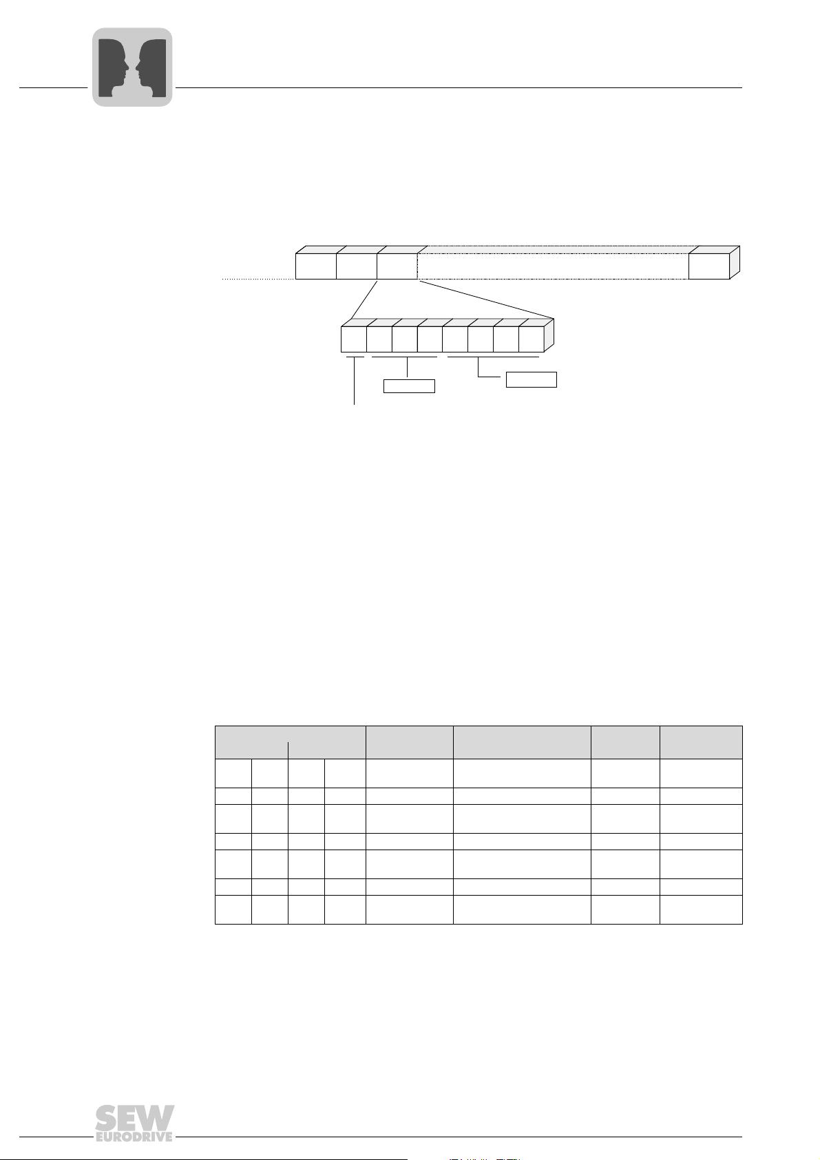
...Idle... SD1 ADR TYP PDU BCC
Bit: 7 6 5 4 3 2 1 0
PDU type
reserved
transmission variant
0: cyclical
1: acyclical
Serial Interfaces of MOVIDRIVE® B
MOVILINK® protocol via RS485 transmission method
4.3.4 Structure and length of user data
PDU type (TYPE) The TYPE byte describes the structure and length of subsequent user data (protocol
data unit (PDU)). The figure below shows the structure of the TYPE byte.
Besides, bit 7 of the TYPE byte indicates whether the user data are transmitted cyclically
or acyclically. A request telegram with cyclic transmission method signals the inverter
that the data sent by the master is updated cyclically. Consequently, response monitoring can be triggered in the inverter. This means if the inverter does not receive a new
cyclic request telegram within a timeout time, which can be set, a timeout response will
be triggered.
The following tables show the PDU types for cyclic and acyclic transmission. The
telegram length depends on the PDU type used and is calculated as follows:
Telegram length = PDU length + 4.
Transmission
methods
The following tables show the PDU types for ACYCLIC and CYCLIC transmission
methods.
TYPE byte PDU name Description PDU length
Cyclic Acyclic
00
hex0dec
01
hex1dec
02
hex2dec
03
hex3dec
04
hex4dec
05
hex5dec
06
hex6dec
80
81
82
83
84
85
86
hex
hex
hex
hex
hex
hex
hex
128
129
130
131
132
133
134
PAR A M + 1PD
dec
dec
PAR A M + 2PD
dec
dec
PAR A M + 3PD
dec
dec
PAR A M + 0PD
dec
1PD 1 process word 2 6
2PD 2 process data words 4 8
3PD 3 process data words 6 10
8 byte parameter channel +
1 process data word
8 byte parameter channel +
2 process data words
8 byte parameter channel +
3 process data words
8 byte parameter channel
without process data
The standard PDU types consist of the MOVILINK
data channel. For the coding of the parameter channel and process data, refer to
chapter "SEW unit profile".
01492BEN
in bytes
10 14
12 16
14 18
®
parameter channel and a process
Tel egr am
length in bytes
812
26
Manual – MOVIDRIVE® MDX60B/61B Communication and Fieldbus Unit Profile
Serial Interfaces of MOVIDRIVE® B
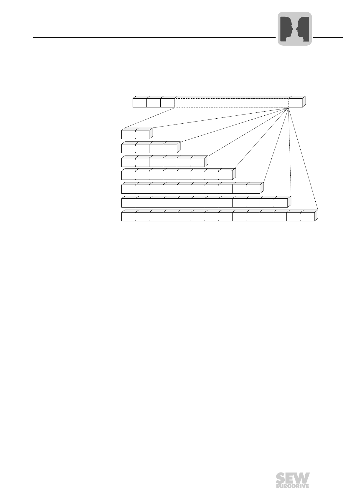
...Idle... SD1 ADR TYP PDU BCC
TYP 1/129
TYP 3/131
TYP 5/133
TYP 6/134
TYP 0/128
TYP 2/130
TYP 4/132
PD1
PD1
PD1
PD1
PD2
PD2
PD1
PD1
PD2
PD2
PD3
PD3
8 byte parameter channel
8 byte parameter channel
8 byte parameter channel
8 byte parameter channel
MOVILINK® protocol via RS485 transmission method
The following figure shows the structure of a request telegram with the standard PDU
types. The associated response telegram has the same structure except for the SD2
start character.
4
Block check character
Transmission
reliability
Transmission reliability with the MOVILINK
character parity and block parity. The parity bit is set for each character of the telegram
in such a way that the number of binary ones including the parity bit is even-numbered.
Block parity provides for additional reliability and means that a block check character
(BCC = Block Check Character) is added to the telegram. Each bit of the block check
character is set in such a way that the result is an even parity for all information bits of
the same value of the telegram character. In programming, the block parity is implemented by EXORing all telegram characters. The result is entered in the BCC at the end
of the message. The block check character itself is also ensured with the even character
parity.
01493BEN
®
protocol is increased by a combination of
Manual – MOVIDRIVE® MDX60B/61B Communication and Fieldbus Unit Profile
27
4
SD1: 02 hex
ADR: 01 hex
TYP: 05 hex
PD1 high: 00 hex
PD1 low: 06 hex
PD2 high: 3A hex
PD2 low: 98 hex
PD3 high: 01 hex
PD3 low: F4 hex
57 hex
Stop
Parity
Start
1
1
0
0
0
0
1
1
1
1
0
0
0
0
0
0
1
0
1
0
0
0
0
0
0
0
0
0
1
1
0
0
0
0
0
1
0
0
1
0
0
0
0
0
0
1
1
0
1
1
0
0
0
0
0
1
1
0
0
0
0
0
1
0
1
0
0
0
1
1
1
0
0
0
1
1
0
0
0
1
0
1
1
0
0
0
0
1
0
1
EXOR
EXOR
EXOR
EXOR
EXOR
EXOR
EXOR
EXOR
calculated BCC:
Serial Interfaces of MOVIDRIVE® B
MOVILINK® protocol via RS485 transmission method
Creating the block
check character
The following figure gives an example of how a block check character is created for a
cyclical telegram of type PDU 5 with 3 process data words. The EXOR logic operation
of the characters SD1 - PD3
results in the value 57
low
as the block check character
hex
BCC. This block check character will be sent as the last character of the telegram. The
recipient checks the character parity after having received the individual characters.
Next, the block check character is created from the received characters SD1 - PD3
low
according to the pattern described above. The telegram has been correctly transmitted
if the calculated and received block check characters are identical and there is no
character parity error. Any other result will be displayed as a transmission error.
28
TIP
For a description of process data and the structure of the 8-byte parameter data
channel, refer to chapter "SEW unit profile".
Manual – MOVIDRIVE® MDX60B/61B Communication and Fieldbus Unit Profile
01494BEN
Serial Interfaces of MOVIDRIVE® B
Other unit functions via RS485 interfaces
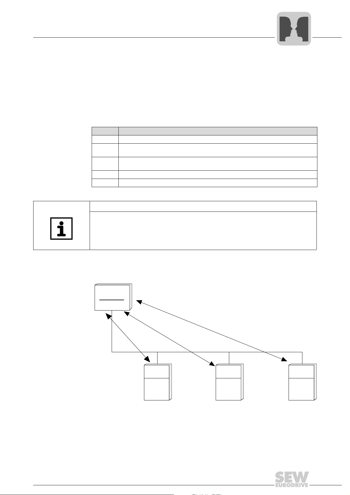
4.4 Other unit functions via RS485 interfaces
4
In addition to process and parameter data exchange between PC, keypad and
MOVIDRIVE
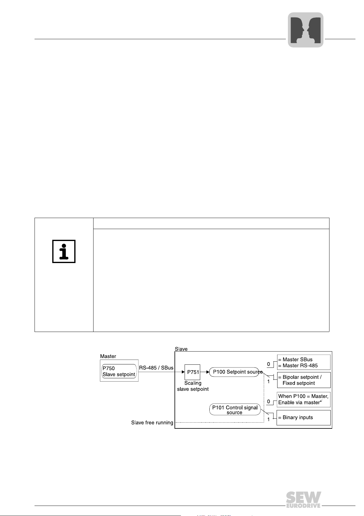
• Master/slave operation
•IPOS
• Manual operation
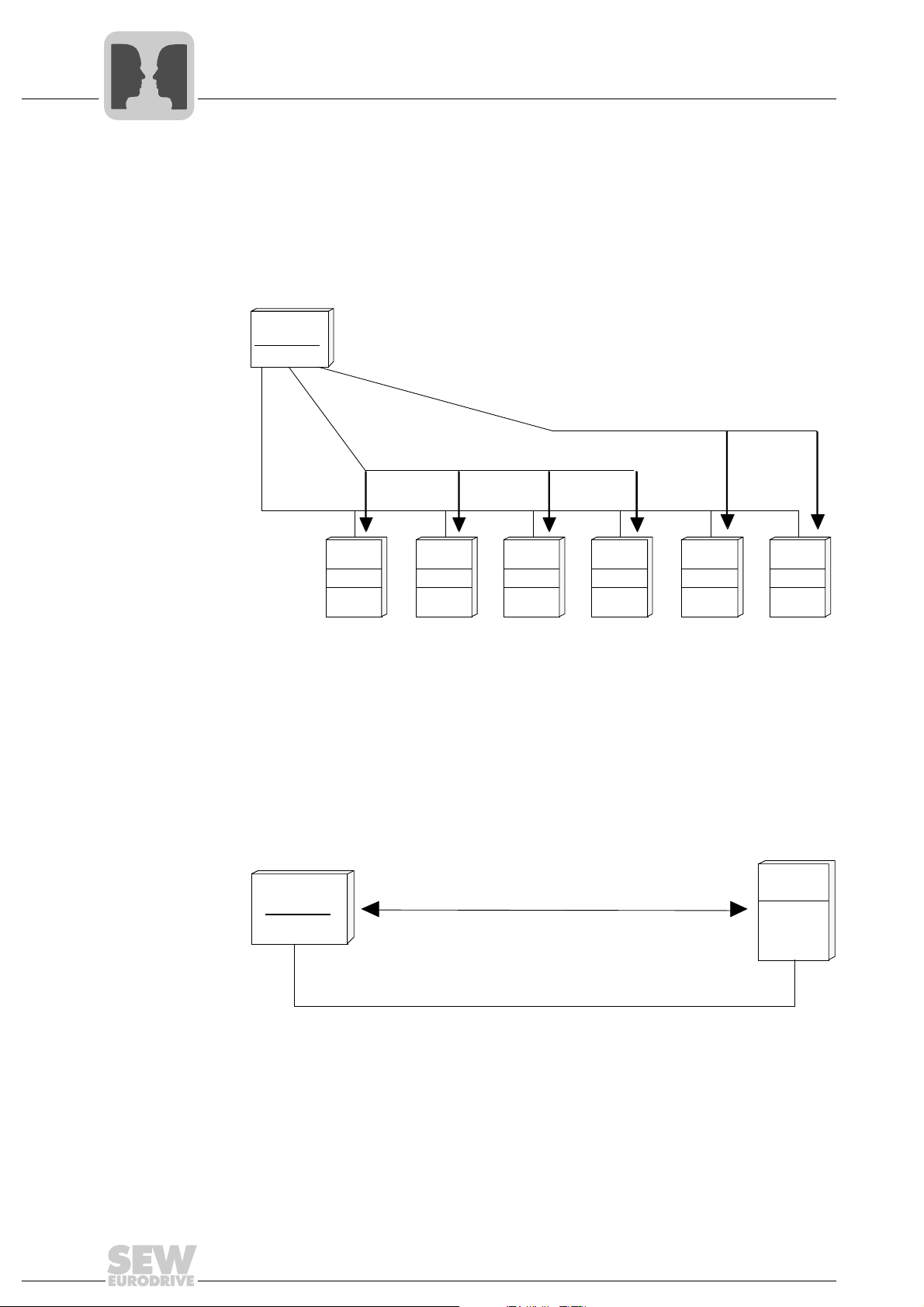
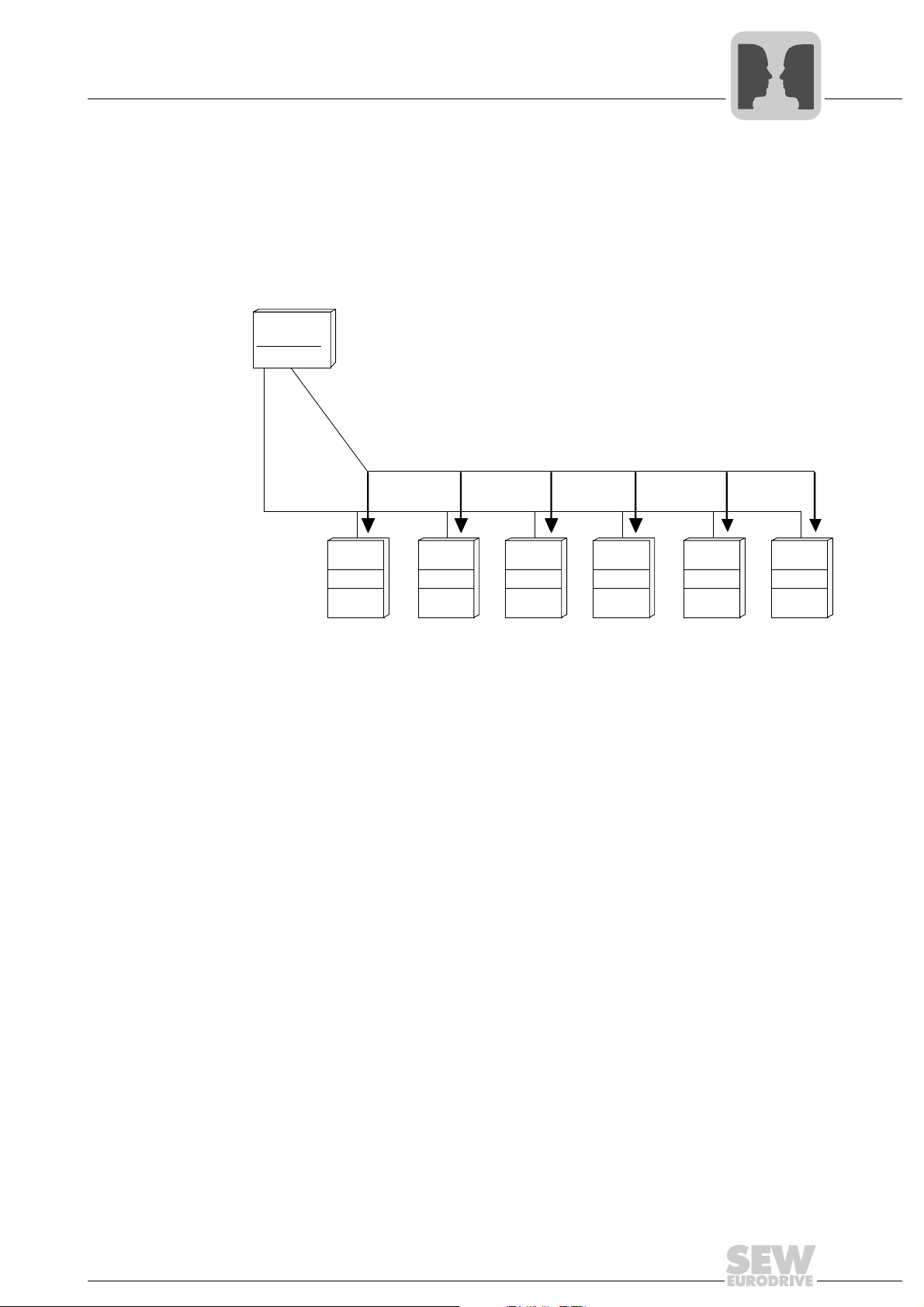
4.4.1 Using RS485 interfaces for master/slave operation
The master/slave function shown in the figure below allows for implementing automatic
functions such as speed synchronization, shared load and torque control (slave). The
RS485 interface (X13:10/X13:11) or the system bus interface (CAN 1) can be used as
communication link. P100 Setpoint source = Master SBus or P100 Setpoint source =
Master RS485 must be set on the slave. The process output data PO1 - PO3 (P870,
P871, P872) are automatically set by the firmware. A programmable terminal function
"Slave free run. "P60x binary inputs basic unit /P61x binary inputs option, it is possible
to separate the slave from the master setpoint and switch to local control mode.
®
B, the RS485 interfaces can also be used for the following functions:
plus®
TIP
For the slave, the process data P87x are automatically assigned as follows:
– PO1 = Control word 1
– PO2 = Speed or current in M-control
– PO3 = IPOS PO data
– PI1 = Status word 1
– PI2 = Speed
– PI3 = IPOS PI data
PI3 and PO3 are not used. They are available in IPOS
If a fieldbus card is plugged in the slave, only the parameter channel is available for the
output data. The master can read the automatically assigned process input data via
fieldbus.
plus®
as required.
*) DIØØ "/Controller inhibit" and the programmed binary inputs Enable, CW and CCW
must also receive a "1" signal.
Manual – MOVIDRIVE® MDX60B/61B Communication and Fieldbus Unit Profile
01311BEN
29
4
Serial Interfaces of MOVIDRIVE® B
Other unit functions via RS485 interfaces
TIP
P811 RS485 group address must be set to the same value for master and slave. For
master/slave operation via RS485 interface, set P811 RS485 Group address to a value
greater than 100. If you have made the setting in parameter P750 slave setpoint that
slave setpoints are used via RS485, then MOVIDRIVE
quests (process and parameter telegrams) from another RS485 master (P100/101 ≠
RS485) as slave via this RS485 interface.
®
can no longer respond to re-
Connection
check
A connection check is always active for communication link via RS485 interface. P812
RS485 timeout interval is without function. The slave inverters must receive a valid
RS485 telegram within the fixed time interval of t = 500 ms. If the time is exceeded, the
slave drives will stop at the emergency stop ramp and error message F43 "RS485
timeout" will be issued.
NOTICE
If a timeout is not recognized, the drive will continue to move despite disconnected
controller.
Possible consequences: Damage to the system.
Only one of the two RS485 interfaces must be used for timeout monitoring.
As the RS485 timeout is active for both RS485 interfaces, the second interface is not
monitored for timeout when the DBG60B keypad is installed. The DBG60B keypad
permanently sends request telegrams to the inverter and in this way triggers the timeout mechanism.
30
Manual – MOVIDRIVE® MDX60B/61B Communication and Fieldbus Unit Profile
 Loading...