

SEW MOVIDRIVE MDX60B, MOVIDRIVE MDX61B System Manual
Drive Technology \ Drive Automation \ System Integration \ Services
System Manual
MOVIDRIVE
Edition 09/2010 16838017 / EN
®
MDX60B/61B

SEW-EURODRIVE—Driving the world

Contents
Contents
1 System Description............................................................................................. 8
1.1 System overview of MOVIDRIVE
1.2 Functions/features .................................................................................... 21
1.3 Additional functions of the application variants ......................................... 24
1.4 Application modules for MOVIDRIVE
1.5 MOVITOOLS
®
MotionStudio engineering software .................................. 37
2 Technical Data of Basic Unit............................................................................ 39
2.1 CE marking, UL approval and C-Tick ....................................................... 39
2.2 General technical data .............................................................................. 40
2.3 MOVIDRIVE
2.4 MOVIDRIVE
2.5 MOVIDRIVE
2.6 MOVIDRIVE
2.7 MOVIDRIVE
2.8 IPOS
plus®
®
MDX60/61B...-5_3 (AC 400/500 V units)........................... 42
®
MDX61B...-2_3 (AC 230 V units)....................................... 51
®
MDX60/61B electronics data ............................................. 55
®
MDX60B dimension drawings............................................ 57
®
MDX61B dimension drawings............................................ 59
.................................................................................................. 69
2.9 DBG60B keypad option ............................................................................ 71
2.10 DBM60B/DKG60B housing option for DBG60B........................................ 73
3 Technical Data of Regenerative Power Supply Units ................................... 74
3.1 MOVIDRIVE
®
MDR60A regenerative power supply units ........................ 74
4 Technical Data of Options ............................................................................... 82
4.1 DEH11B Hiperface
®
encoder card option................................................. 82
4.2 DER11B resolver card option ................................................................... 83
4.3 DEU21B multi-encoder card option .......................................................... 84
4.4 DEH21B/DIP11B absolute encoder card option ....................................... 85
4.5 Connector adapter for unit replacement MD_60A - MDX60B/61B ........... 88
4.6 DWE11B/12B interface adapter option ..................................................... 90
4.7 UWS11A interface adapter option ............................................................ 92
4.8 UWS21B interface adapter option ............................................................ 94
4.9 USB11A interface adapter option ............................................................. 96
4.10 DWI11A DC 5 V encoders supply option ................................................. 98
4.11 DIO11B input/output card option............................................................. 100
4.12 DFP21B PROFIBUS fieldbus interface option ........................................ 102
4.13 DFI11B INTERBUS fieldbus interface option.......................................... 103
4.14 DFI21B INTERBUS optical fiber fieldbus interface option ...................... 104
4.15 DFE32B PROFINET IO RT fieldbus interface option.............................. 105
4.16 DFE33B EtherNet/IP and Modbus/TCP fieldbus interface option........... 107
4.17 DFE24B EtherCAT
®
fieldbus interface option......................................... 109
4.18 DFD11B DeviceNet fieldbus interface option.......................................... 110
4.19 DFC11B CAN/CANopen fieldbus interface option .................................. 111
4.20 DRS11B synchronous operation card option.......................................... 112
®
MDX60B/61B....................................... 8
®
MDX61B...................................... 28
System Manual – MOVIDRIVE® MDX60B/61B
3

Contents
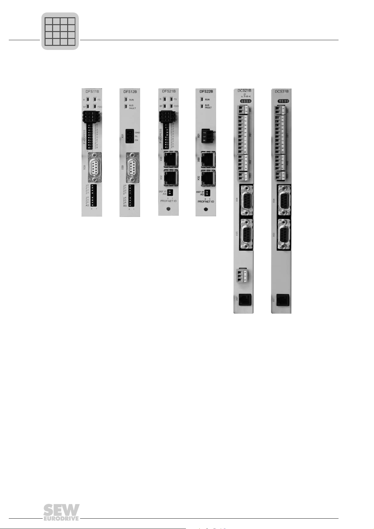
4.21 DFS11B fieldbus interface option PROFIBUS DP-V1 with PROFIsafe .. 113
4.22 DFS12B fieldbus interface option PROFIBUS DP-V1 with PROFIsafe .. 115
4.23 DFS21B fieldbus interface option PROFINET IO with PROFIsafe ......... 116
4.24 DFS22B fieldbus interface option PROFINET IO with PROFIsafe ......... 118
4.25 MOVISAFE
4.26 MOVI-PLC
4.27 OST11B option ....................................................................................... 123
4.28 DHE/DHF/DHR21 and DHE/DHF/DHR41B controller option ................. 124
4.29 BST safety-related brake module option................................................. 130
5 Technical Data of External Accessories ....................................................... 132
5.1 DMP11B mounting panel option ............................................................. 132
5.2 DLB11B touch guard option.................................................................... 133
5.3 DLB21B touch guard option (for size 7).................................................. 134
5.4 DLS11B mounting base option (for size 7) ............................................. 135
5.5 DLH11B wall bracket (for size 7) ............................................................ 136
5.6 DLA11B connection kit option (for size 7)............................................... 137
5.7 DLK11B air duct option (for size 7) ......................................................... 138
5.8 DLZ11B DC link coupling option (for size 7) ........................................... 139
5.9 2Q DLZ12B DC link adapter option (for size 7) ...................................... 140
5.10 4Q DLZ14B DC link adapter option (for size 7) ...................................... 141
®
DCS21B/31B safety module option................................... 119
®
basic DHP11B controller option.......................................... 122
6 Technical Data of Braking Resistors, Chokes and Filters .......................... 142
6.1 BW... braking resistor option / BW...-T / BW...-P .................................... 142
6.2 ND.. line choke option............................................................................. 153
6.3 NF...-... line filter option........................................................................... 155
6.4 HD... output choke option ....................................................................... 159
6.5 HF... output filter option........................................................................... 162
7 Prefabricated Cables ...................................................................................... 166
7.1 Overview ................................................................................................. 166
7.2 Cable sets for DC link connection MDR → MDX .................................... 166
7.3 CM motor cables with connector on motor end ...................................... 167
7.4 CM brakemotor cables with connector on motor end ............................. 168
7.5 CMD/CMP motor cables with connector on motor end........................... 169
7.6 CMP brakemotor cables for BP brake with connector at motor end ....... 169
7.7 CMP brakemotor cables for BY brake with connector at motor end ....... 170
7.8 Encoder cable selection: Meaning of the symbols.................................. 171
7.9 Encoder cables for DR motors on X15 DEH11B/DEH21B/DEU21B ...... 172
7.10 Encoder cable for DT/DV/CMP, CM, (DS) motors on
X15 DEH11B/DEH21B and DEU21B...................................................... 179
7.11 Encoder cables for distance encoders on X14,
DEH11B / DER11B / DEU21B ................................................................ 185
7.12 Encoder cables for resolvers on X15 DER11B ....................................... 190
4
System Manual – MOVIDRIVE® MDX60B/61B

Contents
8 Parameters....................................................................................................... 193
8.1 Menu structure in DBG60B ..................................................................... 194
8.2 Overview of parameters.......................................................................... 194
8.3 Explanation of the parameters ................................................................ 203
8.4 Operating modes .................................................................................... 282
9 Project Planning.............................................................................................. 294
9.1 Schematic procedure .............................................................................. 294
9.2 Control characteristics ............................................................................ 295
9.3 Description of the applications ................................................................ 297
9.4 Basic recommendations for motor selection ........................................... 299
9.5 Motor selection for asynchronous AC motors (VFC) .............................. 300
9.6 Motor selection for asynchronous AC and servomotors (CFC) .............. 316
9.7 Motor selection for synchronous servomotors (SERVO) ........................ 382
9.8 SL2 synchronous linear motors .............................................................. 403
9.9 Overload capacity of the inverter ............................................................ 403
9.10 Braking resistor selection........................................................................ 437
9.11 Connecting AC brakemotors................................................................... 446
9.12 Permitted voltage systems for MOVIDRIVE
9.13 Line contactors and line fuses ................................................................ 447
9.14 Power connection for size 7.................................................................... 448
9.15 Line and motor cables............................................................................. 451
9.16 Group drive in VFC mode ....................................................................... 458
9.17 Connecting explosion-proof AC motors .................................................. 459
9.18 EMC-compliant installation in accordance with EN 61800-3 .................. 460
9.19 HF… output filter type ............................................................................. 463
9.20 Electronics cables and signal generation................................................ 466
9.21 External voltage supply DC 24 V ............................................................ 467
9.22 Parameter set switchover ....................................................................... 469
9.23 Priority of operating states and interrelation between control signals ..... 470
9.24 Limit switches.......................................................................................... 471
10 General Information ........................................................................................ 472
10.1 How to use the operating instructions..................................................... 472
10.2 Structure of the safety notes ................................................................... 472
10.3 Rights to claim under limited warranty .................................................... 473
10.4 Exclusion of liability................................................................................. 473
10.5 Copyright notice ...................................................................................... 473
10.6 Product names and trademarks.............................................................. 473
®
B...................................... 447
11 Safety Notes .................................................................................................... 474
11.1 General information ................................................................................ 474
11.2 Target group ........................................................................................... 474
11.3 Designated use ....................................................................................... 475
11.4 Transportation, storage........................................................................... 475
11.5 Installation............................................................................................... 476
System Manual – MOVIDRIVE® MDX60B/61B
5

Contents
11.6 Electrical connection ............................................................................... 476
11.7 Safe disconnection.................................................................................. 476
11.8 Operation ................................................................................................ 477
12 Unit Structure .................................................................................................. 478
12.1 Type designation, nameplates and scope of delivery ............................. 478
12.2 Scope of delivery .................................................................................... 480
12.3 Size 0 ...................................................................................................... 482
12.4 Size 1 ...................................................................................................... 483
12.5 Size 2S.................................................................................................... 484
12.6 Size 2 ...................................................................................................... 485
12.7 Size 3 ...................................................................................................... 486
12.8 Size 4 ...................................................................................................... 487
12.9 Size 5 ...................................................................................................... 488
12.10 Size 6 ...................................................................................................... 489
12.11 Size 7 ...................................................................................................... 490
13 Installation ....................................................................................................... 492
13.1 Installation instructions for the basic unit ................................................ 492
13.2 Removing/installing the keypad .............................................................. 510
13.3 Removing/installing the front cover......................................................... 511
13.4 Information regarding UL ........................................................................ 513
13.5 Shield clamps.......................................................................................... 516
13.6 Touch guard for power terminals ............................................................ 519
13.7 Wiring diagram for basic unit .................................................................. 524
13.8 Assignment of braking resistors, chokes and filters................................ 530
13.9 Connecting the system bus (SBus 1)...................................................... 535
13.10 Connecting the RS485 interface ............................................................. 536
13.11 Connecting the interface adapter option type DWE11B/12B .................. 538
13.12 Connection of interface adapter option UWS21B (RS232)..................... 540
13.13 Connecting the interface adapter option USB11A .................................. 542
13.14 Option combinations for MDX61B........................................................... 544
13.15 Installing and removing option cards ...................................................... 546
13.16 Connecting encoders and resolvers ....................................................... 548
13.17 Connection and terminal description of the DEH11B
(Hiperface
13.18 Connection and terminal description of the DEH21B option................... 553
13.19 Connection and terminal description of the DEU21B option................... 555
13.20 Connection and terminal description of the DER11B
(resolver) option ...................................................................................... 557
13.21 Connecting external encoders to X:14.................................................... 559
13.22 Connection of encoder options .............................................................. 560
13.23 Connection of incremental encoder simulation ....................................... 566
13.24 Master/slave connection ......................................................................... 567
13.25 Connection and terminal description of the DIO11B option .................... 568
13.26 Connection and terminal description of the DFC11B option ................... 571
®
) option ................................................................................. 550
6
System Manual – MOVIDRIVE® MDX60B/61B

Contents
14 Startup.............................................................................................................. 572
14.1 General startup instructions .................................................................... 572
14.2 Preliminary work and resources.............................................................. 574
14.3 Startup with DBG60B keypad ................................................................. 575
14.4 Operation of MOVITOOLS
14.5 Starting the motor ................................................................................... 589
14.6 Complete parameter list.......................................................................... 595
15 Operation ......................................................................................................... 609
15.1 Operating Displays.................................................................................. 609
15.2 Information messages............................................................................. 610
15.3 Functions of the DBG60B keypad........................................................... 612
15.4 Memory card ........................................................................................... 616
16 Service ............................................................................................................. 618
16.1 Error information ..................................................................................... 618
16.2 Error messages and list of errors............................................................ 619
16.3 SEW Electronics Service ........................................................................ 637
16.4 Extended storage.................................................................................... 637
16.5 Disposal .................................................................................................. 638
17 Address Directory ........................................................................................... 639
®
MotionStudio.............................................. 585
Index................................................................................................................. 659
System Manual – MOVIDRIVE® MDX60B/61B
7
1
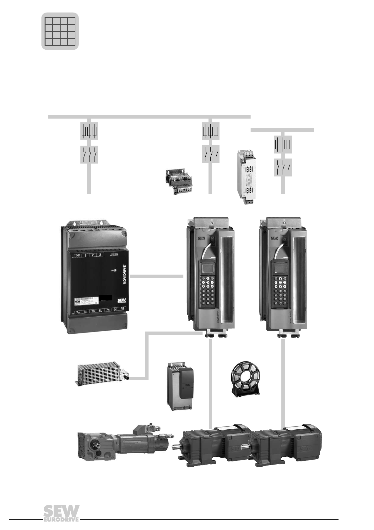
3 x AC 380...500 V
3 x AC 200...240 V
MOVIDRIVE
MDX60/61B...-5_3
®
MOVIDRIVE
MDX61B...-2_3
®
®
Regenerative power supply option
MOVIDRIVE MDR60A
Output
filter option
Output
choke option
Braking
resistor option
Line
filter option
Line
choke option
DC link
P
i
f
kVA
Hz
n
P
i
f
kVA
Hz
n
System Description
System overview of MOVIDRIVE® MDX60B/61B
1 System Description
1.1 System overview of MOVIDRIVE® MDX60B/61B
1.1.1 Power components
1452332683
8
System Manual – MOVIDRIVE® MDX60B/61B
System overview of MOVIDRIVE® MDX60B/61B
MASTER
SLA VE
MOVIT OOL S
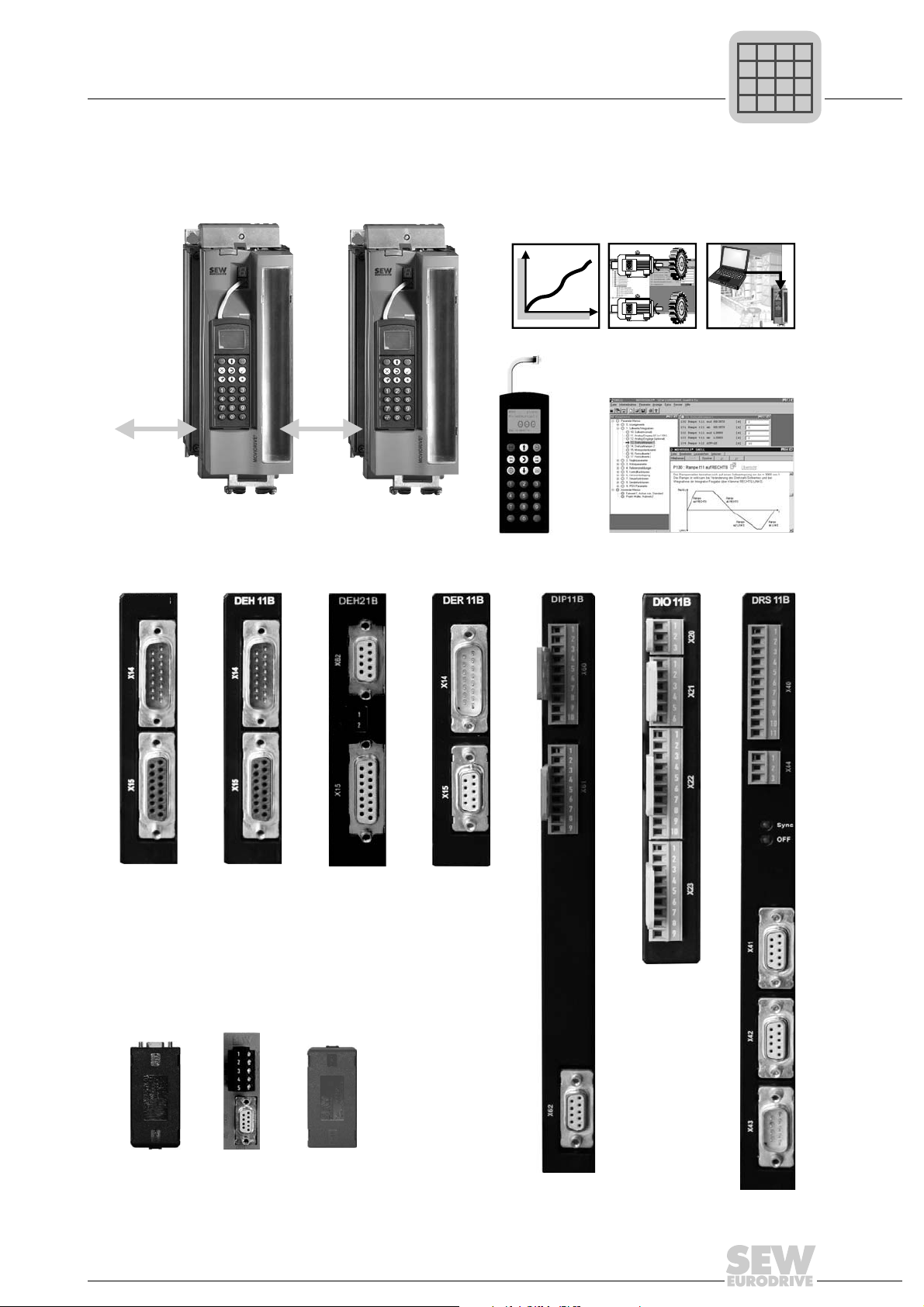
MDX60/61B standard variant with IPOS
plus®
DBG60B keypad option
MDX60/61B application version for
the use of "electronic cam", "Internal
synchronous operation" or the application modules.
System bus
(SBus)
MOVITOOLS® engineering software
Interface adapter option:
Encoder options:
USB 11AUWS 21B
UWS 11A
DEH 11BDEU 21B DEH 21B DER 11B DIP 11B DIO 11B DRS 11B
DEU 21B
P
i
f
kVA
Hz
n
P
i
f
kVA
Hz
n
1.1.2 Encoder and communication options
System Description
1
System Manual – MOVIDRIVE® MDX60B/61B
1452369291
9
1
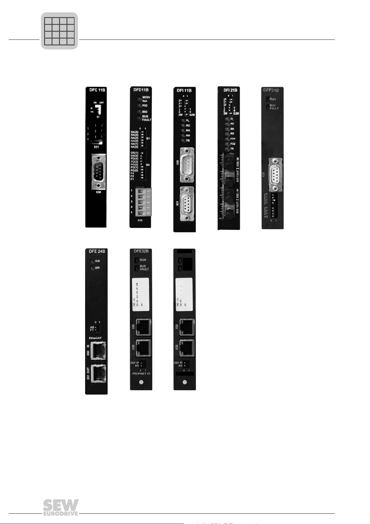
DFC 11B DFD 11B
DFE 32B
DFE 24B
DFI 11B
DFI 21B DFP 21B
DFE 33B
DFE33B
ETHERNET/IP
MODULE
STATUS
NETWORK
STATUS
xx xx xx xx
P
i
f
kVA
Hz
n
P
i
f
kVA
Hz
n
1.1.3 Fieldbus options
System Description
System overview of MOVIDRIVE® MDX60B/61B
1452375307
10
System Manual – MOVIDRIVE® MDX60B/61B
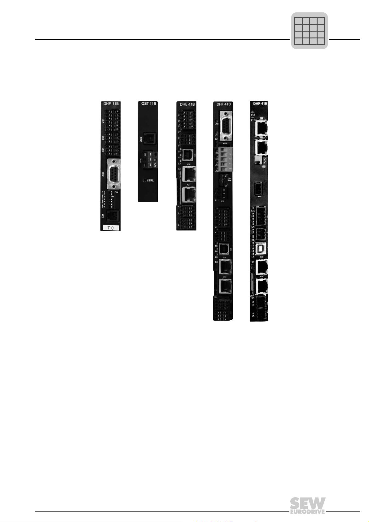
1.1.4 Control options
DHE 41B DHF 41B DHR 41BDHP 11B OST 11B
MOVI-PLC
®
P
i
f
kVA
Hz
n
P
i
f
kVA
Hz
n
System Description
System overview of MOVIDRIVE® MDX60B/61B
1
1452634507
System Manual – MOVIDRIVE® MDX60B/61B
11
1
P
i
f
kVA
Hz
n
P
i
f
kVA
Hz
n
1.1.5 Safety options
System Description
System overview of MOVIDRIVE® MDX60B/61B
DFS 11B DFS 21BDFS 12B DFS 22B
DCS 21B
DCS 31B
1452640907
12
System Manual – MOVIDRIVE® MDX60B/61B

1.1.6 General description
P
i
f
kVA
Hz
n
P
i
f
kVA
Hz
n
MOVIDRIVE
EURODRIVE. The new MOVIDRIVE
provide enhanced functions in the lower power range, more basic functions, and greater
overload capacity.
AC drives with the latest digital inverter technology can now be used without restrictions
in the 0.55 to 315 kW power range. The levels of dynamic performance and control
quality that can now be achieved with MOVIDRIVE
previously only possible using servo drives or DC motors. The integrated control functionality and the option to extend the drive using technology and communication options
creates drive systems that are designed to be particularly cost-effective with regard to
the application range, project planning, startup and operation.
1.1.7 Low-emission
The MOVIDRIVE
emission regulations, but with the usual high level of quality. One particular feature is
the consistent use of lead-free soldering materials in the production of electronics
products. These lead-free processes are in line with the RoHS EU Directive and the law
on electronic equipment.
System Description
System overview of MOVIDRIVE® MDX60B/61B
®
MDX60B/61B is the new generation of drive inverters from SEW-
®
MDX60B/61B inverters are produced according to particularly low-
®
B series inverters feature a modular design,
®
for asynchronous AC motors were
1
1.1.8 Product family
®
The MOVIDRIVE
• MOVIDRIVE® MDX60B: Drive inverter for asynchronous AC motors without encoder feed-
• MOVIDRIVE
• MOVIDRIVE
product family includes three series:
®
MDX61B: Drive inverter for asynchronous AC motors with or without
®
MDR60A: Regenerative power supply unit; MOVIDRIVE® inverters (400/
back. The units are not option-capable.
encoder feedback, or for asynchronous and synchronous servomotors. The units are option-capable.
500 V units) operate in regenerative mode to feed energy back
into the supply system.
System Manual – MOVIDRIVE® MDX60B/61B
13

1
P
i
f
kVA
Hz
n
P
i
f
kVA
Hz
n
1.1.9 Unit variants
System Description
System overview of MOVIDRIVE® MDX60B/61B
®
MOVIDRIVE
standard variant and the application variant. MOVIDRIVE
inverters are only available as application variants with coated pcbs (-0T/L).
MDX60/61B size 0-6 inverters are available in two variants, namely the
®
MDX60B/61B size 7
Standard variant The units are equipped with integrated IPOS
standard. MOVIDRIVE
"00" at the end of the type designation indicates the standard variant.
Application variant In addition to the features of the standard variant, these units include the technology
functions "electronic cam" and "internal synchronous operation". Furthermore, you can
use all the application modules available in the MOVITOOLS
ing software with the application variants.
The application variant is indicated by "0T" following the type designation.
Variants with
coated printed
circuit boards
The units are designed for use in harsh environments. The coating of the printed circuit
boards increases their resistivity against environmental conditions.
The variant with coated pcbs is indicated by "00/L" or "0T-/L" at the end of the type
designation.
®
MDX61B can be expanded with the available options.
plus®
positioning and sequence control as
®
MotionStudio engineer-
14
System Manual – MOVIDRIVE® MDX60B/61B
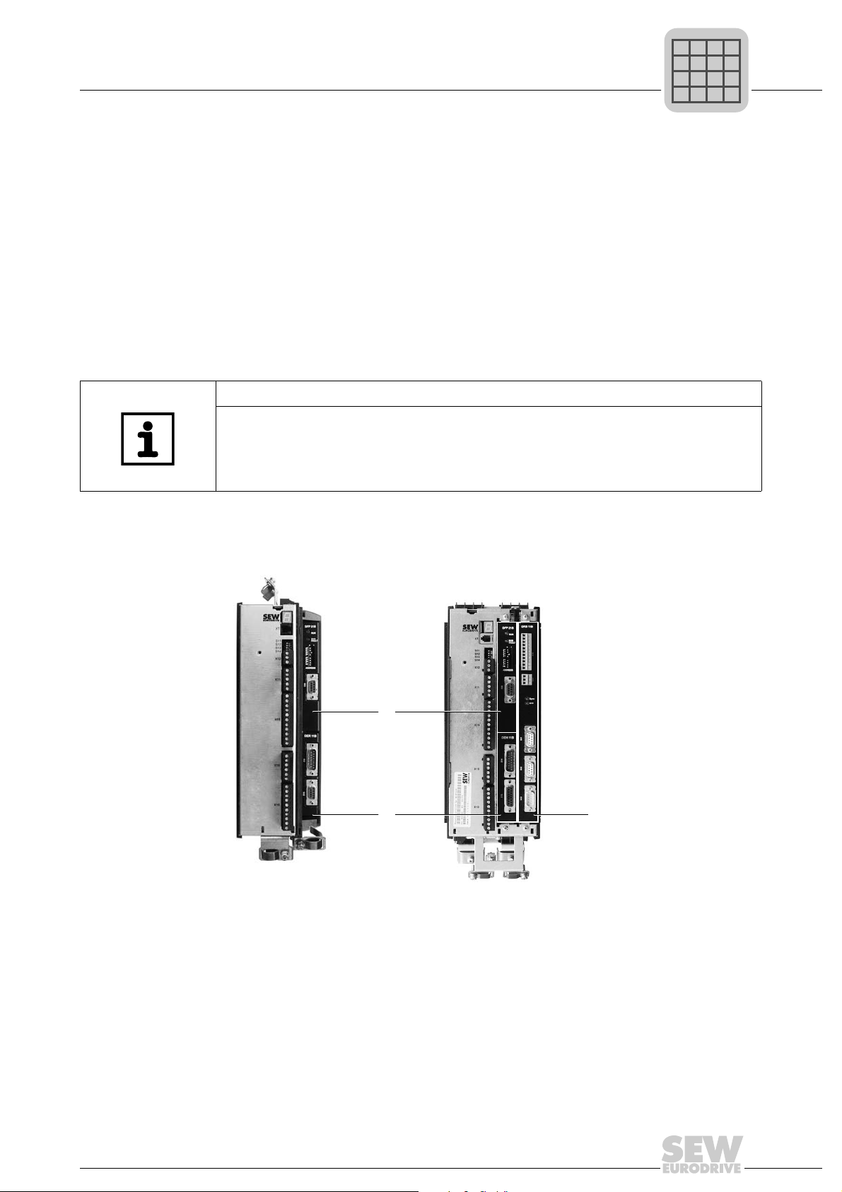
1.1.10 Modular unit concept
[2]
[1]
[3]
P
i
f
kVA
Hz
n
P
i
f
kVA
Hz
n
The option-capable MOVIDRIVE
• Size 0 (0005 ... 0014) → 2 option card slots
– 1 option card slot for encoder connection
– 1 option card slot for a communication option
• Sizes 1 ... 7 (0015 ... 2500) → 3 option card slots
– 1 option card slot for encoder connection
– 1 option card slot for a communication option
– 1 option card slot for an expansion option
INFORMATION
• Customers can only install or remove option cards later on in MDX61B sizes
1 to 7. The firmware of the option cards and the basic unit must be compatible.
•For MDX61B size 0 units, option cards can only be installed and removed later
on by SEW-EURODRIVE. Please take this aspect into account when you place
your order/perform project planning.
System Description
System overview of MOVIDRIVE® MDX60B/61B
®
MDX61B units have the following option slots:
1
1.1.11 Option card slots of MOVIDRIVE
Size 0 (0005 ... 0014) Size 1 ... 7 (0015 ... 2500)
[1] Encoder slot for encoder option
[2] Fieldbus slot for communication option
[3] Expansion slot for communication option (only sizes 1 - 7)
®
MDX61B
1806023691
System Manual – MOVIDRIVE® MDX60B/61B
The modular unit concept allows you to choose the right option according to your application. For example, when you have an asynchronous AC motor with encoder feedback
(Hiperface
DEH11B.
®
, sin/cos, or TTL), you would need the Hiperface® encoder card type option
15
1
P
i
f
kVA
Hz
n
P
i
f
kVA
Hz
n
System Description
System overview of MOVIDRIVE® MDX60B/61B
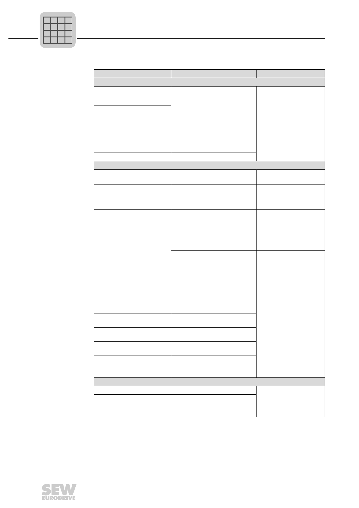
Use Required option Option card slot
Encoder option
Asynchronous AC motor with
encoder feedback (Hiperface
sin/cos, TTL)
Asynchronous or synchronous
servomotor with Hiperface®
encoder
Synchronous servomotor with
resolver
Asynchronous or synchronous
motors with absolute encoder
SSI encoder interface DEH21B absolute encoder card
Communication options (fieldbus, control)
User-programmable MOVI-PLC
controller
Additional RS485 interface (only
in combination with option
DHP11B)
Freely programmable motion and
logic controller (MOVI-PLC
Additional analog and binary
inputs/outputs are required
Integration into a PROFIBUS
system
Integration into a PROFIBUS
system with PROFIsafe
Integration into an INTERBUS
system
Integration into an Ethernet
system with PROFIsafe
Integration into an EtherCAT
system
Integration into a DeviceNet
system
Integration into a CANopen ystem CANopen interface type DFC11B
Expansion option
SSI encoder interface DIP11B absolute encoder card
Phase-synchronous operation Synchronous operation card DRS11B
Safety module DCS21B option (only in conjunction
®
,
®
Hiperface
Resolver card type DER11B
DEU21B multi-encoder card
®
MOVI-PLC®basic DHP11B controller 2
DHP11B + OST11B • DHP11B in 2, OST11B in
Controller
• DHE21B (standard)
• DHE41B (advanced)
Controller
®
• DHF21B (standard)
)
• DHF41B (advanced)
Controller
• DHR21B (standard)
• DHR41B (advanced)
Input/output card type DIO11B
PROFIBUS interface type DFP21B
DFS11B fieldbus interface
INTERBUS interface type DFI11B /
DFI21B
DFS21B fieldbus interface
®
EtherCAT
DeviceNet interface type DFD11B
with DFS12B/22B option) / DCS31B
encoder card DEH11B
®
interface type DFE24B
1
(3 only if slot 2 is occupied)
1
• If 1 is occupied:
DHP11B + OST11B in 3
2
(3 only if slot 2 is occupied)
3
3
2
(3 only if slot 2 is occupied)
2
3
16
System Manual – MOVIDRIVE® MDX60B/61B

1.1.12 Control modes
P
i
f
kVA
Hz
n
P
i
f
kVA
Hz
n
System Description
System overview of MOVIDRIVE® MDX60B/61B
1
The VFC (Voltage Mode Flux Control) and CFC (Current Mode Flux Control)/SERVO
control modes are features of MOVIDRIVE
calculation of the complete motor model forms the basis for both control modes.
VFC control mode
(Voltage Mode Flux Control)
Voltage-controlled control mode for asynchronous
AC motors with and without encoder feedback.
• With encoder feedback
– At least 150% torque, with a power-
– Characteristics similar to servo operation
• Without encoder feedback
– min. 150% torque up to 0.5 Hz, with a
1.1.13 System bus (SBus)
The system bus (SBus), which is installed as standard, allows several MOVIDRIVE
inverters to be networked together. This system bus enables fast data exchange
between the units. The MOVILINK
MOVILINK
SBus can be switched to CANopen.
1.1.14 MOVILINK
®
MOVILINK® always uses the same message format independent of the selected interface (SBus, RS232, RS485, fieldbus interfaces). As a result, the control software is
independent of the selected interface.
®
MDX60B/61B inverters. The continuous
Control modes
CFC (Current Mode Flux Control)/SERVO
Current-controlled control mode for asynchronous
and synchronous servomotors. Encoder feedback is
always required.
matched, stopped motor
power-matched motor
®
®
is the universal SEW-EURODRIVE standard for serial communication. The
unit profile is used for communication via the SBus.
• At least 160% torque, with a power-matched,
stopped motor
• Maximum precision and concentric running
characteristics right down to standstill.
• Servo characteristics and torque control even
for asynchronous AC motors
• Reacts to load changes within a few milliseconds
®
1.1.15 IPOS
plus®
A significant feature of MOVIDRIVE® inverters is that the IPOS
sequence control system is integrated as standard. IPOS
plus®
plus®
positioning and
enables you to control
motion sequences directly in the inverter close to the machine. This way, load is taken
off the higher-level controller and modular concepts can be implemented more easily.
System Manual – MOVIDRIVE® MDX60B/61B
17
1
P
i
f
kVA
Hz
n
P
i
f
kVA
Hz
n
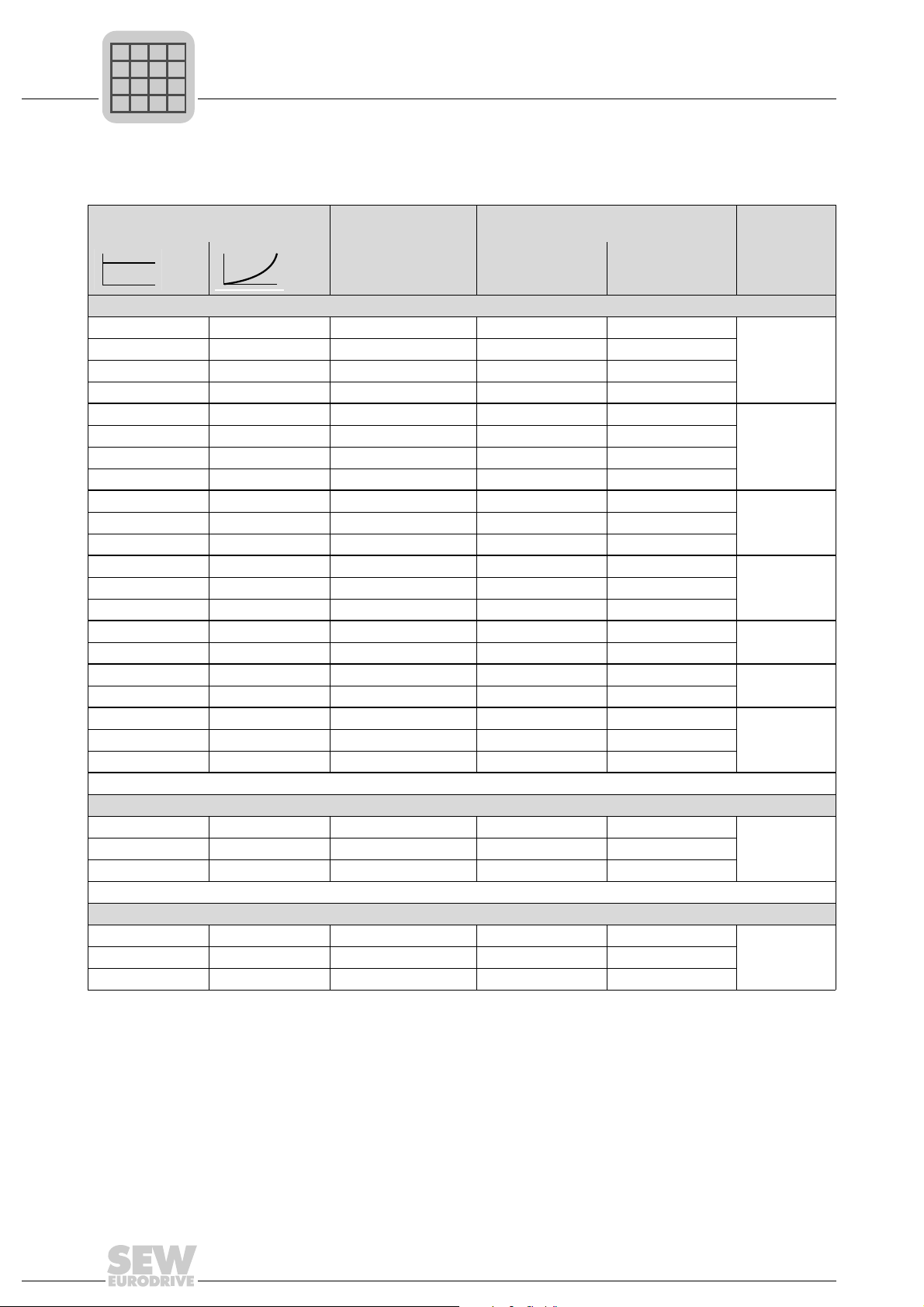
1.1.16 Overview of the units
MOVIDRIVE
®
MDX60/61B for 3 × AC 380 ... 500 V supply voltage (400/500 V units):
System Description
System overview of MOVIDRIVE® MDX60B/61B
Recommended motor power (VFC)
4Q units (with brake chopper)
0.55 kW (0.74 HP) 0.75 kW (1.0 HP) AC 2.0 A 0005-5A3-4-.. 0005-5A3-4-..
0.75 kW (1.0 HP) 1.1 kW (1.5 HP) AC 2.4 A 0008-5A3-4-.. 0008-5A3-4-..
1.1 kW (1.5 HP) 1.5 kW (2.0 HP) AC 3.1 A 0011-5A3-4-.. 0011-5A3-4-..
1.5 kW (2.0 HP) 2.2 kW (3.0 HP) AC 4.0 A 0014-5A3-4-.. 0014-5A3-4-..
1.5 kW (2.0 HP) 2.2 kW (3.0 HP) AC 4.0 A - 0015-5A3-4-..
2.2 kW (3.0 HP) 3.0 kW (4.0 HP) AC 5.5 A - 0022-5A3-4-..
3.0 kW (4.0 HP) 4.0 kW (5.4 HP) AC 7.0 A - 0030-5A3-4-..
4.0 kW (5.4 HP) 5.5 kW (7.4 HP) AC 9.5 A - 0040-5A3-4-..
5.5 kW (7.4 HP) 7.5 kW (10 HP) AC 12.5 A - 0055-5A3-4-..
7.5 kW (10 HP) 11 kW (15 HP) AC 16 A - 0075-5A3-4-..
11 kW (15 HP) 15 kW (20 HP) AC 24 A - 0110-5A3-4-..
15 kW (20 HP) 22 kW (30 HP) AC 32 A - 0150-503-4-..
22 kW (30 HP) 30 kW (40 HP) AC 46 A - 0220-503-4-..
30 kW (40 HP) 37 kW (50 HP) AC 60 A - 0300-503-4-..
37 kW (50 HP) 45 kW (60 HP) AC 73 A - 0370-503-4-..
45 kW (60 HP) 55 kW (74 HP) AC 89 A - 0450-503-4-..
55 kW (74 HP) 75 kW (100 HP) AC 105 A - 0550-503-4-..
75 kW (100 HP) 90 kW (120 HP) AC 130 A - 0750-503-4-..
90 kW (120 HP) 110 kW 148 HP) AC 170 A - 0900-503-4-..
110 kW (148 HP) 132 kW (177 HP) AC 200 A - 1100-503-4-..
132 kW (177 HP) 160 kW (215 HP) AC 250 A - 1320-503-4-..
-
2Q units (without brake chopper)
160 kW (215 HP) 200 kW (268 HP) AC 300 A - 1600-503-2-0T/L
200 kW (268 HP) 250 kW (335 HP) AC 380 A - 2000-503-2-0T/L
250 kW (335 HP) 315 kW (422 HP) AC 470 A - 2500-503-2-0T/L
Continuous output
current
(CFC)
MOVIDRIVE® type Size
MDX60B
not option-capable
MDX61B
option-capable
(techn.
data)
0
(page 42)
1
(page 44)
2S, 2
(page 45)
3
(page 46)
4
(page 47)
5
(page 48)
6
(page 49)
7
(page 50)
4Q units (with brake chopper)
160 kW (215 HP) 200 kW (268 HP) AC 300 A - 1600-503-4-0T/L
200 kW (268 HP) 250 kW (335 HP) AC 380 A - 2000-503-4-0T/L
250 kW (335 HP) 315 kW (422 HP) AC 470 A - 2500-503-4-0T/L
18
System Manual – MOVIDRIVE® MDX60B/61B
7
(page 50)
System Description
P
i
f
kVA
Hz
n
P
i
f
kVA
Hz
n
System overview of MOVIDRIVE® MDX60B/61B
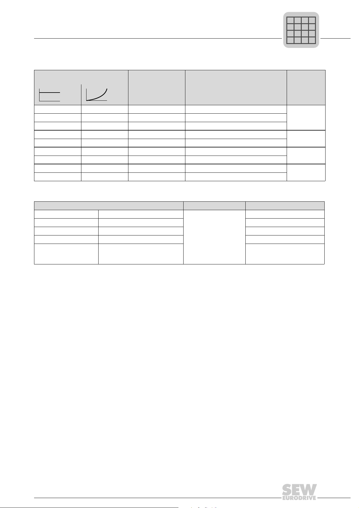
MOVIDRIVE® MDX60/61B for 3 × AC 200 ... 240 V supply voltage (230 V units):
1
Recommended motor power (VFC)
1.5 kW (2.0 HP) 2.2 kW (3.0 HP) AC 7.3 A 0015-2A3-4-..
2.2 kW (3.0 HP) 3.7 kW (5.0 HP) AC 8.6 A 0022-2A3-4-..
3.7 kW (5.0 HP) 5.0 kW (7.0 HP) AC 14.5 A 0037-2A3-4-..
5.5 kW (7.4 HP) 7.5 kW (10 HP) AC 22 A 0055-2A3-4-..
7.5 kW (10 HP) 11 kW (15 HP) AC 29 A 0075-2A3-4-..
11 kW (15 HP) 15 kW (20 HP) AC 42 A 0110-203-4-..
15 kW (20 HP) 22 kW (30 HP) AC 54 A 0150-203-4-..
22 kW (30 HP) 30 kW (40 HP) AC 80 A 0220-203-4-..
30 kW (40 HP) 37 kW (50 HP) AC 95 A 0300-203-4-..
®
MOVIDRIVE
MOVIDRIVE® MDR60A regenerative power supply units Size (technical data) MOVIDRIVE®MDX60B/61B...-5_3
0150-503-01 I
0370-503-00 I
0750-503-00 I
1320-503-00 I
1320-503-00
As of series no.
DCV2000100
MDR60A regenerative power supply units for 400/500 V units:
= AC 29 A, I
line
= AC 66 A, I
line
= AC 117 A, I
line
= AC 225 A, I
line
I
= AC 260 A, I
line
Continuous output
current
(CFC)
= DC 35 A
DC link
= DC 70 A 0005 ... 0370
DC link
= DC 141 A 0005 ... 0750
DC link
= DC 270 A 0005 ... 1320
DC link
= DC 324 A 0005 ... 1600
DC link
3, 4, 6
(page 76)
MOVIDRIVE® type Size
MDX61B
option-capable
(technical
data)
1
(page 51)
2
(page 52)
3
(page 53)
4
(page 54)
0005 ... 0150
System Manual – MOVIDRIVE® MDX60B/61B
19
1
P
i
f
kVA
Hz
n
P
i
f
kVA
Hz
n
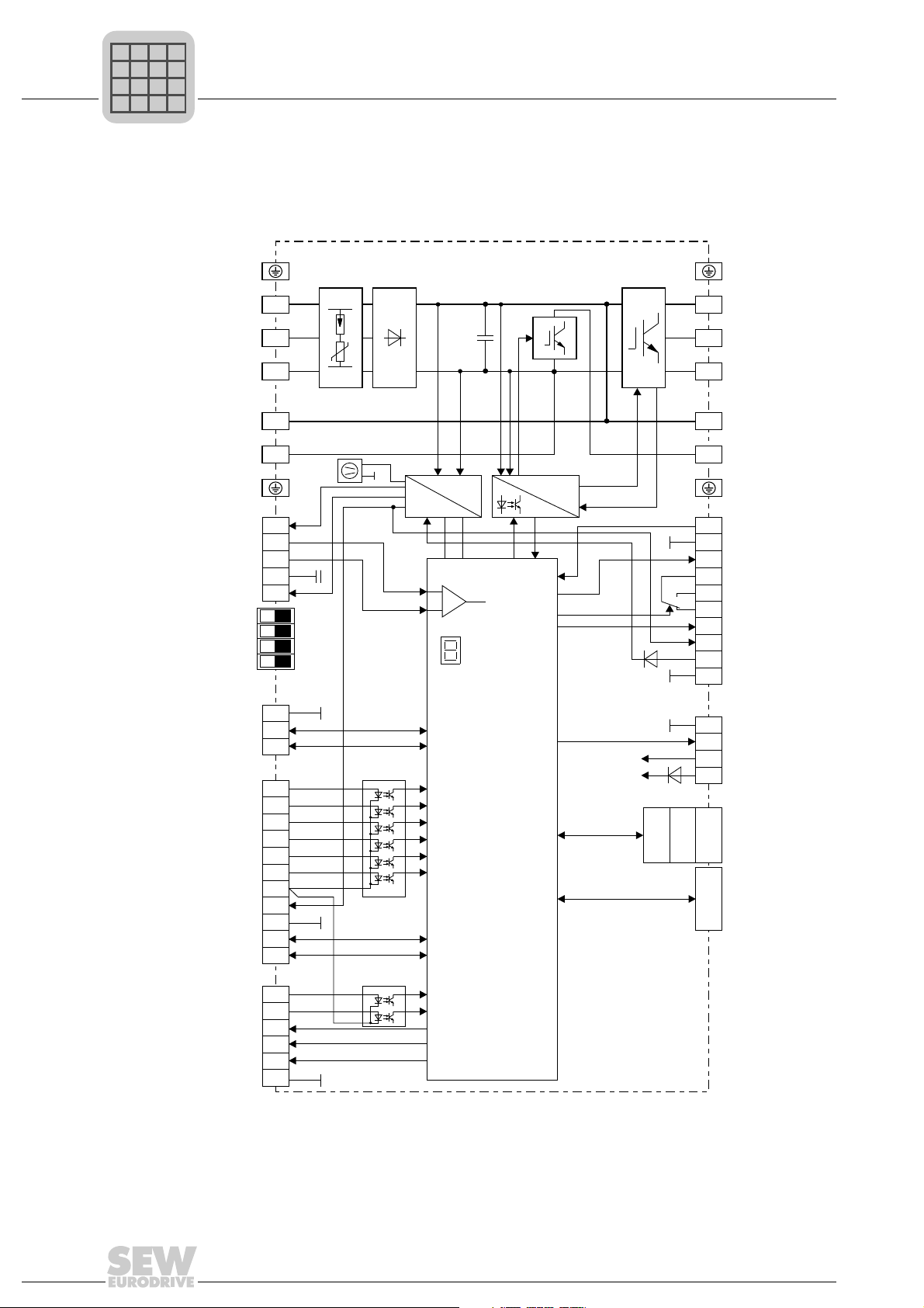
1.1.17 Block circuit diagram
System Description
System overview of MOVIDRIVE® MDX60B/61B
Power
supply
Analog input
and reference
voltages
AGND
I-Signal U-Signal
Terminating resistor SBus
Frequency input active
RS485 baud rate
GND
System bus
Potential-free
binary inputs
Reference
DC+24 V output
RS485
interface
Potential-free
binary inputs
Binary outputs
The following block circuit diagram shows the basic structure and theory of operation of
®
MOVIDRIVE
PE
1
L1
L2
2 5
L3
3
DC link
connection
8 8
7
1
2
3
4
5
ON OFF
1
2
3
1
2
3
4
5
6
7
8
9
10
11
1
2
3
4
5
6
MDX60B/61B inverters.
Input
X1:
protection
circuit
X4:
Fan
X11:
S11
S12
S13
S14
X12:
X13:
X16:
DC link Brake
Power supply
unit
Control unit
+
-
7-segment
display
Micro processor
X2:
chopper
BRC
ON
U
Z
InverterRectifier
Control
signals
Current
measurement
X3:
X10:
X17:
OPTION2
OPTION1
PE
4
U
V
W
6
Braking resistor
connection
9
1
TF/TH/KTY input
2
GND
3
Binary output
4
5
Relay output
6
7
Binary output
8
DC+24 V output
9
DC+24 V input
GND
10
1
2
STO
3
4
OPTION3 Xterminal
Option
slots
(not in MDX60B)
Keypad
or
interface
adapter
Motor
1452719115
20
System Manual – MOVIDRIVE® MDX60B/61B

1.2 Functions/features
P
i
f
kVA
Hz
n
P
i
f
kVA
Hz
n
1.2.1 Unit features
• Wide voltage range
– 400/500 V units for the voltage range 3 × AC 380 ... 500 V
– 230 V units for the voltage range 3 × AC 200 ... 240 V
• High overload capacity
– Size 0: 200% I
– Sizes 1 ... 6: 150% I
– All sizes: 125% I
• Sizes 0 ... 6:
– With 4 kHz switching frequency, I
ϑ =50°C
– 4Q capability due to integrated brake chopper installed as standard
•Size 7:
– With 2.5 kHz switching frequency, I
ϑ =50°C
System Description
Functions/features
for at least 60 s
N
for at least 60 s
N
, continuous operation without overload (pumps, fans)
N
is permitted for an ambient temperature of
N
is permitted for an ambient temperature of
N
1
• Compact unit design for minimum control cabinet space requirement and optimum
• Integrated input filter fitted as standard in sizes 0, 1, 2S and 2, adherence to class
• 8 isolated binary inputs and 6 binary outputs, one of which is a relay output; program-
• 1 TF/TH/KTY input for motor protection using a PTC thermistor or thermocontact
• 7-segment display for operating and fault states
• Separate DC 24 V voltage input for powering the inverter electronics (parameter
• Separable electronic terminals
• Separable power terminals for size 0 and 1 units
• STO in accordance with EN 61800-5-2, up to
1.2.2 Control functions
• VFC or CFC control modes for field-oriented operation (asynchronous servo)
•IPOS
• Two complete parameter sets
• Automatic motor calibration
– 2Q units without brake chopper or 4Q units with brake chopper can be selected
utilization of control cabinet volume
C2 limit on the input side without any additional measures
mable inputs/outputs
setting, diagnostics and data storage even when the supply system is switched off)
– Category 3 according to EN 954-1
– Performance level d according to EN ISO 13849-1
plus®
positioning and sequence control system integrated as standard
• Automatic brake control by the inverter
• DC braking to decelerate the motor even in 1Q mode
• Energy-saving function for optimizing the magnetization current automatically
System Manual – MOVIDRIVE® MDX60B/61B
21

1
P
i
f
kVA
Hz
n
P
i
f
kVA
Hz
n
System Description
Functions/features
• Slip compensation for high stationary speed accuracy, even without encoder
feedback
• Flying restart function for synchronizing the inverter to an already rotating SEW
motor
• Hoist capability with all motor systems that can be connected
• Motor stall protection through sliding current limitation in the field weakening range
• Function to hide speed window to avoid mechanical resonances
• Heating current to avoid condensation build-up in the motor
• Parameter lock for protection against changes to parameters
®
• Speed controller and encoder input for incremental, Hiperface
resolvers. User-friendly controller setting tool in the operator interface.
• Protective functions for complete protection of the inverter and motor (short-circuit,
overload, overvoltage/undervoltage, ground fault, excess temperature in the inverter,
motor stall prevention, excess temperature in the motor)
• Speed monitoring and monitoring of the motor and regenerative limit power
or SSI encoders and
• Programmable signal range monitoring (speed, current, maximum current)
• Memory for displaying X/t diagrams using SCOPE process data visualization
(8 channels, real-time capable)
• Fault memory (5 memory locations) with all relevant operating data at the time of the
fault
• Operating hours counter for hours of operation (unit connected to supply system or
DC 24 V) and enable hours (output stage energized)
• Modular option technology for application-specific unit configuration
• Uniform operation, identical parameter setting and the same unit connection technology for the entire MOVIDRIVE
1.2.3 Setpoint technology
• Ramp switchover (total of 4 ramps)
• Motor potentiometer, can be combined with analog setpoint and internal fixed
setpoints
• External setpoint selections: DC (0 ... +10 V, -10 V ... +10 V, 0 ... 20 mA, 4 ... 20 mA)
• S pattern for jerk-free speed changes
• Programmable input characteristic curve for flexible setpoint processing
• 6 bipolar fixed setpoints which can be mixed with external setpoints and motor
potentiometer function
• Primary frequency input
®
unit series
• Adjustable jerk limitation
1.2.4 Communication/operation
®
• System bus for networking max. 64 MOVIDRIVE
• RS485 interface for communication between one PLC/IPC and up to 31 inverters
• Simple startup and parameter setting using a keypad or PC
• Pluggable memory module for quick unit replacement during service
22
System Manual – MOVIDRIVE® MDX60B/61B
units to one another

1.2.5 System expansion
P
i
f
kVA
Hz
n
P
i
f
kVA
Hz
n
• Extensive expansion options, for example:
– Removable plain text keypad with parameter memory
– USB11A, RS232 ↔ RS485 interface adapter
– Fieldbus interface, either PROFIBUS, INTERBUS, Ethernet, DeviceNet, CAN/
– Input/output card
– Braking resistors, line filters, line chokes, output chokes, output filters
• MOVITOOLS
• Application version with access to technology functions and application modules to
solve drive tasks quickly and easily
•MOVIDRIVE
back into the supply system, which removes the thermal load from the control cabinet
and saves costs.
CANopen
System Description
Functions/features
®
MotionStudio with SCOPE process data visualization
®
MDR60A regenerative power supply unit. Regenerative energy is fed
1
1.2.6 Standards and approvals
• UL, cUL, C-Tick approval. The MOVIDRIVE
have UL or cUL or C-Tick approval. The GOST-R certificate (Russia) has been
approved for the MOVIDRIVE
• Safe disconnection of power and electronic connections according to EN 61800-5-1
• Compliance with all the requirements for CE certification of machines and plants
equipped with MOVIDRIVE
and the EMC Directive 2004/108/EC. Complies with the EMC product standard
EN 61800-3.
• STO in accordance with EN 61800-5-2, up to
– Category 3 according to EN 954-1
– Performance level d according to EN ISO 13849-1
®
MDR60A1320-503-00 unit does not
®
range of units.
®
on the basis of the Low Voltage Directive 2006/95/EC
System Manual – MOVIDRIVE® MDX60B/61B
23

1
MASTER
SLAVE
P
i
f
kVA
Hz
n
P
i
f
kVA
Hz
n
System Description
Additional functions of the application variants
1.3 Additional functions of the application variants
1.3.1 Electronic cam
SEW-EURODRIVE offers additional functions for special applications. You can use
these additional functions with the MOVIDRIVE
The following additional functions are available:
• Electronic cam
• Internal synchronous operation
®
application variants (...-0T).
INFORMATION
Please refer to the "Electronic Cam" and "Internal Synchronous Operation" manuals for
detailed information about the additional functions.
®
You can use the MOVIDRIVE
ever you need to harmonize complex sequences of motion in cyclical machines. This
solution gives you much greater flexibility in comparison to the mechanical cam. As a
result, it meets the needs of modern production and processing lines.
A user-friendly cam editor supports you during startup. You also have the option of
importing existing cam data. You can also set application-specific parameters for the
engagement and disengagement phases using the cam editor.
product series with the "electronic cam" module when-
Note the following points:
®
• The "electronic cam" can only be implemented with the MOVIDRIVE
application version (...-0T).
• Encoder feedback is mandatory. This is why the "electronic cam" can only be
realized in "CFC", "SERVO" and "VFC-n control" operating modes with master/slave
connection via X14-X14 or with an SBus connection.
• "Electronic cam" is only available in parameter set 1.
• The "DRS11B synchronous operation card" option cannot be used together with the
"electronic cam" function.
MDX61B
24
System Manual – MOVIDRIVE® MDX60B/61B
System Description
P
i
f
kVA
Hz
n
P
i
f
kVA
Hz
n
Additional functions of the application variants
1
Motors and
encoders
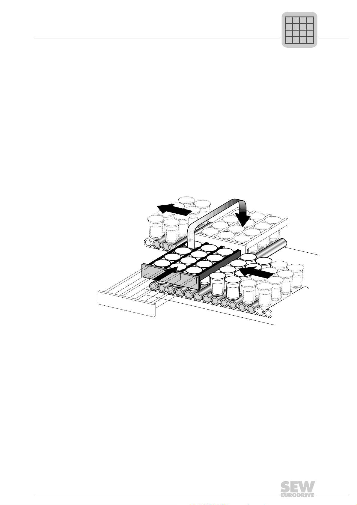
Example The figure below shows a typical application example for the "electronic cam." Filled
Use the following motor types:
®
• For operation with MOVIDRIVE
– CT/CV asynchronous servomotor, high-resolution sin/cos encoder installed as
standard or Hiperface
– DT/DV/D series AC motor with incremental encoder, preferably high-resolution
sin/cos encoder or Hiperface
– Synchronous servomotors DS/CM/CMD/CMP, resolver (installed as standard) or
Hiperface
High-resolution speed measurement is required for optimum operation of the electronic
cam. The encoders installed as standard on CT/CV and DS/CM/CMD/CMP motors fulfill
these requirements. SEW-EURODRIVE recommends using high-resolution sin/cos
encoders as incremental encoders if DR/DT/DV/D motors are used.
yogurt pots are transported for further processing. The "electronic cam" enables smooth
movement, which is an important requirement for this application.
®
encoder
®
MDX61B...-4-0T:
encoder.
®
encoder.
1453201035
System Manual – MOVIDRIVE® MDX60B/61B
25

1
P
i
f
kVA
Hz
n
P
i
f
kVA
Hz
n
1.3.2 Internal synchronous operation
Motors and
encoders
System Description
Additional functions of the application variants
You can use the MOVIDRIVE
ever a group of motors has to be operated at a synchronous angle in relation to one
another or with an adjustable proportional ratio (electronic gear). A user-friendly editor
guides you through the startup procedure.
Note the following points:
• "Internal synchronous operation" can only be implemented with MOVIDRIVE
MDX61B application versions (...-0T).
• Encoder feedback is mandatory. This is why "internal synchronization operation" can
only be realized in "CFC", "SERVO" and "VFC-n control" operating modes with
master/slave connection via X14-X14 or with an SBus connection.
• "Internal synchronous operation" is only available in parameter set 1.
• The "DRS11B synchronous operation card" option cannot be used together with
"internal synchronous operation".
Use the following motor types for operation with MOVIDRIVE
• CT/CV asynchronous servomotor, high-resolution sin/cos encoder installed as
standard or Hiperface
• DT/DV/D series AC motor with incremental encoder, preferably high-resolution sin/
cos encoder or Hiperface
• Synchronous servomotors DS/CM/CMD/CMP, resolver (installed as standard) or
Hiperface
®
encoder
®
unit series with "internal synchronous operation" when-
®
MDX61B...-4-0T:
®
encoder.
®
encoder.
®
High-resolution speed measurement is required for optimum "internal synchronous
operation". The encoders installed as standard on CT/CV and DS/CM/CMD/CMP
motors fulfill these requirements. SEW-EURODRIVE recommends using highresolution sin/cos encoders as incremental encoders if DR/DT/DV/D motors are used.
26
System Manual – MOVIDRIVE® MDX60B/61B
System Description
P
i
f
kVA
Hz
n
P
i
f
kVA
Hz
n
Additional functions of the application variants
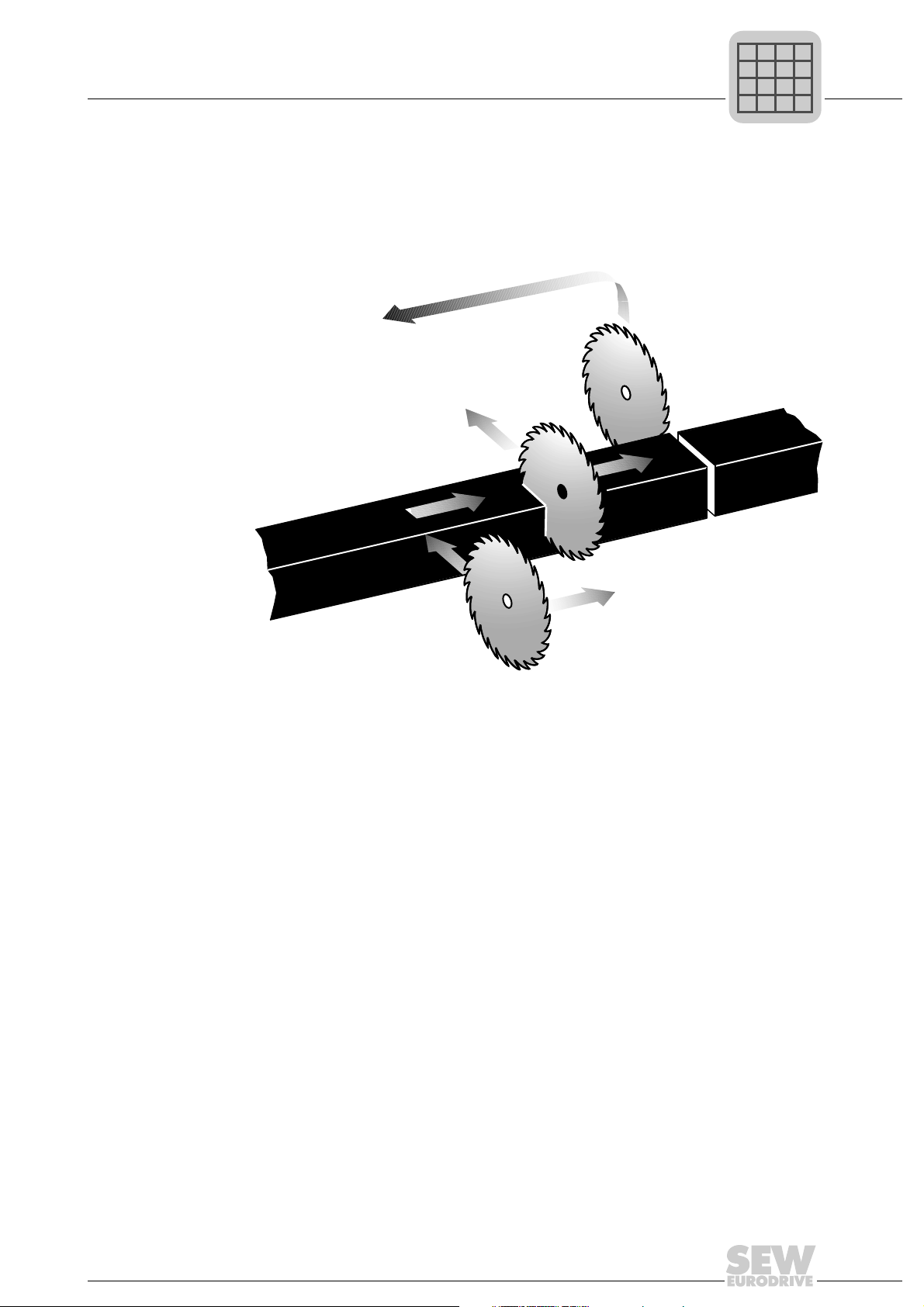
Example The figure below shows a typical application with "internal synchronous operation".
Extruder material must be cut to length. The saw receives a start signal and synchronizes with the material. During the sawing process, the saw moves synchronously with
the material. At the end of the sawing process the saw moves back to its starting
position.
1
41692939
System Manual – MOVIDRIVE® MDX60B/61B
27

1
P
i
f
kVA
Hz
n
P
i
f
kVA
Hz
n
System Description
Application modules for MOVIDRIVE® MDX61B
1.4 Application modules for MOVIDRIVE® MDX61B
1.4.1 The drive task
The drive task often involves more than just adjusting the speed of a motor. The inverter
often has to control motion sequences and take on typical PLC tasks. Increasingly
complex drive applications have to be solved, without this resulting in lengthy configuration and startup processes.
1.4.2 The solution with MOVIDRIVE
SEW-EURODRIVE offers various standardized control programs specifically for
"positioning," "winding," and "controlling" applications. These programs are called
application modules. The application modules are incorporated into MOVITOOLS
MotionStudio and can be used with the application variants.
A user-friendly operator interface guides you through the process of setting the
parameters. All you have to do is enter the parameters you need for your application.
The application module uses this information to create the control program and loads it
into the inverter. MOVIDRIVE
load is taken off the machine control and decentralized concepts are easier to implement.
The advantages at
a glance
• A wide range of functions
• A user-friendly GUI
• You only have to enter the parameters needed for the application
• Guided parameter setting process instead of complicated programming
• No programming experience required
• No lengthy training, therefore quick project planning and startup
• All movements are controlled directly in MOVIDRIVE
• Decentralized concepts can be implemented more easily
®
®
®
takes over complete control of the motion processes, the
®
1.4.3 Scope of delivery and documentation
®
The application modules are part of the MOVITOOLS
software and can be used with MOVIDRIVE
individual application manuals can also be downloaded as PDFs from the SEW website.
28
®
MDX61B application versions (...-0T). The
System Manual – MOVIDRIVE® MDX60B/61B
MotionStudio engineering

System Description
P
i
f
kVA
Hz
n
P
i
f
kVA
Hz
n
Application modules for MOVIDRIVE® MDX61B
1.4.4 Available application modules
The application modules currently available are listed below. These application modules
are explained on the following pages.
Positioning Linear movement; the inverter manages the movement records:
• Table positioning via terminal or fieldbus
Linear movement; the PLC manages the movement records:
• Bus positioning
• Extended positioning via bus
• Absolute positioning (rapid/creep speed positioning)
Rotary movement:
• Module positioning via terminals: The inverter manages the movement records
• Module positioning via fieldbus: The PLC manages the movement records
Winding • Center winder
1
Control • Flying saw
• DriveSync via fieldbus
• Sensor-based positioning
System Manual – MOVIDRIVE® MDX60B/61B
29
1
1.
2.
3.
P
i
f
kVA
Hz
n
P
i
f
kVA
Hz
n
1.4.5 Application
System Description
Application modules for MOVIDRIVE® MDX61B
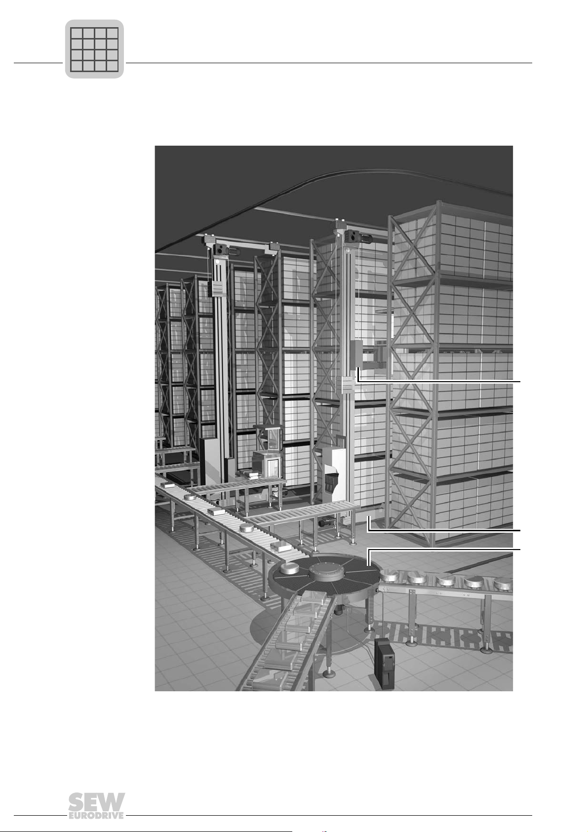
The following figure shows an example of how the various SEW application modules are
used in a block warehouse.
1. Hoist: Table positioning
2. Travel axis: Absolute or bus positioning
3. Rotary distributor: Modulo positioning
30
System Manual – MOVIDRIVE® MDX60B/61B
1453256971
 Loading...