

SEW movidrive md_60a User Manual

MOVIDRIVE® MD_60A
Edition
Absolute Positioning
03/2001
Manual
1051 0117 / EN

SEW-EURODRIVE

1 Important Notes...................................................................................................... 4
2 System Description................................................................................................ 5
2.1 Application fields............................................................................................ 5
2.2 Application examples..................................................................................... 6
3 Project Planning.....................................................................................................7
3.1 Pre-requisites.................................................................................................7
3.2 Functional description.................................................................................... 8
3.3 Scaling of the drive ........................................................................................ 9
3.4 Limit switches and machine zero................................................................. 10
3.5 Process data assignment............................................................................. 11
4 Installation ............................................................................................................ 13
4.1 Software.......................................................................................................13
4.2 Basic unit with "absolute encoder interface type DIP11A" option................ 14
4.3 Bus installation.............................................................................................15
4.4 Connecting the limit switches....................................................................... 24
I
00
5 Startup................................................................................................................... 25
5.1 General information ..................................................................................... 25
5.2 Preliminary work........................................................................................... 25
5.3 Starting the "absolute positioning" program.................................................26
5.4 Parameters .................................................................................................. 31
5.5 Starting the drive..........................................................................................32
6 Operation and Service......................................................................................... 35
6.1 Timing diagrams........................................................................................... 35
6.2 Error information .......................................................................................... 38
6.3 Error messages............................................................................................ 39
MOVIDRIVE® MD_60A, Absolute Positioning
3
®
Documentation
Safety and
warning
instructions
®
® ®
→ →
4
MOVIDRIVE® MD_60A, Absolute Positioning
2.1 Application fields
®
MOVIDRIVE® MD_60A, Absolute Positioning
18
®
•
5
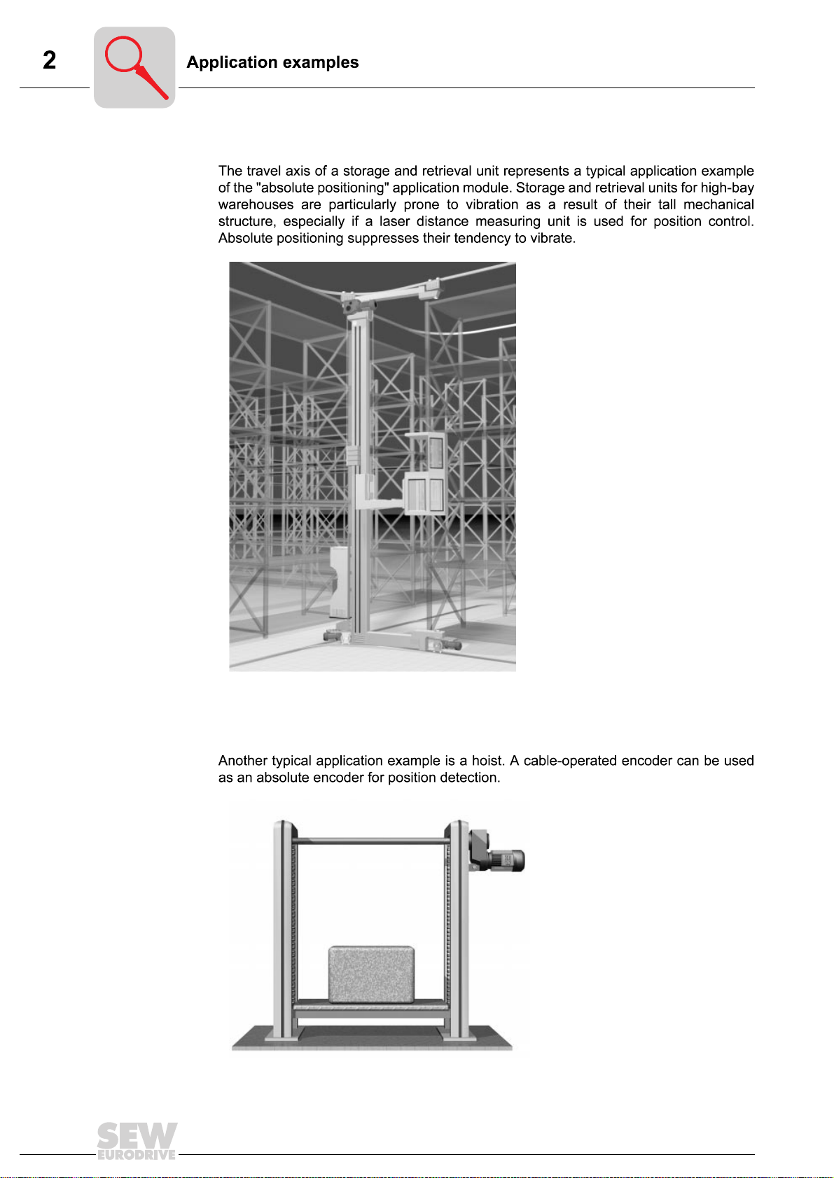
2.2 Application examples
Storage and
retrieval unit for
high-bay
warehouse
Hoist
Fig. 1: Application example of a storage and
04430AXX
retrieval unit for high-bay warehouse
00786AXX
Fig. 2: Application example of a hoist
6
MOVIDRIVE® MD_60A, Absolute Positioning
3.1 Pre-requisites
PC and software
plus®
® ®
®
Licence
Inverters, motors
and encoders
®
®
®
®
®
®
®
®
®
®
→
®
MOVIDRIVE® MD_60A, Absolute Positioning
7
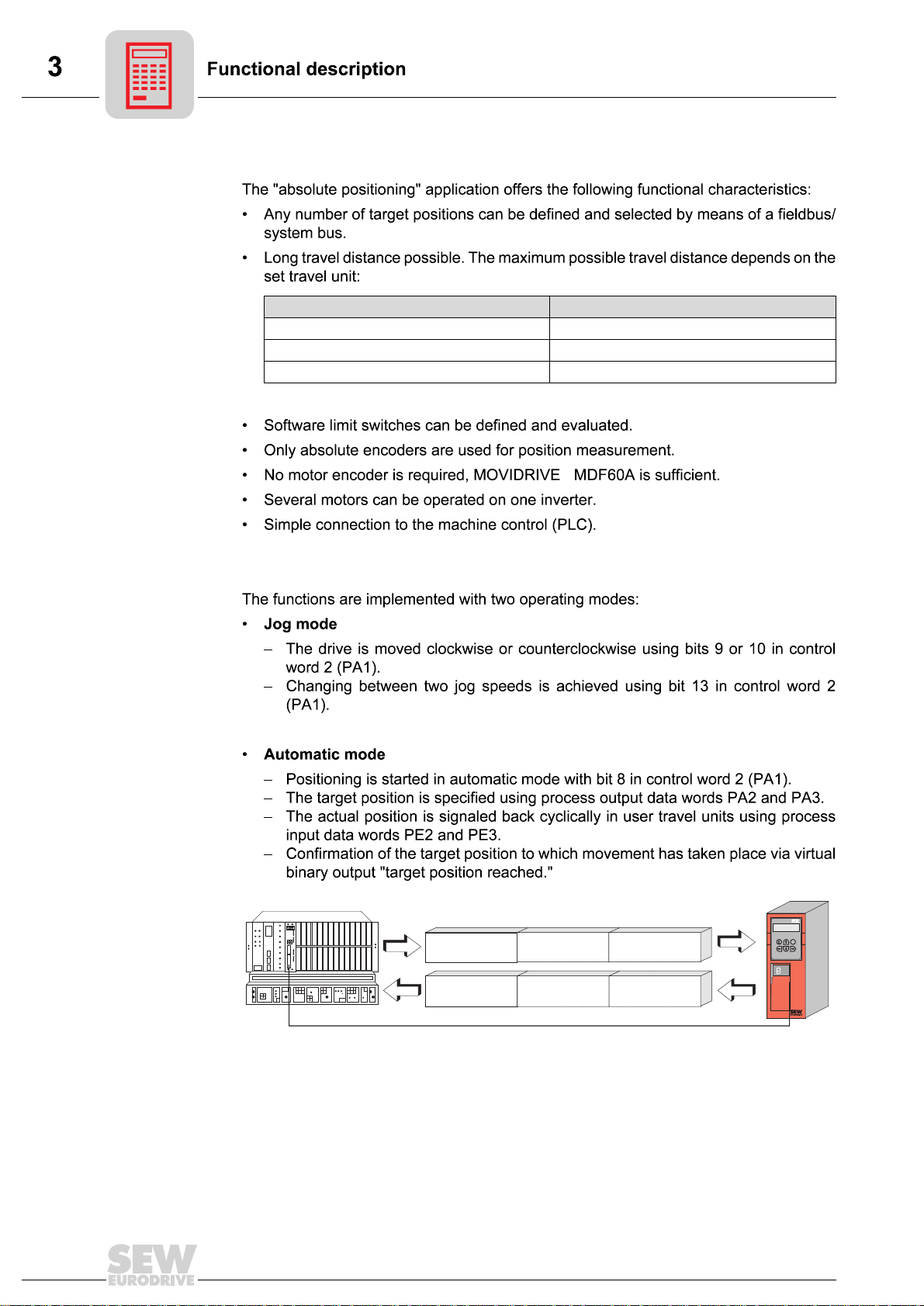
3.2 Functional description
Functional
characteristics
Travel unit Maximum possible travel distance
1/10 mm 26.2144 m
mm 262.144 m
m 262 144 m
Operating modes
®
PA
Q
Q
PA1
PE1
PA2
PE2
PA3
PE3
E
PE
Fig. 3: Data exchange via process data
04427AXX
PA = Process output data PE = Process input data
PA1 = Control word PE1 = Status word
PA2 = Target position high PE2 = Actual position high
PA3 = Target position low PE3 = Actual position low
8
MOVIDRIVE® MD_60A, Absolute Positioning
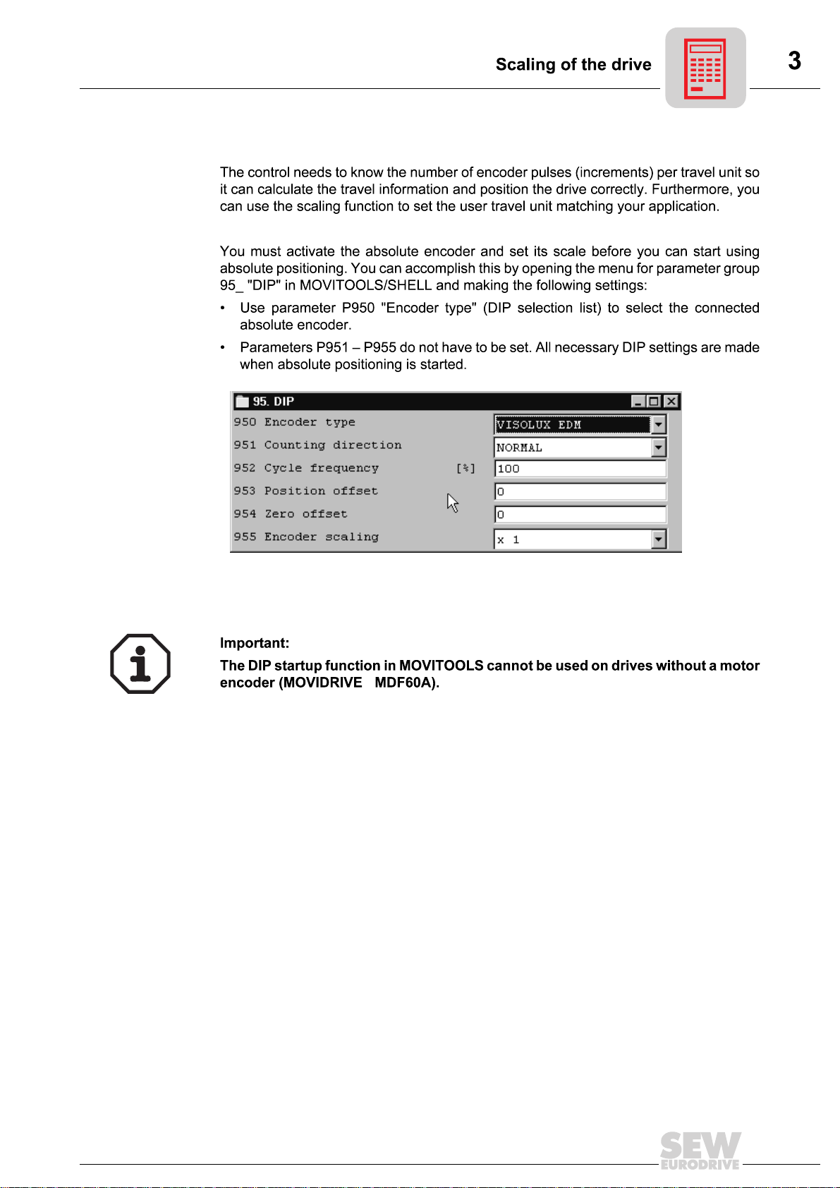
3.3 Scaling of the drive
Activating the
absolute encoder
Fig. 4: Activating the absolute encoder
®
04429AEN
MOVIDRIVE® MD_60A, Absolute Positioning
9
3.4 Limit switches and machine zero
Machine zero
Software limit
switches
→
10
MOVIDRIVE® MD_60A, Absolute Positioning
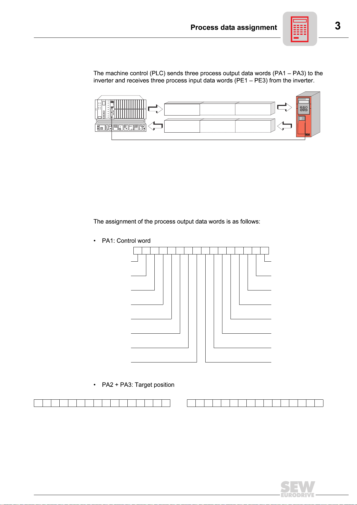
3.5 Process data assignment
PA1
PA
PA2
PA3
Q
Q
E
Process output
data
PE1
PE2
PE3
PE
Fig. 5: Data exchange via process data
04427AXX
PA = Process output data PE = Process input data
PA1 = Control word PE1 = Status word
PA2 = Target position high PE2 = Actual position high
PA3 = Target position low PE3 = Actual position low
15 14 13 12 11 10 9 8 7 6 5 4 3 2 1 0
Reserved
Ramp selection Enable/rapid stop
Speed selection Enable/stop
Controller inhibit/
enable
Mode select
high
Mode select low Reserved
Jog - Reserved
Jog + Error reset
Start Reserved
PA2 Target position high PA3 Target position low
1514131211109876543210 1514131211109876543210
Target position [user travel unit]
Reserved
MOVIDRIVE® MD_60A, Absolute Positioning
11
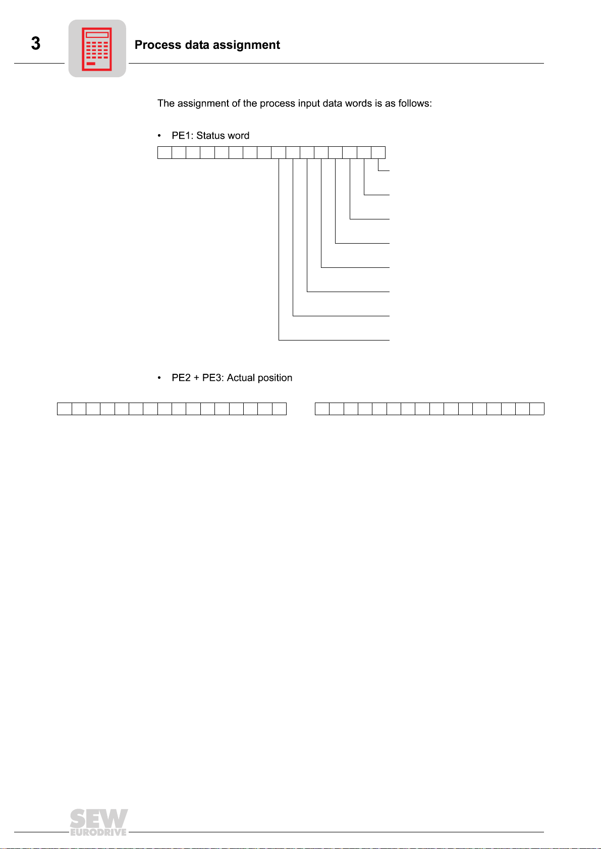
Process input
data
15 14 13 12 11 10 9 8 7 6 5 4 3 2 1 0
Inverter status/fault code
PE2 Actual position high PE3 Actual position low
1514131211109876543210 1514131211109876543210
Actual position [user travel unit]
Motor turning (n ≠ 0)
Inverter ready
IPOS reference (= drive referenced)
Target position reached
Brake released
Fault/warning
CW limit switch
CCW limit switch
12
MOVIDRIVE® MD_60A, Absolute Positioning
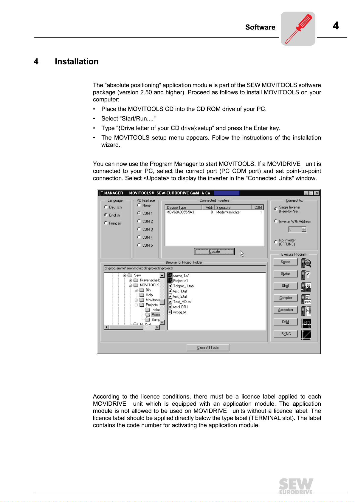
4.1 Software
MOVITOOLS
®
Fig. 6: MOVITOOLS window
Licence
MOVIDRIVE® MD_60A, Absolute Positioning
®
04431AEN
®
13
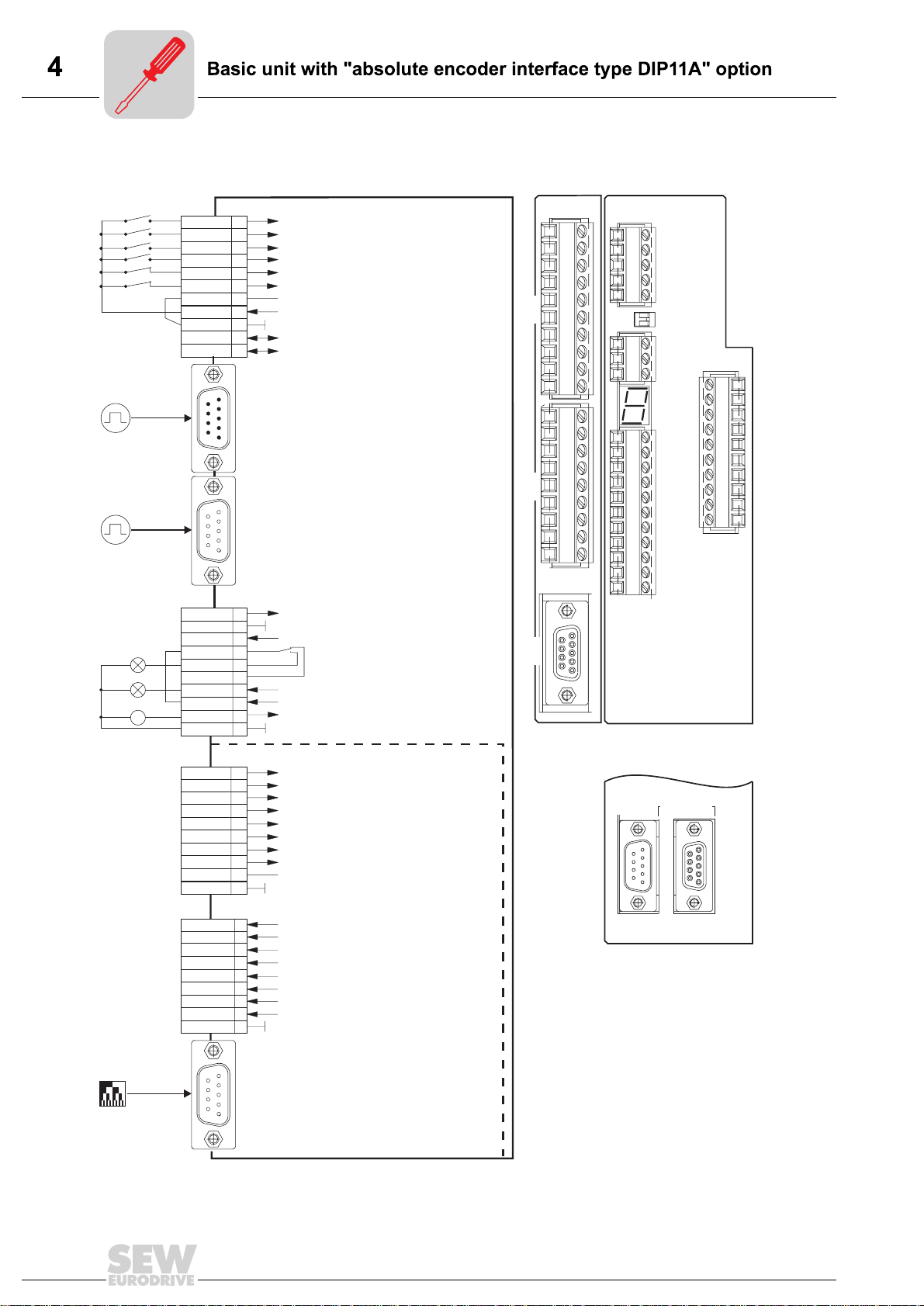
4.2 Basic unit with "absolute encoder interface type DIP11A" option
24 V
-
DIØØ
DIØ1
DIØ2
DIØ3
DIØ4
DIØ5
DCOM
VO24
DGND
ST11
ST12
6
9
9
6
X13:
1
/Controller inhibit
2
Enable/rapid stop
3
Reset
4
No function
5
/Limit switch CW
6
/Limit switch CCW
7
Reference X13:DIØØ...DIØ5
8
+24V output
9
10
11
1
5
Reference potential binary signals
RS-485+
RS-485-
X14: (MDV/MDS)
Input external encoder,
Incremental encoder 5 V TTL
(Connection MOVIDRIVE
→
MOVIDRIVE
®
operating instructions)
X15: (MDV/MDS)
5
Motor encoder:
Incremental encoder (MDV) or resolver (MDS)
(Connection MOVIDRIVE
1
→
®
operating instructions)
®
DIP
1
2
3
4
5
X
60
6
7
8
9
10
1
2
3
4
X
5
61
6
7
8
9
S11
S12
10
MDF
1
2
X11
3
4
5
mA V↔
R ON OFF↔
1
X12
2
3
1
2
3
1
2
3
4
5
X13
6
7
X10
4
5
6
7
8
9
10
8
9
11
X10:
TF1
DGND
DBØØ
DOØ1-C
DOØ1-NO
DOØ1-NC
DOØ2
VO24
+
=
VI24
DGND
10
X60:
DI1Ø
DI11
DI12
DI13
DI14
DI15
DI16
DI17
DCOM
DGND
10
X61:
DO1Ø
DO11
DO12
DO13
DO14
DO15
DO16
DO17
DGND
TF input
1
Reference potential binary signals
2
/Brake
3
4
5
6
7
8
9
Relay contact/fault
NO relay/fault
NC relay /fault
Referenced
+24V output
+24V input
Reference potential binary signals
1
2
3
No function, since virtual
No function, since virtual
4
terminals are active!
terminals are active!
5
6
7
8
Reference X22:DI1Ø...DI17
9
Reference potential binary signals
1
2
3
No function since virtual
4
terminals are active!
5
6
7
8
Reference potential binary signals
9
DIP11A
62
X
MDV (MDS)
SUPPLYOUT 24V=
X14 X15
ENCODER IN/OUT ENCODER IN
(RESOLVER IN)
SSI
interface
Gray code
X62:
5
9
Absolute encoder
Connection "Positioning with DIP11A Absolute
(
6
Encoder and Absolute Encoder Option"
1
→
Fig. 7: Wiring diagram for basic unit with DIP11A option
14
manual
)
04433AEN
MOVIDRIVE® MD_60A, Absolute Positioning
 Loading...