

Movidrive CS**A,Movidrive CSB31A,Movidrive CSB21A,Movidrive CSS21A,Movidrive CSS31A
Table of contents
 Loading...
SEW Movidrive CS**A,Movidrive CSB31A,Movidrive CSB21A,Movidrive CSS21A,Movidrive CSS31A Series Manual
Drive Technology \ Drive Automation \ System Integration \ Services
Manual
*24842532_0418*
MOVIDRIVE® modular, MOVIDRIVE® system
MOVISAFE®CS..A Safety Card
Edition 04/2018 24842532/EN
SEW-EURODRIVE—Driving the world

Table of contents
Table of contents
1 General information.................................................................................................................. 8
1.1 About this documentation ...............................................................................................8
1.2 Structure of the safety notes ...........................................................................................8
1.2.1 Meaning of signal words ................................................................................ 8
1.2.2 Structure of section-related safety notes........................................................ 8
1.2.3 Structure of embedded safety notes .............................................................. 9
1.3 Rights to claim under limited warranty ............................................................................9
1.4 Content of the documentation.........................................................................................9
1.5 Other applicable documentation ..................................................................................... 9
1.6 Product names and trademarks....................................................................................10
1.7 Copyright notice ............................................................................................................10
2 Safety notes ............................................................................................................................ 11
2.1 Preliminary information ................................................................................................. 11
2.2 User duties....................................................................................................................11
2.3 Target group .................................................................................................................11
2.4 Designated use .............................................................................................................12
2.5 Transport.......................................................................................................................12
2.6 Installation/assembly.....................................................................................................13
2.6.1 Restrictions of use........................................................................................ 13
2.7 Electrical installation .....................................................................................................13
2.8 Definitions ..................................................................................................................... 14
2.9 Startup/operation ..........................................................................................................14
3 Safety concept ........................................................................................................................ 15
3.1 General information ......................................................................................................15
3.2 Notes on stop categories .............................................................................................. 15
3.3 Pluggable safety key.....................................................................................................15
3.4 Identification and authentication ...................................................................................16
3.5 Report and safety check ............................................................................................... 16
3.6 MOVISAFE®CS..A safety concept ............................................................................... 16
3.7 Drive safety functions....................................................................................................17
24842532/EN – 04/2018
3.8 Safety concept of Assist CS..........................................................................................27
3.7.1 STO – Safe Torque Off ................................................................................ 18
3.7.2 SS1(b) – Safe Stop 1 ................................................................................... 19
3.7.3 SS1(c) – Safe Stop 1 ................................................................................... 20
3.7.4 SS2(b) – Safe Stop 2 ................................................................................... 21
3.7.5 SS2(c) – Safe Stop 2 ................................................................................... 22
3.7.6 SOS – Safe Operating Stop ......................................................................... 23
3.7.7 SLA – Safely Limited Acceleration ............................................................... 23
3.7.8 SLS – Safely Limited Speed ........................................................................ 24
3.7.9 SSR – Safe Speed Range ........................................................................... 24
3.7.10 SSM – Safe Speed Monitoring..................................................................... 25
3.7.11 SDI – Safe Direction..................................................................................... 25
3.7.12 SLI – Safely Limited Increment .................................................................... 26
3.7.13 SBC – Safe Brake Control ........................................................................... 26
Manual – MOVISAFE®CS..A Safety Card
3

Table of contents
3.8.1 Safety parameters........................................................................................ 27
3.8.2 Test concept and test procedure.................................................................. 27
4 Safety requirements ............................................................................................................... 28
4.1 Installation requirements...............................................................................................28
4.2 Encoder cable requirements .........................................................................................28
4.2.1 Sine/cosine encoder cable ........................................................................... 28
4.2.2 HTL encoder cable....................................................................................... 29
4.3 Requirements for external sensors and actuators ........................................................ 29
4.4 Startup requirements ....................................................................................................30
4.5 Requirements for stopping in an emergency to EN60204-1 (emergency stop) ...........30
4.6 Encoder requirements...................................................................................................30
4.6.1 Safety encoders at the DR.., DRN.. AC motor. ............................................ 30
4.6.2 Safety encoders on the EDR.., EDRN.. explosion-proof AC motor.............. 31
4.6.3 Safety encoders on the CMP/CMPZ synchronous servomotor.................... 31
4.6.4 Quantization error ........................................................................................ 32
5 Hazard caused by coasting of the drive............................................................................... 33
6 Device structure ..................................................................................................................... 34
6.1 Type designation...........................................................................................................34
6.2 Scope of delivery ..........................................................................................................34
6.3 Compatibility .................................................................................................................35
6.4 MOVISAFE® CSS21A/CSB21A ................................................................................... 36
6.5 MOVISAFE® CSB31A/CSS31A ................................................................................... 37
7 Mechanical installation .......................................................................................................... 38
7.1 Before you start.............................................................................................................38
7.2 Installation of the MOVISAFE®CS..A safety card........................................................38
7.3 Installation of the MOVISAFE®CS..A safety card – MOVIDRIVE® modular................38
7.4 Installation of the MOVISAFE®CS..A safety card – MOVIDRIVE® system .................40
8 Electrical installation.............................................................................................................. 44
8.1 Important note...............................................................................................................44
8.2 Installation instructions..................................................................................................44
8.3 Connection and terminal assignment............................................................................44
8.3.1 Part numbers................................................................................................ 44
8.3.2 Terminal assignment.................................................................................... 45
8.4 Safe disconnection........................................................................................................45
8.5 Safe digital inputs (F-DI.) .............................................................................................. 45
8.5.1 Discrepancy monitoring................................................................................ 47
8.5.2 Interlocking................................................................................................... 47
8.5.3 Signal monitoring ......................................................................................... 48
8.5.4 Pulsed voltage supply and crossfault monitoring ......................................... 48
8.5.5 Sensors with contact (single-channel) ......................................................... 48
8.5.6 Sensors with contact (dual-channel) ............................................................ 50
8.5.7 Active sensors (dual-channel)...................................................................... 51
8.5.8 Sensors with semiconductor outputs (OSSD, dual-channel) ....................... 54
8.6 Safe digital outputs (F-DO.) .......................................................................................... 55
24842532/EN – 04/2018
Manual – MOVISAFE®CS..A Safety Card
4

Table of contents
8.6.1 General information...................................................................................... 55
8.6.2 Capacitive loads........................................................................................... 56
8.6.3 Inductive loads .............................................................................................56
8.6.4 Ohmic loads .................................................................................................57
8.6.5 Information about line diagnostics and test pulses ...................................... 57
8.6.6 Output F_DO-STO .......................................................................................57
8.6.7 Actuator (dual-channel, sourcing / sinking output) ....................................... 58
8.6.8 Actuator (dual-channel, sourcing output) ..................................................... 59
8.6.9 Actuator (single-channel, sourcing output)................................................... 60
8.7 EI7CFS built-in encoder...............................................................................................61
8.7.1 Properties..................................................................................................... 61
8.7.2 Installation .................................................................................................... 61
9 Startup ..................................................................................................................................... 62
9.1 Important note...............................................................................................................62
9.2 General startup instructions ..........................................................................................62
9.3 Startup options 1–2.....................................................................................................62
9.3.1 Option 1: Independent operation (no connection to PROFIsafe) ................. 62
9.3.2 Option 2: With PROFIsafe connection ......................................................... 63
9.4 Adjusting the maximum test duration for load with unknown capacitance....................63
9.5 Parameterization of the drive safety functions ..............................................................64
9.5.1 Prerequisites ................................................................................................64
9.5.2 Parameterization procedure......................................................................... 64
9.5.3 Encoder error muting ................................................................................... 65
9.5.4 Test mode ....................................................................................................66
9.6 Startup of the fieldbus and the higher-level F-PLC .......................................................66
9.6.1 Prerequisites ................................................................................................66
9.6.2 Setting the PROFIsafe address ................................................................... 66
9.7 Operating states............................................................................................................67
9.7.1 Operating state “Operation” ......................................................................... 67
9.7.2 Operating state “Parameterization” .............................................................. 67
9.7.3 Operating state “Safe state” after critical fault.............................................. 67
9.8 Safety-relevant acceptance ..........................................................................................67
9.8.1 Sequence ..................................................................................................... 68
9.8.2 Creating an acceptance report..................................................................... 68
9.8.3 Structure of the acceptance report............................................................... 68
9.8.4 Confirming acceptance ................................................................................ 69
9.9 Restoring the delivery state ..........................................................................................69
9.9.1 Prerequisites ................................................................................................69
9.9.2 Procedure..................................................................................................... 69
10 Data exchange with higher-level controller ......................................................................... 70
10.1 Introduction ................................................................................................................... 70
10.2 F-periphery access of the safety card in the TIA portal ................................................70
24842532/EN – 04/2018
10.3 F process output data ................................................................................................... 73
10.1.1 Number of safety cards on the MOVI-C® CONTROLLER............................ 70
10.2.1 F-periphery-data component of the safety card ........................................... 71
Manual – MOVISAFE®CS..A Safety Card
5

Table of contents
10.3.1 CSB21A profile variant “Technology Bus STO” ........................................... 73
10.3.2 CSB31A profile variant “Technology Bus F-DO”.......................................... 74
10.3.3 CSS21A/CSS31A profile variant “Technology Standard” ............................ 76
10.3.4 Substitute values.......................................................................................... 78
10.4 F process input data .....................................................................................................78
10.4.1 CSB21A profile variant “Technology Bus STO” ........................................... 78
10.4.2 CSB31A profile design "Technology Bus F-DO".......................................... 80
10.4.3 CSS21A/CSS31A profile variant “Technology Standard” ............................ 82
10.4.4 Substitute values.......................................................................................... 85
10.5 Acknowledgment of safety card ....................................................................................85
10.5.1 Acknowledgment of PROFIsafe data exchange .......................................... 85
10.5.2 Acknowledgment of safety card ................................................................... 85
11 Response times ...................................................................................................................... 86
11.1 Calculation of response times.......................................................................................86
11.1.1 Encoder........................................................................................................ 87
11.1.2 Safe digital input F-DI................................................................................... 87
11.1.3 Safe communication..................................................................................... 88
11.1.4 Selection of a drive safety function via a safe digital input in independent
operation ......................................................................................................88
11.1.5 Selection of a drive safety function via safe communication........................ 88
11.1.6 Response time in case of limit value violation in independent operation ..... 91
11.1.7 Response time in case of limit value violation with safe communication ..... 92
11.1.8 Deselection of a drive safety function via a safe digital input....................... 93
11.1.9 Deselection of a drive safety function via safe communication.................... 93
12 Service..................................................................................................................................... 94
12.1 Modification/changes to the device...............................................................................94
12.2 Waste disposal..............................................................................................................94
12.3 Status LEDs ..................................................................................................................94
12.3.1 "F-RUN” LED................................................................................................ 95
12.3.2 "F-ERR" LED................................................................................................ 95
12.4 Error states of the MOVISAFE®CS..A safety card ...................................................... 96
12.4.1 Error classes ................................................................................................96
12.5 Error diagnostics ...........................................................................................................98
12.5.1 Error messages............................................................................................ 99
12.5.2 Diagnostics with MOVISUITE®Assist CS.. ................................................ 100
12.5.3 Diagnostics with PROFIsafe connection .................................................... 100
12.5.4 Fault memory .............................................................................................101
12.6 Device replacement .................................................................................................... 101
12.6.1 Device replacement with MOVI-C®CONTROLLER................................... 102
12.6.2 Device replacement with MOVISUITE®...................................................... 102
13 Technical data....................................................................................................................... 103
13.1 General technical data ................................................................................................103
13.2 General electrical data ................................................................................................103
13.2.1 Power consumption of the option cards ..................................................... 103
13.3 Safe digital inputs........................................................................................................104
24842532/EN – 04/2018
Manual – MOVISAFE®CS..A Safety Card
6

Table of contents
13.4 Sensor supply ............................................................................................................. 105
13.5 Safe digital outputs .....................................................................................................105
13.6 Characteristic safety values ........................................................................................106
13.6.1 Drive safety functions without encoder evaluation ..................................... 106
13.6.2 Drive safety functions with encoder evaluation .......................................... 106
Index ...................................................................................................................................... 107
24842532/EN – 04/2018
Manual – MOVISAFE®CS..A Safety Card
7
General information
About this documentation
1
1 General information
1.1 About this documentation
The current version of the documentation is the original.
This documentation is an integral part of the product. The documentation is written for
all employees who assemble, install, start up, and service this product.
Make sure this documentation is accessible and legible. Ensure that persons responsible for the machinery and its operation as well as persons who work on the product
independently have read through the documentation carefully and understood it. If you
are unclear about any of the information in this documentation or require further information, contact SEW‑EURODRIVE.
1.2 Structure of the safety notes
1.2.1 Meaning of signal words
The following table shows the grading and meaning of the signal words for safety
notes.
Signal word Meaning Consequences if disregarded
DANGER Imminent hazard Severe or fatal injuries
WARNING Possible dangerous situation Severe or fatal injuries
CAUTION Possible dangerous situation Minor injuries
NOTICE Possible damage to property Damage to the product or its envir-
onment
INFORMATION Useful information or tip: Simplifies
handling of the product.
1.2.2 Structure of section-related safety notes
Section-related safety notes do not apply to a specific action but to several actions
pertaining to one subject. The hazard symbols used either indicate a general hazard
or a specific hazard.
This is the formal structure of a safety note for a specific section:
SIGNAL WORD
Type and source of hazard.
Possible consequence(s) if disregarded.
• Measure(s) to prevent the hazard.
Meaning of the hazard symbols
The hazard symbols in the safety notes have the following meaning:
Hazard symbol Meaning
Manual – MOVISAFE®CS..A Safety Card
8
General hazard
24842532/EN – 04/2018
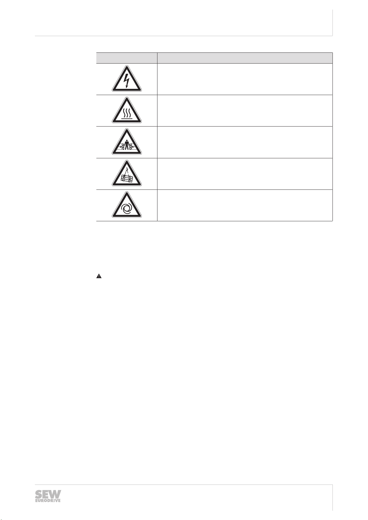
Hazard symbol Meaning
Warning of dangerous electrical voltage
Warning of hot surfaces
Warning of risk of crushing
Warning of suspended load
Warning of automatic restart
General information
Rights to claim under limited warranty
1
1.2.3 Structure of embedded safety notes
Embedded safety notes are directly integrated into the instructions just before the description of the dangerous action.
This is the formal structure of an embedded safety note:
SIGNAL WORD Type and source of hazard. Possible consequence(s) if disreg-
arded. Measure(s) to prevent the hazard.
1.3 Rights to claim under limited warranty
Read the information in this documentation. This is essential for fault-free operation
and fulfillment of any rights to claim under limited warranty. Read the documentation
before you start working with the product.
1.4 Content of the documentation
This documentation contains additional safety-related information and conditions for
operation in safety-related applications.
1.5 Other applicable documentation
This document supplements the operating instructions and limits the application notes
according to the following information. Use this document only in connection with the
operating instructions.
• "MOVIDRIVE® modular" and "MOVIDRIVE® system" operating instructions
24842532/EN – 04/2018
• "MOVIDRIVE® modular, MOVIDRIVE® system – Multi-Encoder Card CES11A"
manual
Manual – MOVISAFE®CS..A Safety Card
9

General information
Product names and trademarks
1
• Addendum to the operating instructions "Safety Encoders and Safety Brakes, AC
Motors DR.., DRN.., EDR.., EDRN"
• Addendum "Safety-Rated Encoders – Functional Safety for Synchronous Motors"
1.6 Product names and trademarks
The brands and product names in this documentation are trademarks or registered
trademarks of their respective titleholders.
1.7 Copyright notice
©2018SEW‑EURODRIVE. All rights reserved. Unauthorized reproduction, modification, distribution or any other use of the whole or any part of this documentation is
strictly prohibited.
10
24842532/EN – 04/2018
Manual – MOVISAFE®CS..A Safety Card

2 Safety notes
2.1 Preliminary information
The following general safety notes have the purpose to avoid injury and damage to
property. They primarily apply to the use of products described in this documentation.
If you use additional components also observe the relevant warning and safety notes.
2.2 User duties
As the user, you must ensure that the basic safety notes are observed and complied
with. Make sure that persons responsible for the machinery and its operation as well
as persons who work on the device independently have read through the documentation carefully and understood it.
As the user, you must ensure that all of the work listed in the following is carried out
only by qualified specialists:
• Setup and installation
• Installation and connection
• Startup
• Maintenance and repairs
• Shutdown
• Disassembly
Ensure that the persons who work on the product pay attention to the following regulations, conditions, documentation, and information:
• National and regional safety and accident prevention regulations
• Warning and safety signs on the product
• All other relevant project planning documents, installation and startup instructions,
and wiring diagrams
• Do not assemble, install or operate damaged products
• All system-specific specifications and conditions
Ensure that systems in which the product is installed are equipped with additional
monitoring and protection devices. Observe the applicable safety regulations and legislation governing technical work equipment and accident prevention regulations.
Safety notes
Preliminary information
2
2.3 Target group
Specialist for
mechanical work
24842532/EN – 04/2018
Any mechanical work may only be performed by adequately qualified specialists. Specialists in the context of this documentation are persons familiar with the design,
mechanical installation, troubleshooting, and maintenance of the product who possess
the following qualifications:
• Qualification in the mechanical area in accordance with the national regulations
• Familiarity with this documentation
Manual – MOVISAFE®CS..A Safety Card
11

Safety notes
Designated use
2
Specialist for electrotechnical work
Additional qualification
Instructed persons All work in the areas of transportation, storage, operation and waste disposal must be
Any electrotechnical work may only be performed by electrically skilled persons with a
suitable education. Electrically skilled persons in the context of this documentation are
persons familiar with electrical installation, startup, troubleshooting, and maintenance
of the product who possess the following qualifications:
• Qualification in the electrotechnical area in accordance with the national regulations
• Familiarity with this documentation
In addition to that, these persons must be familiar with the valid safety regulations and
laws, as well as with the requirements of the standards, directives, and laws specified
in this documentation. The persons must have the express authorization of the company to operate, program, parameterize, label, and ground units, systems, and circuits
in accordance with the standards of safety technology.
carried out by persons who are trained appropriately. The purpose of the instruction is
that the persons are capable of performing the required tasks and work steps in a safe
and correct manner.
2.4 Designated use
The product is intended for installation in inverters.
The product is a programmable safety control for manufacturing safety cutoffs and
functions. The product is intended for use:
• In emergency off devices
• As a safety-related component pursuant to Machinery Directive 2006/42/EC
• As a PES for risk reduction pursuant to EN61508
• In safety circuits according to EN60204-1
• As a PES for functional safety pursuant to EN62061
• As a SRP/CS pursuant to ENISO13849
• As a device for implementing the safety functions pursuant to EN61800-5-2
In the case of installation in electrical systems or machines, it is prohibited to start the
proper operation of the product until it is determined that the machine meets the requirements stipulated in the local laws and directives.
The standards given in the declaration of conformity apply to the product.
Unintended or improper use of the product may result in severe injury to persons and
damage to property.
Technical data and information on the connection conditions are provided on the
nameplate and in chapter "Technical data" in the documentation. Always comply with
the data and conditions.
2.5 Transport
12
Manual – MOVISAFE®CS..A Safety Card
Inspect the shipment for damage as soon as you receive the delivery. Inform the shipping company immediately about any damage. If the product is damaged, it must not
be assembled, installed or started up.
Observe the following notes when transporting the device:
• Ensure that the product is not subject to mechanical impact during transportation.
24842532/EN – 04/2018

If necessary, use suitable, sufficiently dimensioned handling equipment.
Observe the information on climatic conditions in chapter "Technical data" of the documentation.
2.6 Installation/assembly
Ensure that the product is installed and cooled according to the regulations in the documentation.
Protect the product from strong mechanical strain. The product and its mounting parts
must never protrude into the path of persons or vehicles. Ensure that components are
not deformed and insulation spaces are not changed, particularly during transportation
and handling. Electric components must not be mechanically damaged or destroyed.
Observe the notes in chapter "Mechanical installation" (→ 2 38) in the documentation.
2.6.1 Restrictions of use
Safety notes
Installation/assembly
2
The following applications are prohibited unless the device is explicitly designed for
such use:
• Use in potentially explosive atmospheres
• Use in areas exposed to harmful oils, acids, gases, vapors, dust, and radiation
• Operation in applications with impermissibly high mechanical vibration and shock
loads in excess of the regulations stipulated in EN61800-5-1
• Use at an elevation of more than 4000m above sea level
2.7 Electrical installation
Ensure that all of the required covers are correctly attached after carrying out the electrical installation.
Make sure that preventive measures and protection devices comply with the applicable regulations (e.g. EN60204-1 or EN61800-5-1).
24842532/EN – 04/2018
Manual – MOVISAFE®CS..A Safety Card
13

Safety notes
Definitions
2
2.8 Definitions
2.9 Startup/operation
• The designation "F-DI." stands for a safe input.
• The designation "F-DO." stands for a safe output.
• The designation "CS..A" is used as a generic term for all derivatives of the
MOVISAFE®CS product series. If a particular derivative is referred to in the
manual, then the complete designation is used.
• The term "safe" used in this manual refers to the classification as a safe function
according to ENISO13849-1.
• PROFIsafe is a technology standard for a safe fieldbus system.
• The "Assist CS.." parameter tool is the parameterization interface in MOVISUITE
for the MOVISAFE® CS..A safety card.
Observe the safety notes in the chapters "Startup" (→ 2 62) and Operation in the
documentation.
Depending on the degree of protection, products may have live, uninsulated, and
sometimes moving or rotating parts, as well as hot surfaces during operation.
Mechanical blocking or internal drive safety functions of the product can cause a motor standstill. Eliminating the cause of the problem or performing a reset may result in
the drive restarting automatically. If, for safety reasons, this is not permitted for the
drive-controlled machine, first disconnect the product from the supply system and then
start troubleshooting.
The fact that the operation LED and other display elements are no longer illuminated
does not indicate that the product has been disconnected from the supply system and
no longer carries any voltage.
In the event of deviations from normal operation, switch the product off. Possible deviations are increased temperatures, noise, or vibration, for example. Determine the
cause. Contact SEW‑EURODRIVE if necessary.
Do not deactivate monitoring and protection devices of the machine or system even
for a test run.
Additional preventive measures may be required for applications with increased hazard potential. Be sure to check the effectiveness of the protection devices after every
modification.
®
14
24842532/EN – 04/2018
Manual – MOVISAFE®CS..A Safety Card

3 Safety concept
3.1 General information
The MOVISAFE® CS..A safety card is a safe assembly with safe digital inputs and outputs and, depending on the parameterization, safe communication.
MOVISAFE® CS..A is fully integrated in the MOVIDRIVE® modular inverter or the
MOVIDRIVE® system inverter. This means that MOVISAFE®CS..A internally activates
the STO drive safety function of the inverter. The output stage of the inverter is safely
switched off by the STO function.
The safety concept is based on a safe state existing for all safe process values. A safe
state of the MOVISAFE®CS..A safety card is defined as follows:
• The internal output F-DO_STO is activated as N.C. As a result, the drive safety
function STO is switched and the output stage of the inverter is switched off.
• All other existing safe digital outputs are activated as N.C.
• With parameterized safe communication, either substitute values are sent for the
data (i.e. all data is "0"), or the communication is interrupted.
Safety concept
General information
3
3.2 Notes on stop categories
• With stop category 0, the output stage of the inverter is switched off, irrespective of
the setpoints set.
• With stop category 1, the MOVISAFE®CS..A safety card monitors the stopping of
the drive and subsequently interrupts the supply of power to the motor:
– With SS1(c), the output stage of the inverter is switched off after the parameter-
ized delay time.
– With SS1(b), the stopping of the drive is monitored. At a standstill, the output
stage of the inverter is switched off.
• With stop category 2, the MOVISAFE®CS..A safety card monitors the stopping of
the drive and subsequently monitors the safe operating stop:
– With SS2(c), the safe operating stop is monitored after the parameterized delay
time.
– With SS2(b), the stopping of the drive and the subsequent safe operating stop
are monitored.
3.3 Pluggable safety key
The safety key must be inserted upon activation of the MOVISAFE®CS..A safety card
and may not be removed when the safety card is activated.
The parameterization data of the MOVISAFE®CS..A safety card is divided into application-related data and a key data set. The key data set ensures the data integrity.
The application-related data is stored in the device. The application-related data is released with the aid of the key data set on the pluggable safety key. The safety card
becomes operational only if the key data set on the pluggable safety key matches the
parameterization.
24842532/EN – 04/2018
Manual – MOVISAFE®CS..A Safety Card
15

Safety concept
Identification and authentication
3
The pluggable safety key is also used to establish a location reference in the system.
Since the application-related data set is released only with the matching key data set
on the pluggable safety key, the location reference can be established in this way. It is
the user’s responsibility to secure the location reference of the safety key in the system. The data for safe communication is also stored on the pluggable safety key, because this data has the same location reference. This ensures that, in the event of a
device replacement, the application-related data and the communication data are
available again immediately.
3.4 Identification and authentication
The unique identification of the device and an authentication of the user are necessary
for the steps "Parameterize", "Create report" and "Confirm validation". To identify the
device, the ID of the pluggable safety key is entered in the login dialog of the device.
The ID is printed on the pluggable safety key. This mechanism ensures that the parameterization tool Assist CS.. is connected to the correct device. The user is authenticated via the entry of a password.
3.5 Report and safety check
The acceptance report can be created once the parameters are downloaded. The acceptance of the safety card within the system can be carried out (see chapter "Requirements for commissioning") with this acceptance report. Following acceptance,
this must be confirmed in the safety card. The confirmation is not a replacement for
the test that must be carried out. The "Checksum of the report" of the safety card is
announced as confirmation of the acceptance.
3.6 MOVISAFE®CS..A safety concept
• The MOVISAFE® CS..A safety card is an integrated, safe assembly that can be
operated with or without PROFIsafe connection. MOVISAFE® CS..A is equipped
with safe inputs and outputs (F-DI, F-DO) and is available in the following designs.
MOVISAFE® CSB21A safety card:
– 4 safe inputs
MOVISAFE® CSS21A safety card:
– 4 safe inputs
– 2 safe dual-channel outputs
MOVISAFE® CSB31A safety card:
– 4 safe inputs
MOVISAFE
®CS..A
safety
concept
16
– 2 safe dual-channel outputs
– 2nd encoder slot (not used for functional safety)
MOVISAFE® CSS31A safety card:
– 4 safe inputs
– 2 safe dual-channel outputs
– 2nd encoder slot (not used for functional safety)
Manual – MOVISAFE®CS..A Safety Card
24842532/EN – 04/2018
Safety concept
Drive safety functions
• The MOVISAFE® CS..A safety card can release or safely deactivate the output
stage of the inverter. The switching state of the internal output F-DO_STO, and
thus the STO drive safety function, must be stable once within 60 seconds for at
least 2seconds (2.5seconds with extended diagnostics).
• The safety concept of the MOVISAFE®CS..A safety card is based on a safe state
existing for all safe process values. For the MOVISAFE®CS..A, this value is "0" for
all F-DI inputs and F-DO outputs.
• The system was designed pursuant to IEC61508 for SIL3 and ENISO13849-1 for
Performance Level e.
• The MOVISAFE® CSS21A and CSS31A safety cards can reliably monitor motion
functions in conjunction with the following safety encoders:
– ES7S/EG7S
– AS7W/AG7W
– AK0H/AK1H
– EI7C FS
The MOVISAFE® CS..A safety card switches off the output stage of the inverter
when a limit value of an active drive safety function is exceeded.
3
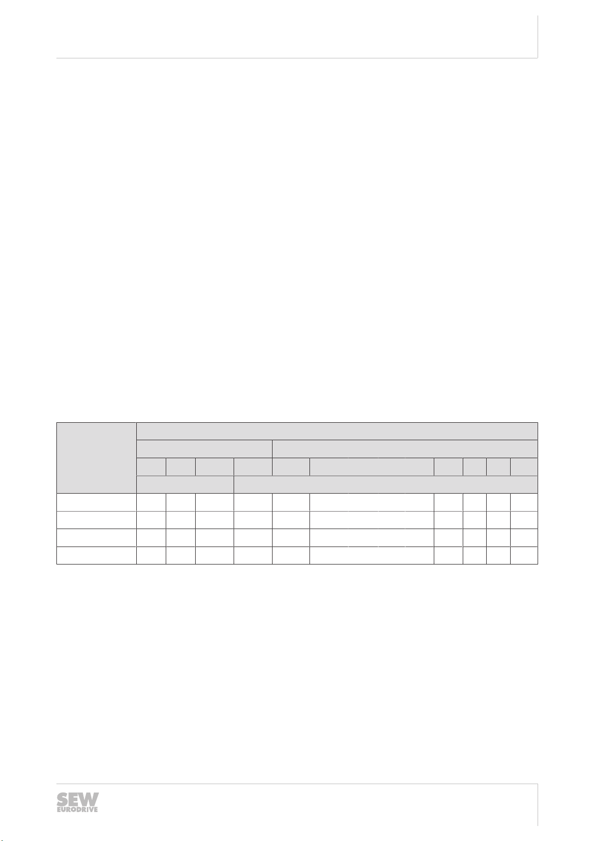
3.7 Drive safety functions
This chapter describes the drive safety functions pursuant to EN61800-5-2. The following table shows the availability of the drive safety functions described below, depending on the respective MOVISAFE®CS..A safety card used.
MOVISAFE
safety card
CSB21A x x
CSS21A x x x x x x x x x x x x x
CSB31A
CSS31A
1) has a second encoder connection (not used for functional safety)
®
Idle state Motion
STO SBC SS1(c) SS1(b) SS2(c) SS2(b) SOS SLS SSM SSR SDI SLI SLA
1)
1)
x x x
x x x x x x x x x x x x x
Drive safety functions
Only with FS encoder
24842532/EN – 04/2018
Manual – MOVISAFE®CS..A Safety Card
17
Safety concept
t
V
t
1
Drive safety functions
3
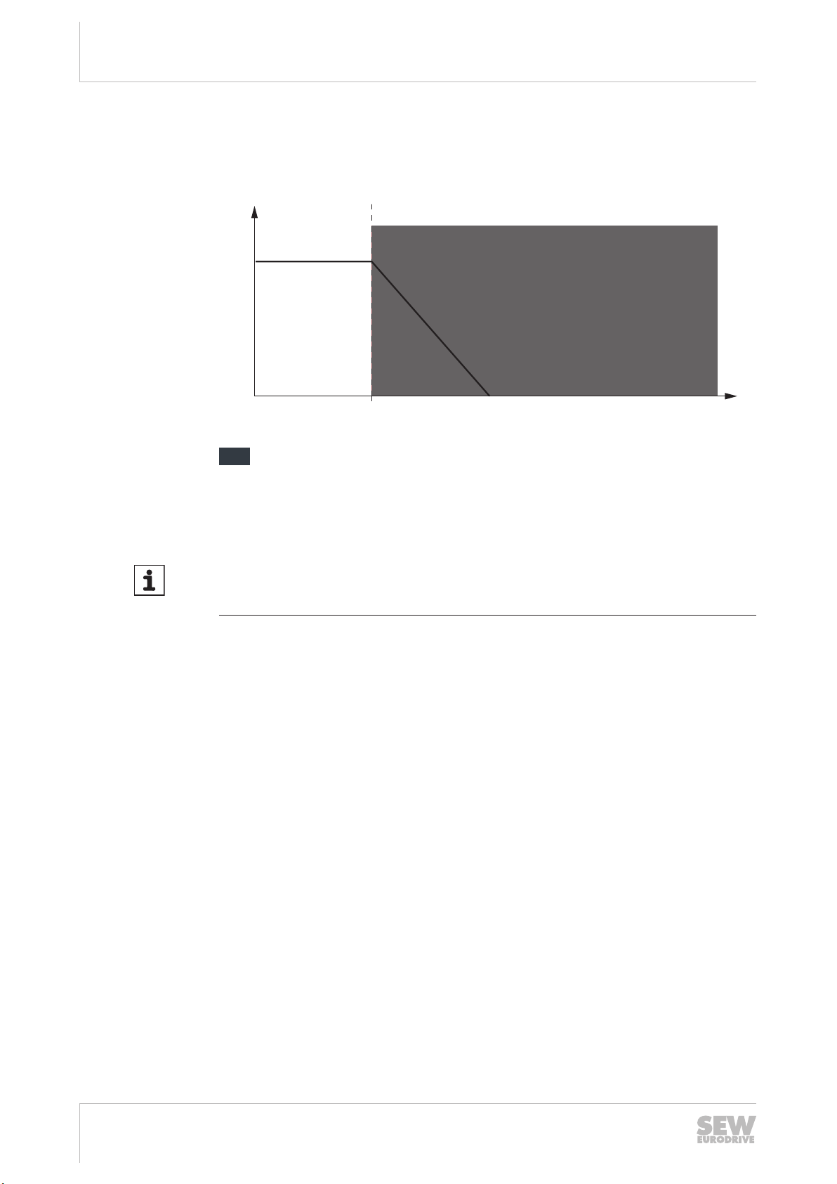
3.7.1 STO – Safe Torque Off
If the STO function is activated, the drive inverter no longer supplies power to the motor. As a result, the drive cannot generate torque. This drive safety function corresponds to a non-controlled stop according to EN60204-1, stop category 0.
9007201225613323
Drive safety function trips
=
v =
t =
t1=
Speed
Time
Point of time when STO is triggered.
INFORMATION
The motor coasts to a halt or is stopped mechanically.
Controlled standstill is preferred, if possible.
24842532/EN – 04/2018
18
Manual – MOVISAFE®CS..A Safety Card

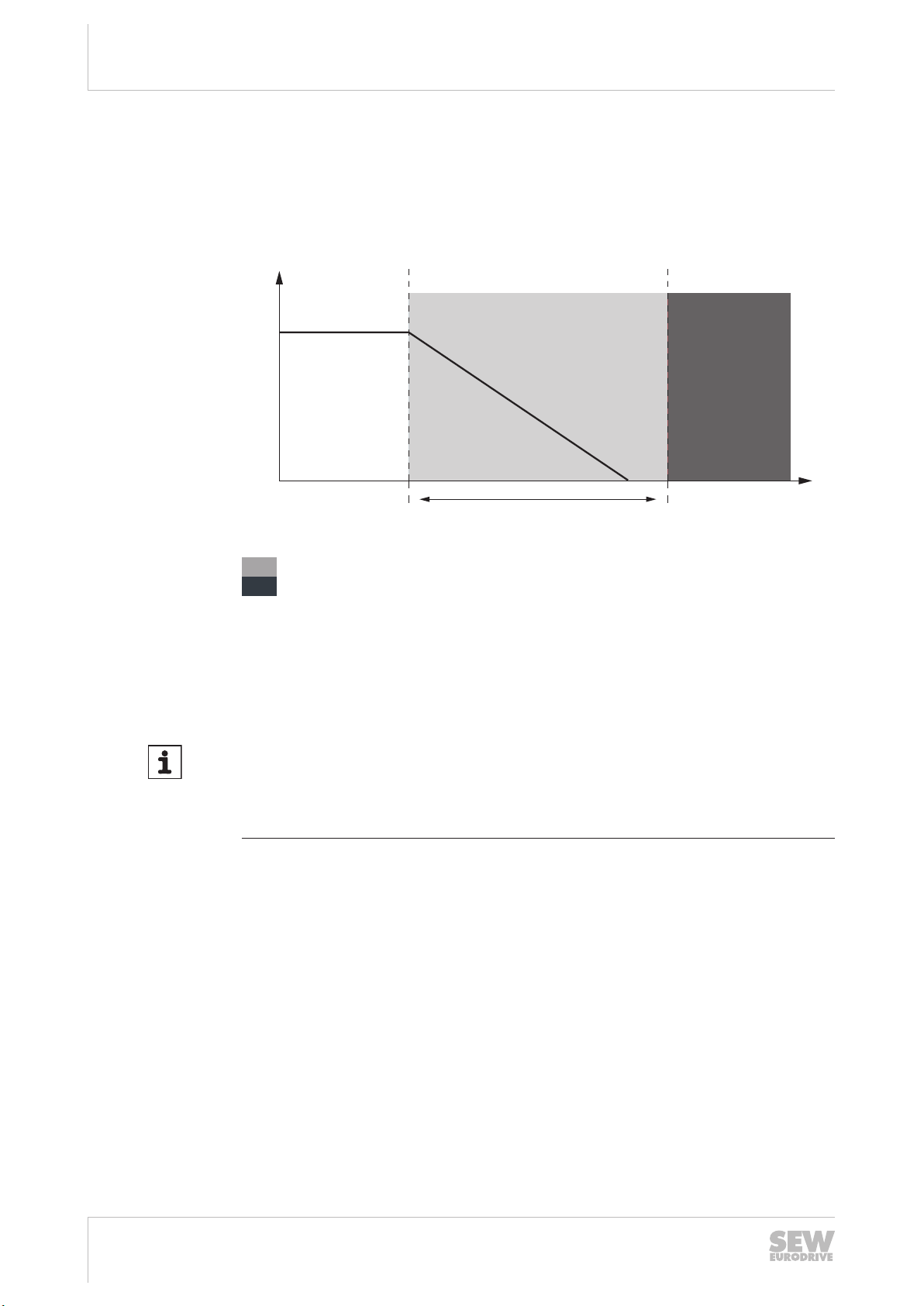
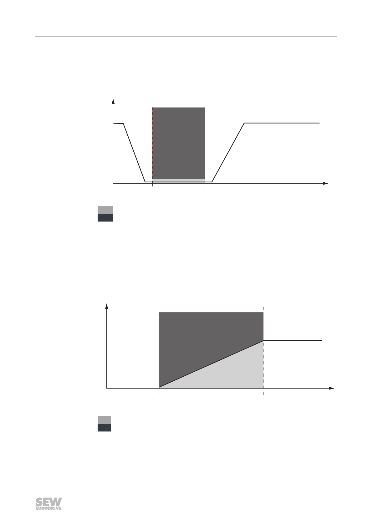
3.7.2 SS1(b) – Safe Stop 1
t
V
t
1
t
2
When the SS1(b) function is active, the drive inverter brings the motor to a standstill
electrically. The deceleration is monitored. The STO drive safety function is triggered
when the monitored deceleration is exceeded or when standstill is reached.
This drive safety function corresponds to a controlled stop of the drive according to
EN60204-1, stop category 1.
Safety concept
Drive safety functions
3
Drive safety function monitored
=
Drive safety function trips
=
Speed
v =
Time
t =
Point in time when SS1(b) is activated and motor deceleration is triggered.
t1=
Point of time when STO is triggered.
t2=
9007201225616011
24842532/EN – 04/2018
Manual – MOVISAFE®CS..A Safety Card
19
Safety concept
t
2
t
1
t
V
∆t
Drive safety functions
3
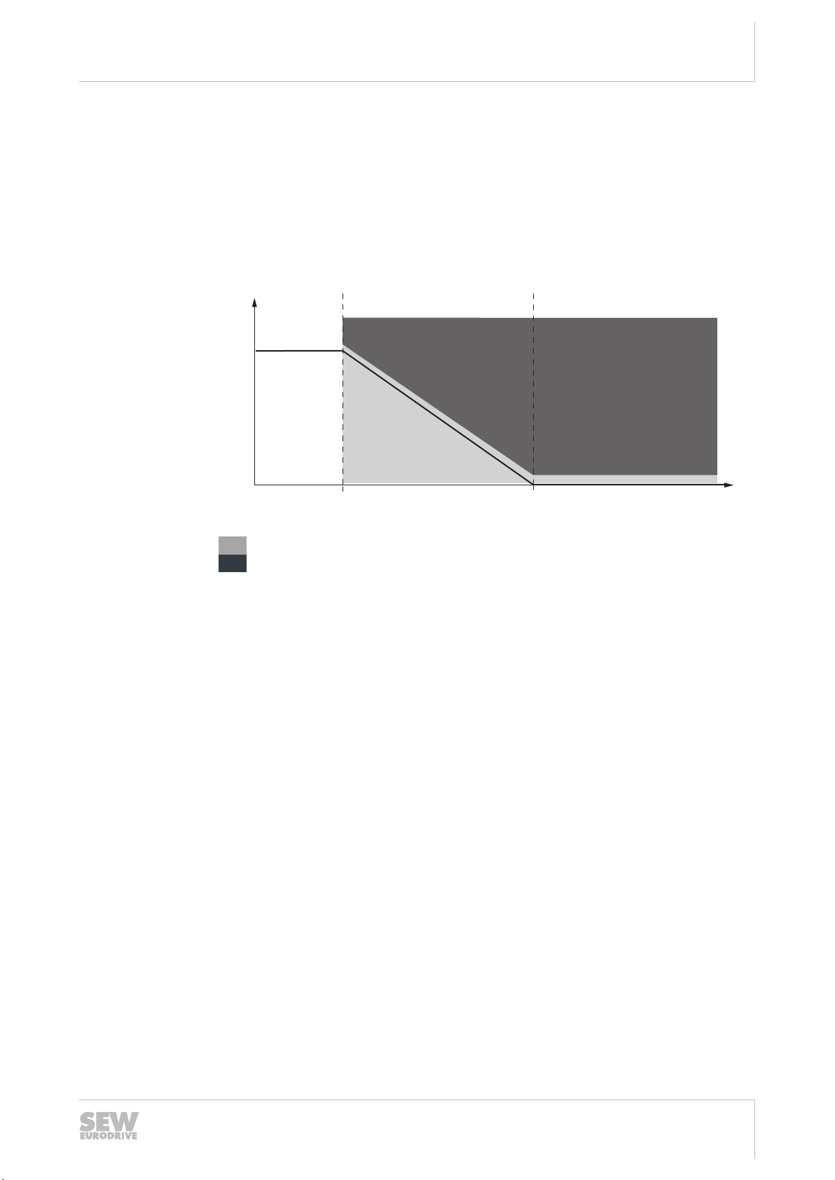
3.7.3 SS1(c) – Safe Stop 1
When the SS1(c) function is active, the drive inverter brings the motor to a standstill
electrically. The drive safety function STO is triggered after a specified, safety-related
time.
This drive safety function corresponds to a controlled stop of the drive according to
EN60204-1, stop category 1.
9007201225618443
Drive safety function monitored
=
Drive safety function trips
=
Speed
v =
Time
t =
Point of time when SS1(c) is activated and motor deceleration is triggered.
t1=
Point of time when STO is triggered.
t2=
Δt =
Safety-relevant period of time
INFORMATION
• The SS1(c) function does not monitor the stopping of the drive.
• The safety-relevant period of time Δt allows the drive to come to a stop. In the
event of a fault, the drive does not come to a stop and becomes de-energized at
the time t2 (STO).
24842532/EN – 04/2018
20
Manual – MOVISAFE®CS..A Safety Card
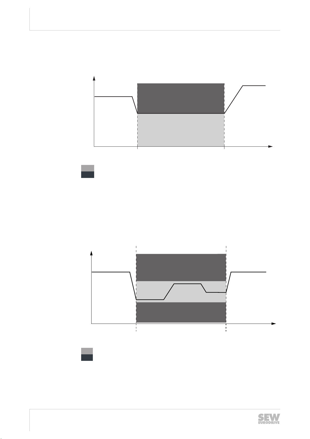
3.7.4 SS2(b) – Safe Stop 2
t
V
t
1
t
2
When the SS2(b) function is active, the drive inverter brings the motor to a standstill
electrically. The deceleration is monitored. The position must be safely monitored after
standstill (SOS function according to EN 61800-5-2). The STO drive safety function
will be triggered if the deceleration value is exceeded while stopping or if movement
occurs during standstill. STO means that standstill has to be ensured by a mechanical
brake.
This drive safety function corresponds to a controlled stop of the drive according to
EN60204-1, stop category 2.
Safety concept
Drive safety functions
3
v =
t =
t1=
t2=
9007201225698059
Drive safety function monitored
=
Drive safety function trips
=
Speed
Time
Point in time when SS2(b) is activated and motor deceleration is triggered.
Point in time when SOS is triggered.
24842532/EN – 04/2018
Manual – MOVISAFE®CS..A Safety Card
21

Safety concept
t
1
t
2
t
∆t
V
Drive safety functions
3
3.7.5 SS2(c) – Safe Stop 2
When the SS2(c) function is active, the drive inverter brings the motor to a standstill
electrically. At standstill, the drive inverter delivers the power to keep the motor in position. The position must be safely monitored after a specified, safety-relevant time has
elapsed (SOS function according to EN 61800-5-2). Any movement at standstill triggers the STO drive safety function. STO means that standstill has to be ensured by a
mechanical brake.
This drive safety function corresponds to a controlled stop of the drive according to
EN60204-1, stop category 2.
9007201429937291
Drive safety function monitored
=
Drive safety function trips
=
Speed
v =
Time
t =
Point of time when SS2(c) is activated and motor deceleration is triggered.
t1=
Point in time when SOS is triggered.
t2=
Δt =
Safety-relevant period of time
INFORMATION
• The SS2(c) function does not monitor the stopping of the drive.
• The safety-relevant period of time Δt allows the drive to come to a stop. In the
event of a fault, the drive does not come to a stop. It will not be de-energized until
the time t2 (STO).
24842532/EN – 04/2018
22
Manual – MOVISAFE®CS..A Safety Card
3.7.6 SOS – Safe Operating Stop
t
1
t
2
t
V
t
1
t
2
t
V
The SOS function prevents the motor from deviating from the stop position by more
than a specified value. The drive inverter delivers the power to keep the motor in position. If the specified value is exceeded, the drive safety function will be triggered and
an error response will be initiated at the same time.
Drive safety function monitoring
=
Drive safety function trips
=
v =
t =
t1=
t2=
Speed
Time
Point in time when SOS is triggered.
Point in time when SOS is deactivated.
Safety concept
Drive safety functions
9007201225700491
3
3.7.7 SLA – Safely Limited Acceleration
The SLA function prevents a movement from exceeding a specified acceleration
value. If the permitted acceleration limit is exceeded, the drive safety function will be
triggered and an error response will be initiated at the same time.
9007201225705355
Drive safety function monitoring
=
Drive safety function trips
24842532/EN – 04/2018
v =
t =
t1=
t2=
=
Speed
Time
Point in time when SLA is activated.
Point in time when SLA is deactivated.
Manual – MOVISAFE®CS..A Safety Card
23
Safety concept
t
V
t
1
t
2
t
1
t
2
t
V
Drive safety functions
3
3.7.8 SLS – Safely Limited Speed
The SLS function prevents the drive from exceeding a specified speed. If the permitted speed is exceeded, the safety function will be triggered and an error response will
be initiated at the same time.
v =
t =
t1=
t2=
Drive safety function monitoring
=
Drive safety function trips
=
Speed
Time
Time when SLS is activated.
Time when SLS is deactivated.
9007201225702923
3.7.9 SSR – Safe Speed Range
The SSR function prevents the speed of the drive from exceeding a specified range. If
the permitted speed range is exceeded or not achieved, the safety function will be
triggered and an error response will be initiated at the same time.
9007201659986827
Drive safety function monitoring
v =
t =
t1=
t2=
=
Drive safety function trips
=
Speed
Time
Point in time when SSR is activated.
Point in time when SSR is deactivated.
24842532/EN – 04/2018
24
Manual – MOVISAFE®CS..A Safety Card
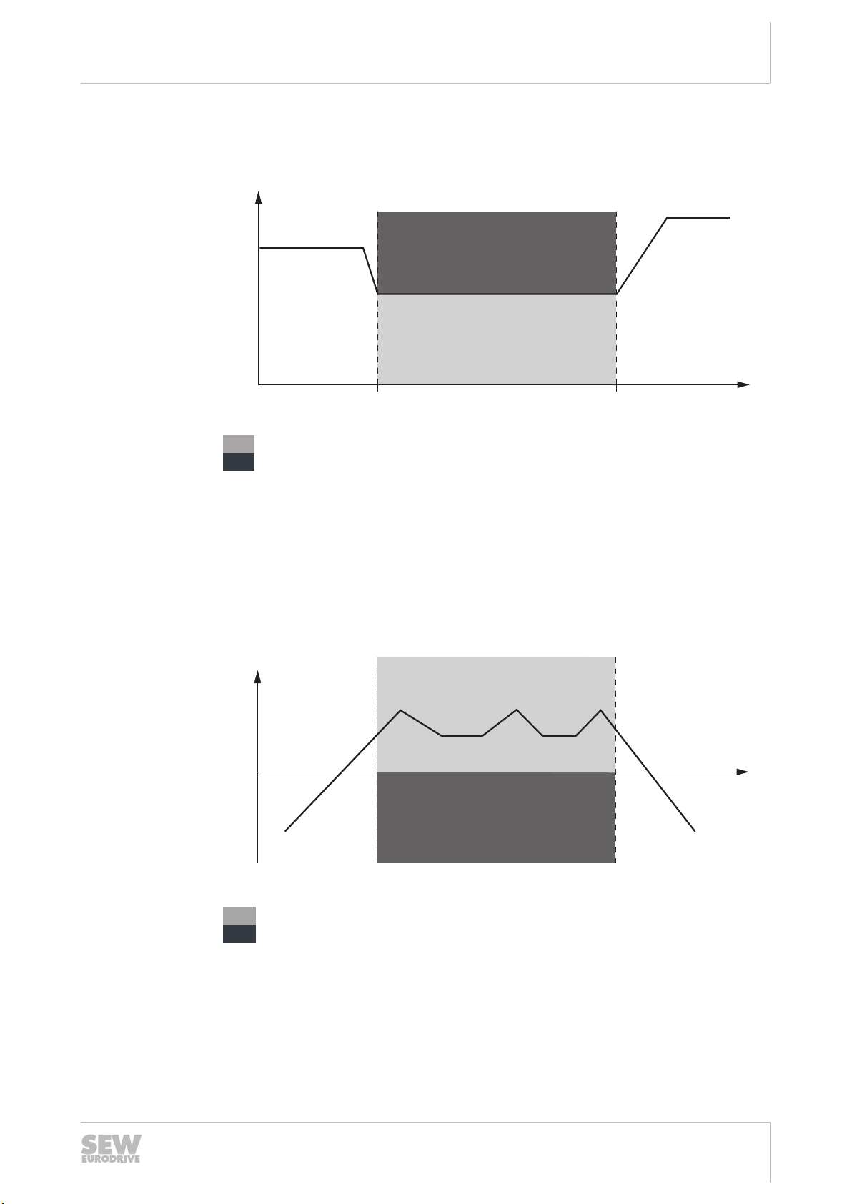
3.7.10 SSM – Safe Speed Monitoring
t
V
t
1
t
2
t
V
t
1
t
2
The SSM function monitors whether the drive exceeds a specified speed. An exceeding of the allowed speed is signaled.
Drive safety function monitoring
=
Drive safety function trips
=
v =
t =
t1=
t2=
Speed
Time
Point in time at which SSM is activated.
Point in time at which SSM is deactivated.
Safety concept
Drive safety functions
9007201225702923
3
3.7.11 SDI – Safe Direction
The SDI function prevents movement in an unintended direction. If this condition is violated, the drive safety function will be triggered and an error response will be initiated
at the same time (usually STO or SS1).
9007201225717643
Drive safety function monitored
=
Drive safety function trips
=
v =
t =
t1=
t2=
Speed
Time
Point in time when SDI is activated.
Point in time when SDI is deactivated.
24842532/EN – 04/2018
Manual – MOVISAFE®CS..A Safety Card
25
Safety concept
S
V
∆S ∆S
S
1
S
2
S
3
t
1
t
V
Drive safety functions
3
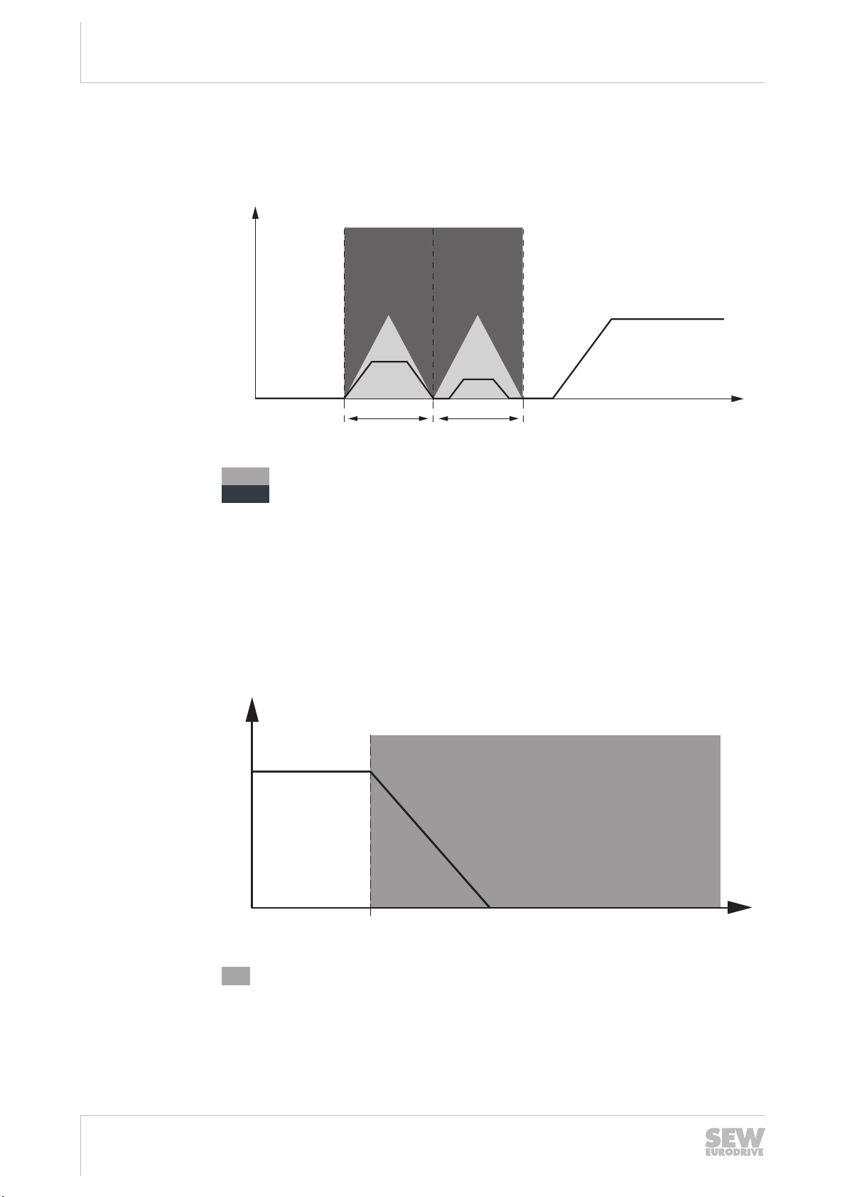
3.7.12 SLI – Safely Limited Increment
The SLI function prevents a movement from exceeding a specified increment. If the
limit value of the increment is not respected, the drive safety function will be triggered
and an error response will be initiated at the same time.
v =
s =
s1, s2=
s2, s3=
Δs =
Drive safety function monitoring
=
Drive safety function trips
=
Speed
Distance
Point in time when SLI is activated.
Point in time when SLI is deactivated.
Safe increment
9007201225720459
3.7.13 SBC – Safe Brake Control
The SBC function provides a safe output signal for controlling an external brake. This
means no power is supplied to release the brake electrically.
18014400788450571
Drive safety function interrupts the power supply to the brake.
=
Speed
v =
Time
t =
Point in time when the drive is stopped.
t1=
26
Manual – MOVISAFE®CS..A Safety Card
24842532/EN – 04/2018

3.8 Safety concept of Assist CS..
3.8.1 Safety parameters
For all drive safety functions, MOVISAFE® CS.. A is equipped with setting options
through safety parameters.
The safety parameters determine the behavior of the corresponding drive safety functions and are therefore safety-relevant. All safety parameters are combined in the
parameter set.
3.8.2 Test concept and test procedure
The parameters of the MOVISAFE® CS..A safety card are set using an engineering
PC with the "Assist CS.." parameterization tool. As the PC and the "Assist CS.." parameterization tool are not safety-related and therefore possibly not error-free, the safety
concept prescribes the following measures:
• Identification of the MOVISAFE®CS..A.
• The ID of the safety key must be entered via a dialog when establishing a connection with the MOVISAFE® CS..A safety card.
• Guided parameter setting procedure with the parameterization tool "Assist CS.."
with integrated safety features such as plausibility check of entries. The user must
compare the entered parameters with the device parameters and confirm (verify)
them.
• Completion of the parameterization by verification of parameters, assisted by the
parameterization tool "Assist CS.." with subsequent creation of an acceptance protocol for validation of the safety functions.
Safety concept
Safety concept of Assist CS..
3
24842532/EN – 04/2018
Manual – MOVISAFE®CS..A Safety Card
27

Safety requirements
Installation requirements
4
4 Safety requirements
4.1 Installation requirements
• Power cables and the safe control cables must be routed separately.
• The wiring technology used must comply with EN 60204-1.
• The safe control cables of the MOVISAFE® CS..A safety card must be installed
pursuant to EMC requirements. Observe the following information:
– Observe the regulations applicable to the application and the information in the
– If the safe outputs and/or inputs are wired in a dual-channel configuration, the
• Make sure that no parasitic voltages can be generated in safe control cables.
• Outside of a closed installation room, safety-related control cables must be protected against external damage.
• Only voltage sources with protective separation (SELV/PELV) pursuant to
EN60204-1 and EN61131-2 are permitted for any DC24V supply voltages to the
MOVIDRIVE® modular/system. In case of a single fault, the voltage between the
outputs or between any output and grounded parts may not exceed 60V DC. This
also applies to sensors that are supplied by a separate voltage supply and connected to the MOVISAFE® CS..A safety card.
• The encoder cable must not carry a TF signal when connecting an EI7CFS built-in
encoder to the MOVIDRIVE® modular/system.
• The safety card must be protected against conductive dirt, e.g. by installing it in a
control cabinet with degree of protection IP54 pursuant to IEC60529.
Assuming that the presence of conductive dirt can be excluded at the installation
site, a control cabinet with a correspondingly lower degree of protection is also
permitted if in accordance with the applicable standards (e.g. EN 60204‑1). The
same applies to temporary condensation, e.g. due to rapid changes in ambient
temperature.
operating instructions for the inverter.
corresponding cables must be routed closely together. The cables must be of
the same length; a length difference between the cables of ≤3% is permissible.
4.2 Encoder cable requirements
4.2.1 Sine/cosine encoder cable
• Use a shielded encoder cable. Connect the shield at both ends.
• Max. length of the encoder cable: 100m
• Use the prefabricated encoder cables from SEW-EURODRIVE. Observe the following requirements if you use other encoder cables:
– Encoder cable length ≤50m
The cross section of each core of the encoder cable must be ≥0.25mm2. The
resistance load per unit length of the cores must not exceed 78 Ω/km (at
20°C).
– Encoder cable length >50m:
The cross section of the cores for the encoder voltage supply and GND must
be ≥0.5mm2. The resistance load per unit length of these cores must not exceed 39Ω/km. The resistance load per unit length of the signal cores must not
exceed 78Ω/km (at 20°C).
28
Manual – MOVISAFE®CS..A Safety Card
24842532/EN – 04/2018

– Differential signal pairs (e.g. the track signals A and A, B and B, C and C, Data
– The encoder cable may exhibit the following maximum capacitances per unit
– In the signal path from the encoder to the inverter, the encoder signals must not
4.2.2 HTL encoder cable
• Use a shielded encoder cable. Connect the shield at both ends.
• Max. length of the encoder cable: 100m
• Use the prefabricated encoder cables from SEW-EURODRIVE. Observe the following requirements if you use other encoder cables:
– The cross section of each core of the encoder cable must be ≥0.25mm2. The
Safety requirements
Requirements for external sensors and actuators
+ and Data-) must be routed via twisted cores.
length:
Capacitance per unit length core / core: CA’=70pF/m
Capacitance per unit length core / shield: CS’=120pF/m
branch off to other devices.
resistance load per unit length of the cores must not exceed 78 Ω/km (at
20°C).
4
– The encoder cable may not conduct any signals other than the encoder signals,
i.e., the encoder signals must not be conducted with other signals in the same
cable. The encoder signals must be conducted in twisted pairs as follows:
UB and GND
A+ and A-
B+ and B-
– The encoder cable may exhibit the following maximum capacitances per unit
length:
Capacitance per unit length core / core: CA’=70pF/m
Capacitance per unit length core / shield: CS’=120pF/m
– In the signal path from the encoder to the inverter, the encoder signals must not
branch off to other devices.
4.3 Requirements for external sensors and actuators
• The project planner and the user of the system or machine are responsible for the
number and utilization of external sensors and actuators for connection with the
safe inputs and outputs of the MOVISAFE®CS..A safety card.
Note that, as a rule, the greater part of the maximum permissible probability of
hazardous errors for the respectively preferred safety classes originates with the
sensors and actuators.
• Use the calculation tool "SISTEMA" from the "BGIA" (Institute for Occupational
Health and Safety of the German Employer’s Liability Insurance Associations) for
selecting suitable sensor technology and actuators.
• To meet the required performance level (PL/SIL), you must use suitable and correspondingly qualified sensors and actuators, and observe the relevant wiring diagrams and information in the chapters "Safe inputs" and "Safe outputs". The per-
24842532/EN – 04/2018
missible encoders are described in the chapter "Encoder requirements".
Manual – MOVISAFE®CS..A Safety Card
29
Safety requirements
Startup requirements
4
4.4 Startup requirements
Following parameterization and startup, the system startup engineer must check and
document whether all of the drive safety functions are being executed correctly.
For MOVIDRIVE® applications with safe disconnection of the drive
• as per stop category 1 or 2 in accordance with EN60204-1,
• with restart inhibit in accordance with EN1037,
you must, as a general rule, carry out and document startup checks of the disconnecting device and the correct wiring.
This is supported by the "Assist CS.." parameterization tool with an acceptance protocol.
INFORMATION
• In order to avoid a hazard in the intended application when a fault occurs, the user
• The user must ensure implementation of the requirements of the
must check whether the fault response time of each drive safety function is then
shorter than the maximum permitted fault response time of the application. The
maximum permitted fault response time may not be exceeded!
required performance level pursuant to ENISO13849-1.
4.5 Requirements for stopping in an emergency to EN60204-1 (emergency
stop)
The MOVISAFE® CS..A safety cards, in combination with an emergency stop command device and the external control, are suitable for implementing an emergency
stop in accordance with EN 60204-1. In order to ensure protection against unanticipated restarting of the drive pursuant to EN1037, the start command must be canceled
via the external controller.
WARNING
In the case of a pending travel command, the drive restarts after acknowledging the
safety card.
Severe or fatal injuries.
• Cancel the travel command before acknowledging the safety card.
4.6 Encoder requirements
4.6.1 Safety encoders at the DR.., DRN.. AC motor.
The safety encoders described below are designated for use with DR.., DRN.. motors.
It is not permitted to mount them to other motors.
30
Motor sizes Encoders Part number
DR..71 – DR..132
DRN80–DRN132S
Manual – MOVISAFE®CS..A Safety Card
with without
Connection cover
ES7S 13642898 13642715
AS7W 13643916 13643878
24842532/EN – 04/2018
Loading...