

SEW MDR60A, MDR61B Operating Instructions Manual
Drive Technology \ Drive Automation \ System Integration \ Services
Operating Instructions
MOVIDRIVE
Edition 06/2011 19300816 / EN
®
MDR60A/61B Regenerative Power Supply Unit
SEW-EURODRIVE—Driving the world

Contents
Contents
1 General Information ............................................................................................ 6
1.1 Use of this documentation ......................................................................... 6
1.2 Structure of the safety notes ....................................................................... 6
1.3 Rights to claim under limited warranty ........................................................ 7
1.4 Exclusion of liability..................................................................................... 7
1.5 Copyright notice .......................................................................................... 7
1.6 Product names and trademarks.................................................................. 7
2 Safety Notes ........................................................................................................ 8
2.1 General ....................................................................................................... 8
2.2 Target group ............................................................................................... 8
2.3 Designated use ........................................................................................... 9
2.4 Transportation and storage......................................................................... 9
2.5 Installation................................................................................................. 10
2.6 Electrical connection ................................................................................. 10
2.7 Safe disconnection.................................................................................... 10
2.8 Operation .................................................................................................. 10
3 Unit Structure .................................................................................................... 12
3.1 Type designation, nameplates and scope of delivery ............................... 12
3.2 Scope of delivery ...................................................................................... 14
3.3 Size 2 ........................................................................................................ 15
3.4 Size 3 ........................................................................................................ 16
3.5 Size 4 ........................................................................................................ 17
3.6 Size 6 ........................................................................................................ 18
3.7 Size 7 ........................................................................................................ 19
4 Installation (MDR60A0150/0370/0750 and MDR61B1600/2500) ..................... 21
4.1 Installation notes ....................................................................................... 21
4.2 Information regarding UL .......................................................................... 29
4.3 Strain relief................................................................................................ 31
4.4 Wiring diagrams ........................................................................................ 32
4.5 Conversion into an IT network unit ........................................................... 39
4.6 Touch guard for power terminals .............................................................. 41
4.7 Optional scope of delivery for size 7 ........................................................ 44
5 Startup (MDR60A0150/0370/0750 and MDR61B1600/2500) ........................... 56
5.1 Evaluation of the ready signal................................................................... 56
5.2 Parameter setting P52_ "Power off control".............................................. 59
5.3 Startup with DBG60B keypad ................................................................... 60
5.4 Operation of MOVITOOLS
5.5 MOVIDRIVE
5.6 Setting for CFC/servo mode ..................................................................... 65
6 MDR61B1600/2500 – Parameters..................................................................... 66
6.1 Overview of parameters............................................................................ 66
6.2 Explanation of the parameters .................................................................. 68
®
MDR61B DC link upload process ...................................... 63
®
MotionStudio................................................ 60
Operating Instructions – MOVIDRIVE® MDR60A/61B
3

Contents
7 Operation (MDR60A0150/0370/0750 and MDR61B1600/2500)....................... 78
7.1 Operating characteristics .......................................................................... 78
7.2 Operating displays .................................................................................... 79
7.3 Key assignment for DBG60B .................................................................... 81
7.4 Memory card ............................................................................................. 82
8 Service (MDR60A0150/0370/0750 and MDR61B1600/2500) ........................... 83
8.1 Fault information ....................................................................................... 83
8.2 Error messages and list of errors.............................................................. 85
8.3 SEW Electronics Service .......................................................................... 91
9 Introduction (MDR60A1320-503-00)................................................................. 92
9.1 About these operating instructions............................................................ 92
9.2 Terminology .............................................................................................. 92
9.3 Legal provisions ........................................................................................ 93
10 Safety Notes (MDR60A1320-503-00)................................................................ 95
10.1 General information .................................................................................. 95
11 Technical Data (MDR60A1320-503-00) .......................................................... 101
11.1 Characteristics ........................................................................................ 101
11.2 General technical data ............................................................................ 101
11.3 Rated data .............................................................................................. 102
11.4 Current carrying capacity ........................................................................ 102
11.5 Fuses and cable cross sections.............................................................. 103
12 Installation (MDR60A1320-503-00)................................................................. 104
12.1 Mechanical installation............................................................................ 104
12.2 Notes on electrical installation ................................................................ 105
12.3 Electrical connection ............................................................................... 107
12.4 Installation in a CE typical drive system.................................................. 112
13 Startup (MDR60A1320-503-00) ....................................................................... 115
13.1 Initial operation........................................................................................ 115
13.2 Ready signal ........................................................................................... 116
14 Configuration (MDR60A1320-503-00) ............................................................ 117
14.1 Important notes on configuration ............................................................ 117
15 Operation and Service (MDR60A1320-503-00) ............................................. 121
15.1 Reset....................................................................................................... 121
15.2 Operating displays .................................................................................. 122
15.3 Maintenance ........................................................................................... 124
16 Technical Data – Basic Unit .......................................................................... 125
16.1 CE marking, UL approval and C-Tick ..................................................... 125
16.2 General technical data ............................................................................ 126
16.3 MOVIDRIVE
®
MDR60A/61B unit series, sizes 2 to 7 ............................. 128
16.4 Smallest wire bending space (EN 61800-5-1) ........................................ 129
16.5 MOVIDRIVE
16.6 MOVIDRIVE
16.7 MOVIDRIVE
®
MDR60A0150/0370 size 2 and size 3 ............................. 130
®
MDR60A0750/1320 size 4 and size 6 ............................ 131
®
MDR61B1600/2500 size 7............................................... 133
16.8 Dimension drawings................................................................................ 134
4
Operating Instructions – MOVIDRIVE® MDR60A/61B

Contents
17 Declarations of Conformity ............................................................................ 139
17.1 MOVIDRIVE
Index................................................................................................................. 140
®
MDR60A/61B................................................................... 139
Operating Instructions – MOVIDRIVE® MDR60A/61B
5
1
General Information
Use of this documentation
1 General Information
1.1 Use of this documentation
The documentation is an integral part of the product and contains important information
on operation and service. The documentation is written for all employees who assemble,
install, startup, and service this product.
The documentation must be accessible and legible. Make sure that persons responsible
for the system and its operation, as well as persons who work independently on the unit,
have read through the documentation carefully and understood it. If you are unclear
about any of the information in this documentation, or if you require further information,
contact SEW-EURODRIVE.
1.2 Structure of the safety notes
1.2.1 Meaning of the signal words
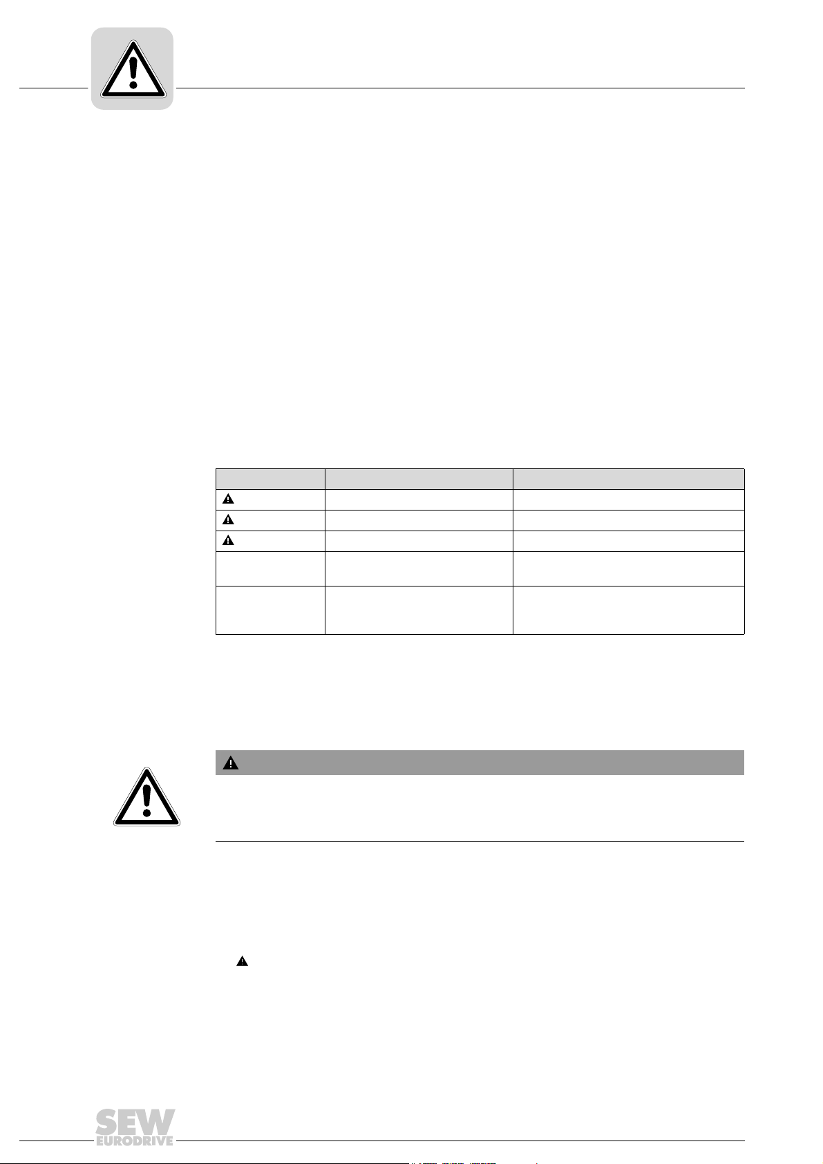
The following table shows the grading and meaning of the signal words for safety notes,
notes on potential risks of damage to property, and other notes.
Signal word Meaning Consequences if disregarded
DANGER Imminent danger Severe or fatal injuries
WARNIN G Possible dangerous situation Severe or fatal injuries
CAUTION Possible dangerous situation Minor injuries
NOTICE Possible damage to property Damage to the drive system or its envi-
INFORMATION Useful information or tip: Simpli-
fies the handling of the drive
system.
1.2.2 Structure of the section-related safety notes
Section safety notes do not apply to a specific action, but to several actions pertaining
to one subject. The used symbols indicate either a general or a specific hazard.
This is the formal structure of a section safety note:
SIGNAL WORD
Type and source of danger.
Possible consequence(s) if disregarded.
• Measure(s) to prevent the danger.
1.2.3 Structure of the embedded safety notes
Embedded safety notes are directly integrated in the instructions just before the description of the dangerous action.
ronment
This is the formal structure of an embedded safety note:
• SIGNAL WORD Nature and source of hazard.
Possible consequence(s) if disregarded.
– Measure(s) to prevent the danger.
6
Operating Instructions – MOVIDRIVE® MDR60A/61B

Rights to claim under limited warranty
1.3 Rights to claim under limited warranty
A requirement of fault-free operation and fulfillment of any rights to claim under limited
warranty is that you adhere to the information in the documentation. Read the documentation before you start working with the unit!
1.4 Exclusion of liability
General Information
1
You must comply with the information contained in this documentation to ensure safe
operation of the MOVIDRIVE
achieve the specified product characteristics and performance requirements. SEW-EURODRIVE assumes no liability for injury to persons or damage to equipment or property
resulting from non-observance of the documentation. In such cases, any liability for defects is excluded.
1.5 Copyright notice
© 2010 – SEW-EURODRIVE. All rights reserved.
Unauthorized duplication, modification, distribution or any other use of the whole or any
part of this documentation is strictly prohibited.
1.6 Product names and trademarks
All brands and product names in this documentation are trademarks or registered trademarks of their respective titleholders.
®
MDX60B/61B regenerative power supply unit and to
Operating Instructions – MOVIDRIVE® MDR60A/61B
7

2
2 Safety Notes
2.1 General
Safety Notes
General
The following basic safety notes must be read carefully to prevent injury to persons and
damage to property. The operator must ensure that the basic safety notes are read and
adhered to. Make sure that persons responsible for the system and its operation, as well
as persons who work independently on the unit, have read through the operating instructions carefully and understood them. If you are unclear about any of the information in
this documentation or if you require further information, please contact SEW-EURODRIVE.
Never install or start up damaged products. Submit a complaint to the shipping company
immediately in the event of damage.
During operation, regenerative power supply units can have live, bare and movable or
rotating parts as well as hot surfaces, depending on their degree of protection.
Removing covers without authorization, improper use as well as incorrect installation or
operation may result in severe injuries to persons or damage to property.
Refer to the documentation for additional information.
2.2 Target group
Only qualified electricians are authorized to install, startup or service the units or correct unit faults (observing IEC 60364 or CENELEC HD 384 or DIN VDE 0100 and
IEC 60664 or DIN VDE 0110 as well as national accident prevention guidelines).
Qualified personnel in the context of these basic safety notes are: All persons familiar
with installation, assembly, startup and operation of the product who possess the necessary qualifications.
Any activities regarding transportation, storage, operation, and disposal must be carried
out by persons who have been instructed appropriately.
8
Operating Instructions – MOVIDRIVE® MDR60A/61B

2.3 Designated use
Regenerative power supply units are components intended for installation in electrical
systems or machines.
In case of installation in machines, startup of the regenerative power supply unit (meaning the start of designated use) is prohibited until it is determined that the machine meets
the requirements stipulated in the Machinery Directive 2006/42/EC; EN 60204 must be
observed.
Startup (i.e. the start of designated use) is only permitted under observance of the EMC
(2004/108/EC) directive.
Regenerative power supply units meet the requirements stipulated in the low voltage directive 2006/95/EC. The harmonized standards of the EN 61800-5-1/DIN VDE T105 series in connection with EN 60439-1/VDE 0660 part 500 and EN 60146/VDE 0558 are
applied to these drive inverters.
You must observe the technical data and information on the connection requirements
as provided on the nameplate and in the documentation.
Safety Notes
Designated use
2
2.4 Transportation and storage
You must observe the notes on transportation, storage and proper handling. Observe
the climatic conditions as stated in the section "General technical data".
Operating Instructions – MOVIDRIVE® MDR60A/61B
9

2
2.5 Installation
Safety Notes
Installation
The units must be installed and cooled according to the regulations and specifications
in the corresponding documentation.
Protect the regenerative power supply units from improper strain. Ensure that components are not deformed and/or insulation spaces are maintained, particularly during
transportation. Avoid contact with electronic components and contacts.
Drive inverters contain components that can be damaged by electrostatic energy and
improper handling. Prevent mechanical damage or destruction of electric components
(may pose health risk)
The following applications are prohibited unless the unit is explicitly designed for such
use:
• Use in potentially explosive atmospheres.
• Use in areas exposed to harmful oils, acids, gases, vapors, dust, radiation, etc.
• Use in non-stationary applications which are subject to mechanical vibration and impact loads in excess of the requirements in EN 61800-5-1.
2.6 Electrical connection
Observe the applicable national accident prevention guidelines when working on live
drive inverters (for example, BGV A3).
Electrical installation is to be carried out in compliance with pertinent regulations (e.g.
cable cross sections, fusing, protective conductor connection). For any additional information, refer to the applicable documentation.
You will find notes on EMC compliant installation, such as shielding, grounding, arrangement of filters and routing of lines, in the documentation of the drive inverters. Always
observe these notes even with drive inverters bearing the CE marking. The manufacturer of the system or machine is responsible for maintaining the limits established by
EMC legislation.
Protective measures and protection devices must comply with the regulations in force
(e.g. EN 60204 or EN 61800-5-1).
Required preventive measure: Grounding the unit.
MOVIDRIVE
lit display LED indicates a DC link voltage. Do not touch power connections. Check that
there is no voltage present before touching power connections even if the LED display
indicates that there is no voltage.
2.7 Safe disconnection
®
B, size 7 has an additional display LED under the lower front cover. The
2.8 Operation
10
The unit meets all requirements for safe disconnection of power and electronic connections in accordance with EN 61800-5-1. All connected circuits must also satisfy the requirements for safe disconnection.
Systems with integrated regenerative power supply units must be equipped with additional monitoring and protection devices according to the applicable safety guidelines,
Operating Instructions – MOVIDRIVE® MDR60A/61B

Safety Notes
Operation
such as the law governing technical equipment, accident prevention regulations, etc.
The operating software may be used to make changes to the drive inverter.
Do not touch live components or power connections immediately after disconnecting the
drive inverters from the supply voltage because there may still be some charged capacitors. Note the respective reference plates on the drive inverter.
Keep all covers and doors closed during operation.
The fact that the status LED and other display elements (such as the display LED on
size 7 units) are no longer illuminated does not indicate that the unit has been disconnected from the power supply and no longer carries any voltage.
Check that there is no voltage present before touching power connections even if the
LED display indicates that there is no voltage.
Mechanical blocking or internal safety functions of the unit can cause a motor standstill.
Eliminating the cause of the problem or performing a reset may result in the drive restarting automatically. If, for safety reasons, this is not permitted for the driven machine,
disconnect the unit from the supply system before correcting the error.
2
Operating Instructions – MOVIDRIVE® MDR60A/61B
11
3
Unit Structure
Type designation, nameplates and scope of delivery
3 Unit Structure
3.1 Type designation, nameplates and scope of delivery
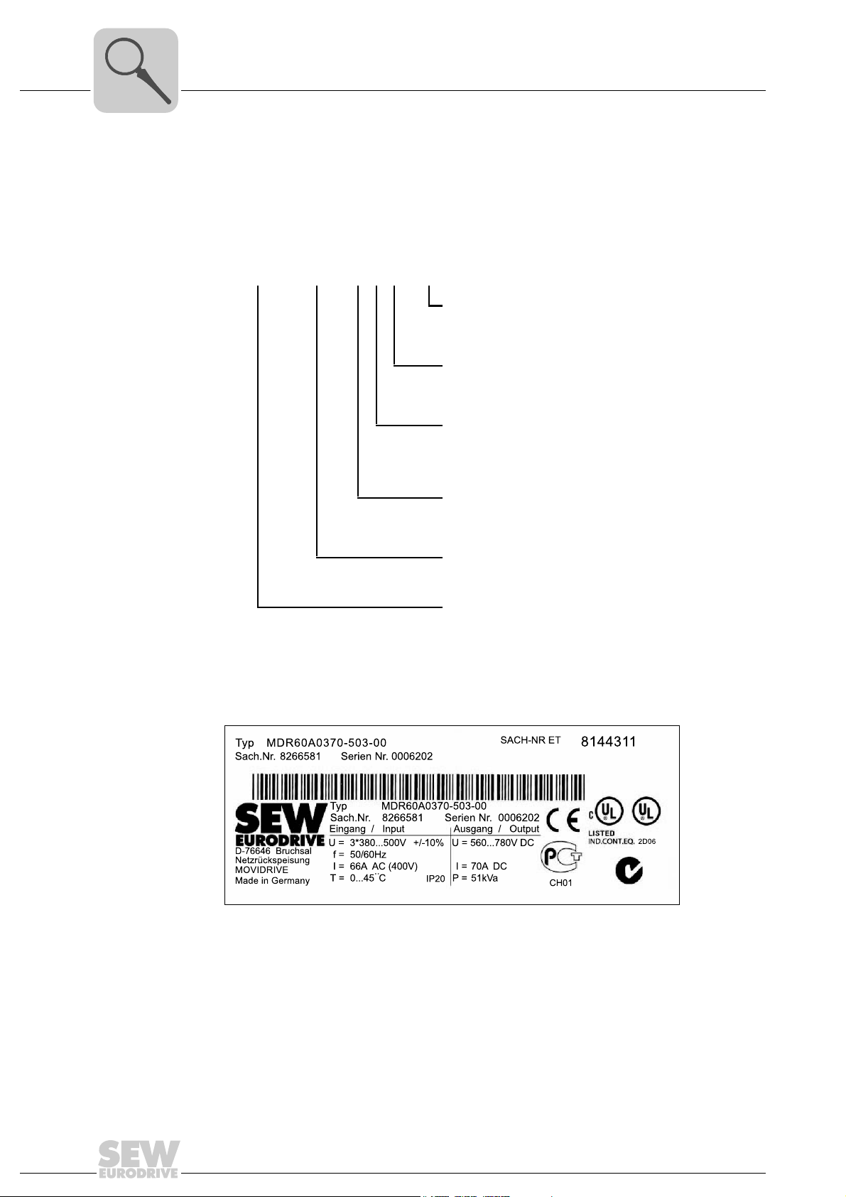
3.1.1 Type designation
The following diagram shows the type designation of the MOVIDRIVE
generative power supply unit:
MDR60A 0370 - 5 0 3 - 00
Design
Connection type 3 = 3-phase
®
MDX60/61B re-
00 = Standard
00/L = Coated pcbs
3.1.2 Example: Nameplate sizes 2 - 4
With MDR60A size 2 – 4, the nameplate is locate on the front of the device.
Supply system end:
Radio interference
suppression
Supply voltage 5 = AC 380 – 500 V
Recommended
inverter connected
load
Series and generation
0 = No radio interference suppression
0370 = 37 kW
MDR60A/61B = Regenerative
power supply
12
1877000715
Operating Instructions – MOVIDRIVE® MDR60A/61B

Type designation, nameplates and scope of delivery
Typ MDR60A1320-503-00
Sach.Nr 08279527 Serien Nr. DCV200 0111
Eingang / Input Ausgang / Output
D-76646 Bruchsal U= 3*380V...500V +/-10% U= 560...780VDC
Netzrückspeisung F= 50/60Hz
MOVIDRIVE I= 289A AC (400V) I= 350A DC
Made in Germany T= 0…40°C P= 200kW
ͺͿ͵ʹͿ΅Ͷ
Sachnr . 18244491 Sernr . 0123456
MDR61B1600-503-00 / L
EINGANG / INPUT AUSGANG / OUTPUT
U= 3*380 . . 500V + / -10%
F= 50 . . . 60Hz + / - 5%
I = 250 A AC ( 400V )
T = 0 . . . 40 C IP 00
U= 620 . . . 780 V DC
F= 0. . . 180Hz
I = 255 A DC
P = 173 k VA Lastart M
3.1.3 Example: Nameplate size 6
With MDR60A size 6, the nameplate is locate on the front of the device.
3.1.4 Example: System nameplate size 7
With MDR61B size 7, the system nameplate is located on the top front cover.
Type: MDR61B2500-503-4-00 / L
S0# : 01.0123456789.0001.11
Unit Structure
4013223819
3
Type: MDR61B2500-503-4-00 / L
P / N: 18250963 S0# : 01.0123456789.0001.11
Steuerkopf / Control Unit
D-76646 Bruchsal
MOVIDRIVE
UMRICHTER
Made in Germany
Typ: MDR61B
P / N: 18250963 S0# :1234567 IP20
Status: 16 11 12 13 10 10 -- -- -- ML0001
3.1.5 Example: Nameplate power section size 7
With MDR61B size 7 the power section nameplate is located top left in the device.
4092382091
ͺͿ͵ʹͿ΅Ͷ
͵
CH01
4074039819
N2936
Operating Instructions – MOVIDRIVE® MDR60A/61B
13

3
3.2 Scope of delivery
3.2.1 Size 2
3.2.2 Size 3
3.2.3 Size 4
Unit Structure
Scope of delivery
• 1 mounting bracket
• 2 pieces isolation plates
• 2 pieces terminal clips
• 2 pan head screws
• 3 cable ties
• 3 pluggable terminals
• no additional scope of delivery.
• 2 covers
• 2 cover plates
• 4 neck collar screws
3.2.4 Size 6
3.2.5 Size 7
• 8 pan head screws
• 1 cover plates
• 1 screen
• 4 pan head screws
• 5 FR-2 plates for isolating the power terminals
• 5 plastic caps for covering the power terminals
• 1 shielding plate
• 2 contact clips
• 3 pan head screws
14
Operating Instructions – MOVIDRIVE® MDR60A/61B

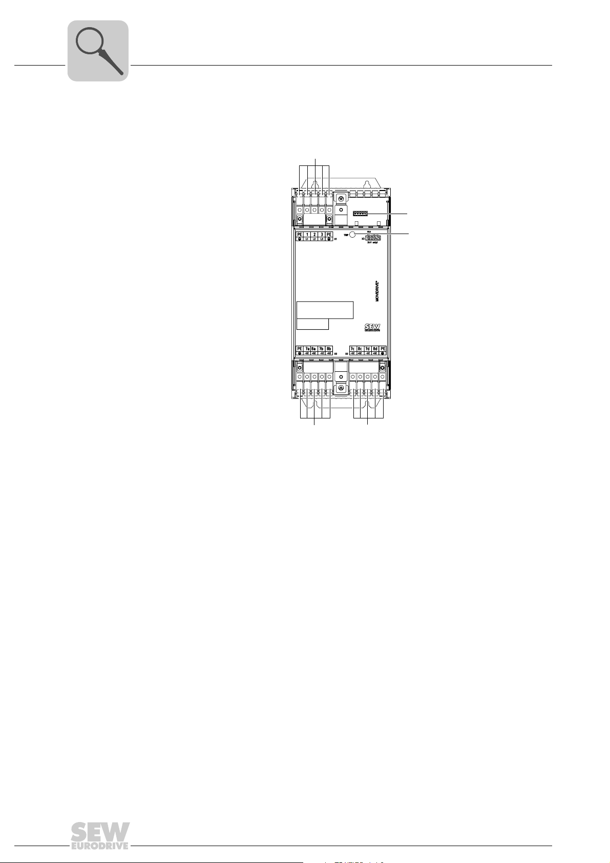
3.3 Size 2
[1]
[1]
[1]
[1]
[2] [4]
[3]
[5]
MOVIDRIVE® MDR60A0150-503-00(/L)
Unit Structure
Size 2
3
[1] PE connection
[2] X1: Power supply connection 1/L1, 2/L2, 3/L3
[3] X2: DC link connection
[4] X3: Signal terminal strip binary inputs and outputs
[5] Status LED
3908481803
Operating Instructions – MOVIDRIVE® MDR60A/61B
15
3
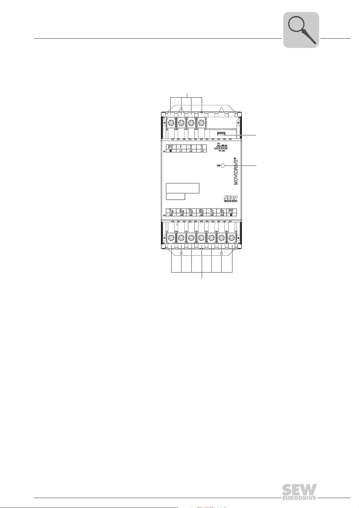
3.4 Size 3
Unit Structure
Size 3
MOVIDRIVE® MDR60A0370-503-00(/L)
[1]
[3]
[4]
[2]
[1] X1: Line connection 1/L1, 2/L2, 3/L3 and PE connection
[2] X2: DC link connection and PE connection
[3] X3: Signal terminal strip binary inputs and outputs
[4] Status LED
[2]
3908484619
16
Operating Instructions – MOVIDRIVE® MDR60A/61B
3.5 Size 4
MOVIDRIVE® MDR60A0750-503-00(/L)
[1]
Unit Structure
Size 4
[3]
[4]
3
[2]
[1] X1: Line connection 1/L1, 2/L2, 3/L3 and PE connection
[2] X2: DC link connection and PE connection
[3] X3: Signal terminal strip binary inputs and outputs
[4] Status LED
Operating Instructions – MOVIDRIVE® MDR60A/61B
17

3
3.6 Size 6
Unit Structure
Size 6
MOVIDRIVE® MDR60A1320-503-00
[8]
[4]
operation
phase failure
SKS
1+3
overtemperature
overcurrent/UcE
off/collective error
reset
2
[1]
[7]
[4]
-
L1
L2
L3
[3]
[2]
[1] PE connection
[2] line connection 1/L1, 2/L2, 3/L3
[3] Connection for DC link coupling -U
Z
+U
Z
[4] Terminal strip SKS (do not wire!)
[5] Signal terminal strip binary inputs and outputs
[6] Inhibit input A1/A2
[7] Status LED
[8] Voltage selection switch (internal)
X2
SKS
+
- L1L2L3
PE
[5] [6]
PE
[1]
18
Operating Instructions – MOVIDRIVE® MDR60A/61B
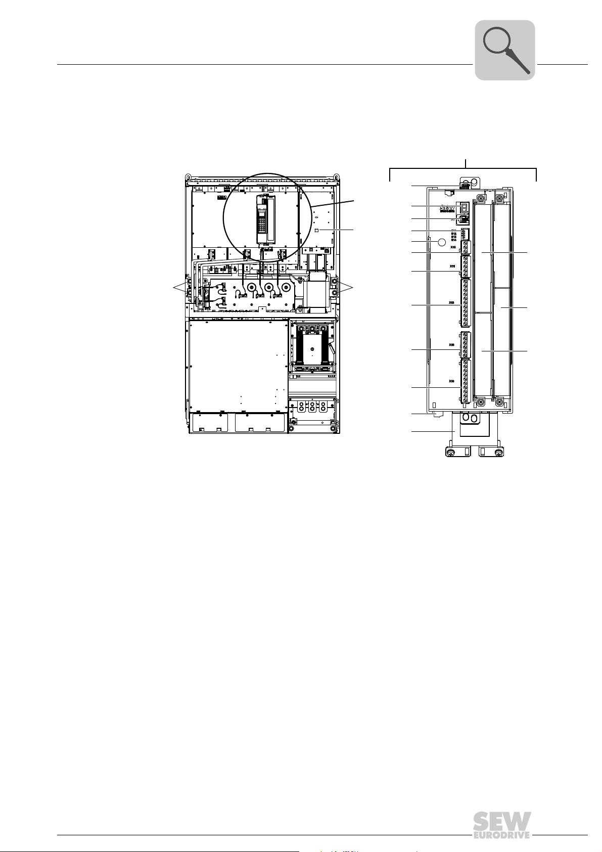
3.7 Size 7
A
[7]
[8]
[9]
[10]
[11]
[12]
[13] [4]
[5]
[6]
[14]
[15]
[16]
[17]
[19]
A
[3][3]
[2]
Unit Structure
MOVIDRIVE® MDR61B1600-503-00/L and MDR2500-503-00/L
Size 7
3
[2] DC link voltage display
[3] Connection for DC link coupling -U
[4] Fieldbus slot (cannot be used)
Z
+U
Z
[5] Extension slot (cannot be used)
[6] Encoder slot (cannot be used)
[7] Shield clamp for signal cables
[8] X17: Signal terminal strip for safety contacts for safe stop
[9] X10: Signal terminal strip binary outputs
[10] X16: Signal terminal strip binary outputs
[11] X13: Signal terminal strip terminal strip for binary inputs and RS485 interface
[12] no function
[13] X12: Signal terminal strip system bus (SBus)
[14] Grounding screw M4 × 14
[15] DIP switches S11 ... S13 (S14 no function
[16] XT: Slot for DBG60B keypad or UWS21B serial interface
[17] 7-segment display
[19] Memory card
Operating Instructions – MOVIDRIVE® MDR60A/61B
19
3
9
10
11
12
[2]
[1]
Unit Structure
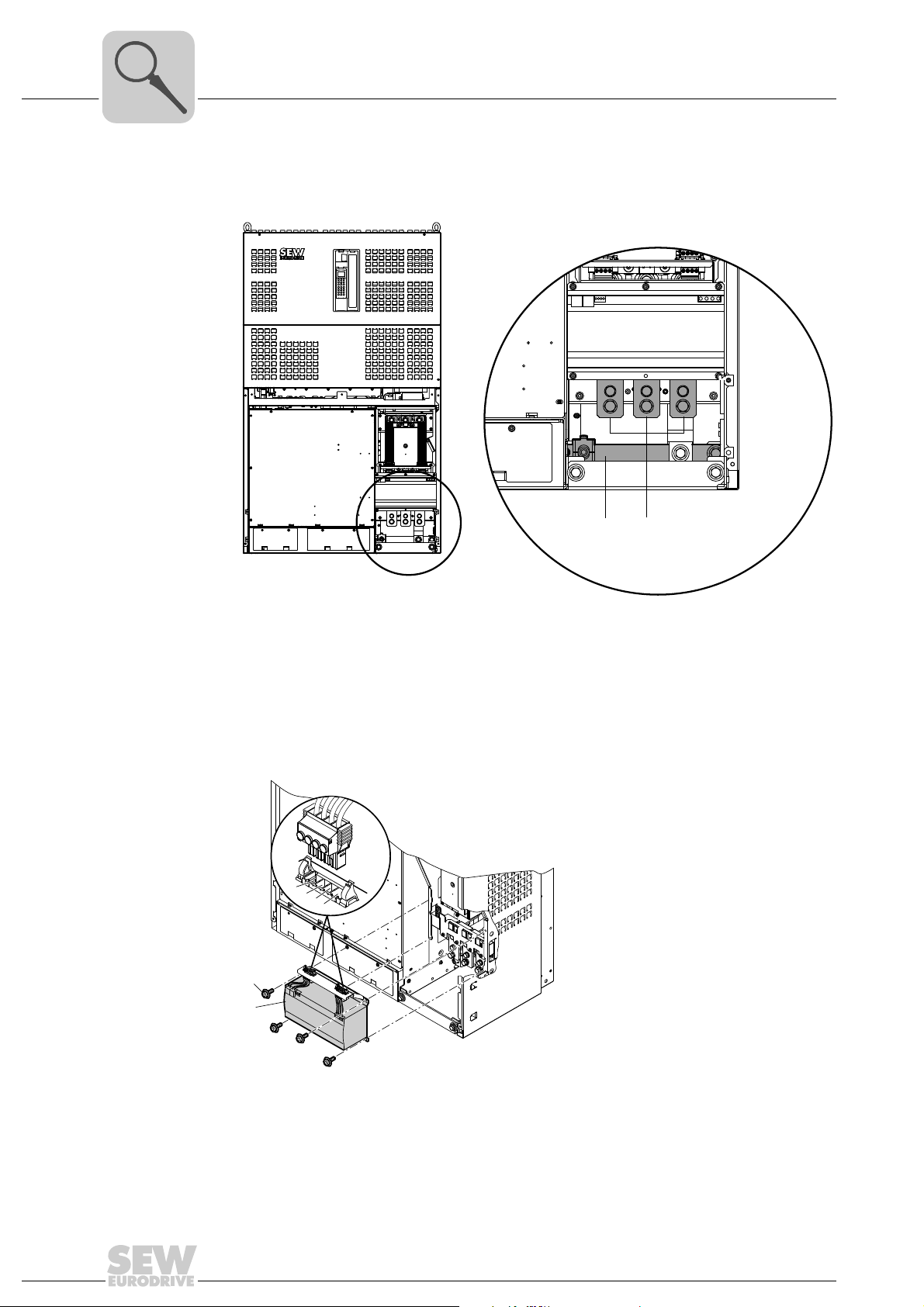
Size 7
3.7.1 MOVIDRIVE® MDR61B power connections
3.7.2 MOVIDRIVE
[1] PE connection rail (thickness = 10 mm)
[2] X1: Power supply connection 1/L1, 2/L2, 3/L3
®
MDR61B switched-mode power supply unit
[1] [2]
[1] DC power supply unit
20
[2] Screw
Operating Instructions – MOVIDRIVE® MDR60A/61B

Installation (MDR60A0150/0370/0750 and MDR61B1600/2500)
Installation notes
4 Installation (MDR60A0150/0370/0750 and MDR61B1600/2500)
This chapter illustrates the installation of the following regenerative power supply units:
•MOVIDRIVE
•MOVIDRIVE
•MOVIDRIVE
•MOVIDRIVE
•MOVIDRIVE
4.1 Installation notes
• You must observe the safety notes during installation
• In order to protect the MDR60A/61B regenerative power supply unit, you have
to evaluate the ready signal (→ chapter "Startup").
• For operation with MOVIDRIVE
ply connections of the individual MOVIDRIVE
power supply! (the MOVIDRIVE
module is excepted)
®
MDR60A0150-503-00
®
MDR60A0370-503-00
®
MDR60A0750-503-00
®
MDR61B1600-503-00/L
®
MDR61B2500-503-00/L
®
MDR60A/61B, do not connect the power sup-
®
MDR60A0150-503-00 installed as a brake
®
MDX60B/61B inverters to the
4
During operation, the heat sink temperature may rise to more than 70 °C.
Risk of burns and fire.
• Choose a suitable installation location.
• Do not touch the heat sink.
4.1.1 Tightening torques
• Only use genuine connection elements. Observe the permitted tightening
torques of the power terminals for MOVIDRIVE
WARNING
®
inverters.
Operating Instructions – MOVIDRIVE® MDR60A/61B
21
4
4.1.2 Minimum clearance and mounting position
4.1.3 Separate cable ducts
Installation (MDR60A0150/0370/0750 and MDR61B1600/2500)
Installation notes
• Observe the minimum wire bending spaces in accordance with EN 61800-5-1.
• Only install the units vertically. You must not install them horizontally, tilted or upside
down.
• Ensure unobstructed cooling air supply and make sure that the units are not subjected to heated air from nearby components.
• Observe the following clearances:
• MDR60A0150/0370: Above and below at least 100 mm (3.9 in).
• MDR60A0750 and MDR61B1600/2500: Above at least 100 mm (3.9 in). With
temperature-sensitive components such as contactors or fuses, at least 300 mm
(11.8 in).
• No clearance required on the side The units can be arranged directly next to one
another.
•Route power cables and electronics cables in separate cable ducts.
4.1.4 Fuses and earth-leakage circuit breaker
• Install the input fuses at the beginning of the supply system lead after the supply
bus junction (observe the wiring diagram for basic unit, power section and brake).
• SEW-EURODRIVE recommends not to use earth-leakage circuit breakers in plants
with frequency inverters as an earth-leakage circuit breaker reduces the plant availability.
WARNING
Wrong type of earth-leakage circuit breaker installed.
Severe or fatal injuries.
The unit can cause direct current in the protective earth. If you use an earth-leakage
circuit breaker (FI) for protection in the event of direct or indirect contact, you may only
connect a type B earth-leakage circuit breaker (FI) on the supply side of the device.
4.1.5 Polarity of the DC link connections
• You must observe the correct polarity of the DC link connections. False polarity
of the DC link connections will cause irreparable damage to the connected units!
The DC link connection carries a high DC voltage (approximately 900 V). Twist the
DC link cables and only route them inside the control cabinet.
4.1.6 Connecting inverters to the MOVIDRIVE
®
MDR60A/61B regenerative power supply unit
22
• If you use cables to connect inverters to the regenerative power supply unit, you have
to connect the inverters in star connection. Make sure to consult the installation
notes in the operating instructions for the inverter.
Operating Instructions – MOVIDRIVE® MDR60A/61B
Installation (MDR60A0150/0370/0750 and MDR61B1600/2500)
Installation notes
4.1.7 Permitted mounting the braking resistors
WARNING
Non-permissible installation might lead to an accumulation of heat in the braking resistor due to reduced convection. A tripping temperature contact or an overheated
braking resistor can lead to a system standstill.
Adhere to the following minimum distances:
• About 200 mm to adjacent components and walls
• About 300 mm to above components/ceilings
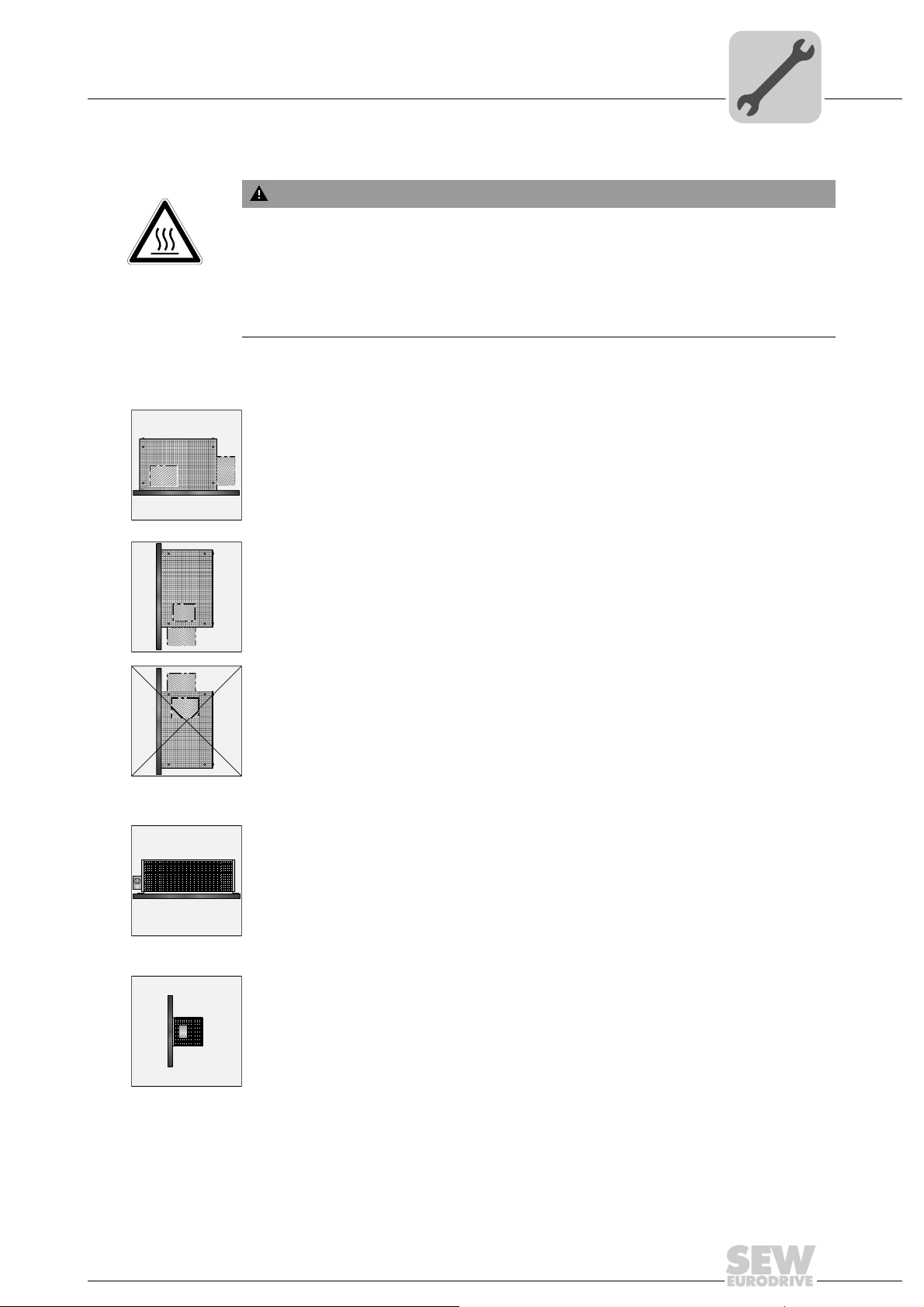
Grid resistors You must fulfill the following requirements for mounting the grid resistors:
• Permitted: Mounting on horizontal surfaces.
4
• Permitted: Mounting on vertical surfaces with terminals pointing downwards when
there is a perforated sheet at the top.
• Not permitted: Mounting on vertical surfaces with terminals pointing upwards, to the
right or left. (The connection terminals can be placed within the steel grid, where appropriate. Ensure the proper position of connection terminals also in this case).
Wire resistors You must fulfill the following requirements for mounting the wire resistors:
• Permitted: Mounting on horizontal surfaces.
• Permitted: Mounting on vertical surfaces when there is a perforated sheet at the top
or connection terminals at the bottom
Operating Instructions – MOVIDRIVE® MDR60A/61B
23
4
4.1.8 Connection of braking resistors
Installation (MDR60A0150/0370/0750 and MDR61B1600/2500)
Installation notes
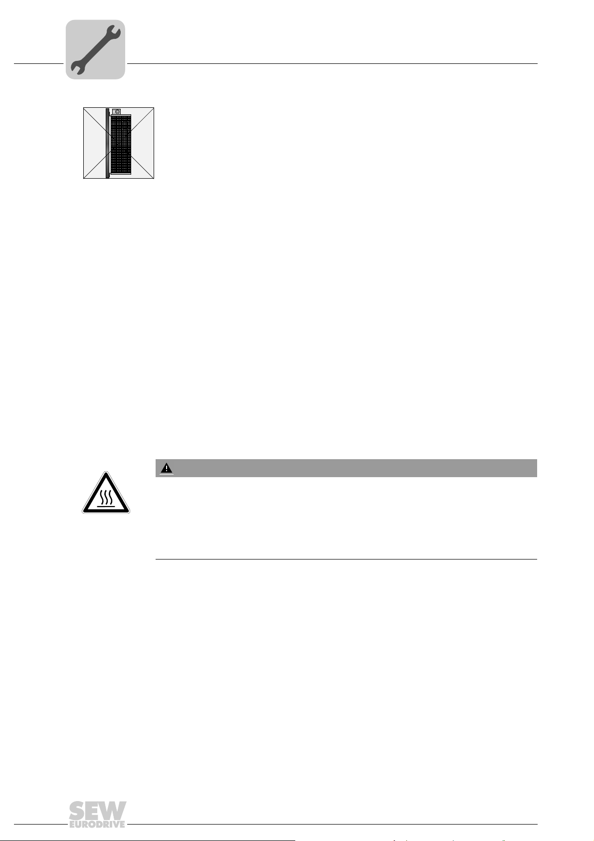
• Not permitted: Mounting on vertical surfaces when the connection terminals are at
the top.
• Use two tightly twisted leads or a 2-core shielded power cable. Cable cross sec-
tion according to trip current I
to at least V
• Protect the braking resistor (except for BW90-P52B) using a bimetallic relay (→ wiring diagram for basic unit, power section and brake). Set the trip current according
to the technical data of the braking resistor. SEW-EURODRIVE recommends
using an overcurrent relay from trip class 10 or 10A in accordance with EN 60947-4-
1.
• For braking resistors of the BW...-T / BW...-P series, the integrated temperature
switch/overcurrent relay can be connected using a 2-core shielded cable as an
alternative to a bimetallic relay.
• Flat-type braking resistors have internal thermal overload protection (fuse which
cannot be replaced). Install the flat-type braking resistors together with the appro-
priate touch guard.
of F16. The rated voltage of the cable must amount
/V = 300 V / 500 V (in accordance with DIN VDE 0298).
0
F
4.1.9 Operating braking resistors
• The connection leads to the braking resistors carry a high pulsed DC voltage during
rated operation.
WARNING
The surfaces of the braking resistors get very hot when the braking resistors are
loaded with P
Risk of burns and fire.
• Choose a suitable installation location. Braking resistors are usually mounted on
top of the control cabinet.
• Do not touch the braking resistors.
.
N
24
Operating Instructions – MOVIDRIVE® MDR60A/61B
Installation (MDR60A0150/0370/0750 and MDR61B1600/2500)
4.1.10 EMC-compliant installation
• All cables except for the supply system lead must be shielded. As an alternative to
the shielding, the option HD.. (output choke) can be used for the motor cable to
achieve the emitted interference limit values. .
NF 600
L1 L2 L3
L1 L2 L3
MOVIDRIVE® B
UVW
Installation notes
4
UVW
HD005
2394134795
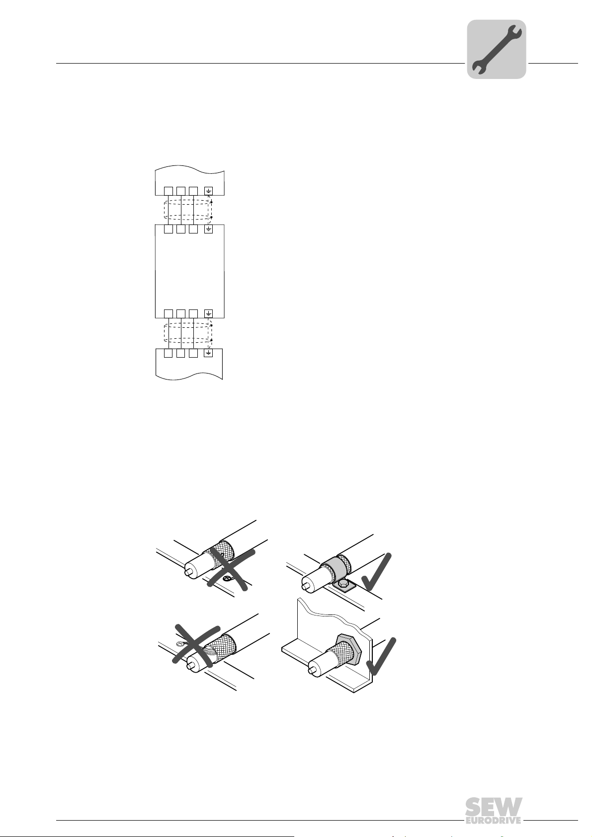
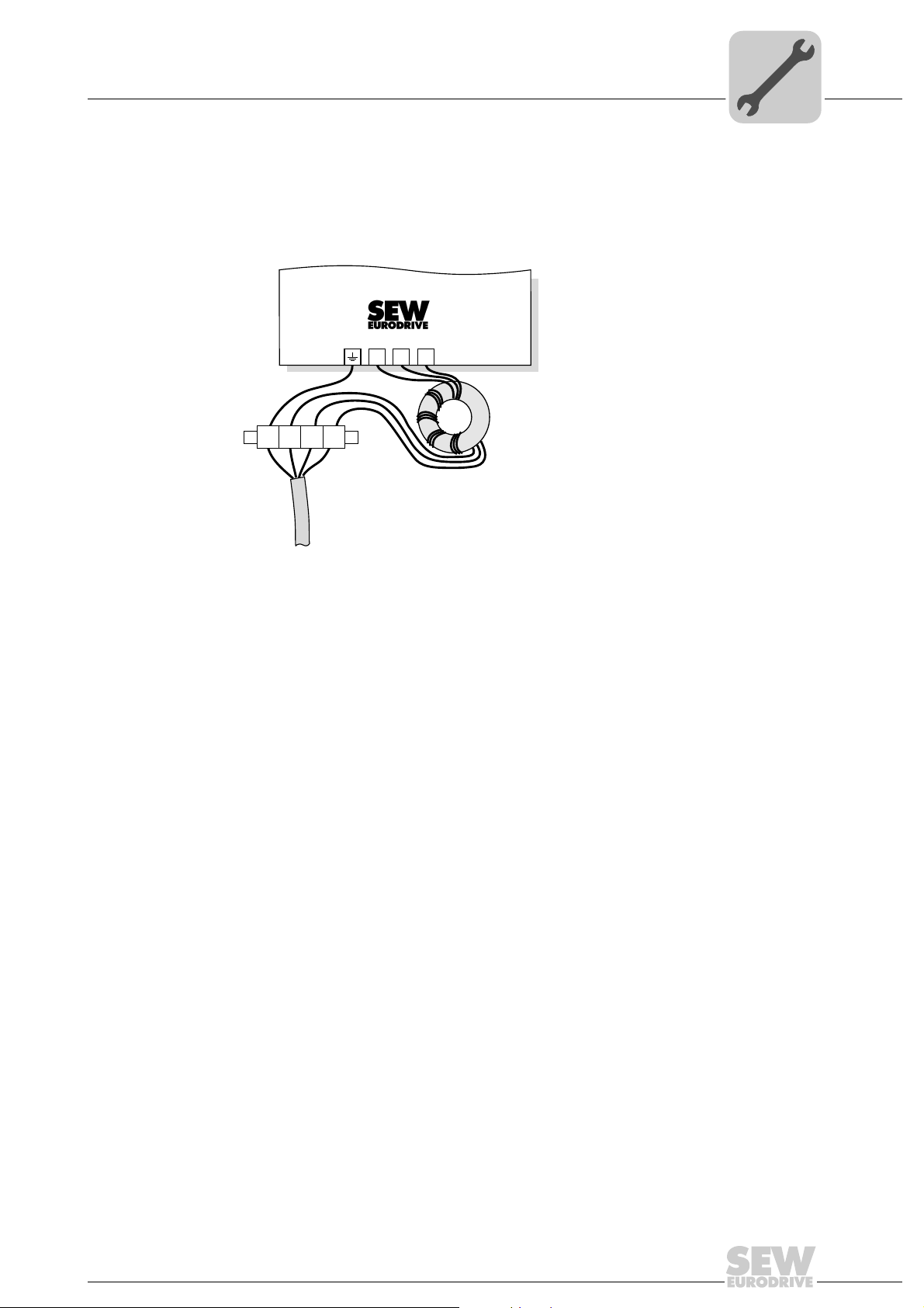
Shielded cables
• When using shielded motor cables, e.g. prefabricated motor cables from SEW-EURODRIVE, you must keep the unshielded conductors between the shield and
connection terminal of the inverter as short as possible.
• Apply the shield by the shortest possible route and make sure it is grounded
over a wide area at both ends. Ground one end of the shield using an interference
suppression capacitor (220 nF/50 V) to avoid ground loops. If using double-shielded
cables, ground the outer shield on the inverter end and the inner shield at the other
end.
Correct shield connection using metal clamp (shield clamp) or cable gland
Operating Instructions – MOVIDRIVE® MDR60A/61B
1804841739
25
4
Installation (MDR60A0150/0370/0750 and MDR61B1600/2500)
Installation notes
• You can also use earthed sheet-metal ducts or metal pipes to shield the cables.
Route the power and signal cables separately.
• Ground the inverter and all additional units to ensure high-frequency compati-
bility (wide area, metal-on-metal contact between the unit housing and ground, e.g.
unpainted control cabinet mounting panel).
INFORMATION
•MOVIDRIVE® B is a product with restricted availability in accordance with EN
61800-3. It may cause EMC interference. In this case, it is recommended for the
operator to take suitable measures.
• For detailed information on EMC compliant installation, refer to the publication
"Electromagnetic Compatibility in Drive Engineering" from SEW-EURODRIVE.
NF.. line filter • With the NF.. line filter option, the MOVIDRIVE
supply unit size 2, 3, and 7 can meet the requirements of limit value class C2.
• Do not switch between the line filter and the MOVIDRIVE
tive power supply unit.
• Install the line filter close to the regenerative power supply unit but outside the
minimum clearance for cooling.
• Keep the length of the cable between the line filter and regenerative power sup-
ply unit to an absolute minimum, and never more than 400 mm. Unshielded,
twisted cables are sufficient. Use unshielded cables for the supply system connection as well.
Interference emission category
Compliance with category C2 according to EN 61800-3 has been tested in a CE typical
drive system. SEW-EURODRIVE can provide detailed information on request.
NOTICE
This product can cause high-frequency interferences in residential areas which can require measures for interference suppression.
®
MDR60A/61B regenerative power
®
MDX60A/61B regenera-
26
Operating Instructions – MOVIDRIVE® MDR60A/61B
Installation (MDR60A0150/0370/0750 and MDR61B1600/2500)
-
Installation notes
HD... output choke • Install the output choke close to the inverter but outside the minimum clearance
for cooling.
• For HD001 ... HD003: Route all three phases (U, V, W) of the motor cable [1]
through the output choke. To achieve a higher filter effect, do not route the PE
conductor through the output choke.
4
MOVIDRIVE
UVWPE
[1]
Connection of output choke HD001 – HD003
®
X2:
UVW
n=5
[1] Motor cable
HD001
HD003
1804844811
Operating Instructions – MOVIDRIVE® MDR60A/61B
27
4
[1]
4x [2]
< 60°
> 60°
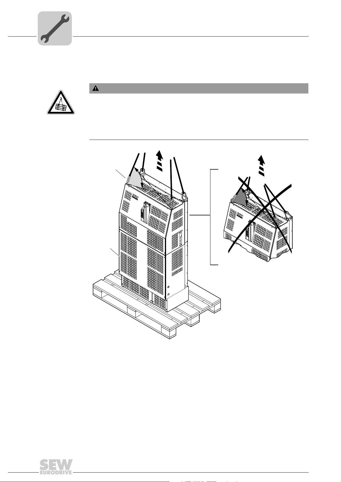
4.1.11 Installation notes for size 7
Installation (MDR60A0150/0370/0750 and MDR61B1600/2500)
Installation notes
MOVIDRIVE
only use these 4 lifting eyes [2] for installation.
Suspended load.
Danger of fatal injury if the load falls.
• Do not stand under the suspended load.
• Secure the danger zone.
• Always use all 4 lifting eyes.
• Align the lifting eyes with the direction of tension
®
units size 7 (1600 - 2500) have 4 fixed eyebolts [2] for transport. You may
WARNING
28
2077398155
[1] Installed front cover
[2] 4 lifting eyes
Operating Instructions – MOVIDRIVE® MDR60A/61B
Installation (MDR60A0150/0370/0750 and MDR61B1600/2500)
4.2 Information regarding UL
4.2.1 Power terminals
•MOVIDRIVE
use copper cables with a rated thermal value of 60/75 °C.
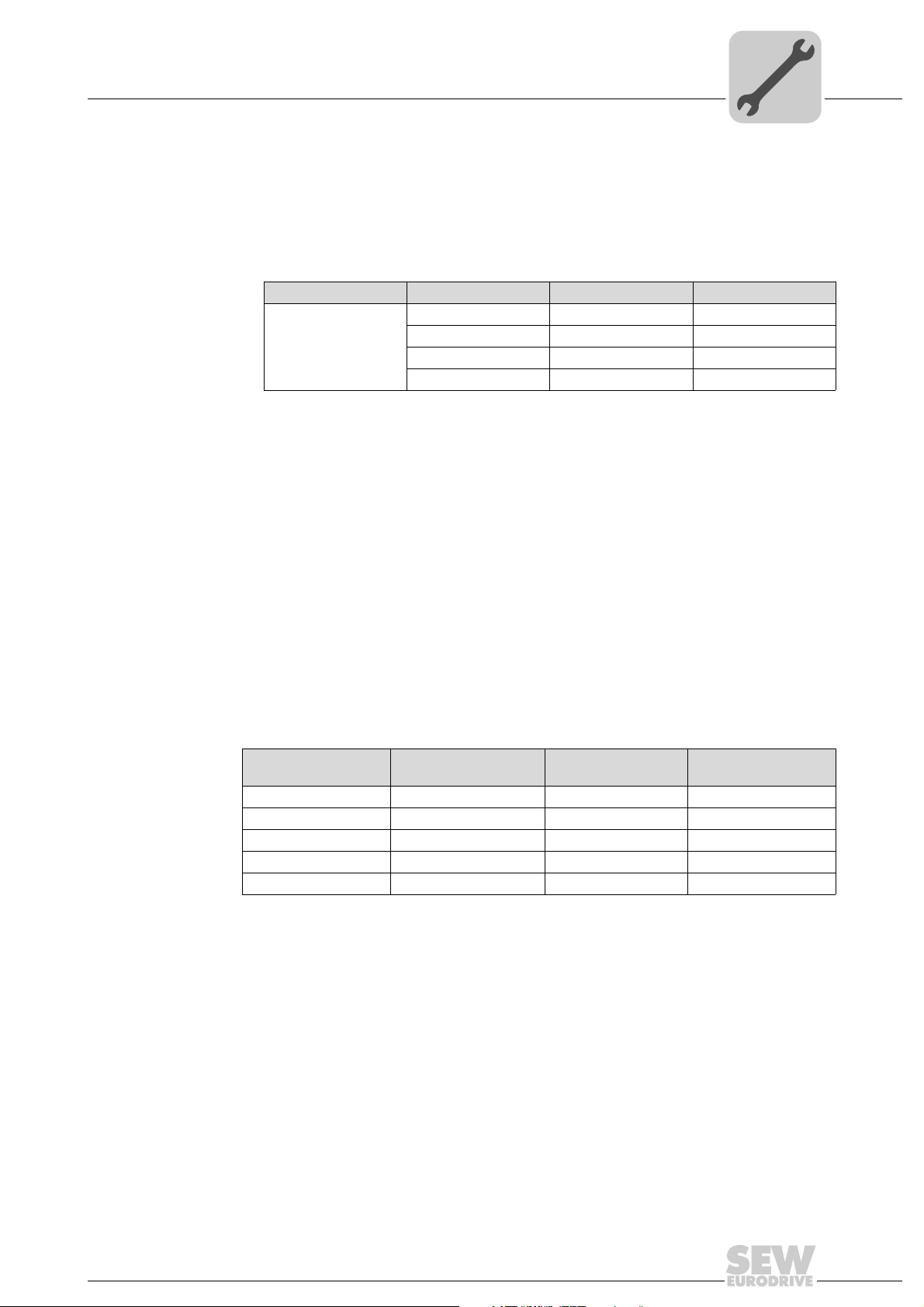
• Tighten terminals to in-lbs (Nm) as follows:
MOVIDRIVE® Size in-lbs Nm
MDR60A/61B 2 16 1.8
4.2.2 Short circuit current rating
• Suitable for the use in current circuits with a maximum short circuit current of 200000
A:
– MOVIDRIVE
they are installed with the corresponding MOVIDRIVE
Max. voltage is limited to 500 V.
®
Information regarding UL
MDR60A0150 – 0750 and MOVIDRIVE® MDR61B1600 – 2500: Only
3313.5
4 120 14
7 620 70
®
MDR60A0150 – 0750 and MOVIDRIVE® MDR61B1600 – 2500 if
®
inverter.
4
4.2.3 Branch circuit protection
Integral solid state short circuit protection does not provide branch circuit protection.
Branch circuit protection must be provided in accordance with the National Electrical
Code and any additional local codes.
The tables below list the permitted maximum fusing.
MOVIDRIVE
MDR60A/61B
®
MOVIDRIVE® MDR60A/61B
0150 AC 200000 A AC 500 V AC 50 A / 600 V
0370 AC 200000 A AC 500 V AC 100 A / 600 V
0750 AC 200000 A AC 500 V AC 175 A / 600 V
1600 AC 200000 A AC 500 V AC 400 A / 600 V
2500 AC 200000 A AC 500 V AC 600 A / 600 V
1) If the MOVIDRIVE® MDR60A/61B regenerative power supply unit is installed with the corresponding
MOVIDRIVE
®
inverter.
Max. line short circuit
1)
current
Max. line voltage Max. fuse rating
Operating Instructions – MOVIDRIVE® MDR60A/61B
29
4
4.2.4 Ambient temperature
Installation (MDR60A0150/0370/0750 and MDR61B1600/2500)
Information regarding UL
The units are suitable for an ambient temperature of 40 °C, max. 60 °C with derated output current.
®
MOVIDRIVE
than 40 °C, the output current should be derated 3.0 % per °C between 40 °C and 60 °C.
MOVIDRIVE
40 °C, the output current should be derated 2.5% per °C between 40 °C and 50 °C, and
3% per °C between 50 °C and 60 °C.
MDR60A0150 – 0750: To determine the output current rating at higher
®
MDR61B1600 – 2500: To determine output current rating at higher than
INFORMATION
• Use only tested units with a limited output voltage (U
output current (I
• UL certification does not apply to operation in voltage supply systems with a
non-grounded star point (IT systems).
= 8 A) as an external DC 24 V voltage source.
max
= DC 30 V) and limited
max
30
Operating Instructions – MOVIDRIVE® MDR60A/61B
 Loading...