

SEW DRC.-...-DAC Operating Instructions Manual
Drive Technology \ Drive Automation \ System Integration \ Services
Operating Instructions
Electronic Motor
DRC.-...-DAC
Direct AS-Interface Communication
Edition 02/2012 19376014 / EN

SEW-EURODRIVE—Driving the world

Contents
Contents
1 General Information ............................................................................................ 6
1.1 Use of this documentation .......................................................................... 6
1.2 Structure of the safety notes ....................................................................... 6
1.3 Rights to claim under limited warranty ........................................................ 7
1.4 Exclusion of liability..................................................................................... 7
1.5 Copyright..................................................................................................... 7
1.6 Product names and trademarks.................................................................. 7
2 Safety Notes ........................................................................................................ 8
2.1 General Information .................................................................................... 8
2.2 Target group ............................................................................................... 8
2.3 Designated use ........................................................................................... 9
2.4 Other applicable documentation ............................................................... 9
2.5 Transportation, storage ............................................................................. 9
2.6 Installation................................................................................................. 10
2.7 Electrical connection ................................................................................. 10
2.8 Safe disconnection.................................................................................... 10
2.9 Operation .............................................................................................. 11
3 Unit Structure .................................................................................................... 12
3.1 DRC drive unit ........................................................................................ 12
3.2 Cable entry positions .............................................................................. 13
3.3 Example nameplate and type designation of drive units ........................ 14
3.4 Electronics ............................................................................................ 15
3.5 Example nameplate and type designation of electronics ...................... 18
3.6 DRC drive units in ASEPTIC / ASEPTIC
4 Mechanical Installation..................................................................................... 22
4.1 Installation notes ................................................................................... 22
4.2 Required tools and resources ................................................................... 22
4.3 Installation requirements........................................................................... 23
4.4 Setting up the drive unit ............................................................................ 24
4.5 Tightening torques ............................................................................... 27
4.6 Drive units with optional ASEPTIC / ASEPTIC
5 Electrical Installation ........................................................................................ 36
5.1 Installation planning considering EMC aspects .................................... 36
5.2 Installation instructions.............................................................................. 38
5.3 Terminal assignment .............................................................................. 46
5.4 Connecting DRC drive units ................................................................... 48
5.5 Cable routing and shielding .................................................................... 49
5.6 EMC cable glands ................................................................................. 53
5.7 Plug connectors .................................................................................... 54
5.8 Plug connector assignment .................................................................. 58
5.9 Assignment of optional plug connectors ............................................... 59
5.10 PC connection ..................................................................................... 69
plus
design ............................. 20
plus
design ...................... 30
Operating Instructions – Electronic Motor DRC.-..-DAC
3

Contents
6 Startup................................................................................................................ 70
6.1 Startup notes ......................................................................................... 70
6.2 Lifting applications .................................................................................. 71
6.3 Prerequisties for startup ........................................................................ 71
6.4 Description of control elements ........................................................... 72
6.5 Description of DIP switches .................................................................. 74
6.6 Startup with binary slave GLK30A in "Easy mode" ............................. 76
6.7 Startup with binary slave GLK30A in "Expert mode" ............................ 80
6.8 Assigning slave address with hand-held programming device
(GLK30A) ............................................................................................ 85
6.9 Startup with double slave GLK31A ...................................................... 87
7 Operation of MOVITOOLS
7.1 About MOVITOOLS
7.2 First steps ................................................................................................ 95
7.3 Connection mode...................................................................................... 97
7.4 SBus (CAN) communication via interface adapter ................................. 99
7.5 Executing functions of the units .............................................................. 103
8 Parameters ................................................................................................... 105
8.1 Overview of parameters of the command PCB ...................................... 105
8.2 Overview of power section parameters ................................................. 109
8.3 Description of command PCB parameters.............................................. 118
8.4 Description of power section parameters................................................ 127
9 Communication with AS-Interface Double Slave GLK31A ..................... 146
9.1 Functional description ............................................................................. 146
9.2 Function modules.................................................................................... 148
9.3 Transmitting individual parameters via AS-Interface .............................. 154
10 Operation ..................................................................................................... 177
10.1 Manual operation with MOVITOOLS
10.2 Local mode ............................................................................................ 181
10.3 Releasing the brake without drive enable signal ................................ 182
®
MotionStudio .................................................. 94
®
MotionStudio .......................................................... 94
®
MotionStudio .......................... 177
11 Service ............................................................................................................. 186
11.1 Malfunctions of the mechanical DRC drive ........................................... 186
11.2 Evaluating error messages ................................................................. 187
11.3 Switch-off responses ............................................................................. 188
11.4 Reset of error messages .................................................................. 188
11.5 Description of status and operating displays ...................................... 189
11.6 Error table ........................................................................................... 192
11.7 AS-Interface bus monitor ....................................................................... 195
11.8 Unit replacement ................................................................................. 196
11.9 SEW-EURODRIVE Service ................................................................... 197
11.10 Shutdown ............................................................................................ 198
11.11 Storage ................................................................................................... 198
11.12 Extended storage .................................................................................... 198
11.13 Disposal ............................................................................................... 199
4
Operating Instructions – Electronic Motor DRC.-..-DAC

Contents
12 Inspection and Maintenance .......................................................................... 200
12.1 Determining the operating hours ......................................................... 200
12.2 Inspection and maintenance intervals ................................................... 201
12.3 Inspection and maintenance work .......................................................... 202
13 Technical Data and Dimension Sheets ......................................................... 204
13.1 Technical data ..................................................................................... 204
13.2 Braking resistors ................................................................................... 208
13.3 Technical data of the brake ................................................................... 220
13.4 ASEPTIC / ASEPTIC
13.5 Surface protection ................................................................................. 222
13.6 Screw fittings........................................................................................... 224
13.7 Dimension drawings ........................................................................... 225
14 EC Declaration of Conformity ...................................................................... 228
15 Address List .................................................................................................... 229
Index................................................................................................................. 240
plus
variants ......................................................... 221
Operating Instructions – Electronic Motor DRC.-..-DAC
5
1
General Information
Use of this documentation
1 General Information
Electronic Motor DRC.-..-DAC
1.1 Use of this documentation
The documentation is an integral part of the product and contains important information
on operation and service. The documentation is written for all employees who assemble,
install, start up, and service this product.
The documentation must be accessible and legible. Make sure that persons responsible
for the system and its operation, as well as persons who work independently on the unit,
have read through the documentation carefully and understood it. If you are unclear
about any of the information in this documentation, or if you require further information,
contact SEW-EURODRIVE.
1.2 Structure of the safety notes
1.2.1 Meaning of the signal words
The following table shows the grading and meaning of the signal words for safety notes,
notes on potential risks of damage to property, and other notes.
Signal word Meaning Consequences if disregarded
DANGER Imminent danger Severe or fatal injuries
WARNING Possible dangerous situation Severe or fatal injuries
CAUTION Possible dangerous situation Minor injuries
NOTICE Possible damage to property Damage to the drive system or its
INFORMATION Useful information or tip:
Simplifies the handling of the
drive system.
environment
1.2.2 Structure of the section-related safety notes
Section-related safety notes do not apply to a specific action, but to several actions
pertaining to one subject. The used symbols indicate either a general or a specific
hazard.
This is the formal structure of a section-related safety note:
SIGNAL WORD
Type and source of danger.
Possible consequence(s) if disregarded.
• Measure(s) to prevent the danger.
1.2.3 Structure of the embedded safety notes
Embedded safety notes are directly integrated in the instructions just before the description of the dangerous action.
This is the formal structure of an embedded safety note:
• SIGNAL WORD Nature and source of hazard.
Possible consequence(s) if disregarded.
– Measure(s) to prevent the danger.
6
Operating Instructions – Electronic Motor DRC.-..-DAC

Rights to claim under limited warranty
1.3 Rights to claim under limited warranty
A requirement of fault-free operation and fulfillment of any rights to claim under limited
warranty is that you adhere to the information in the documentation. Read the documentation before you start working with the unit!
1.4 Exclusion of liability
You must comply with the information contained in this documentation to ensure safe
operation and to achieve the specified product characteristics and performance
features. SEW-EURODRIVE assumes no liability for injury to persons or damage to
equipment or property resulting from non-observance of these operating instructions. In
such cases, any liability for defects is excluded.
1.5 Copyright
© 2012 – SEW-EURODRIVE. All rights reserved.
Unauthorized duplication, modification, distribution or any other use of the whole or any
part of this documentation is strictly prohibited.
General Information
1
1.6 Product names and trademarks
All brands and product names in this documentation are trademarks or registered trademarks of their respective titleholders.
Operating Instructions – Electronic Motor DRC.-..-DAC
7

2
Safety Notes
General Information
2 Safety Notes
2.1 General Information
The following basic safety notes must be read carefully to prevent injury to persons and
damage to property. The operator must ensure that the basic safety notes are read and
adhered to. Ensure that persons responsible for the system and its operation, as well as
persons who work independently on the unit, have read through the operating
instructions carefully and understood them. If you are unclear about any of the information in this documentation, or if you require further information, please contact SEWEURODRIVE.
Never install damaged products or take them into operation. Submit a complaint to the
shipping company immediately in the event of damage.
During operation, DRC drive units can have live, bare and movable or rotating parts as
well as hot surfaces, depending on their degree of protection.
Removing covers without authorization, improper use as well as incorrect installation or
operation may result in severe injuries to persons or damage to property.
Refer to the documentation for additional information.
2.2 Target group
Only qualified electricians are authorized to install, start up or service the units or
correct unit faults (observing IEC 60364 or CENELEC HD 384 or DIN VDE 0100 and
IEC 60664 or DIN VDE 0110 as well as national accident prevention guidelines).
Qualified electricians in the context of these basic safety notes are all persons familiar
with installation, assembly, startup and operation of the product who possess the
necessary qualifications.
All persons involved in any other work, such as transportation, storage, operation and
disposal, must be trained appropriately.
8
Operating Instructions – Electronic Motor DRC.-..-DAC

2.3 Designated use
DRC drive units are components intended for installation in electrical systems or machines.
In case of installation in machines, taking the DRC drive units into operation (i.e. start of
designated operation) is prohibited until it is determined that the machine meets the requirements stipulated in EC Directive 2006/42/EC (Machinery Directive).
Startup (i.e. the start of designated use) is only permitted under observance of EMC
directive 2004/108/EC (EMC Directive).
DRC drive units comply with the regulations of the Low Voltage Directive 2006/95/EC.
The standards given in the declaration of conformity are applied to the DRC drive units.
You must observe the technical data and information on the connection requirements
as provided on the nameplate and in the documentation.
2.3.1 Safety functions
DRC drive units may not
and expressly permitted.
Safety Notes
Designated use
perform safety functions unless these functions are described
2
2.3.2 Lifting applications
DRC drive units are not designed for use as safety devices in lifting applications.
2.4 Other applicable documentation
Note also the following documentation:
• "DRC Gearmotors" catalog
• Operating instructions for the gear unit (only for DRC gearmotors)
You can download or order these publications on the Internet (http://www.sew-euro-
drive.com under the heading "Documentation").
2.5 Transportation, storage
You must observe the notes on transportation, storage and proper handling. Comply
with the requirements for climatic conditions stated in chapter "Technical Data". Tighten
installed eyebolts securely. They are designed for the weight of the DRC drive unit. Do
not attach any additional loads. Use suitable, sufficiently rated handling equipment (e.g.
rope guides) if required.
Operating Instructions – Electronic Motor DRC.-..-DAC
9

2
Safety Notes
Installation
2.6 Installation
2.7 Electrical connection
The units must be installed and cooled according to the regulations and specifications
in the corresponding documentation.
Protect the DRC drive units from improper strain.
The following applications are prohibited unless explicitly permitted:
• Use in potentially explosive atmospheres.
• Use in areas exposed to harmful oils, acids, gases, vapors, dust, radiation, etc.
• Use in non-stationary applications that are subject to mechanical vibration and shock
loads as stated in the documentation for DRC drive units.
Important: DRC drive units and corresponding mount-on parts must not protrude into
footways.
Working on live parts of DRC drive units is not permitted.
The drive is operated as a generator due to the kinetic energy of the system/machine.
Secure the output shaft against rotation before opening the wiring compartment.
Electrical installation must be carried out in compliance with pertinent regulations (e.g.
cable cross sections, fusing, protective conductor connection). For any additional information, refer to the applicable documentation.
You find notes on EMC-compliant installation, such as shielding, grounding, arrangement of filters and routing of lines, in the documentation of the DRC drive units. The
manufacturer of the system or machine is responsible for maintaining the limits established by EMC legislation.
Protective measures and protection devices must comply with the regulations in force
(e.g. EN 60204-1 or EN 61800-5-1).
2.8 Safe disconnection
DRC drive units meet all requirements for safe disconnection of power and electronics
connections in accordance with EN 61800-5-1. All connected circuits must also satisfy
the requirements for safe disconnection to ensure reliable isolation.
10
Operating Instructions – Electronic Motor DRC.-..-DAC

2.9 Operation
Safety Notes
Operation
Systems with integrated DRC drive units must be equipped with additional monitoring
and protection devices according to the applicable safety guidelines, such as the law
governing technical equipment, accident prevention regulations, etc. Additional protective measures may be necessary for applications with increased potential risk. Changes
to DRC drive units using the operating software are permitted.
Do not touch live components and power connections immediately after separation of
the DRC drive units from the supply voltage because some capacitors might still be
charged. Wait at least for 10 minutes after the supply voltage has been switched off.
The connection boxes must be closed and screwed on before the supply voltages are
connected to DRC drive units.
The unit may still be live and connected to the power supply even if the operation LEDs
and other display elements are no longer illuminated.
Mechanical blocking or internal safety functions of the unit can cause a motor standstill.
Eliminating the cause of the problem or performing a reset may result in the drive restarting automatically. If, for safety reasons, this is not permitted for the driven machine,
disconnect the unit from the supply system before correcting the error.
Caution: Danger of burns: The surface temperatures of DRC drive units can be more
than 60 °C during operation.
2
Operating Instructions – Electronic Motor DRC.-..-DAC
11
3
R..DRC1-...
R..DRC2-...
[1]
[2]
[1]
[2]
[3]
[3]
[4]
[4]
3 Unit Structure
3.1 DRC drive unit
Unit Structure
DRC drive unit
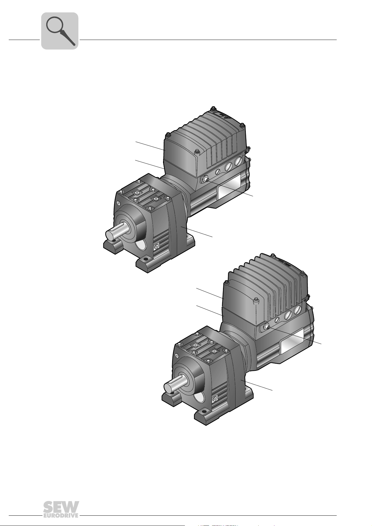
The following figure depicts drive units consisting of DRC1/DRC2 electronic motor and
R gear unit:
12
[1] Electronics cover
[2] DRC electronic motor with connection unit
[3] Gear unit (in the figure: R gear unit)
[4] AS-Interface connection
4761500555
Operating Instructions – Electronic Motor DRC.-..-DAC
3.2 Cable entry positions
RUN
NET
DRIVE
3
X
2
The DRC electronic motor generally comes equipped with the following cable entries1):
• Position X + 2 + 3
– X: 2 x M25 x 1.5 + 2 x M16 x 1.5
– 2: 2 x M25 x 1.5 + 2 x M16 x 1.5
– 3: 2 x M25 x 1.5 + 2 x M16 x 1.5
Unit Structure
Cable entry positions
3
9007203301611787
1) 1 x M16 x 1.5 reserved for pressure compensation fitting (only in conjunction with ASEPTIC/ASEPTIC
variants as well as brakemotors operated at ambient temperatures of < 20 °C)
Operating Instructions – Electronic Motor DRC.-..-DAC
plus
13
3
[1]
[2]
76646 Bruchsal/Germany
kg AMB 1845 494 1.50°C
M
A
M
BR
Ma
pk
Nm
IM
Nm
Nm
i
kW
Iso.Kl. M.L. Hz 50-60 V A
nR
r/min IP
eff%
26.000
85...0.04
TENV
87,1 IE4
1.04
156
-20...40 Made in Germany
M1CLP 220 Miner.Öl/0.65 l
1/2000
23.59 62
155
0.55 S1
(F)
380...500
65
3~IEC61800
RF47 DRC1-005-DAC-A-ECR/IV
01.1751709009.0001.11
Inverter duty VPWM
Unit Structure
Example nameplate and type designation of drive units
3.3 Example nameplate and type designation of drive units
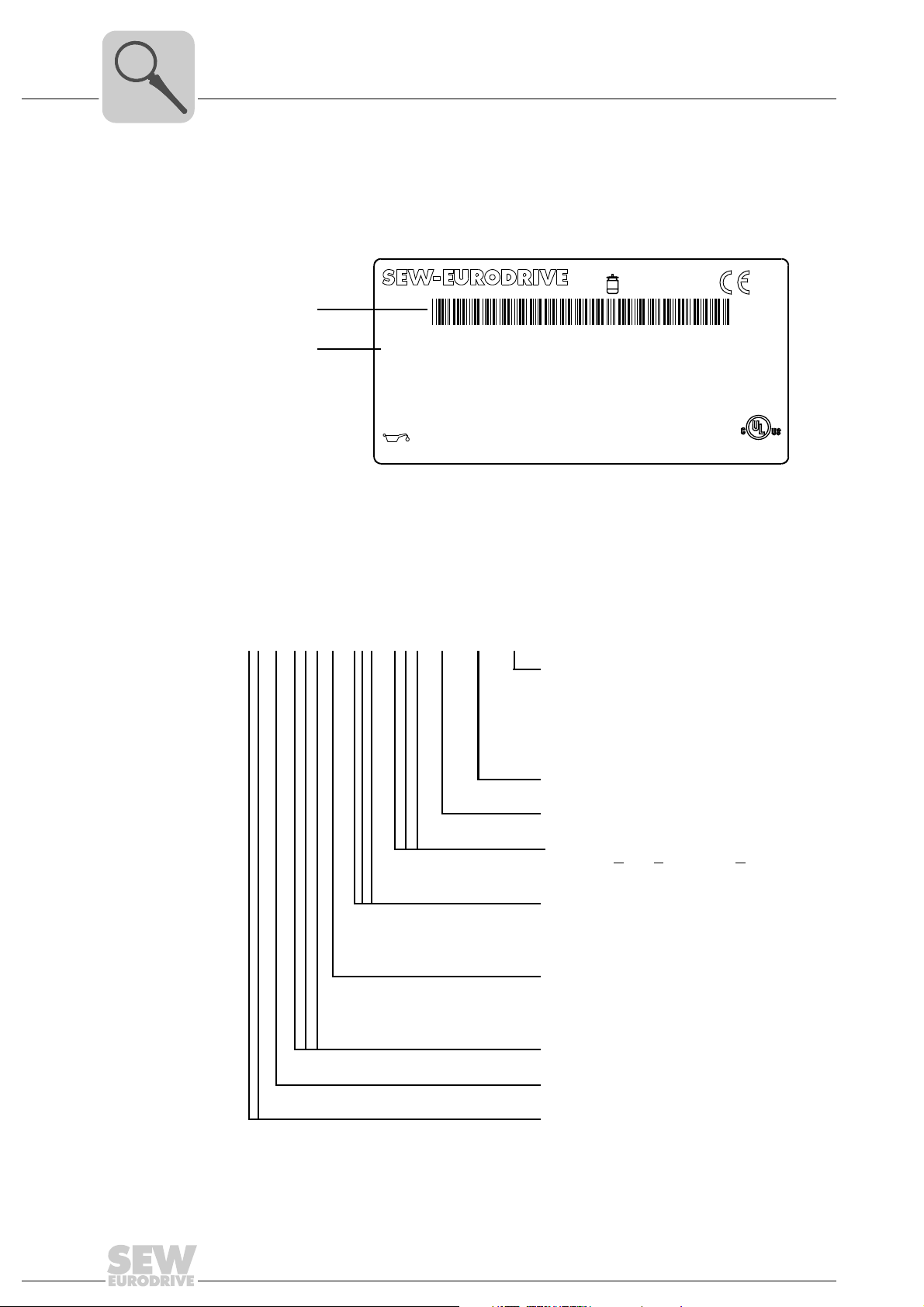
3.3.1 Nameplate
The following figure gives an example of a DRC nameplate. For the structure of the type
designation, refer to chapter "Type designation".
[1] Unique serial number
[2] The bar code on the nameplate (code 39) according to ISO/IEC 16388 represents the unique
serial number (with a period as separator).
4761948811
3.3.2 Type designation
The following table shows the type designation of the DRC drive unit:
RF 47 DRC 1 - 005 - DAC - A - ECR / IV
DRC option
IV = Plug connector
BY1C = Brake DRC1
BY2C = Brake DRC2
BW1 = Integrated braking resistor DRC1
BW2 = Integrated braking resistor DRC2
Extended control range (standard)
Version
DRC installation technology
DAC = D
irect AS-Interface Communication
Power rating
005 = 0.55 kW
015 = 1.5 kW
Electronic motor size
1 = DRC1
2 = DRC2
14
Product line
DRC = Electronic motor
Gear unit size
Gear unit series
Operating Instructions – Electronic Motor DRC.-..-DAC
3.4 Electronics
[2]
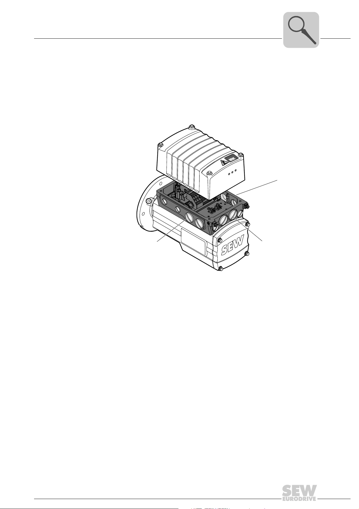
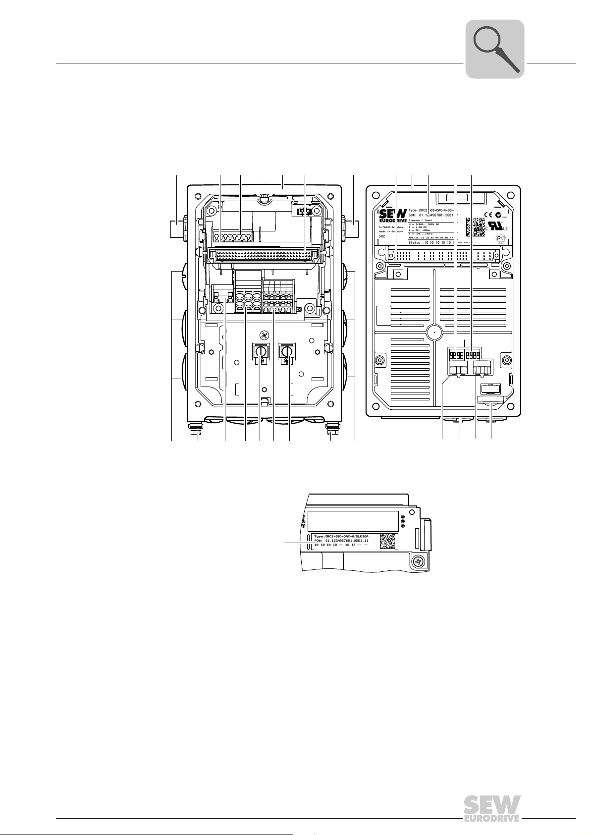
3.4.1 DRC electronics cover (inside) and connection box
The following figure shows the connection box and the bottom side of the DRC electronics cover:
Unit Structure
Electronics
3
[1] [6][5]
[14][12] [12][12]
[11]
[13]
[4][2] [3]
[12] [15]
[11]
[7]
[8][5]
[10][9]
S1 S2
1234 123 4
ON
ON
ADE04SA
ADE04SA
1234
1234
34567 34567
t1
f2 f1
[16] [17] [18] [19]
4762857739
[1] AS-Interface connection
[2] Nameplate of drive unit, see following detailed view
[3] AS-Interface terminals (wired to plug connector)
[4] Connection box
[5] Plug connector connection unit for DRC electronics cover
[6] AS-Interface sensors
[7] DRC electronics cover
[8] Electronics cover nameplate
[9] DIP switches S1/1 – S1/4
[10] DIP switches S2/1 – S2/4
[11] Cable glands
[12] Screws for PE connection
[13] Braking resistor connection
[14] Line connection L1, L2, L3
[15] Electronics terminal strips
[16] Switch t1 for integrator ramp (green)
[17] Diagnostic interface (underneath the gland)
[18] Setpoint switch f2 (white)
[19] Setpoint potentiometer f1 with screw plug
4853289611
Operating Instructions – Electronic Motor DRC.-..-DAC
15

3
3.4.2 AS-Interface option
Unit Structure
Electronics
The AS-Interface option is located on the connection board in the connection box.
DRC-DAC is available with the following AS-Interface variants:
• GLK30A binary slave
• GLK31A double slave for drive with several speed setpoints and ramps
GLK30A binary
slave
GLK31A double
slave
Connected to the AS-Interface, the GLK30A slave works like a module with 4 inputs and
4 outputs.
The cyclic output bits control the DRC-DAC inverter.
The input bits transmit the status of the drive and two additional sensor signals to the
AS-Interface master.
The acyclic parameter bits are used to select speed scaling factors.
The GLK31A option works as a double slave on the AS-Interface according to ASInterface specification 3.0.
Serial AS-Interface data transmission (analog profile) allows for writing and reading
DRC-DAC parameters and display values.
The DRC-DAC inverter is controlled via the cyclic output bits. The coding of the data bits
is specified in different function modules. The DRC-DAC inverter interprets these bits as
different control and status codes. You can switch between the function modules using
the acyclic parameter bits.
The input bits transmit the status of the drive and 2 additional sensor signals to the ASInterface master.
16
Operating Instructions – Electronic Motor DRC.-..-DAC
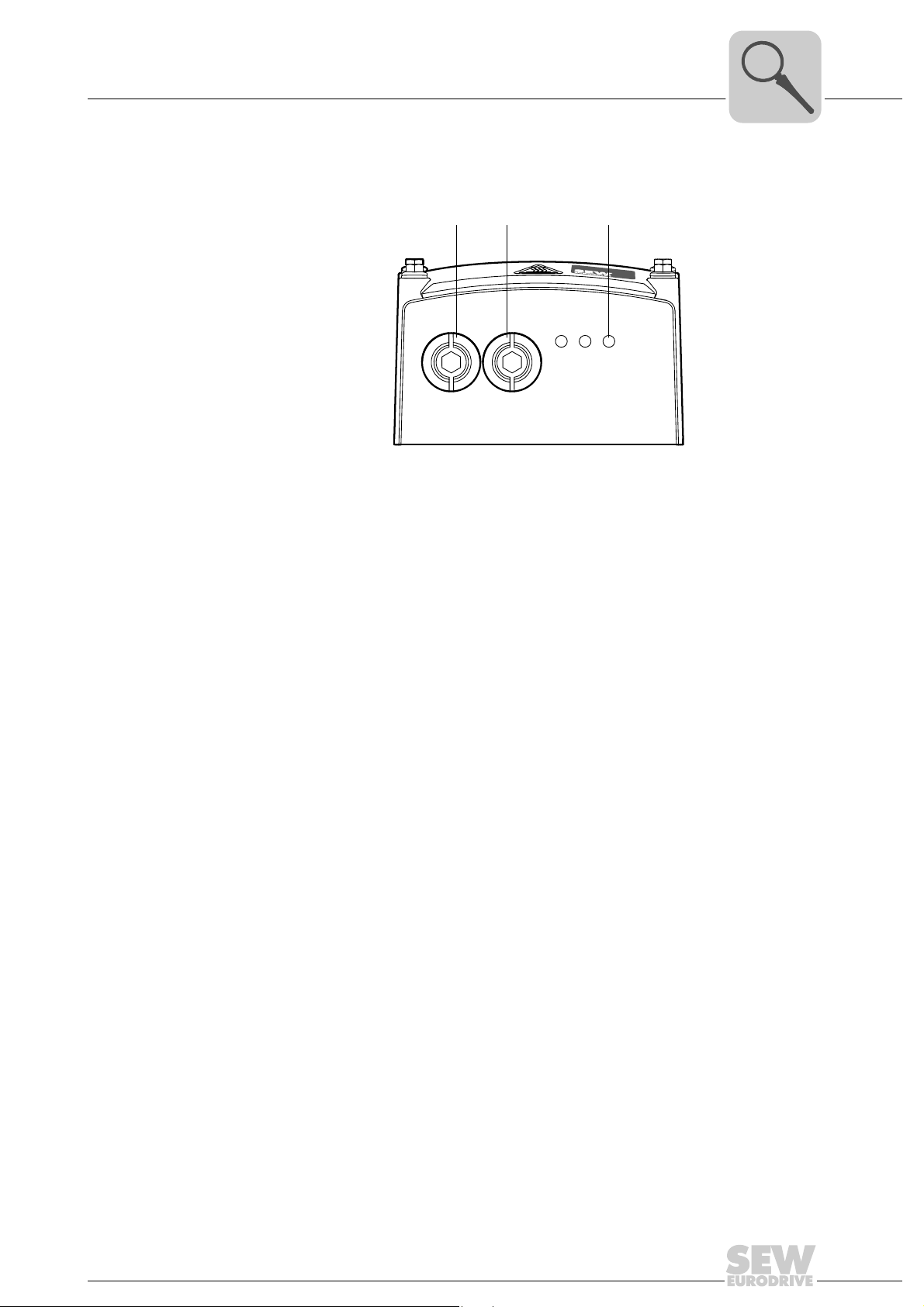
3.4.3 Electronics cover (outside)
The following figure shows the outside of the electronics cover:
[1] Setpoint potentiometer f1 (underneath the gland)
[2] Diagnostic interface (underneath the gland)
[3] Status LEDs
Unit Structure
[1] [2] [3]
NET RUN DRIVE
Electronics
3
9007201622609547
Operating Instructions – Electronic Motor DRC.-..-DAC
17
3
[1]
[2]
Unit Structure
Example nameplate and type designation of electronics
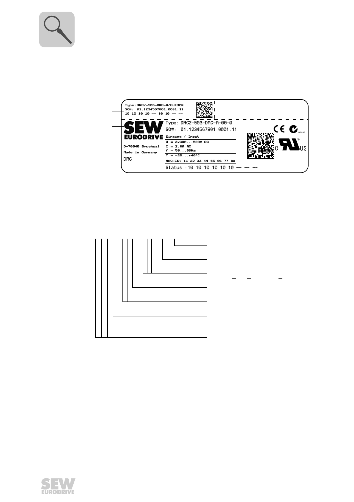
3.5 Example nameplate and type designation of electronics
3.5.1 Nameplate
The following figure gives an example of a DRC nameplate For the structure of the type
designation, refer to chapter "Type designation".
[1] Nameplate of connection unit
[2] Nameplate of electronics cover
4766269963
3.5.2 Type designation of electronics cover
The following table shows the type designation of the electronics cover:
D R C 1 – 5 0 3 – DAC – A – 00
Variant
00 = Standard
DRC version
DRC installation technology
DAC = D
Connection type
3 = 3-phase (AC)
Supply voltage
50 = AC 380 – 500 V
Size
1
2
Product line
DRC = Electronic motor
irect AS-Interface Communication
==DRC 1
DRC 2
18
Operating Instructions – Electronic Motor DRC.-..-DAC
Example nameplate and type designation of electronics
3.5.3 Type designation of connection unit
The following table shows the type designation of the connection unit:
D R C 1 – 5 0 3 – DAC – A – / GLK30A
Unit Structure
Connection unit option
GLK30A = GLK30A binary slave
GLK31A = GLK31A double slave
DRC version
DRC installation technology
DAC = D
Connection type
3 = 3-phase (AC)
Supply voltage
50 = AC 380 – 500 V
Size
1
2
Product line
DRC = Electronic motor
irect AS-Interface Communication
==DRC 1
DRC 2
3
Operating Instructions – Electronic Motor DRC.-..-DAC
19
3
MOVIGEAR
®
B
SNI
A
B
[B 2]
[B 1]
Y
X
X
Y
[A3]
[A3]
[A2]
[A1]
[A7]
[A6]
[A5]
[A4]
Unit Structure
DRC drive units in ASEPTIC / ASEPTICplus design
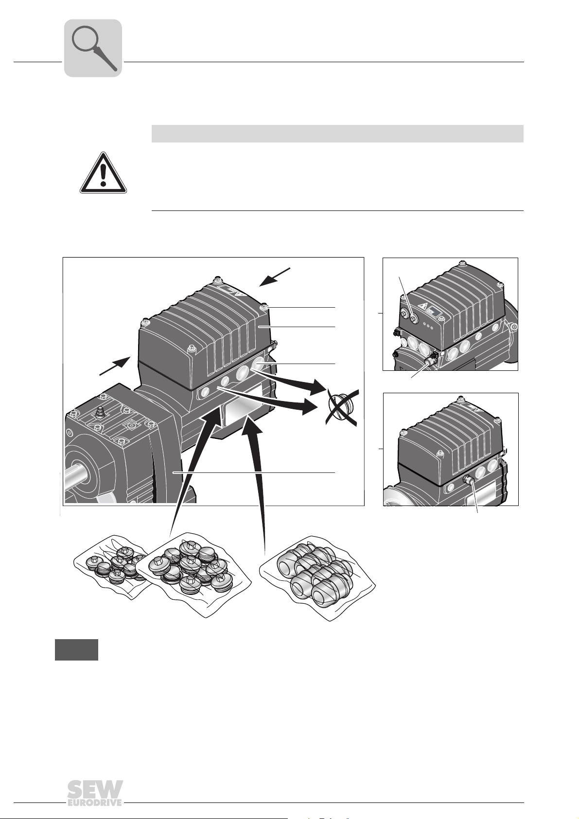
3.6 DRC drive units in ASEPTIC / ASEPTIC
NOTICE
Loss of degree of protection IP66 and incompatibility with cleaning agents.
Possible damage to property.
• To achieve degree of protection IP66 and compatibility with cleaning agents, you
have to replace the plastic screw plugs delivered as standard by suitable screw
fittings made of stainless steel.
The following picture shows the additional characteristics of DRC drive units in
ASEPTIC / ASEPTIC
plus
design:
plus
design
DRC
NET
RUN
DRIVE
All illustrations with ASEPTIC / ASEPTIC
tion) in this publication
plus
design are displayed with a shading (= HP200 surface protec-
4765682443
20
Operating Instructions – Electronic Motor DRC.-..-DAC

Unit Structure
DRC drive units in ASEPTIC / ASEPTICplus design
A Scope of delivery
[A1] Mounting screws for cover made of stainless steel
[A2] Surface protection OS2 to OS4 for ASEPTIC design / OS4 for ASEPTIC
"Technical data and dimension sheets"
[A3] The delivered plastic screw plugs must be replaced by suitable screw plugs made of stainless
steel.
[A4] Screw plugs in the electronics cover made of stainless steel
[A5] Pre-installed pressure compensation fitting (M16) with mounting positions M5, M6
[A6] Pre-installed pressure compensation fitting (M16) with mounting position M1, M2, M4, M4
plus
design, see chapter
3
Optional plug connectors (see chapter "Electrical installation") are available in connection with the
ASEPTIC / ASEPTIC
plus
version.
[A7] Features of gear units in ASEPTIC design
– Surface protection finish OS2 to OS4
Features of gear units in ASEPTIC
plus
design
– Available for gear units with solid shaft, hollow shaft with key or TorqLOC for the following gear
unit sizes: R27-87, F27-87, K37-87 and W37
– Gear unit output shaft including all retaining parts on the output shaft, such as screws, keys,
shrink disk, etc., are made of stainless steel
– If technically possible, the oil seals on the output are configured as double oil seals made from
FKM (Viton
®
)
– The breather valve of the gear units is made from stainless steel
– Surface protection finish OS4 for compatibility with common cleaning agents and disinfectants
– All surface recesses sprayed with elastic rubber compound
– All gear unit options can be selected
– All mounting positions M1 to M6 are available
B Required screw fittings
[B1] Screw plugs made of stainless steel
[B2] Cable glands made of stainless steel
1)
1)
The required screw fittings can be ordered from SEW-EURODRIVE. For an overview, refer to chapter
"Technical Data / Optional metal screw fittings".
1) Make sure to select plug seals that are compatible with the cleaning agents used
Operating Instructions – Electronic Motor DRC.-..-DAC
21
4
Mechanical Installation
Installation notes
4 Mechanical Installation
4.1 Installation notes
INFORMATION
Adhere to the safety notes during installation.
WARNING
Improper installation/disassembly of DRC drive units and mount-on components.
Risk of injury.
• Adhere to the notes about installation and disassembly.
• Before releasing shaft connections, make sure that there are no active torsional
moments present (tensions within the system).
WARNING
Risk of injury if the drive starts up unintentionally and danger of electrical voltage.
Dangerous voltages may still be present for up to 10 minutes after disconnection from
the power supply.
Severe or fatal injuries.
• Disconnect the DRC drive unit from the power supply before you start working on
the unit and secure it against unintentional reconnection to the power supply.
• Secure the output shaft against rotation.
• Wait for at least 10 minutes before removing the electronics cover.
4.2 Required tools and resources
• Set of wrenches
• Torque wrench
• Mounting device
• Compensation elements (shims and spacing rings), if necessary
• Mounting materials for output components
• Lubricant (e.g. NOCO
• Standard parts are not included in the delivery
4.2.1 Installation tolerances for shaft ends
The following table shows the permitted tolerances of shaft ends and flanges of the
DRC motor.
®
Fluid)
22
Shaft end Flanges
Diameter tolerance according to EN 50347
• ISO j6 with Ø ≤ 26 mm
• Center bore in accordance with DIN 332,
shape DR..
Operating Instructions – Electronic Motor DRC.-..-DAC
Centering shoulder tolerance in accordance
with EN 50347
• ISO j6 with Ø ≤ 250 mm

4.3 Installation requirements
Check that the following conditions have been met:
• The entries on the nameplate of the DRC unit match the voltage supply system.
• The drive is undamaged (no damage caused by transportation or storage)
• Ambient temperature according to the operating instructions, nameplate and
lubricant table in chapter "Technical data and dimension sheets / Lubricants".
• The drive must not be assembled in the following ambient conditions:
– Potentially-explosive atmosphere
– Oils
–Acids
– Gases
– Vapors
– Radiation
• For special designs: The drive is designed in accordance with the actual ambient
conditions.
• You must clean the output shafts and flange surfaces thoroughly to ensure they are
free of anti-corrosion agents, contamination or similar. Use a commercially available
solvent. Do not expose the sealing lips of the oil seals to the solvent – damage to the
material.
Mechanical Installation
Installation requirements
4
• When the drive is installed in abrasive ambient conditions, protect the output end oil
seals against wear.
Operating Instructions – Electronic Motor DRC.-..-DAC
23

4
Mechanical Installation
Setting up the drive unit
4.4 Setting up the drive unit
4.4.1 Notes
• Only install the DRC drive unit on a level, low-vibration, and torsionally rigid support
• Observe the mounting position specified on the motor nameplate.
• Thoroughly remove any anti-corrosion agent from the shaft end. Use a commercially
• Align the motor carefully to avoid placing any unacceptable strain on the motor
• Do not jolt or hammer the shaft end.
• Ensure that cooling air supply is unobstructed and that air discharged by other units
• Balance components that were subsequently mounted to the shaft with a half key
• Use suitable cable glands for the supply leads (use reducing adapters if necessary).
• Seal the cable entry properly.
structure.
available solvent. Do not allow the solvent to penetrate the bearings and shaft seals
– this could damage the material.
shafts. Observe the permitted overhung and axial loads specified in the "DRC Gearmotors" catalog.
does not influence cooling.
(output shafts are balanced with a half key).
• Thoroughly clean the sealing surfaces of the DRC cover before re-assembly.
• If the corrosion protection coating is damaged, restore the coating.
• Check whether the degree of protection specified in the operating instructions and
on the nameplate is permitted in the ambient conditions on site.
24
Operating Instructions – Electronic Motor DRC.-..-DAC
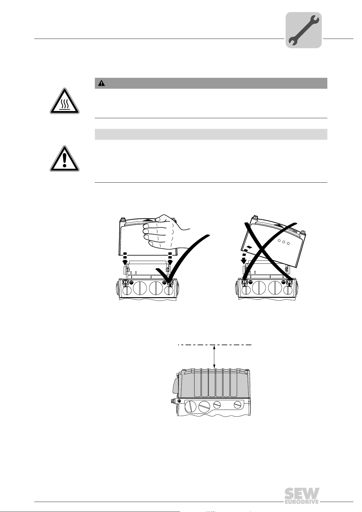
4.4.2 Electronics cover
NET RUN DRIVE
MOVIGEAR
®
B
SNI
NET RUN DRIVE
MOVIGEAR
®
B
SNI
Burns caused by hot surfaces.
Severe injuries.
• Let the units cool down before touching them.
NOTICE
Loss of the guaranteed degree of protection.
Possible damage to property.
• When the DRC electronics cover is removed from the connection box, you have to
protect it from humidity, dust or foreign particles.
• Check to see that the DRC electronics cover was mounted properly.
WARNING
Mechanical Installation
Setting up the drive unit
4
Installing the
electronics cover
Min. installation
clearance
• Use only electronics covers that match the size.
• Be careful not to tilt the electronics cover when placing it on the connection box.
4813126155
Note the minimum installation clearance (see following figure) required to remove the
DRC electronics cover. For detailed dimension drawings, see chapter "Technical data
and dimension sheets".
100
Operating Instructions – Electronic Motor DRC.-..-DAC
9007201604838411
25
4
4.4.3 Installation in damp locations or in the open
4.4.4 Painting drive units
Mechanical Installation
Setting up the drive unit
Drives are supplied in corrosion-resistant versions for use in damp areas or in the open.
Repair any damage to the paint work if necessary.
Observe the notes in chapter "Drive units with optional ASEPTIC / ASEPTIC
NOTICE
Breather valves and oil seals may be damaged during painting or re-painting.
Potential damage to property.
• Clean the surface of the drive unit and make sure it is free from grease.
• Thoroughly cover the breather valves and sealing lip of the oil seals with strips prior
to painting.
• Remove the strips after painting.
plus
design".
26
Operating Instructions – Electronic Motor DRC.-..-DAC
4.5 Tightening torques
WARNING
Burns caused by hot surfaces.
Severe injuries.
• Let the units cool down before touching them.
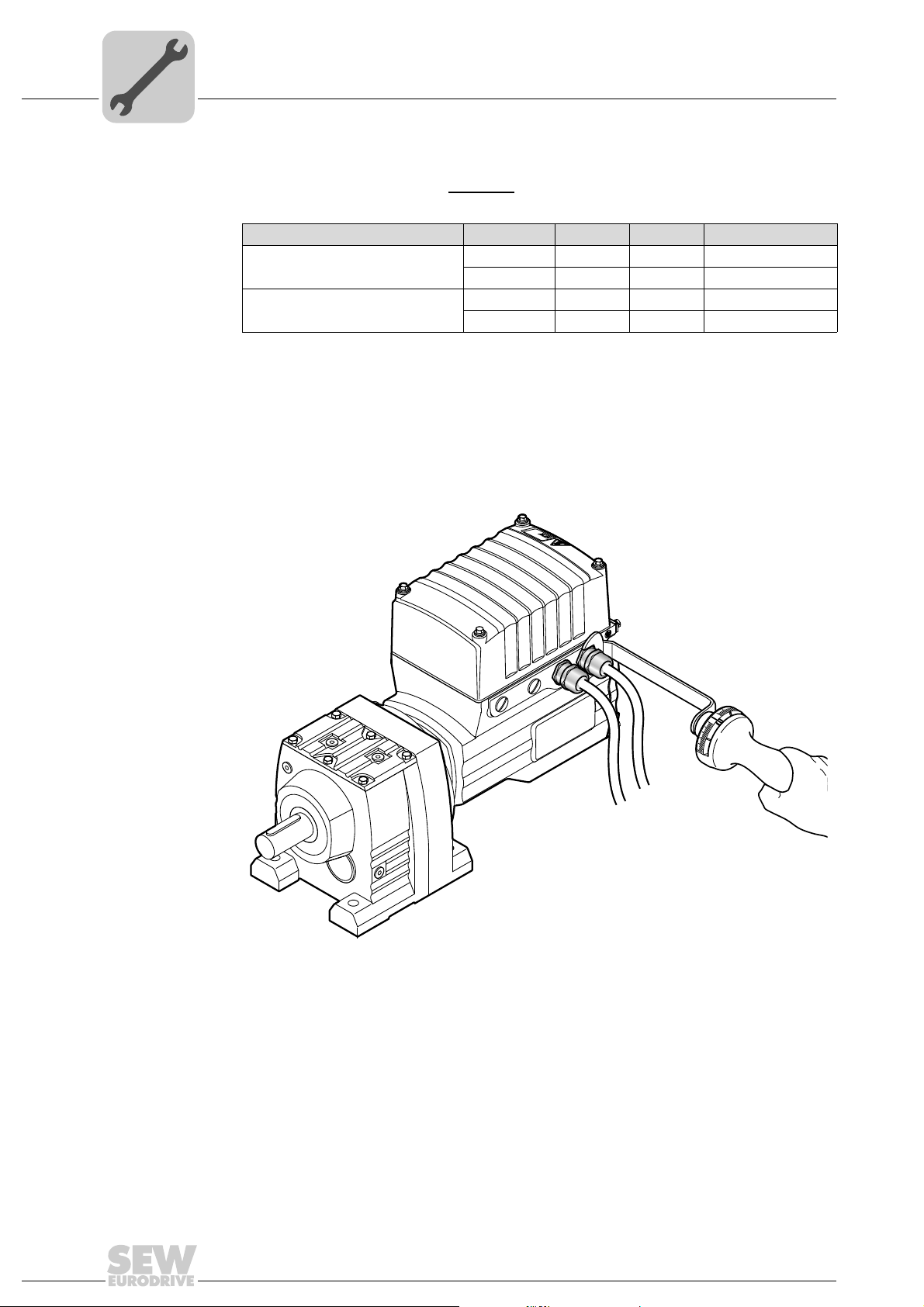
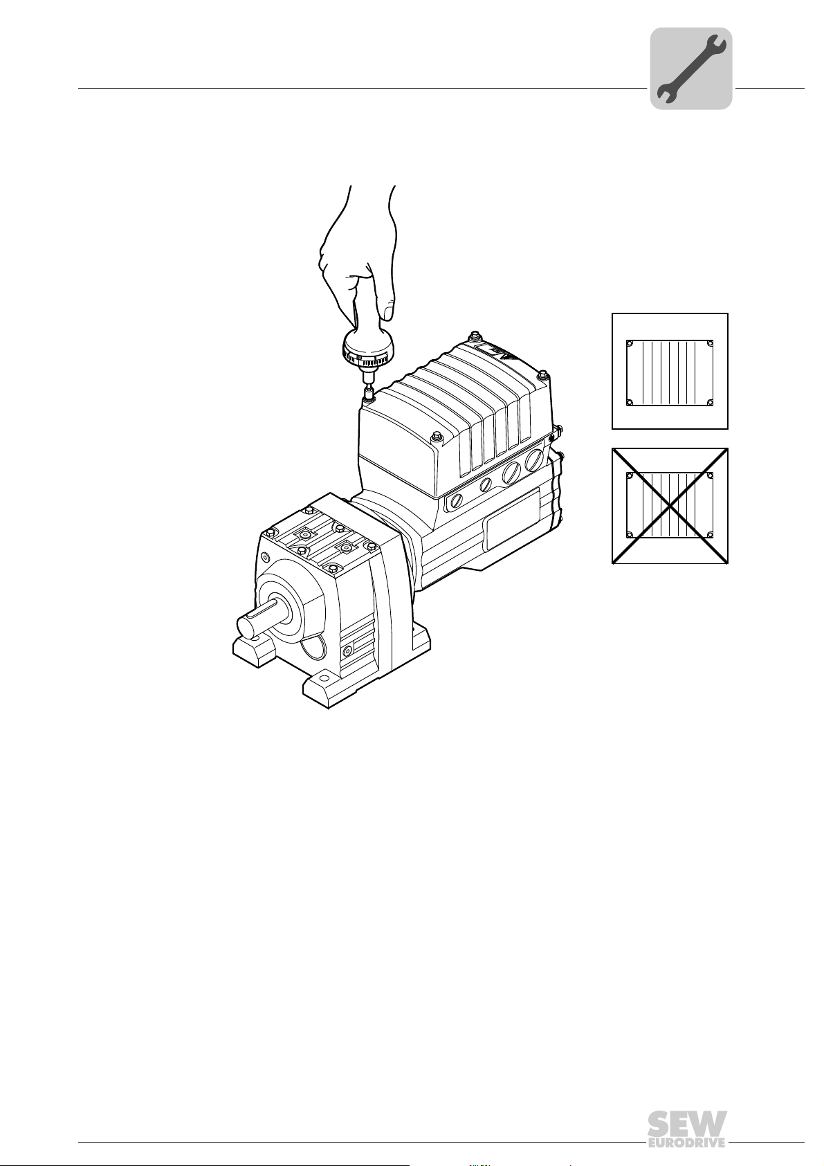
4.5.1 Blanking plugs
Mechanical Installation
Tightening torques
4
Tighten the blanking plugs included in the delivery
Example The following figure shows an example.
with 2.5 Nm:
Operating Instructions – Electronic Motor DRC.-..-DAC
9007203306591371
27
4
Mechanical Installation
Tightening torques
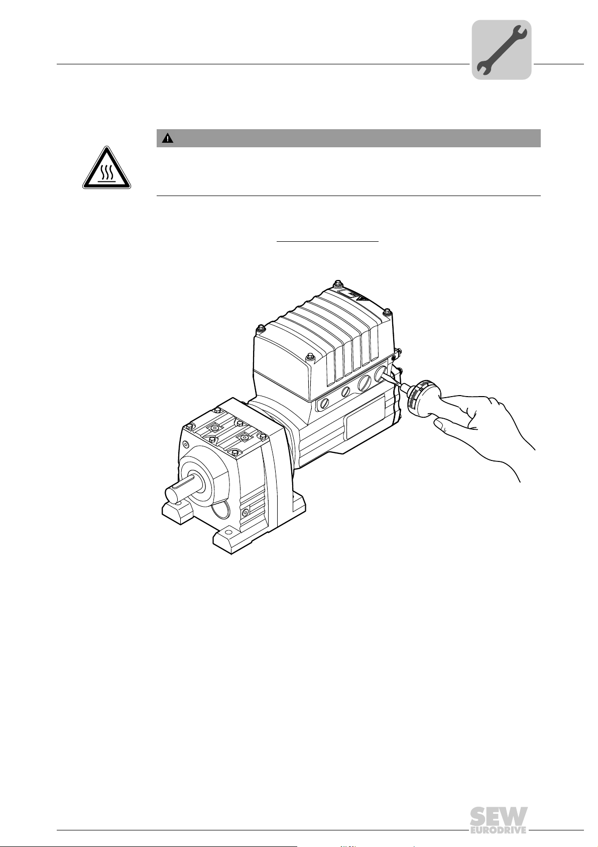
4.5.2 Cable glands
Tightening torques Tighten the EMC cable glands optionally
torques:
Screw fitting Part number Content Size Tightening torque
EMC cable glands (nickel-plated
brass)
EMC cable glands (stainless steel) 1821 636 6 10 pcs M16 x 1.5 3.5 Nm to 4.5 Nm
The cable retention in the cable gland must withstand the following removal force of the
cable from the cable gland:
• Cable with outer diameter from 4 to 8 mm: Min. 24 N
• Cable with outer diameter from 8 to 11 mm: Min. 34 N
• Cable with outer diameter from 11 to 16 mm: Min. 44 N
Example The following figure shows an example.
supplied by SEW-EURODRIVE to the following
1820 478 3 10 pcs M16 x 1.5 3.5 Nm to 4.5 Nm
1820 480 5 10 pcs M25 x 1.5 6.0 Nm to 7.5 Nm
1821 638 2 10 pcs M25 x 1.5 6.0 Nm to 7.5 Nm
28
9007203306596107
Operating Instructions – Electronic Motor DRC.-..-DAC
4.5.3 DRC electronics cover
1
2
4
3
4
2
3
1
Tighten the screws on the DRC cover using 6.0 Nm working diagonally across.
Mechanical Installation
Tightening torques
4
9007203306627211
Operating Instructions – Electronic Motor DRC.-..-DAC
29

4
Mechanical Installation
Drive units with optional ASEPTIC / ASEPTICplus design
4.6 Drive units with optional ASEPTIC / ASEPTIC
4.6.1 Installation notes
NOTICE
Loss of degree of protection IP66 and incompatibility with cleaning agents.
Possible damage to property.
• To achieve degree of protection IP66 and compatibility with cleaning agents, you
have to replace the plastic screw plugs delivered as standard by suitable screw
fittings made of stainless steel.
Adhere to the following additional notes for DRC drive units in optional ASEPTIC /
ASEPTIC
• Make sure to prevent moisture and dirt from entering the unit during installation.
• After electrical installation, make sure that the sealing and sealing surfaces are clean
• When performing maintenance work, check the condition of the gaskets as well as
• Make sure to install the cables with a drip loop.
• Use only stainless steel cable glands and connection glands offered by SEW-
plus
design:
during assembly.
the tightening torques of the screw fittings. If damaged: Consult SEW-EURODRIVE.
EURODRIVE, see chapter "Technical data and dimension sheets".
plus
design
• You must seal unused cable bushings and plug connectors with suitable screw
plugs, see chapter "Technical data and dimension sheets".
30
Operating Instructions – Electronic Motor DRC.-..-DAC
 Loading...