


Drive Technology \ Drive Automation \ System Integration \ Services
Operating Instructions
Electronic Motor
DRC.-...-SNI
Single Line Network Installation
Edition 02/2012 19376413 / EN

SEW-EURODRIVE—Driving the world

Contents
Contents
1 General Information ............................................................................................ 6
1.1 Use of this documentation .......................................................................... 6
1.2 Structure of the safety notes ....................................................................... 6
1.3 Rights to claim under limited warranty ........................................................ 7
1.4 Exclusion of liability..................................................................................... 7
1.5 Copyright..................................................................................................... 7
1.6 Product names and trademarks.................................................................. 7
2 Safety Notes ........................................................................................................ 8
2.1 General Information .................................................................................... 8
2.2 Target group ............................................................................................... 8
2.3 Designated use ........................................................................................... 9
2.4 Other applicable documentation ............................................................... 9
2.5 Transportation, storage ............................................................................. 9
2.6 Installation................................................................................................. 10
2.7 Electrical connection ................................................................................. 10
2.8 Safe disconnection.................................................................................... 10
2.9 Operation .............................................................................................. 11
3 Unit Structure .................................................................................................... 12
3.1 DRC drive unit ...................................................................................... 12
3.2 Cable entry positions .............................................................................. 13
3.3 Example nameplate and type designation of drive units ........................ 14
3.4 Electronics ............................................................................................ 15
3.5 Application options .............................................................................. 17
3.6 Example nameplate and type designation of electronics ...................... 19
3.7 DRC drive units in ASEPTIC / ASEPTIC
4 Mechanical Installation..................................................................................... 23
4.1 Installation notes ................................................................................... 23
4.2 Required tools and resources ................................................................... 23
4.3 Installation requirements........................................................................... 24
4.4 Setting up the drive unit ............................................................................ 25
4.5 Application options .............................................................................. 28
4.6 Tightening torques ............................................................................... 30
4.7 Drive units with optional ASEPTIC / ASEPTIC
5 Electrical Installation ........................................................................................ 39
5.1 Installation planning considering EMC aspects .................................... 39
5.2 Installation instructions.............................................................................. 41
5.3 Installation topology (example) ............................................................. 47
5.4 Terminal assignment .............................................................................. 48
5.5 Connecting DRC drive units ................................................................... 50
5.6 Cable routing and shielding .................................................................... 51
5.7 EMC cable glands ................................................................................. 55
5.8 Prescribed power leads ....................................................................... 56
5.9 Plug connectors .................................................................................... 57
plus
design ............................. 21
plus
design ...................... 33
Operating Instructions – Electronic Motor DRC.-..-SNI
3

Contents
5.10 Assignment of optional plug connectors ............................................... 62
5.11 Application options .............................................................................. 71
6 Startup................................................................................................................ 73
6.1 Startup notes ......................................................................................... 73
6.2 Lifting applications .................................................................................. 74
6.3 Prerequisties for startup ........................................................................ 74
6.4 Description of DIP switches .................................................................. 75
6.5 Startup procedure ................................................................................ 77
6.6 Starting up the GIO13B application option .......................................... 79
7 Operation of MOVITOOLS
7.1 About MOVITOOLS
7.2 First steps ................................................................................................ 83
7.3 Connection mode...................................................................................... 85
7.4 Executing functions of the units ................................................................ 87
8 Parameters ..................................................................................................... 89
8.1 Overview of parameters of the command PCB ....................................... 89
8.2 Overview of parameters for application options ..................................... 91
8.3 Overview of power section parameters ................................................... 93
8.4 Description of command PCB parameters.............................................. 106
8.5 Description of application option parameters ........................................ 109
8.6 Description of power section parameters................................................ 113
®
MotionStudio .................................................. 82
®
MotionStudio .......................................................... 82
9 Operation ..................................................................................................... 140
9.1 Local mode (only in conjunction with optional plug connector) ............. 140
9.2 Releasing the brake without drive enable signal ................................. 141
10 Service ............................................................................................................. 143
10.1 Malfunctions of the mechanical DRC drive ........................................... 143
10.2 Evaluating error messages ................................................................. 144
10.3 Switch-off responses ............................................................................. 145
10.4 Reset of error messages .................................................................. 145
10.5 Description of status and operating displays ...................................... 146
10.6 Error table ........................................................................................... 149
10.7 Unit replacement ................................................................................. 152
10.8 SEW-EURODRIVE Service ................................................................... 153
10.9 Shutdown ............................................................................................ 154
10.10 Storage ................................................................................................... 154
10.11 Extended storage .................................................................................... 154
10.12 Disposal ............................................................................................... 155
11 Inspection and Maintenance .......................................................................... 156
11.1 Determining the operating hours ......................................................... 156
11.2 Inspection and maintenance intervals ................................................... 157
11.3 Inspection and maintenance work .......................................................... 158
4
Operating Instructions – Electronic Motor DRC.-..-SNI

Contents
12 Technical Data and Dimension Sheets ......................................................... 160
12.1 Technical data ..................................................................................... 160
12.2 Technical data of application options ................................................ 163
12.3 Braking resistors ................................................................................... 165
12.4 Technical data of the brake ................................................................... 177
12.5 ASEPTIC / ASEPTIC
12.6 Surface protection ................................................................................. 179
12.7 Screw fittings........................................................................................... 181
12.8 Connection cables .......................................................................... 182
12.9 Dimension drawings ........................................................................... 184
13 EC Declaration of Conformity ...................................................................... 188
14 Address List .................................................................................................... 189
Index................................................................................................................. 200
plus
variants ......................................................... 178
Operating Instructions – Electronic Motor DRC.-..-SNI
5
1
General Information
Use of this documentation
1 General Information
Electronic Motor DRC.-..-SNI
1.1 Use of this documentation
The documentation is an integral part of the product and contains important information
on operation and service. The documentation is written for all employees who assemble,
install, start up, and service this product.
The documentation must be accessible and legible. Make sure that persons responsible
for the system and its operation, as well as persons who work independently on the unit,
have read through the documentation carefully and understood it. If you are unclear
about any of the information in this documentation, or if you require further information,
contact SEW-EURODRIVE.
1.2 Structure of the safety notes
1.2.1 Meaning of the signal words
The following table shows the grading and meaning of the signal words for safety notes,
notes on potential risks of damage to property, and other notes.
Signal word Meaning Consequences if disregarded
DANGER Imminent danger Severe or fatal injuries
WARNING Possible dangerous situation Severe or fatal injuries
CAUTION Possible dangerous situation Minor injuries
NOTICE Possible damage to property Damage to the drive system or its
INFORMATION Useful information or tip:
Simplifies the handling of the
drive system.
environment
1.2.2 Structure of the section-related safety notes
Section-related safety notes do not apply to a specific action, but to several actions
pertaining to one subject. The used symbols indicate either a general or a specific
hazard.
This is the formal structure of a section-related safety note:
SIGNAL WORD
Type and source of danger.
Possible consequence(s) if disregarded.
• Measure(s) to prevent the danger.
1.2.3 Structure of the embedded safety notes
Embedded safety notes are directly integrated in the instructions just before the description of the dangerous action.
This is the formal structure of an embedded safety note:
• SIGNAL WORD Nature and source of hazard.
Possible consequence(s) if disregarded.
– Measure(s) to prevent the danger.
6
Operating Instructions – Electronic Motor DRC.-..-SNI

Rights to claim under limited warranty
1.3 Rights to claim under limited warranty
A requirement of fault-free operation and fulfillment of any rights to claim under limited
warranty is that you adhere to the information in the documentation. Read the documentation before you start working with the unit!
1.4 Exclusion of liability
You must comply with the information contained in this documentation to ensure safe
operation and to achieve the specified product characteristics and performance
features. SEW-EURODRIVE assumes no liability for injury to persons or damage to
equipment or property resulting from non-observance of these operating instructions. In
such cases, any liability for defects is excluded.
1.5 Copyright
© 2012 – SEW-EURODRIVE. All rights reserved.
Unauthorized duplication, modification, distribution or any other use of the whole or any
part of this documentation is strictly prohibited.
General Information
1
1.6 Product names and trademarks
All brands and product names in this documentation are trademarks or registered trademarks of their respective titleholders.
Operating Instructions – Electronic Motor DRC.-..-SNI
7

2
Safety Notes
General Information
2 Safety Notes
2.1 General Information
The following basic safety notes must be read carefully to prevent injury to persons and
damage to property. The operator must ensure that the basic safety notes are read and
adhered to. Ensure that persons responsible for the system and its operation, as well as
persons who work independently on the unit, have read through the operating
instructions carefully and understood them. If you are unclear about any of the information in this documentation, or if you require further information, please contact SEWEURODRIVE.
Never install damaged products or take them into operation. Submit a complaint to the
shipping company immediately in the event of damage.
During operation, DRC drive units can have live, bare and movable or rotating parts as
well as hot surfaces, depending on their degree of protection.
Removing covers without authorization, improper use as well as incorrect installation or
operation may result in severe injuries to persons or damage to property.
Refer to the documentation for additional information.
2.2 Target group
Only qualified electricians are authorized to install, start up or service the units or
correct unit faults (observing IEC 60364 or CENELEC HD 384 or DIN VDE 0100 and
IEC 60664 or DIN VDE 0110 as well as national accident prevention guidelines).
Qualified electricians in the context of these basic safety notes are all persons familiar
with installation, assembly, startup and operation of the product who possess the
necessary qualifications.
All persons involved in any other work, such as transportation, storage, operation and
disposal, must be trained appropriately.
8
Operating Instructions – Electronic Motor DRC.-..-SNI

2.3 Designated use
DRC drive units are components intended for installation in electrical systems or machines.
In case of installation in machines, taking the DRC drive units into operation (i.e. start of
designated operation) is prohibited until it is determined that the machine meets the requirements stipulated in EC Directive 2006/42/EC (Machinery Directive).
Startup (i.e. the start of designated use) is only permitted under observance of EMC
directive 2004/108/EC (EMC Directive).
DRC drive units comply with the regulations of the Low Voltage Directive 2006/95/EC.
The standards given in the declaration of conformity are applied to the DRC drive units.
You must observe the technical data and information on the connection requirements
as provided on the nameplate and in the documentation.
2.3.1 Safety functions
DRC drive units may not
and expressly permitted.
Safety Notes
Designated use
perform safety functions unless these functions are described
2
2.3.2 Lifting applications
DRC drive units are not designed for use as safety devices in lifting applications.
2.4 Other applicable documentation
Note also the following documentation:
• "DRC Gearmotors" catalog
• Operating instructions for the gear unit (only for DRC gearmotors)
You can download or order these publications on the Internet (http://www.sew-
eurodrive.com under the heading "Documentation").
2.5 Transportation, storage
You must observe the notes on transportation, storage and proper handling. Comply
with the requirements for climatic conditions stated in chapter "Technical Data". Tighten
installed eyebolts securely. They are designed for the weight of the DRC drive unit. Do
not attach any additional loads. Use suitable, sufficiently rated handling equipment (e.g.
rope guides) if required.
Operating Instructions – Electronic Motor DRC.-..-SNI
9

2
Safety Notes
Installation
2.6 Installation
2.7 Electrical connection
The units must be installed and cooled according to the regulations and specifications
in the corresponding documentation.
Protect the DRC drive units from improper strain.
The following applications are prohibited unless explicitly permitted:
• Use in potentially explosive atmospheres.
• Use in areas exposed to harmful oils, acids, gases, vapors, dust, radiation, etc.
• Use in non-stationary applications that are subject to mechanical vibration and shock
loads as stated in the documentation for DRC drive units.
Important: DRC drive units and corresponding mount-on parts must not protrude into
footways.
Working on live parts of DRC drive units is not permitted.
The drive is operated as a generator due to the kinetic energy of the system/machine.
Secure the output shaft against rotation before opening the wiring compartment.
Electrical installation must be carried out in compliance with pertinent regulations (e.g.
cable cross sections, fusing, protective conductor connection). For any additional information, refer to the applicable documentation.
You find notes on EMC-compliant installation, such as shielding, grounding, arrangement of filters and routing of lines, in the documentation of the DRC drive units. The
manufacturer of the system or machine is responsible for maintaining the limits established by EMC legislation.
Protective measures and protection devices must comply with the regulations in force
(e.g. EN 60204-1 or EN 61800-5-1).
2.8 Safe disconnection
DRC drive units meet all requirements for safe disconnection of power and electronics
connections in accordance with EN 61800-5-1. All connected circuits must also satisfy
the requirements for safe disconnection to ensure reliable isolation.
10
Operating Instructions – Electronic Motor DRC.-..-SNI

2.9 Operation
Safety Notes
Operation
Systems with integrated DRC drive units must be equipped with additional monitoring
and protection devices according to the applicable safety guidelines, such as the law
governing technical equipment, accident prevention regulations, etc. Additional protective measures may be necessary for applications with increased potential risk. Changes
to DRC drive units using the operating software are permitted.
Do not touch live components and power connections immediately after separation of
the DRC drive units from the supply voltage because some capacitors might still be
charged. Wait at least for 10 minutes after the supply voltage has been switched off.
The connection boxes must be closed and screwed on before the supply voltages are
connected to DRC drive units.
The unit may still be live and connected to the power supply even if the operation LEDs
and other display elements are no longer illuminated.
Mechanical blocking or internal safety functions of the unit can cause a motor standstill.
Eliminating the cause of the problem or performing a reset may result in the drive restarting automatically. If, for safety reasons, this is not permitted for the driven machine,
disconnect the unit from the supply system before correcting the error.
Caution: Danger of burns: The surface temperatures of DRC drive units can be more
than 60 °C during operation.
2
Operating Instructions – Electronic Motor DRC.-..-SNI
11
3
3 Unit Structure
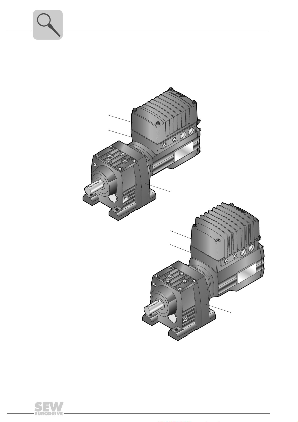
3.1 DRC drive unit
Unit Structure
DRC drive unit
The following figure depicts drive units consisting of DRC1/DRC2 electronic motor and
R gear unit:
R..DRC1-...
[1]
[2]
[3]
[1]
[2]
R..DRC2-...
[3]
12
9007203299592075
[1] Electronics cover
[2] DRC electronic motor with connection unit
[3] Gear unit (in the figure: R gear unit)
Operating Instructions – Electronic Motor DRC.-..-SNI
3.2 Cable entry positions
RUN
NET
DRIVE
3
X
2
The DRC electronic motor generally comes equipped with the following cable entries1):
• Position X + 2 + 3
– X: 2 x M25 x 1.5 + 2 x M16 x 1.5
– 2: 2 x M25 x 1.5 + 2 x M16 x 1.5
– 3: 2 x M25 x 1.5 + 2 x M16 x 1.5
Unit Structure
Cable entry positions
3
9007203301611787
1) 1 x M16 x 1.5 reserved for pressure compensation fitting (only in conjunction with ASEPTIC/ASEPTIC
variants as well as brakemotors operated at ambient temperatures of < 20 °C)
Operating Instructions – Electronic Motor DRC.-..-SNI
plus
13
3
[1]
[2]
76646 Bruchsal/Germany
kg AMB 1845 494 1.50°C
M
A
M
BR
Ma
pk
Nm
IM
Nm
Nm
i
kW
Iso.Kl. M.L. Hz 50-60 V A
nR
r/min IP
eff%
26.000
85...0.04
TENV
87,1 IE4
1.04
156
-20...40 Made in Germany
M1CLP 220 Miner.Öl/0.65 l
1/2000
23.59 62
155
0.55 S1
(F)
380...500
65
3~IEC61800
RF47 DRC1-005-SNI-A-ECR/IV
01.1751709009.0001.11
Inverter duty VPWM
Unit Structure
Example nameplate and type designation of drive units
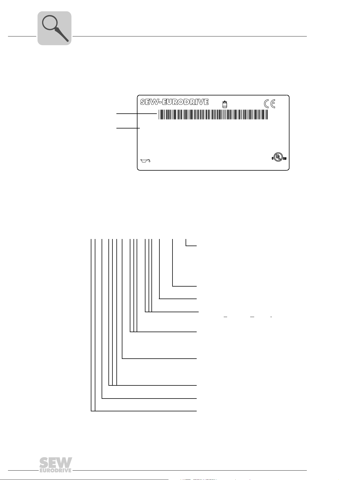
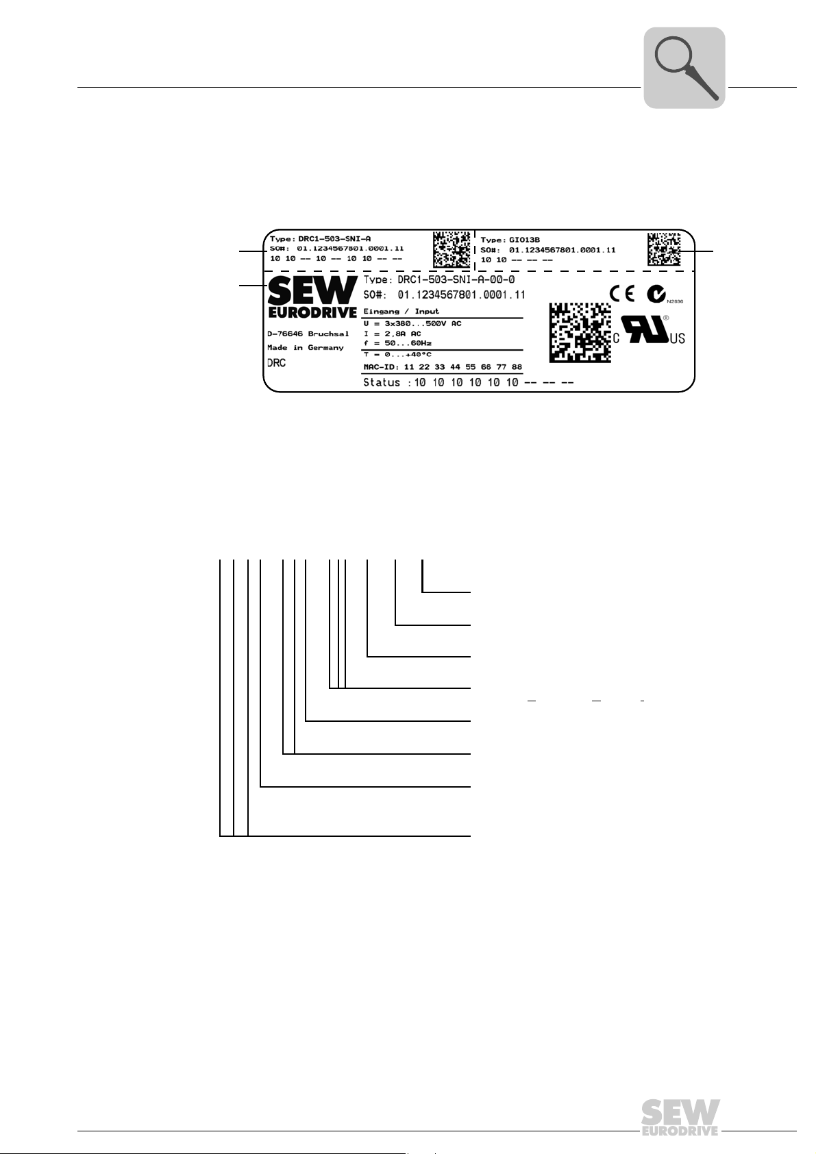
3.3 Example nameplate and type designation of drive units
3.3.1 Nameplate
The following figure gives an example of a DRC nameplate. For the structure of the type
designation, refer to chapter "Type designation".
[1] Unique serial number
[2] The bar code on the nameplate (code 39) according to ISO/IEC 16388 represents the unique
serial number (with a period as separator).
4762054411
3.3.2 Type designation
The following table shows the type designation of the DRC drive unit:
RF 47 DRC 1 - 005 - SNI - A - ECR / IV
DRC option
IV = Plug connector
BY1C = Brake DRC1
BY2C = Brake DRC2
BW1 = Integrated braking resistor DRC1
BW2 = Integrated braking resistor DRC2
Extended control range (standard)
Version
DRC installation technology
SNI = S
ingle Line Network Installation
Power rating
005 = 0.55 kW
015 = 1.5 kW
Electronic motor size
1 = DRC1
2 = DRC2
14
Product line
DRC = Electronic motor
Gear unit size
Gear unit series
Operating Instructions – Electronic Motor DRC.-..-SNI
3.4 Electronics
[2][1]
[7]
[6]
[7] [7][7]
[6]
[8]
[10][9]
[11]
[12]
[3] [4] [5]
[1]
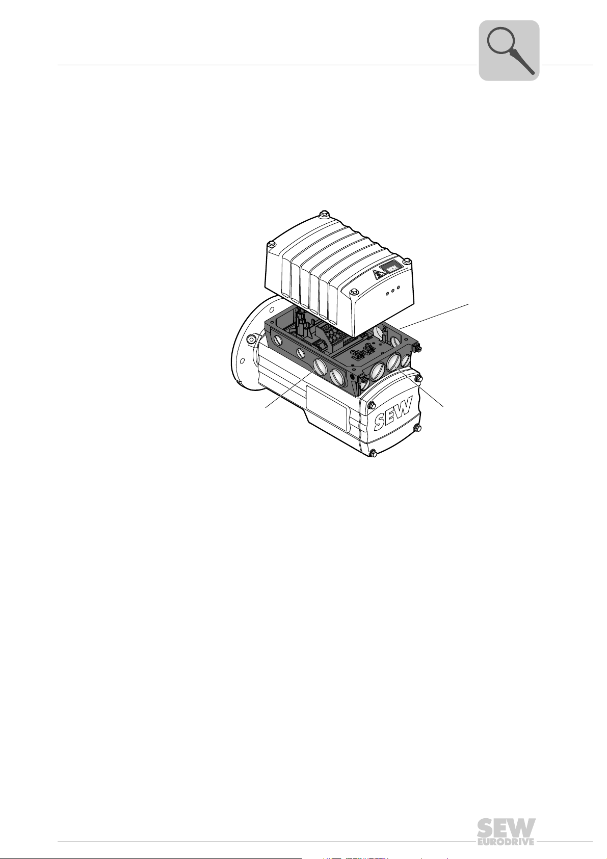
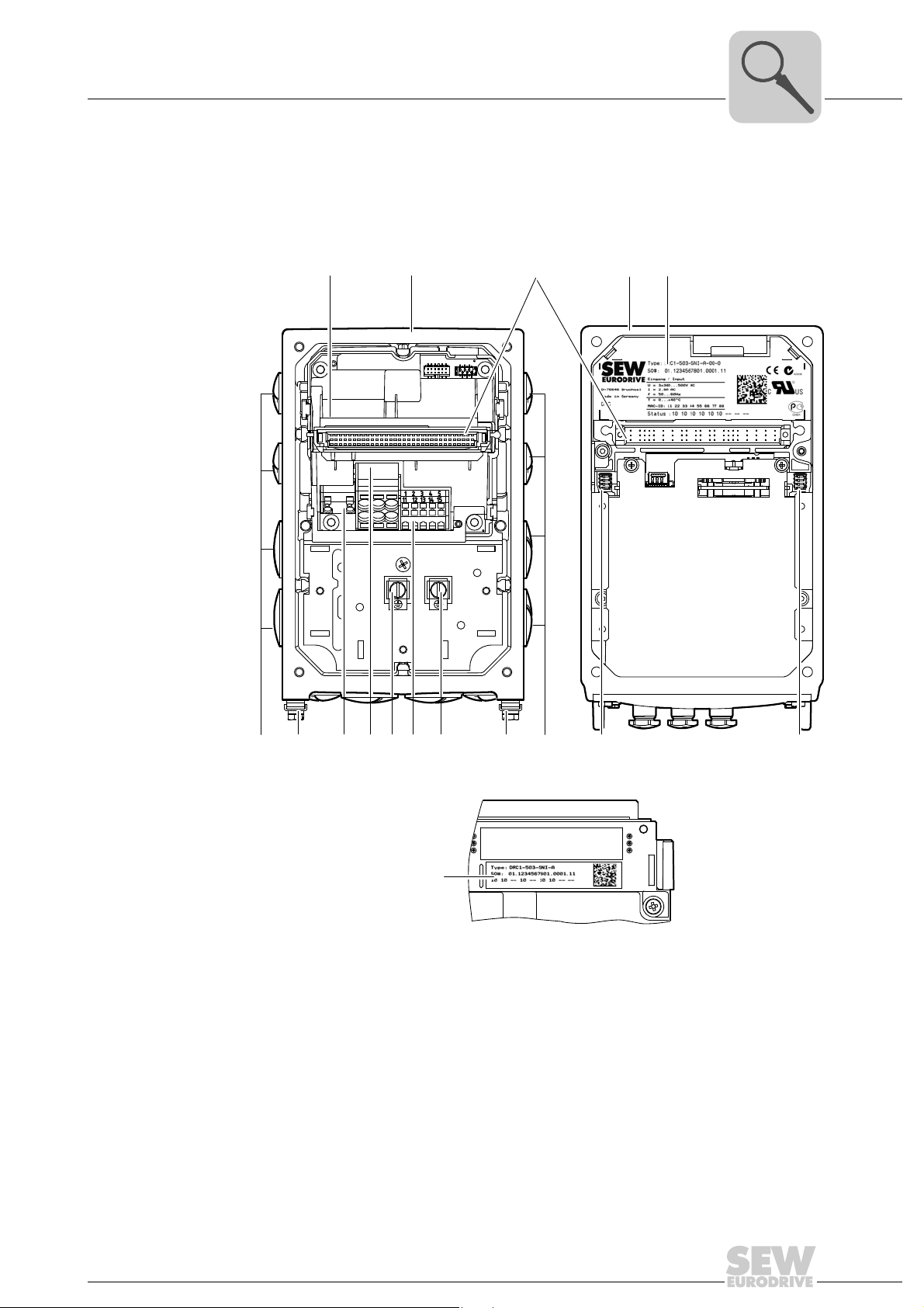
3.4.1 DRC electronics cover (inside) and connection box
The following figure shows the connection box and the bottom side of the DRC electronics cover:
Unit Structure
Electronics
3
4762915211
[1] Nameplate of drive unit, see following detailed view
[2] Connection box
[3] Plug connector connection unit for DRC electronics cover
[4] DRC electronics cover
[5] Electronics cover nameplate
[6] Cable glands
[7] Screws for PE connection
[8] Braking resistor connection
[9] Line connection L1, L2, L3
[10] Electronics terminal strips
[11] DIP switches S2/1 – S2/4
[12] DIP switches S1/1 – S1/4
4853331979
Operating Instructions – Electronic Motor DRC.-..-SNI
15
3
NET
RUN
DRIVE
NET
RUN
DRIVE
[1]
[1] [2] [3] [4]
AB
Unit Structure
Electronics
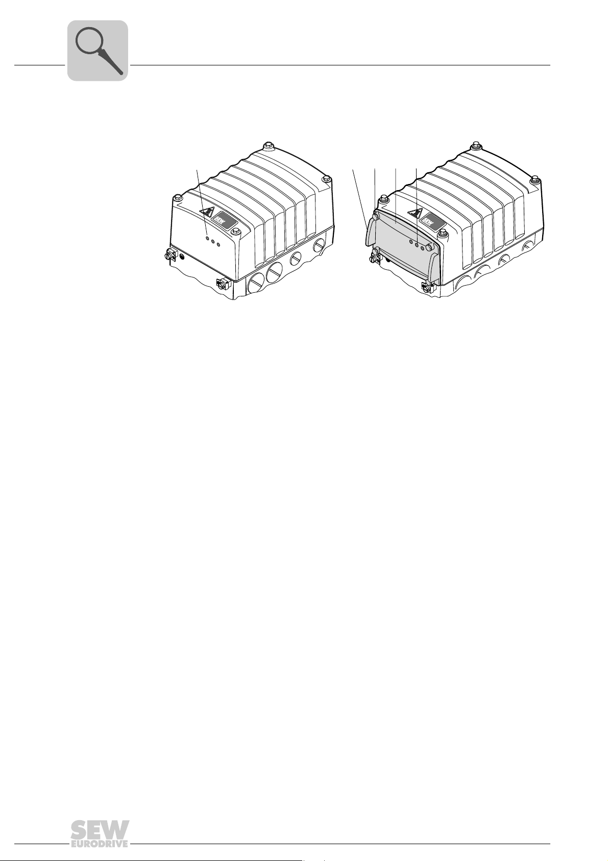
3.4.2 Electronics cover (outside)
The following figure shows possible types of the electronics cover:
A Electronics cover without application slot B Electronics cover with application slot
9007201622689931
[1] LED displays [1] Assembly/disassembly handle
[2] Retaining screws (4x)
[3] Application cover
[4] LED displays
16
Operating Instructions – Electronic Motor DRC.-..-SNI
3.5 Application options
[1] [2] [3]
NET
RUN
DRIVE
X4
X3
X2
X1
[1]
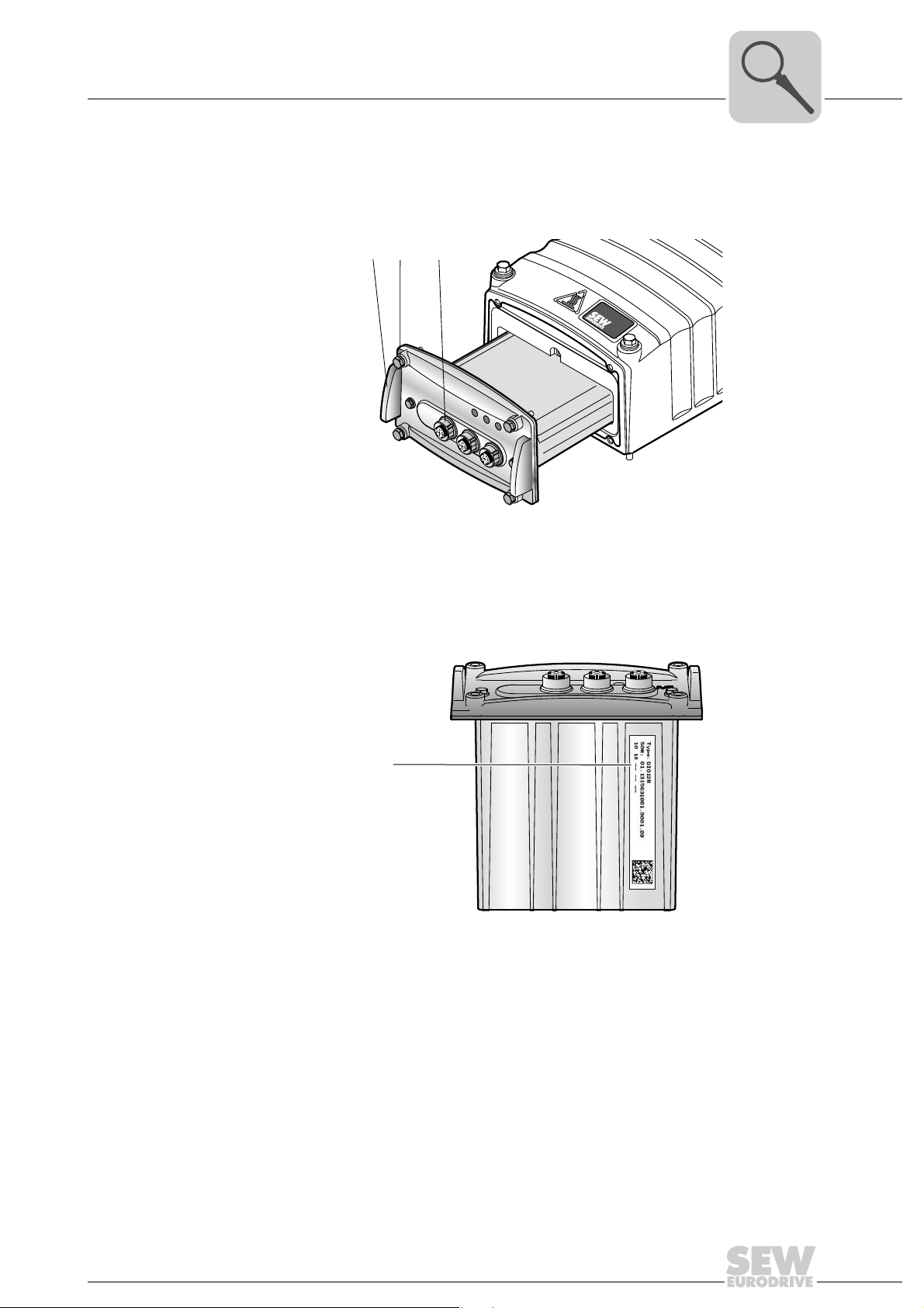
3.5.1 GIO12B application option
The following figure shows the GIO12B application option:
Unit Structure
Application options
3
[1] Assembly/disassembly handle
[2] Retaining screws (4x)
[3] M12 plug connector for digital I/Os
The following figure shows the position of the GIO12B nameplate:
[1] Nameplate
9007201622841227
18014401210968331
Operating Instructions – Electronic Motor DRC.-..-SNI
17
3
NET
RUN
DRIVE
ON
1234
ON
1234
ON
1234
ON
1234
ON
1234
S1
S2
S3
ON
1234
[1]
Unit Structure
Application options
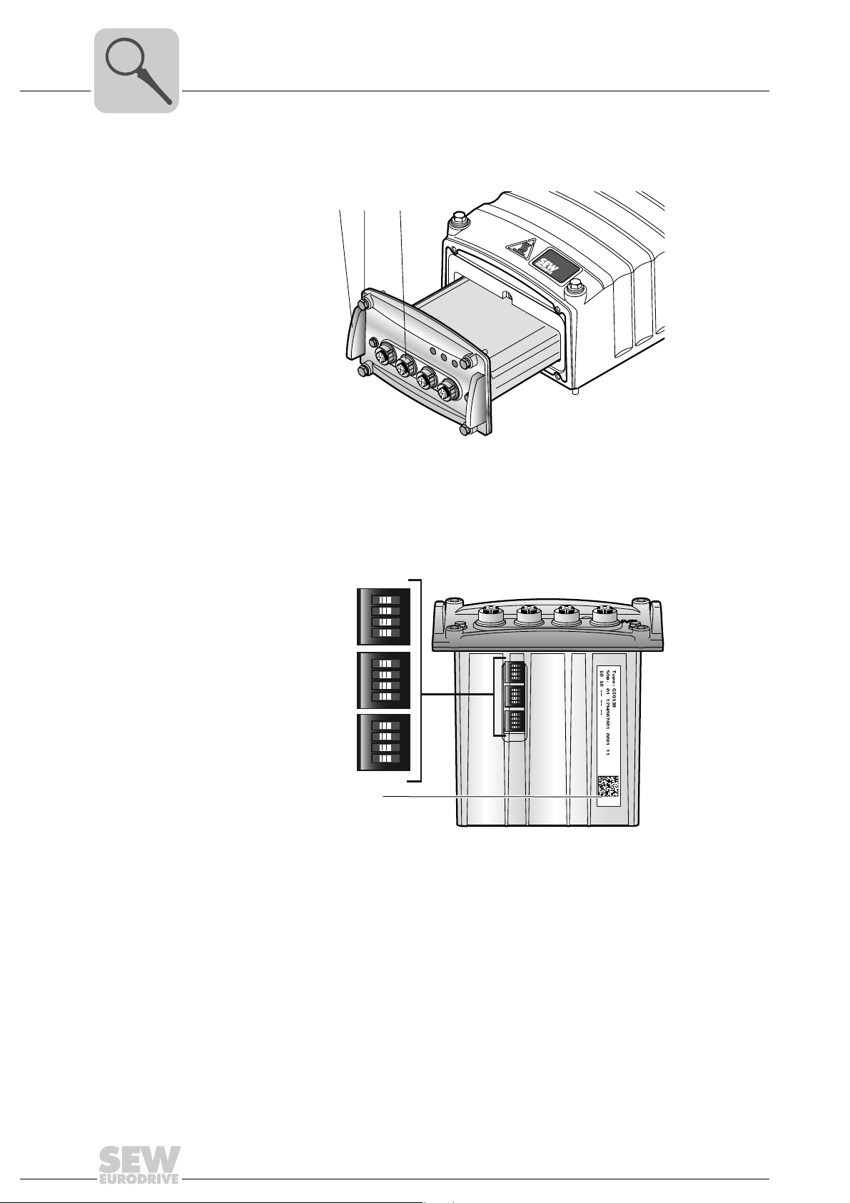
3.5.2 GIO13B application option
The following figure shows the GIO13B application option:
[1] [2] [3]
X4
X3
X2
X1
9007201839769867
[1] Assembly/disassembly handle
[2] Retaining screws (4x)
[3] M12 plug connector for digital/analog I/Os
The following figure shows the DIP switches S1 to S3 of the GIO13B application option:
18014401245670283
[1] Nameplate
18
Operating Instructions – Electronic Motor DRC.-..-SNI
Unit Structure
[1]
[3]
[2][1]
[3]
[2]
Example nameplate and type designation of electronics
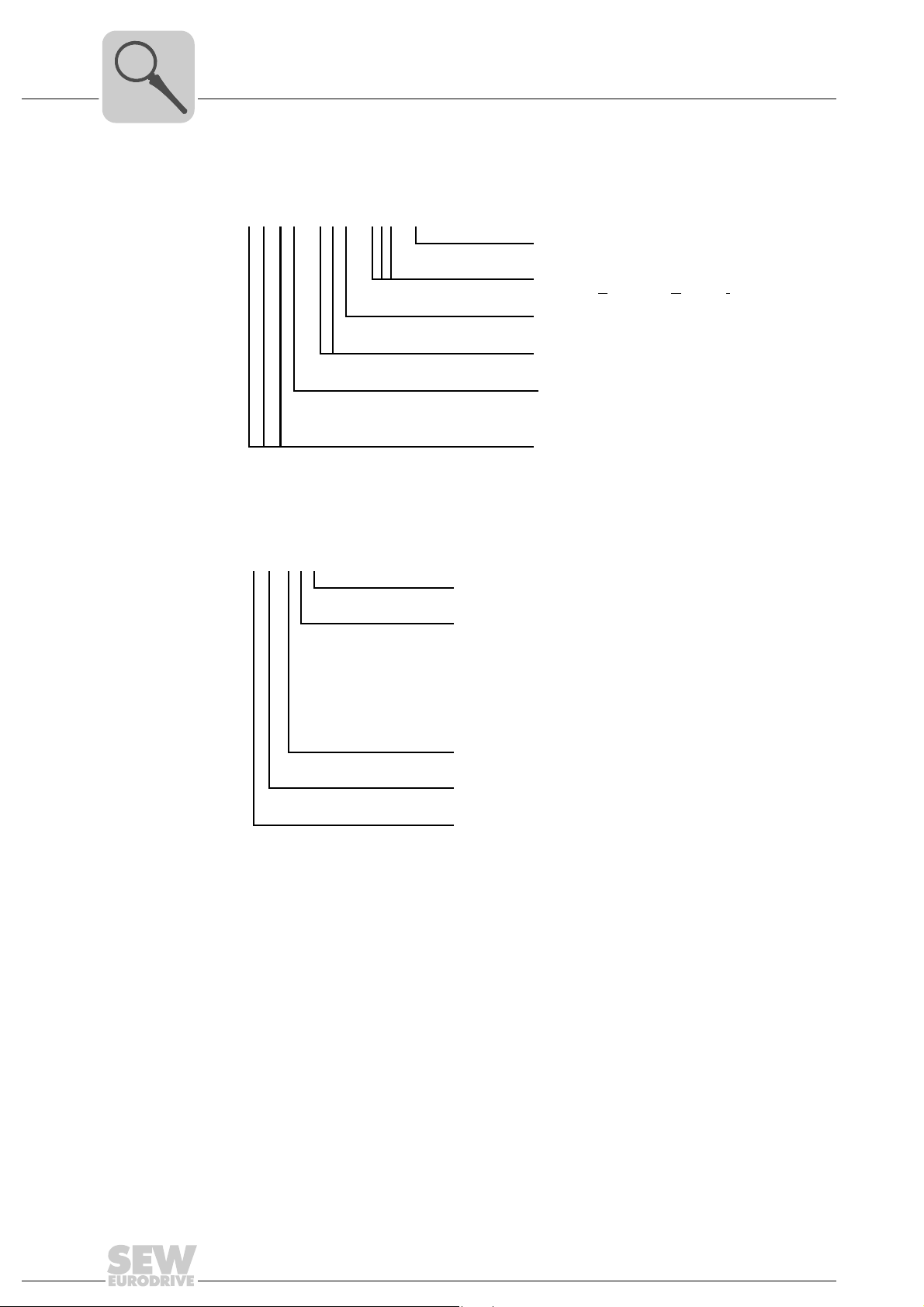
3.6 Example nameplate and type designation of electronics
3.6.1 Nameplate
The following figure gives an example of a DRC nameplate. For the structure of the type
designation, refer to chapter "Type designation".
[1] Nameplate of connection unit
[2] Nameplate of application option
[3] Nameplate of electronics cover
3
4766392075
3.6.2 Type designation electronics cover
The following table shows the type designation of the electronics cover:
D R C 1–5 0 3–SNI–A – 00 – A
Electronics cover variant
0 = Without application slot
A = With application slot
Variant
00 = Standard
DRC version
DRC installation technology
SNI = S
Connection type
3 = 3-phase (AC)
Supply voltage
50 = AC 380 – 500 V
Size
1
2
Product line
DRC = Electronic motor
ingle Line Network Installation
==DRC 1
DRC 2
Operating Instructions – Electronic Motor DRC.-..-SNI
19
3
Unit Structure
Example nameplate and type designation of electronics
3.6.3 Type designation of connection unit
The following table shows the type designation of the connection unit:
D R C 1–5 0 3–SNI–A
3.6.4 Type designation of application options
The following table shows the type designation for the available application options:
DRC version
DRC installation technology
SNI = Single Line Network Installation
Connection type
3 = 3-phase (AC)
Supply voltage
50 = AC 380 – 500 V
Size
1
==DRC 1
2
Product line
DRC = Electronic motor
DRC 2
G IO 1 2 B
Version
Variant
2 = 4 digital inputs + 2 digital outputs
3 = 4 digital inputs
(2 inputs can be used as primary frequency input)
+ 1 digital output
+ 1 analog input
+ 1 analog output
Version
Functionality
IO = Digital inputs/outputs
Product line
G = Option for MOVIGEAR
®
/ DRC
20
Operating Instructions – Electronic Motor DRC.-..-SNI
Unit Structure
MOVIGEAR
®
B
SNI
A
B
[B 2]
[B 1]
Y
X
X
Y
[A3]
[A3]
[A2]
[A1]
[A7]
[A6]
[A5]
DRC drive units in ASEPTIC / ASEPTICplus design
3
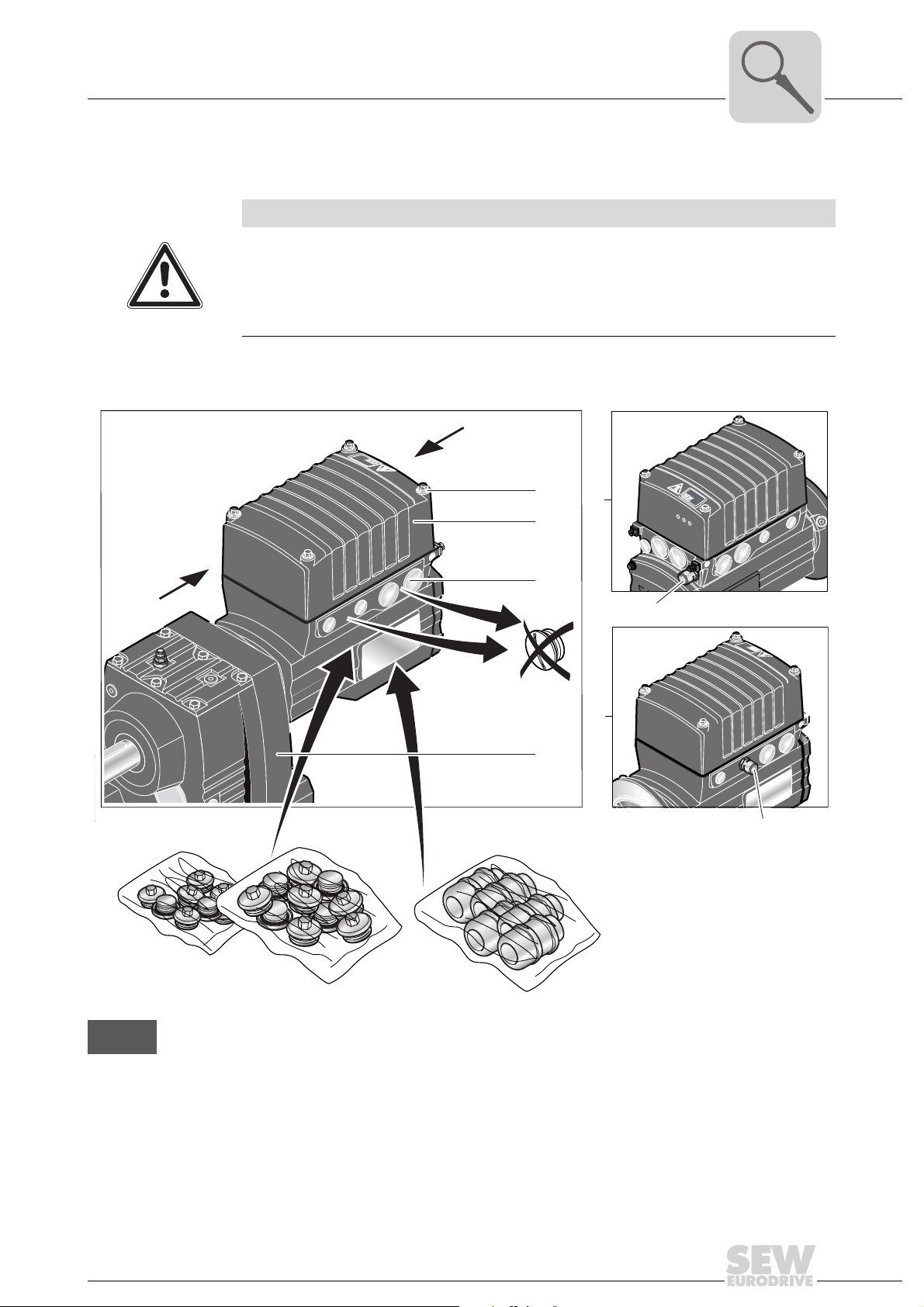
3.7 DRC drive units in ASEPTIC / ASEPTIC
NOTICE
Loss of degree of protection IP66 and incompatibility with cleaning agents.
Possible damage to property.
• To achieve degree of protection IP66 and compatibility with cleaning agents, you
have to replace the plastic screw plugs delivered as standard by suitable screw
fittings made of stainless steel.
The following picture shows the additional characteristics of DRC drive units in
ASEPTIC / ASEPTIC
plus
design:
plus
design
DRC
NET
RUN
DRIVE
All illustrations with ASEPTIC / ASEPTIC
tion) in this publication
plus
design are displayed with a shading (= HP200 surface protec-
4766218123
Operating Instructions – Electronic Motor DRC.-..-SNI
21

3
Unit Structure
DRC drive units in ASEPTIC / ASEPTICplus design
A Scope of delivery
[A1] Mounting screws for cover made of stainless steel
[A2] Surface protection OS2 to OS4 for ASEPTIC design / OS4 for ASEPTIC
plus
design, see chapter
"Technical data and dimension sheets"
[A3] The delivered plastic screw plugs must be replaced by suitable screw plugs made of stainless
steel.
[A5] Pre-installed pressure compensation fitting (M16) with mounting positions M5, M6
[A6] Pre-installed pressure compensation fitting (M16) with mounting position M1, M2, M4, M4
Optional plug connectors (see chapter "Electrical installation") are available in connection with the
ASEPTIC / ASEPTIC
plus
version.
[A7] Features of gear units in ASEPTIC design
– Surface protection finish OS2 to OS4
Features of gear units in ASEPTIC
plus
design
– Available for gear units with solid shaft, hollow shaft with key or TorqLOC for the following gear
unit sizes: R27-87, F27-87, K37-87 and W37
– Gear unit output shaft including all retaining parts on the output shaft, such as screws, keys,
shrink disk, etc., are made of stainless steel
– If technically possible, the oil seals on the output are configured as double oil seals made from
FKM (Viton
®
)
– The breather valve of the gear units is made from stainless steel
– Surface protection finish OS4 for compatibility with common cleaning agents and disinfectants
– All surface recesses sprayed with elastic rubber compound
– All gear unit options can be selected
– All mounting positions M1 to M6 are available
B Required screw fittings
[B1] Screw plugs made of stainless steel
[B2] Cable glands made of stainless steel
1)
1)
The required screw fittings can be ordered from SEW-EURODRIVE. For an overview, refer to chapter
"Technical Data / Optional metal screw fittings".
1) Make sure to select plug seals that are compatible with the cleaning agents used
22
Operating Instructions – Electronic Motor DRC.-..-SNI
4 Mechanical Installation
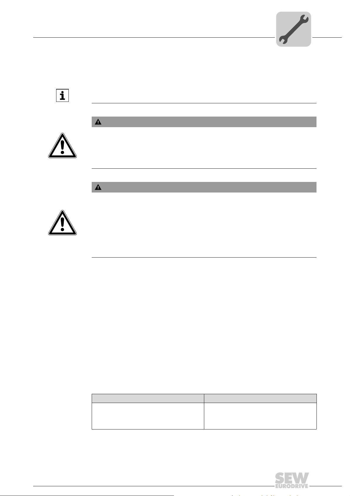
4.1 Installation notes
INFORMATION
Adhere to the safety notes during installation.
WARNING
Improper installation/disassembly of DRC drive units and mount-on components.
Risk of injury.
• Adhere to the notes about installation and disassembly.
• Before releasing shaft connections, make sure that there are no active torsional
moments present (tensions within the system).
WARNING
Risk of injury if the drive starts up unintentionally and danger of electrical voltage.
Mechanical Installation
Installation notes
4
Dangerous voltages may still be present for up to 10 minutes after disconnection from
the power supply.
Severe or fatal injuries.
• Disconnect the DRC drive unit from the power supply before you start working on
the unit and secure it against unintentional reconnection to the power supply.
• Secure the output shaft against rotation.
• Wait for at least 10 minutes before removing the electronics cover.
4.2 Required tools and resources
• Set of wrenches
• Torque wrench
• Mounting device
• Compensation elements (shims and spacing rings), if necessary
• Mounting materials for output components
• Lubricant (e.g. NOCO
• Standard parts are not included in the delivery
4.2.1 Installation tolerances for shaft ends
The following table shows the permitted tolerances of shaft ends and flanges of the
DRC motor.
®
Fluid)
Shaft end Flanges
Diameter tolerance according to EN 50347
• ISO j6 with Ø ≤ 26 mm
• Center bore in accordance with DIN 332,
shape DR..
Operating Instructions – Electronic Motor DRC.-..-SNI
Centering shoulder tolerance in accordance
with EN 50347
• ISO j6 with Ø ≤ 250 mm
23

4
Mechanical Installation
Installation requirements
4.3 Installation requirements
Check that the following conditions have been met:
• The entries on the nameplate of the DRC unit match the voltage supply system.
• The drive is undamaged (no damage caused by transportation or storage)
• Ambient temperature according to the operating instructions, nameplate and
lubricant table in chapter "Technical data and dimension sheets / Lubricants".
• The drive must not be assembled in the following ambient conditions:
– Potentially-explosive atmosphere
– Oils
–Acids
– Gases
– Vapors
– Radiation
• For special designs: The drive is designed in accordance with the actual ambient
conditions.
• You must clean the output shafts and flange surfaces thoroughly to ensure they are
free of anti-corrosion agents, contamination or similar. Use a commercially available
solvent. Do not expose the sealing lips of the oil seals to the solvent – damage to the
material.
• When the drive is installed in abrasive ambient conditions, protect the output end oil
seals against wear.
24
Operating Instructions – Electronic Motor DRC.-..-SNI

4.4 Setting up the drive unit
4.4.1 Notes
• Only install the DRC drive unit on a level, low-vibration, and torsionally rigid support
structure.
• Observe the mounting position specified on the motor nameplate.
• Thoroughly remove any anti-corrosion agent from the shaft end. Use a commercially
available solvent. Do not allow the solvent to penetrate the bearings and shaft seals
– this could damage the material.
• Align the motor carefully to avoid placing any unacceptable strain on the motor
shafts. Observe the permitted overhung and axial loads specified in the "DRC Gearmotors" catalog.
• Do not jolt or hammer the shaft end.
• Ensure that cooling air supply is unobstructed and that air discharged by other units
does not influence cooling.
• Balance components that were subsequently mounted to the shaft with a half key
(output shafts are balanced with a half key).
• Use suitable cable glands for the supply leads (use reducing adapters if necessary).
• Seal the cable entry properly.
Mechanical Installation
Setting up the drive unit
4
• Thoroughly clean the sealing surfaces of the DRC cover before re-assembly.
• If the corrosion protection coating is damaged, restore the coating.
• Check whether the degree of protection specified in the operating instructions and
on the nameplate is permitted in the ambient conditions on site.
Operating Instructions – Electronic Motor DRC.-..-SNI
25
4
NET RUN DRIVE
MOVIGEAR
®
B
SNI
NET RUN DRIVE
MOVIGEAR
®
B
SNI
4.4.2 Electronics cover
Mechanical Installation
Setting up the drive unit
WARNING
Burns caused by hot surfaces.
Severe injuries.
• Let the units cool down before touching them.
NOTICE
Loss of the guaranteed degree of protection.
Possible damage to property.
• When the DRC electronics cover is removed from the connection box, you have to
protect it from humidity, dust or foreign particles.
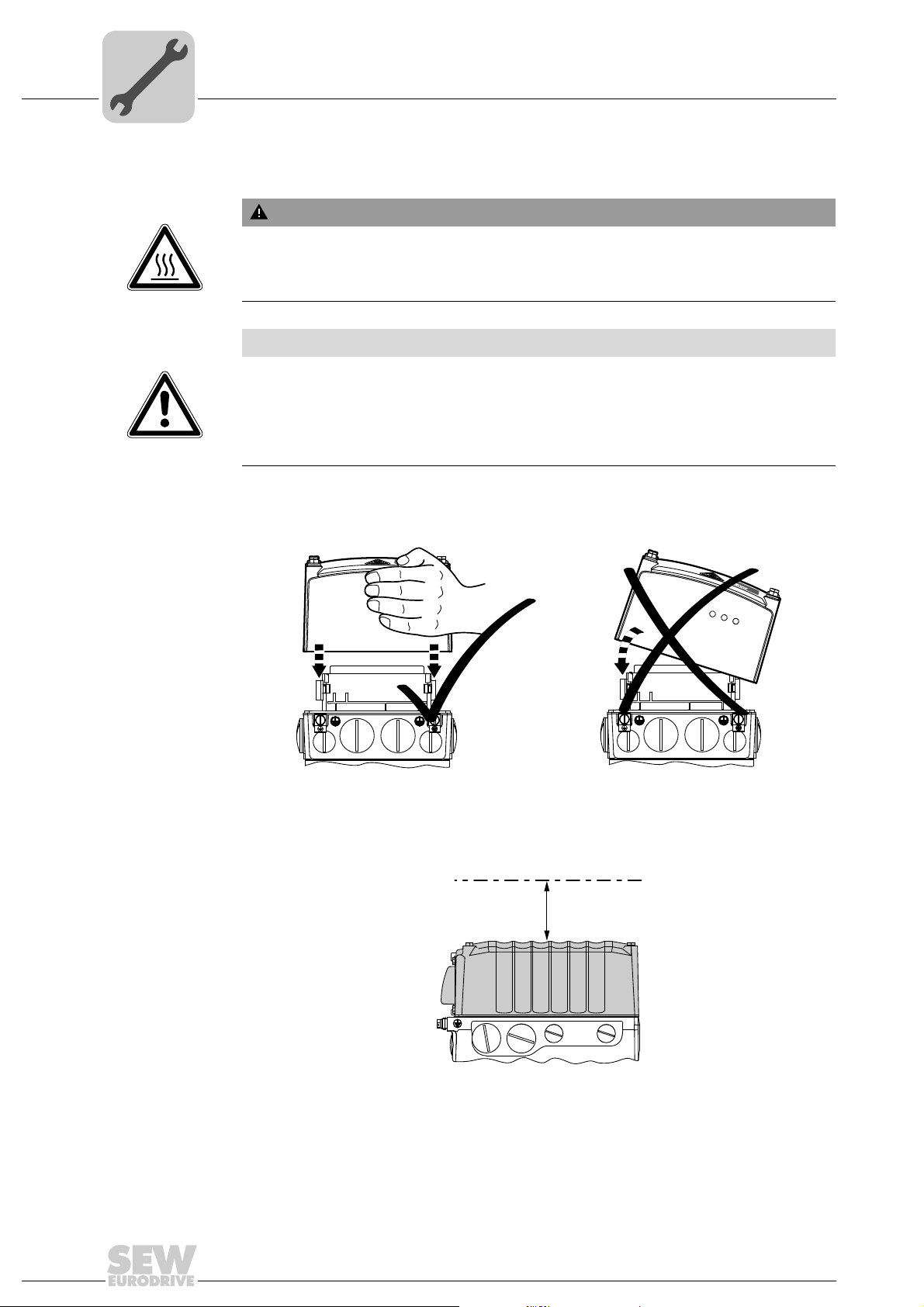
• Check to see that the DRC electronics cover was mounted properly.
Installing the
electronics cover
Min. installation
clearance
• Use only electronics covers that match the size.
• Be careful not to tilt the electronics cover when placing it on the connection box.
4813126155
Note the minimum installation clearance (see following figure) required to remove the
DRC electronics cover. For detailed dimension drawings, see chapter "Technical data
and dimension sheets".
100
26
9007201604838411
Operating Instructions – Electronic Motor DRC.-..-SNI
Mechanical Installation
Setting up the drive unit
4
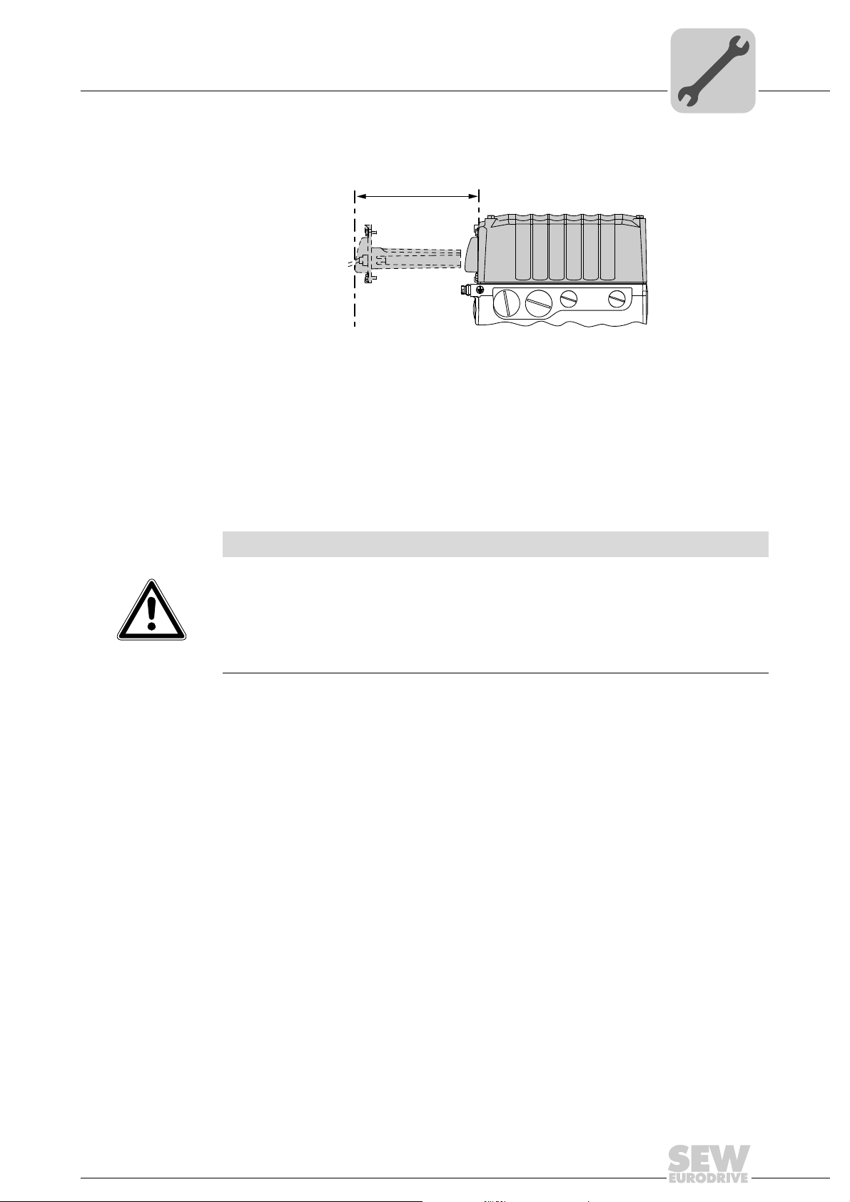
Min. installation
clearance of
application options
4.4.3 Installation in damp locations or in the open
4.4.4 Painting drive units
Note the minimum installation clearance (see following figure) required to install and
remove the application options.
200
Drives are supplied in corrosion-resistant versions for use in damp areas or in the open.
Repair any damage to the paint work if necessary.
Observe the notes in chapter "Drive units with optional ASEPTIC / ASEPTIC
NOTICE
Breather valves and oil seals may be damaged during painting or re-painting.
9007201604871563
plus
design".
Potential damage to property.
• Clean the surface of the drive unit and make sure it is free from grease.
• Thoroughly cover the breather valves and sealing lip of the oil seals with strips prior
to painting.
• Remove the strips after painting.
Operating Instructions – Electronic Motor DRC.-..-SNI
27

4
4 x
NET
RUN
DRIVE
Mechanical Installation
Application options
4.5 Application options
WARNING
Burns caused by hot surfaces.
Severe injuries.
• Let the units cool down before touching them.
4.5.1 Removing the application cover
DRC drive units with application slot in the electronics cover are delivered with an application cover as standard.
You have to remove the application cover in order to install an application option:
1. Loosen the 4 retaining screws.
2. Remove the application cover.
18014400859806987
NET
RUN
DRIVE
18014400859827339
28
Operating Instructions – Electronic Motor DRC.-..-SNI
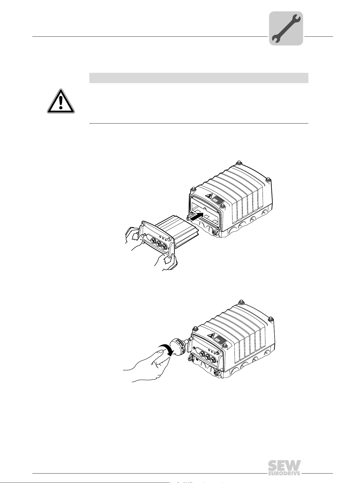
4.5.2 Installing the application options
NET
RUN
DRIVE
X4
X3
X2
X1
NOTICE
Loss of the guaranteed degree of protection.
Possible damage to property.
• In disassembled condition, you have to protect the GIO13 application option from
moisture, dust or foreign particles as there are openings for DIP switches.
• Make sure that the application cover is mounted properly.
1. You have to remove the application cover or, depending on the design, the paint
protector in order to install an application option:
2. Insert the option into the application slot.
Mechanical Installation
Application options
4
18014400859846539
3. Secure the option with the 4 retaining screws. The permitted tightening torque for the
retaining screws is 1.4 - 1.6 Nm.
4 x
NET
RUN
X4
DRIVE
X3
X2
X1
18014400859865739
Operating Instructions – Electronic Motor DRC.-..-SNI
29
4
Mechanical Installation
Tightening torques
4.6 Tightening torques
4.6.1 Blanking plugs
WARNING
Burns caused by hot surfaces.
Severe injuries.
• Let the units cool down before touching them.
Tighten the blanking plugs included in the delivery
Example The following figure shows an example.
with 2.5 Nm:
30
9007203306591371
Operating Instructions – Electronic Motor DRC.-..-SNI

4.6.2 Cable glands
Tightening torques Tighten the EMC cable glands optionally
torques:
Screw fitting Part number Content Size Tightening torque
EMC cable glands (nickel-plated
brass)
EMC cable glands (stainless steel) 1821 636 6 10 pcs M16 x 1.5 3.5 Nm to 4.5 Nm
1820 478 3 10 pcs M16 x 1.5 3.5 Nm to 4.5 Nm
1820 480 5 10 pcs M25 x 1.5 6.0 Nm to 7.5 Nm
1821 638 2 10 pcs M25 x 1.5 6.0 Nm to 7.5 Nm
The cable retention in the cable gland must withstand the following removal force of the
cable from the cable gland:
• Cable with outer diameter from 4 to 8 mm: Min. 24 N
• Cable with outer diameter from 8 to 11 mm: Min. 34 N
• Cable with outer diameter from 11 to 16 mm: Min. 44 N
Example The following figure shows an example.
Mechanical Installation
Tightening torques
supplied by SEW-EURODRIVE to the following
4
Operating Instructions – Electronic Motor DRC.-..-SNI
9007203306596107
31

4
1
2
4
3
4
2
3
1
Mechanical Installation
Tightening torques
4.6.3 DRC electronics cover
Tighten the screws on the DRC cover using 6.0 Nm working diagonally across.
9007203306627211
32
Operating Instructions – Electronic Motor DRC.-..-SNI

Mechanical Installation
Drive units with optional ASEPTIC / ASEPTICplus design
4
4.7 Drive units with optional ASEPTIC / ASEPTIC
4.7.1 Installation notes
NOTICE
Loss of degree of protection IP66 and incompatibility with cleaning agents.
Possible damage to property.
• To achieve degree of protection IP66 and compatibility with cleaning agents, you
have to replace the plastic screw plugs delivered as standard by suitable screw
fittings made of stainless steel.
Adhere to the following additional notes for DRC drive units in optional ASEPTIC /
ASEPTIC
• Make sure to prevent moisture and dirt from entering the unit during installation.
• After electrical installation, make sure that the sealing and sealing surfaces are clean
• When performing maintenance work, check the condition of the gaskets as well as
• Make sure to install the cables with a drip loop.
• Use only stainless steel cable glands and connection glands offered by SEW-
plus
design:
during assembly.
the tightening torques of the screw fittings. If damaged: Consult SEW-EURODRIVE.
EURODRIVE, see chapter "Technical data and dimension sheets".
plus
design
• You must seal unused cable bushings and plug connectors with suitable screw
plugs, see chapter "Technical data and dimension sheets".
Operating Instructions – Electronic Motor DRC.-..-SNI
33

4
MOVIGEAR
®
B
SNI
[1]
[3]
[2]
Mechanical Installation
Drive units with optional ASEPTIC / ASEPTICplus design
Example The following figure gives an example of a cable entry with drip loop and the replace-
ment of the plastic screw plugs supplied as standard with suitable stainless steel screw
fittings.
4768361227
[1] The delivered plastic screw plugs must be replaced by suitable screw plugs made of stainless steel.
[2] Required stainless steel screw plugs
(see chapter "Technical data and dimension sheets")
[3] Required stainless steel cable glands
(see chapter "Technical data and dimension sheets")
34
Operating Instructions – Electronic Motor DRC.-..-SNI

Mechanical Installation
3
2
NET
RUN
DRIVE
M3
x
3
2
MOVIGEAR
®
B
SNI
NET
RUN
DRIVE
MOVIGEAR
®
B
SNI
M1
M2
M4
M5
M6
2
3
2
3
2
x
2
3
x
3
x
x
x
Drive units with optional ASEPTIC / ASEPTICplus design
4
Mounting positions DRC drive units in optional ASEPTIC / ASEPTIC
plus
design are delivered with pressure
compensation and breather valve installed according to the mounting position.
plus
This is why DRC drive units in optional ASEPTIC / ASEPTIC
design must only be
used in the mounting position specified in the order.
• Mounting position
–M1
–M2
–M3
–M4
–M5
–M6
• Cable entries
– Position 3 (not permitted for M4 mounting position)
– Position 2 (not permitted for M5 mounting position)
– Position X (not permitted for M6 mounting position)
Mounting positions The following figure shows the position of the DRC drive unit when installed in mounting
positions M1 to M6:
4768583819
Operating Instructions – Electronic Motor DRC.-..-SNI
35

4
Mechanical Installation
Drive units with optional ASEPTIC / ASEPTICplus design
4.7.2 Tightening torques when using optional ASEPTIC
plus
design
WARNING
Burns caused by hot surfaces.
Severe injuries.
• Let the units cool down before touching them.
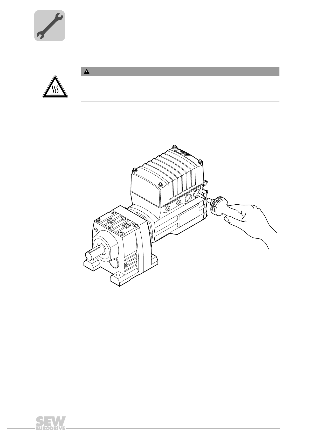
Blanking plugs Tighten the blanking plugs optionally
with 2.5 Nm:
Type of screw fitting Content Size Part number
Screw plugs
hexagon
(made of stainless steel)
Example The following figure shows an example. The number and position of cable entries
depends on the variant you have ordered.
included in the delivery by SEW-EURODRIVE
10 pcs M16 x 1.5 1 824 734 2
10 pcs M25 x 1.5 1 824 735 0
B
®
SNI
MOVIGEAR
36
4768590091
Operating Instructions – Electronic Motor DRC.-..-SNI

Mechanical Installation
Drive units with optional ASEPTIC / ASEPTICplus design
4
DRC electronics
cover
Proceed as follows when installing the DRC electronics cover:
B
®
SNI
MOVIGEAR
3
2
4
3
1
4
1
2
4768799755
Steps 1. Fix the DRC cover in position on the connection box with a tightening torque of 2 Nm
2. Tighten screws diagonally with 4 Nm.
3. Tighten screws with 6 Nm.
Operating Instructions – Electronic Motor DRC.-..-SNI
37

4
MOVIGEAR
®
B
SNI
Mechanical Installation
Drive units with optional ASEPTIC / ASEPTICplus design
EMC cable glands Tighten the EMC cable glands optionally included in the delivery by SEW-EURODRIVE
with the following tightening torques:
Screw fitting Part number Content Size Tightening torque
EMC cable glands (nickel-plated
brass)
EMC cable glands (stainless steel) 1821 636 6 10 pcs M16 x 1.5 3.5 Nm to 4.5 Nm
1820 478 3 10 pcs M16 x 1.5 3.5 Nm to 4.5 Nm
1820 480 5 10 pcs M25 x 1.5 6.0 Nm to 7.5 Nm
1821 638 2 10 pcs M25 x 1.5 6.0 Nm to 7.5 Nm
The cable retention in the cable gland must withstand the following removal force of the
cable from the cable gland:
• Cable with outer diameter > 10 mm: ≥ 160 N
• Cable with outer diameter < 10 mm: = 100 N
Example The following figure shows an example. The number and position of cable entries
depends on the variant you have ordered.
38
4769055499
Operating Instructions – Electronic Motor DRC.-..-SNI

Electrical Installation
Installation planning considering EMC aspects
5 Electrical Installation
INFORMATION
Adhere to the safety notes during installation.
5.1 Installation planning considering EMC aspects
5.1.1 Notes on arranging and routing installation components
Successful installation of decentralized drives depends on selecting the correct cables,
providing correct grounding and a functioning equipotential bonding.
Always apply the relevant standards.
Note the following:
5.1.2 EMC-compliant installation
5
INFORMATION
This drive system is not designed for operation on a public low voltage supply system
that supplies residential areas.
This is a product with restricted availability in accordance with IEC 61800-3. This
product may cause EMC interference. In this case, it is recommended for the operator
to take suitable measures.
For detailed information on EMC compliant installation, refer to the publication
"Electromagnetic Compatibility in Drive Engineering" from SEW-EURODRIVE.
With respect to the EMC regulation, frequency inverters cannot be operated as standalone units. Regarding EMC, they can only be evaluated when they are integrated in a
drive system. Conformity is declared for a described, CE-typical drive system. These
operating instructions contain further information.
5.1.3 Cable selection, routing and shielding
WARNING
Electric shock caused by faulty installation.
Severe or fatal injuries.
• Take the utmost care when installing the units.
• Observe the connection examples.
For more information on cable selection, routing and shielding, refer to chapter "Cable
routing and shielding".
Operating Instructions – Electronic Motor DRC.-..-SNI
39

5
NET
RUN
DRIVE
[1]
[3] [2]
[4]
Electrical Installation
Installation planning considering EMC aspects
5.1.4 Equipotential bonding
Example
Regardless of the protective earth connection, it is essential that low-impedance, HFcapable equipotential bonding is provided (see also EN 60204-1 or DIN VDE 0100-
540):
• Establish a connection over a wide surface area between the DRC drive unit and the
mounting rail.
• To do so, use a ground strap (HF litz wire), for example, to connect the DRC drive
unit and the plant's grounding point.
4867596683
[1] Conductive connection over a large area between drive unit and mounting plate
[2] PE conductor in the supply cable
[3] 2nd PE conductor via separate terminals
[4] EMC-compliant equipotential bonding, for example using a ground strap (HF litz wire)
• Do not use the cable shield of data lines for equipotential bonding.
40
Operating Instructions – Electronic Motor DRC.-..-SNI

5.2 Installation instructions
5.2.1 Connecting power supply cables
• The rated voltage and rated frequency of the DRC drive unit must correspond with
the data of the power supply system.
Electrical Installation
Installation instructions
5
• Cable cross section: According to input current I
at rated power (see chapter
line
"Technical data and dimension sheets").
• Install line fuses at the beginning of the power supply cable behind the supply bus
junction. Select the fuse size according to the cable cross section.
• Use only copper cables with a minimum temperature range of 85 °C as connection
cable.
• DRC drive units are intended to be operated on voltage supply systems with
grounded star point (TN and TT systems).
5.2.2 Permitted cable cross section of terminals
Line terminals Adhere to the permitted cable cross sections for installation:
Line terminals X2 without conductor end sleeve with conductor end sleeve (with
2
External braking
resistor terminals
Connection cross section
2
)
(mm
Connection cross section
(AWG)
Stripping length 13 mm – 15 mm
Current carrying capacity 24 A (max. continuous current)
0.5 mm
AWG20 – AWG10
Adhere to the permitted cable cross sections for installation:
External braking resistor
terminals X5
Connection cross section
2
)
(mm
Connection cross section
(AWG)
Stripping length 8 mm – 9 mm
without conductor end sleeve with conductor end sleeve
0.08 mm
2
– 4.0 mm
AWG28 – AWG12 AWG 23 – AWG 14
2
– 6 mm
or without insulating shroud)
2
(with or without insulating
shroud)
0.25 mm2 – 2.5 mm
2
Control terminals Adhere to the permitted cable cross sections for installation:
Control terminals X7 without conductor
Connection cross section
2
)
(mm
Connection cross section
(AWG)
Stripping length 5 mm – 6 mm
Current carrying capacity 3.5 A max. continuous current
Operating Instructions – Electronic Motor DRC.-..-SNI
end sleeve
0.08 mm
AWG 28 – AWG 14 AWG 23 – AWG 16
with conductor end
sleeve (without
insulating shroud)
2
– 2.5 mm
2
with conductor end
sleeve (with insulat-
ing shroud)
0.25 mm2 – 1.5 mm
2
41

5
1.
2.
2.
1.
5.2.3 Terminal activation for the braking resistor
5.2.4 Line terminal actuation
Electrical Installation
Installation instructions
Adhere to the following sequence when activating the terminals for the braking resistor:
Terminals for the braking resistor (the following figure shows a schematic illustration)
Adhere to the following sequence when actuating the line terminals:
4055861259
Line terminals (the following figure shows a schematic illustration)
5.2.5 Control terminal actuation
Adhere to the following sequence when actuating the control terminals:
Control terminals (the following figure shows a schematic illustration)
9007203310525451
2.
1.
42
3.
9007203462751499
Operating Instructions – Electronic Motor DRC.-..-SNI

Electrical Installation
Installation instructions
5.2.6 Line protection and residual current device (RCD or RCM)
WARNING
Electric shock due to incorrect earth-leakage circuit breaker type.
Severe or fatal injuries.
• The connected DRC drive units can cause direct current in the protective earth conductor. In cases where an earth-leakage circuit breaker is used for protection
against direct or indirect contact, only a type B earth-leakage circuit breaker is permitted on the power supply side of DRC drive units.
• Install the fuses at the beginning of the power supply cables behind the supply bus
junction.
• A conventional residual current device is not permitted. Residual current devices
sensitive to universal current (trip current 300 mA) are permitted. During normal
operation of DRC, earth-leakage currents of > 3.5 mA can occur.
• SEW-EURODRIVE recommends to not use residual current devices. However, if a
residual current device is stipulated for direct or indirect protection against contact,
observe the above note in accordance with EN 61800-5-1.
5
5.2.7 Line contactor
NOTICE
Damage to the DRC inverter due to jogging of the line contactor.
Damage to the DRC inverter.
• Do not use the line contactor (see wiring diagram) for jog mode but only for
• Observe a minimum switch-off time of 2 s for the line contactor.
• Use only a contactor of utilization category AC3 (EN 60947-4-1) as a line contactor.
switching the inverter on and off. For jog mode, use the control commands.
Operating Instructions – Electronic Motor DRC.-..-SNI
43

5
[1]
M5
2.5 mm²
M5
Electrical Installation
Installation instructions
5.2.8 Notes on PE connection
Electric shock due to incorrect connection of PE.
Severe or fatal injuries.
• The permitted tightening torque for the screw is 2.0 – 2.4 Nm (18 – 21 lb.in).
• Observe the following notes regarding PE connection.
WARNING
Prohibited assembly Recommendation:
Assembly with forked cable lug
Permitted for all cross sections
2377711243
[1] Forked cable lug suitable for M5 PE screws
2377688075
Assembly with solid connecting wire
Permitted for cross sections up to
max. 2.5 mm
2
2377672587
44
Earth-leakage currents ≥ 3.5 mA may occur during normal operation. To meet the
requirements of EN 61800-5-1, observe the following notes:
• The protective earth (PE) connection must meet the requirements for plants with high
earth-leakage currents.
• This usually means
– installing a PE connection cable with a minimum cross section of 10 mm
2
– or installing a second PE connection cable in parallel with the original PE connec-
tion.
Operating Instructions – Electronic Motor DRC.-..-SNI

5.2.9 Installation above 1000 m asl
Electrical Installation
Installation instructions
5
You can install DRC drive units at altitudes from 1000 m to a maximum of 4000 m above
sea level
• The nominal continuous power is reduced due to the reduced cooling above 1000 m
(see chapter "Technical data and dimension sheets").
• Above 2000 m above sea level, the air and creeping distances are only sufficient for
overvoltage class 2. If the installation requires overvoltage class 3, you will have to
install additional external overvoltage protection to limit overvoltage peaks to 2.5 kV
phase-to-phase and phase-to-ground.
• If safe electrical disconnection is required, it must be implemented outside the unit
for altitudes of 2000 m above sea level and higher (safe electrical disconnection in
accordance with EN 61800-5-1).
• At installation altitudes between 2000 m and 4000 m above sea level, the permitted
rated power supply voltages are reduced as follows:
– By 6 V per 100 m
5.2.10 Protection devices
• DRC drive units are equipped with integrated protection devices against overload.
• Cable protection must be implemented using external overload devices.
• Observe the relevant standards concerning cable cross section, voltage drop and
installation type.
1)
provided the following conditions are met:
INFORMATION
It is essential that you adhere to the installation instructions in the documentation of
the controller you use.
1) The maximum altitude is limited by the reduced electric strength due to the lower air density.
Operating Instructions – Electronic Motor DRC.-..-SNI
45

5
5.2.11 UL-compliant installation (in preparation)
Power terminals Observe the following notes for UL-compliant installation:
Electrical Installation
Installation instructions
• Use only copper cables with a rated thermal value of 75 °C.
• DRC uses cage clamp terminals
Short circuit
current rating
Branch circuit
protection
Motor overload
protection
Ambient
temperature
Wiring diagrams For wiring diagrams, refer to chapter "Electrical installation".
Suitable for use in current circuits with a maximum short circuit current of 200 000 A
• DRC, the max. voltage is limited to 500 V.
Integral solid state short circuit protection does not provide branch circuit protection.
Branch circuit protection must be provided in accordance with the National Electrical
Code and any additional local codes.
The table below list the permitted maximum fusing.
Series Max. fuse rating
DRC 40 A / 600 V
DRC is provided with motor overload protection with a trip current adjusted to 150% of
the rated motor current.
DRC is suitable for an ambient temperature of 40 °C, max. 60 °C with derated output
current. To determine the output current rating at temperatures above 40 °C, the output
current should be derated by 3.0% per K between 40 °C and 60 °C.
eff
:
46
Operating Instructions – Electronic Motor DRC.-..-SNI

5.3 Installation topology (example)
DRC...SNI
Single Line Installation [2]
[1]
DRC...SNI
MOVIGEAR
®
...SNI
Communication
Power
Power
Controller - SNI
Controller / PLC
Control cabinet level
Field level
Line filter
INFORMATION
The following figure shows the basic installation topology with DRC-SNI.
It is essential that you observe the installation instructions in the documentation of the
controller you use.
Electrical Installation
Installation topology (example)
5
[1]
A maximum of 10 SNI actuators in total
[2]
Operating Instructions – Electronic Motor DRC.-..-SNI
Permitted cable length between controller and last actuator max. 100 m
4727073035
47

5
PE
PE PE
PE
12 3
11 12 13
1
2
Braking resistor
terminals
Line terminals
X5
X2
12345
11 12 13 14 15
Control terminals
X7
12345
11 12 13 14 15
Electrical Installation
Terminal assignment
5.4 Terminal assignment
Electric shock due to regenerative operation when the shaft turns.
Severe or fatal injuries.
• Secure the output shaft against rotation when the electronics cover is removed.
The following figure shows the terminal assignment of DRC-SNI:
WARNING
4729233035
Assignment
Ter min al No. Name Marking Function (permitted tightening torque)
X2 line
terminals
1L1 Brown Actuator supply phase L1 with SNI communication – IN
2L2 Black Actuator supply phase L2 with SNI communication – IN
3L3 Gray Actuator supply phase L3 with SNI communication – IN
11 L 1 Brown Actuator supply phase L1 with SNI communication – OUT
12 L2 Black Actuator supply phase L2 with SNI communication – OUT
13 L3 Gray Actuator supply phase L3 with SNI communication – OUT
– PE – Protective earth connection (2.0 to 3.3 Nm )
X5 braking
resistor
terminals
1BW– Braking resistor connection
2BW– Braking resistor connection
INFORMATION
The communication method requires that you must observe the order of the line
phases L1, L2, L3 between SNI controller and DRC-SNI 1 to 10.
48
Operating Instructions – Electronic Motor DRC.-..-SNI

Electrical Installation
Terminal assignment
Assignment
Ter min al No. Name Marking Function
X7 control
terminals
1STO + Yellow Input STO +
2STO − Yellow Input STO –
3 +24 V_SEN – Input for DC 24 V voltage supply for sensors
The sensor supply voltage is then available at the
optional plug connector
4 0V24_SEN – Input for 0V24 reference potential for sensors
5 24V_O – DC 24 V output
11 STO + Yellow Output STO + (to loop through)
12 STO − Yellow Output STO – (to loop through)
13 +24V_SEN – Looping of the DC 24 V voltage supply for sensors
14 0V24_SEN – Looping of the 0V24 reference potential for sensors
15 0V24_O – 0V24 reference potential output
5
Operating Instructions – Electronic Motor DRC.-..-SNI
49

5
Electrical Installation
Connecting DRC drive units
5.5 Connecting DRC drive units
WARNING
No safe disconnection of the DRC drive unit.
Severe or fatal injuries.
• Do not use the 24 V output (terminals 5, 15) for safety-related applications with
DRC drive units.
• You may only jumper the STO input with 24 V when the DRC drive unit need not
fulfill any safety function.
[1] SNI controller connection
[7]
L1 IN1L2 IN
X2
Line terminals [2]
Control
terminals [2]
X7
2 STO IN
1 STO + IN
11 STO + OUT
L3 IN
L1 OUT11L2 OUT12
2
3
[3] [4] [5]
5 24V_O
12 STO OUT
L3 OUT
13
15 0V24_O
13 + 24V_SEN
3 + 24V_SEN
BW
BW
1
2
X5
Braking resistor
terminals [2]
[6] Connection the
for sensor inputs
4 0V 24V_SEN
14 0V 24V_SEN
DRC.-...-SNI
optional
plug connector
X5132
4729927435
50
[1] See documentation of the SNI controller
[2] See chapter "Terminal assignment"
[3] DC 24 V output
[4] Sensor supply input, the sensor supply voltage is then available at the optional plug
connector for sensor inputs
[5] Looping of the sensor supply input
[6] See chapter "Optional plug connector assignment"
[7] Braking resistor connection
Operating Instructions – Electronic Motor DRC.-..-SNI

5.6 Cable routing and shielding
A1:
A2:
B:
2x
2x
3x
3x
M4x10
(2.0 Nm)
M4x10
(2.0 Nm)
20mm
20mm
3x
2x
5.6.1 Installation material kit (part no. 1 824 826 8)
1)
Each DRC drive unit
material for cable shielding:
• A1: Installation material for line and hybrid cables:
2 x shield clamps and screws
(outer shield).
• A2: Conductive film:
2 x pieces of conductive film to wind around the braid shield. Use the conductive film
if required.
• B: Installation material for control cables and data cables:
3 x shield clamp with screw
(STO, CAN, binary signals).
is delivered with an accessory bag that contains installation
2)
Electrical Installation
Cable routing and shielding
2)
to connect the shield of line cables or hybrid cables
to connect the shield of control cables or data cables
5
INFORMATION
For some installation variants, you do not need all the parts of the accessory kit.
1) Exception: Not for plug connector variants
2) Self cutting, which is why the holes in the connection box do not have a thread
Operating Instructions – Electronic Motor DRC.-..-SNI
4071209995
51

5
5.6.2 General installation options
Electrical Installation
Cable routing and shielding
The following figure shows the general installation options. The following chapters show
common examples and contain important notes on cable selection and routing.
4071462539
52
Operating Instructions – Electronic Motor DRC.-..-SNI

5.6.3 Notes on cable routing and shielding
Note the following when routing and shielding the cables:
• Cable selection
– Only use cable types prescribed by SEW-EURODRIVE.
– It is essential that you observe chapter "Technical data and dimension sheets /
Specification of recommended connection cables for single line installation" in the
operating instructions.
– Always use metal cable glands due to their attenuation properties.
– Use shielded cables for the optional external braking resistor.
– The shield must have good EMC properties (high shield attenuation) and must not
be used for mechanical protection of the cable.
• Cable shielding – Control cables
– Connect the shields of the control cables to the metal housing of the unit using
the shield clamps of the installation material kit. To do so, strip off the cable
sheath around the shield connection surface.
– As an alternative, you can use optionally available EMC cable glands to connect
the shield of control cables, see chapter "EMC cable glands".
Electrical Installation
Cable routing and shielding
5
• Cable shield – external braking resistor
– Connect the cable shield of the cable for an external braking resistor to the metal
housing of the unit using the shield clamps of the installation material kit. To do
so, strip off the cable sheath around the shield connection surface.
• Cable shielding – Supply system cable (single line)
– Wind the conductive film included in the installation material kit around the braid
shield three times, if required.
– Connect the cable shields of the supply system cable (single line) to the metal
housing of the unit using the shield clamps of the installation material kit.
Operating Instructions – Electronic Motor DRC.-..-SNI
53

5
Single Line
(SNI)
STO
STO
External
braking
resistor
20mm
3x
Single Line (SNI)
STO
STO
External
braking resistor
20mm
3x
Recommended cable routing
Electrical Installation
Cable routing and shielding
Alternative cable routing
4731813899
54
Operating Instructions – Electronic Motor DRC.-..-SNI
4732273419

5.7 EMC cable glands
5.7.1 Cable shielding (alternative) – Control cables
As an alternative to using shield clamps for control cables (STO, binary signals), you can
use EMC cable glands, which are available as an option, to connect the shield.
Electrical Installation
EMC cable glands
5
3388566411
5.7.2 Assembly of EMC cable glands
Fit the EMC cable glands supplied by SEW-EURODRIVE according to the following
figure:
[1]
[1] Important: Cut off the insulating foil, do not just fold it back.
Operating Instructions – Electronic Motor DRC.-..-SNI
2661188747
55

5
Electrical Installation
Prescribed power leads
5.8 Prescribed power leads
The following table shows the available SNI supply system cables:
SNI supply system cable
Part no. 1 330 330 9 Cable reel 30 m
Cable reel 100 m
Cable reel 200 m
Open cable end
(bulk cable)
Part no. 1 330 550 6 Cable reel 30 m
Cable reel 100 m
Cable reel 200 m
Cable cross
section/cable type
2
2.5 mm
HELUKABEL
®
TOPFLEX
UV-2YSLCYK-J
TOPFLEX
UV-2YSLCYK-J
– EMV-
2
4 mm
HELUKABEL
®
– EMV-
Open cable end
(bulk cable)
56
Operating Instructions – Electronic Motor DRC.-..-SNI

5.9 Plug connectors
The wiring diagrams of the plug connectors depict the contact end of the connection.
5.9.1 Designation key
The designation of plug connectors is specified according to the following key:
X 2 0 1 2 _
Electrical Installation
Plug connectors
Sequence number (optional)
In case of several plug connectors in one group
Group number (optional)
For several plug connectors with the same function
Typ e
Connection diagram of the plug connector within a function
Function
Function of a plug connector within a group
Group
1 = Power input
2 = Power output
3 = Encoder
4 = Bus
5 = Inputs and outputs
5
5.9.2 Connection cables
Connection cables are not included in the scope of delivery.
You can order prefabricated cables from SEW-EURODRIVE. They are described in the
following sections. Specify the part number and length of the required cable in your
order.
The number and type of required connection cables depend on the design of the units
and the components to be connected. This is why not all cables in the list are actually
required.
The following figures show the various cable types:
Cable Length Installation type
Ter minal
Fixed length
Variable length
Suitable for cable
carrier installation
Not suitable for
cable carrier
installation
INFORMATION
For detailed information about cable types, see chapter "Technical data and
dimension sheets".
Operating Instructions – Electronic Motor DRC.-..-SNI
57

5
[1]
X5502
X1241_1
X1241_1 X1241_1
X1241_2
X1241_2
X1241_2
X5503
X5131X5131
X5131
[1]
X
2
3
Electrical Installation
Plug connectors
5.9.3 Plug connector positions
The following figure shows possible plug connector positions. A difference is made
between plug connectors with selectable position and plug connectors with fixed
position:
Plug connector Color Position Location
X5131: Digital inputs/outputs – As
X5502: STO – IN Orange Fixed 3 (left)
X5503: STO – OUT Orange Fixed 3 (right)
X1241_1: AC 400 V connection with SNI
1)
X1241_2: AC 400 V connection with SNI Red As
2)
[1] Pressure compensation
1) Plug connector X1241_1 is also available separately (i.e. without plug connector X1241_2).
2) Only in conjunction with the optional design for use in wet areas (with MOVIGEAR
(with DRC).
Red As
– Fixed Depends on mounting position
required
required
required
X, 2 or 3,
not together with X1241_1, X1241_2
X, 2 or 3, not together with X5131
X, 2 or 3, not together with X5131
®
) / ASEPTIC design
58
9007201923558283
Operating Instructions – Electronic Motor DRC.-..-SNI

Electrical Installation
[1]
5.9.4 Restrictions in conjunction with pressure compensation
The position for STO plug connectors is occupied by the pressure compensation fitting
[1] when using the optional design for use in wet areas (with
MOVIGEAR
case, plug connectors for STO are not possible:
®
)/ASEPTIC
plus
design (with DRC) and M5, M6 mounting position. In this
Plug connectors
5
9007201700846347
Operating Instructions – Electronic Motor DRC.-..-SNI
59

5
5.9.5 Plug connector variant
Electrical Installation
Plug connectors
NOTICE
Possible damage of the right-angle connector in case of rotation without mating
connector.
Irreparable damage to the thread, damage to the sealing surface.
• Do not use pliers to adjust the right-angle connector before connecting it.
NOTICE
Adjusting the right-angle connector too often can damage it.
Potential damage to property
• Adjust the plug connector only when installing and connecting the drive unit.
• Do not turn the plug connector regularly once it has been installed.
M23 plug connectors are available in the following variants:
• [1] "Straight" plug connector variant
• [2] "Right-angle" plug connector variant
Once the mating connector has been plugged in, the "right-angle" connector can be
adjusted without using additional tools.
60
Operating Instructions – Electronic Motor DRC.-..-SNI

Example
[2]
[1]
90 °
Electrical Installation
Plug connectors
5
9007203327550219
INFORMATION
Only cable outlet on the side is possible with plug connector position 3 and "rightangle" plug connector variant.
Operating Instructions – Electronic Motor DRC.-..-SNI
61

5
A
6
4
5
PE
B
C
D
SHLD
1
2
3
Electrical Installation
Assignment of optional plug connectors
5.10 Assignment of optional plug connectors
WARNING
Electric shock when disconnecting or connecting voltage-carrying plug connectors.
Severe or fatal injuries
• Switch off the power supply voltage.
• Never plug or unplug plug connectors while they are energized.
5.10.1 X1241_1 and X1241_2: AC 400 V connection with SNI
The following table informs about this connection:
Function
AC 400 V connection for supplying the unit/for looping through
with Single Line Network Installation (SNI)
Connection type
M23, SEW insert, SpeedTec-capable, company: Intercontec, female, coding ring: Red, protected against
contact
Wiring diagram
2497125387
Assignment
No. Name Function
A L1_SNI Actuator supply phase L1 with SNI communication
B L2_SNI Actuator supply phase L2 with SNI communication
C L3_SNI Actuator supply phase L3 with SNI communication
D n.c. Not connected
PE PE PE connection
1 n.c. Not connected
2 n.c. Not connected
3 n.c. Not connected
4 n.c. Not connected
5 n.c. Not connected
6 n.c. Not connected
7 n.c. Not connected
8 n.c. Not connected
9 n.c. Not connected
10 n.c. Not connected
SHLD n.c. Not connected
INFORMATION
The communication method requires that you must observe the order of the line
phases L1, L2, L3 between SNI controller and DRC SNI drive units 1 to 10.
62
Operating Instructions – Electronic Motor DRC.-..-SNI

Electrical Installation
Assignment of optional plug connectors
Connection cables The following table provides an overview of the cables available for this connection:
5
Connection cable
Part number 1 812 750 9
M23, coding ring:
Red
Part number 1 812 751 7
Open M23, coding ring:
Part number 1 812 752 5
M23, coding ring:
Red
Part number 1 812 753 3
M23, coding ring:
M23, coding ring:
Red
Red
Red
Length/
installa-
tion type
Variable
Variable
Variable
Cable cross-
section/
cable type
2
2.5 mm
HELUKA-
BEL
EMV-UV-
2.5 mm
HELUKA-
BEL
EMV-UV-
2
4 mm
HELUKA-
BEL
EMV-UV-
®
2
®
®
TOPFLEX
2YSLCYK-J
TOPFLEX
2YSLCYK-J
TOPFLEX
2YSLCYK-J
Operat-
ing
voltage
AC 500 V
–
AC 500 V
–
AC 500 V
–
Connection of
cables with open
end
2
4 mm
Variable
Open M23, coding ring:
Red
HELUKA-
BEL
TOPFLEX
EMV-UV-
2YSLCYK-J
®
–
AC 500 V
The following table shows the conductor assignment of the cable with the following part
number:
1 812 751 7 and 1 812 753 3
Signal name Color coding
L1_SNI Brown
L2_SNI Black
L3_SNI Gray
PE Green/yellow
Operating Instructions – Electronic Motor DRC.-..-SNI
63

5
9
1
2
7
6
5
11
12
3
4
8
10
Electrical Installation
Assignment of optional plug connectors
5.10.2 X5131: Digital inputs/outputs
The following table informs about this connection:
Function
Digital inputs/outputs for DRC MotionControl
Connection type
M23, P insert 12-pole, SpeedTec-capable, Intercontec, female, 0°-coded
Wiring diagram
2264820107
Assignment
No. Name Function
Motion control inputs
DIP switch S2/3 = OFF
1 DI01 DI01 sensor input CW/stop
2 DI02 DI02 sensor input CCW/stop
3 DI03 DI03 sensor input Setpoint f1/f2
4 DI04 DI04 sensor input Changeover
5 n.c. Not connected Not connected
6 n.c. Not connected Not connected
7 n.c. Not connected Not connected
8 +24V_O Reserved DC 24 V output
9 0V24V_O Reserved 0V24 reference potential
10 0V24V_SEN 0V24 reference potential for sensors
must be supplied via terminals
11 +24V_SEN DC 24 V sensor supply
Must be supplied via terminals X7.3
12 FE Equipotential bonding/functional ground Equipotential bonding/functional
1) see operating instructions, chapter "Connecting DRC drive units"
1)
Function
Local mode
DIP switch S2/3 = ON
Automatic/local mode
1)
Reserved
Reserved
ground
INFORMATION
Use actuator/sensor distributors with 4 slots for the sensor inputs. Use the DC 24 V
output only for local mode.
64
Operating Instructions – Electronic Motor DRC.-..-SNI

Electrical Installation
Assignment of optional plug connectors
Connection cables The following table provides an overview of the cables available for this connection:
5
Connection of
cables with open
end
Connection cable
Part number 1 174 145 7
Open M23, 12-pole,
Length/
Installation
type
Var iable
0°-coded
Operating
voltage
DC 60 V
The following table shows the conductor assignment of the cable with the following part
number:
1 174 145 7
Signal name Color coding
DI01 Pink
DI02 Gray
DI03 Red
DI04 Blue
Reserved Yellow
Reserved Green
Reserved Violet
+24V_O Black
0V24_O Brown
0V24_SEN White
+24V_SEN Gray/pink
FE Red/blue
Operating Instructions – Electronic Motor DRC.-..-SNI
65

5
5.10.3 X5502: STO – IN
Electrical Installation
Assignment of optional plug connectors
WARNING
No safe disconnection of the DRC drive unit.
Severe or fatal injuries.
• Do not use the 24 V output (pins 1 and 3) for safety-related applications with DRC
drive units.
• You may only jumper the STO input with 24 V when the DRC drive unit need not
fulfill any safety function.
The following table informs about this connection:
Function
Input for safe torque off (STO)
Connection type
M12, 5-pole, female, A-coded
Connection cables
Wiring diagram
1
4
Assignment
No. Name Function
1 +24V_O DC 24 V output
2STO − Input STO –
3 0V24_O 0V24 reference potential
4 STO + Input STO +
5 res. Reserved
2
3
5
2264816267
INFORMATION
Use only shielded cables for this connection and only suitable plug connectors that
connect the shield with the unit in an HF-capable manner.
66
Operating Instructions – Electronic Motor DRC.-..-SNI

Electrical Installation
Assignment of optional plug connectors
The following table provides an overview of the cables available for this connection:
5
Connection cable
Part number 1 812 496 8
M12, 5-pole, A-coded M12, 5-pole,
A-coded
Part number 1 812 497 6
Open M12, 5-pole,
A-coded
Part number 1 812 740 1
Length/
Installation
type
Variable
Variable
Operating
voltage
DC 60 V
DC 60 V
Connection of
cables with open
end
Variable
DC 60 V
M12, 5-pole, A-coded M12, 5-pole,
A-coded
Part number 1 812 739 8
Variable
DC 60 V
Open M12, 5-pole,
A-coded
The following table shows the conductor assignment of the cable with the following part
number:
1 812 497 6 and 1 812 739 8
Signal name Core color/designation
STO − Black / 1
STO + Black / 2
Operating Instructions – Electronic Motor DRC.-..-SNI
67

5
2
1
5
4
3
5.10.4 X5503: STO – OUT
Electrical Installation
Assignment of optional plug connectors
The following table informs about this connection:
Function
Connection for safe torque off (STO) for looping through
Connection type
M12, 5-pole, male, A-coded
Wiring diagram
2264818187
Assignment
No. Name Function
1 res. Reserved
2STO − Output STO – (to loop through)
3 res. Reserved
4 STO + Output STO + (to loop through)
5 res. Reserved
68
Operating Instructions – Electronic Motor DRC.-..-SNI

Connection cables
Electrical Installation
Assignment of optional plug connectors
INFORMATION
Use only shielded cables for this connection and only suitable plug connectors that
connect the shield with the unit in an HF-capable manner.
The following table provides an overview of the cables available for this connection:
5
Connection cable
Part number 1 812 496 8
M12, 5-pole, A-coded M12, 5-pole, A-coded
Part number 1 812 740 1
M12, 5-pole, A-coded M12, 5-pole, A-coded
Length/
Installation
type
Variable
Variable
Operating
voltage
DC 60 V
DC 60 V
Operating Instructions – Electronic Motor DRC.-..-SNI
69

5
5.10.5 STO jumper plug
Electrical Installation
Assignment of optional plug connectors
WARNING
Safe disconnection of the DRC drive unit is not possible when the STO jumper plug is
used.
Severe or fatal injuries.
• You may only jumper the STO input with 24 V when the DRC drive unit need not
fulfill any safety function.
The STO jumper plug can be connected to the STO plug connector of the DRC drive
unit. The STO jumper plug deactivates the safety functions of the DRC drive unit.
The following figure shows the STO jumper plug, part number 1 174 709 9:
18014399658394891
70
Operating Instructions – Electronic Motor DRC.-..-SNI

5.11 Application options
5.11.1 GIO12B
The following figure shows the M12 plug connectors of the GIO12B option:
Electrical Installation
Application options
RUN
NET
X3 X2 X1X4
5
DRIVE
9007201701475211
Function
Connection of I/Os
Connection type
M12, 5-pole, female, A-coded
Wiring diagram
1
4
Assignment
No. Name Function
X3 1 +24V DC 24 V sensor supply
2 DI13 Binary input DI13 (switching signal)
3 0V24 0V24 reference potential for sensors
4 DI12 Binary input DI12 (switching signal)
5 res. Reserved
X2 1 +24V DC 24 V sensor supply
2 DI11 Binary input DI11 (switching signal)
3 0V24 0V24 reference potential for sensors
4 DI10 Binary input DI10 (switching signal)
5 res. Reserved
X1 1 +24V DC 24 V actuator supply
2 DO11 Binary output DO11 (switching signal)
3 0V24 0V24 reference potential for actuators
4 DIO10 Binary output DO10 (switching signal)
5 res. Reserved
2
3
5
2264816267
Operating Instructions – Electronic Motor DRC.-..-SNI
71

5
5.11.2 GIO13B
Electrical Installation
Application options
The following figure shows the M12 plug connectors of the GIO13B option:
RUN
NET
DRIVE
X3 X2 X1X4
Function
Connection of I/Os
Connection type
M12, 5-pole, female, A-coded
Wiring diagram
1
2
9007201994722699
4
Assignment
No. Name Function
X4 1 AI10+ Analog input AI10+ Diff. input 1
2 AI10− Analog input AI10− Diff. input 2
3 0V24 0V24 reference potential for sensors
4 AO10 Analog output AO10 4 – 20 mA
5 res. Reserved
X3 1 +24V DC 24 V sensor supply
2 DI13 / LFI B Binary input DI13 / primary frequency (B)
3 0V24 0V24 reference potential for sensors
4 DI12 / LFI A Binary input DI12 / primary frequency (A)
5 res. Reserved
X2 1 +24V DC 24 V sensor supply
2 DI11 Binary input DI11
3 0V24 0V24 reference potential for sensors
4 DI10 Binary input DI10
5 res. Reserved
X1 1 DO10_A1 Relay contact (common)
2 DO10_A3 Relay contact (NC contact)
3 0V24 0V24 reference potential for actuators
4 DO10_A2 Relay contact (NO contact)
5 res. Reserved
3
5
2264816267
72
Operating Instructions – Electronic Motor DRC.-..-SNI

6Startup
00
I
6.1 Startup notes
INFORMATION
It is essential to adhere to the safety notes during startup.
Risk of crushing due to missing or defective protective covers.
Severe or fatal injuries.
• Install the protective covers of the system according to the instructions.
• Never start up the DRC drive unit without protective covers.
Electric shock caused by dangerous voltages in the connection box. Dangerous
voltages may still be present for up to 10 minutes after disconnection from the power
supply system.
WARNING
WARNING
Startup
Startup notes
6
Severe or fatal injuries.
• Before removing the electronics cover, switch off the power to the DRC drive units
using a suitable external disconnecting device.
• Secure the drive unit against unintended re-connection to the voltage supply.
• Secure the output shaft against rotation.
• Wait for at least 10 minutes before removing the electronics cover.
WARNING
Burns caused by hot surfaces.
Severe injuries
• Let the units cool down before touching them.
WARNING
Unit malfunction due to incorrect unit setting.
Severe or fatal injuries.
• Observe the startup notes.
• The installation must only be carried out by qualified personnel.
• Use only settings that are consistent with the function.
INFORMATION
• Before startup, remove the paint protection cap from the LED displays.
• Before startup, remove paint protection film from the nameplates.
• Observe a minimum switch-off time of 2 seconds for the line contactor.
Operating Instructions – Electronic Motor DRC.-..-SNI
73

6
00
I
Startup
Lifting applications
6.2 Lifting applications
INFORMATION
• To ensure fault-free operation, do not disconnect or connect signal cables during
operation.
WARNING
Risk of fatal injury if the hoist falls.
Severe or fatal injuries.
• The DRC drive unit is not designed for use as a safety device in lifting applications.
• Use monitoring systems and mechanical protection devices to ensure safety.
6.3 Prerequisties for startup
The following conditions apply to startup:
• Correct project planning for the DRC drive unit. For project planning notes, refer to
the catalog.
• The DRC drive unit must be installed correctly both mechanically and electrically.
• Appropriate safety measures prevent the drives from starting up unintentionally.
• Appropriate safety measures must be taken to prevent risk of injury or damage to the
machine.
74
Operating Instructions – Electronic Motor DRC.-..-SNI

6.4 Description of DIP switches
ON DIP
1234
S2
ON DIP
1234
S1
00
I
6.4.1 Overview
NOTICE
Damage to the DIP switches caused by unsuitable tools.
Possible damage to property.
• To set the DIP switches, use only suitable tools, such as a slotted screwdriver with
a blade width of no more than 3 mm.
• The force used for setting the DIP switches must not exceed 5 N.
The following figure shows the DIP switches S1 and S2:
Startup
Description of DIP switches
6
9007201622737931
DIP switch S1 The following table shows the functions of DIP switch S1:
DIP switch S1
1 2 3 4
Binary coding SNI unit address
0
Bit 2
ON 1111
OFF 0000
Bit 2
1
Bit 2
2
Bit 2
3
DIP switch S2 The following table shows the functions of DIP switch S2:
DIP switch S2
1 2 3 4
Binary coding operating mode Use of the
Bit 2
ON 1 1 Local mode res.
OFF 0 0 Sensors res.
0
Bit 2
1
motion control
inputs
Reserved
Operating Instructions – Electronic Motor DRC.-..-SNI
75

6
00
I
Startup
Description of DIP switches
6.4.2 Description of DIP switches
DIP switches S1/1
to S1/4
Setting the SNI address
These DIP switches are used to set the SNI addresses of DRC drive units. You can set
addresses from 0 to 9. Other settings are not permitted.
SNI address 0 1 2 3 4 5 6 7 8 9
S1/1 –X–X–X–X–X
S1/2 ––XX––XX––
S1/3 ––––XXXX––
S1/4 ––––––––XX
X=ON
–=OFF
DIP switches S2/1
to S2/2
Setting the operating mode
This DIP switch is used to set the operating mode of the DRC drive unit. It determines
how the unit is controlled.
®
When using MOVIFIT
using MOVIFIT
Mode SNI SEWOS Reserved Reserved VARIABLE
S2/1 –X–X
S2/2 ––XX
X=ON
–=OFF
®
SNI, the operating mode must be set to "SNI-SEWOS", when
FDC SNI, it must be set to "VARIABLE".
DIP switch S2/3 Use of the motion control inputs
Use this DIP switch to determine the function of the motion control inputs (accessible
only via optional M23 plug connector).
• When DIP switch S2/3 is set to "OFF", the motion control inputs are used for
connecting and evaluating sensors. It is not possible to control the actuator via the
motion control inputs.
• When DIP switch S2/3 is set to "ON", the motion control inputs can be used for local
mode:
Motion control inputs Functionality with DIP switch S2/3 = ON
Motion control input 1 CW/stop
Motion control input 2 CCW/stop
Motion control input 3 Setpoint selection n_f1 / n_f2
Motion control input 4 Local/automatic
76
Operating Instructions – Electronic Motor DRC.-..-SNI

6.5 Startup procedure
00
I
1. It is essential that you observe the startup instructions.
2. Disconnect all components from the voltage supply and use an external disconnecting device to avoid unintentional re-connection.
3. Check the correct connection of all connected DRC drive units and, if installed, of the
options. Observe chapter "Electrical Installation".
4. Set the DRC unit address:
WARNING Uncontrolled drive enable due to incorrect address setting.
Severe or fatal injuries.
• Assign each device address only once.
• Check the address settings before you enable the drive for the first time.
The following figure shows an example of the DIP switch setting for address 9:
S1
ON DIP
Startup
Startup procedure
6
1234
3
2 x 1 = 8
2
2 x 0 = 0
1
2 x 0 = 0
0
2 x 1 = 1
9
2441445259
The following table shows how to set the DIP switches for unit addresses 0 to 9.
Other settings are not permitted.
SNI address 0 1 2 3 4 5 6 7 8 9
S1/1 –X–X–X–X–X
S1/2 ––XX––XX––
S1/3 ––––XXXX––
S1/4 ––––––––XX
X=ON
–=OFF
NOTICE Damage to the DIP switches caused by using unsuitable tools.
Possible damage to property.
• To set the DIP switches, use only suitable tools, such as a slotted screwdriver with
a blade width of no more than 3 mm.
• The force used for setting the DIP switches must not exceed 5 N.
Operating Instructions – Electronic Motor DRC.-..-SNI
77

6
00
I
Startup
Startup procedure
5. Set the operating mode with DIP switch S2:
ON DIP
S2
1234
Setting the MOVIGEAR® SNI
operating mode
2442267659
The operating mode determines how the unit is controlled. The following table shows
the setting options:
®
When using MOVIFIT
using MOVIFIT
Mode SNI SEWOS Reserved Reserved VARIABLE
S2/1 –X–X
S2/2 ––XX
X=ON
–=OFF
®
SNI, the operating mode must be set to "SNI-SEWOS", when
FDC SNI, it must be set to "VARIABLE".
NOTICE Damage to the DIP switches caused by using unsuitable tools.
Possible damage to property.
• To set the DIP switches, use only suitable tools, such as a slotted screwdriver with
a blade width of no more than 3 mm.
• The force used for setting the DIP switches must not exceed 5 N.
6. Secure the DRC electronics covers on the connection boxes.
7. Start up the assigned SNI controller, observing the instructions in the documentation
of the controller you use.
78
Operating Instructions – Electronic Motor DRC.-..-SNI

Starting up the GIO13B application option
00
I
6.6 Starting up the GIO13B application option
WARNING
Burns caused by hot surfaces.
Severe injuries
• Let the units cool down before touching them.
6.6.1 Overview of DIP switches
NOTICE
Loss of the guaranteed degree of protection.
Possible damage to property.
• In disassembled condition, you have to protect the GIO13B application option from
moisture, dust or foreign particles as there are openings for DIP switches.
• Make sure that the application cover is mounted properly.
Startup
6
The following figure shows the position of the DIP switches in the GIO13B application
option:
ON
ON
1234ON1234ON1234
1234ON1234ON1234
S1 S2
S3
9007201137627403
Operating Instructions – Electronic Motor DRC.-..-SNI
79

6
00
I
Startup
Starting up the GIO13B application option
6.6.2 Setting the DIP switches
DIP switch S1 The following figure shows the possible settings for DIP switch S1:
ON DIP
S1
1234
S1/4: Binary output
ON = Binary output ON
OFF = Binary output OFF
S1/3: Analog output
ON = Analog output ON
OFF = Analog output OFF
S1/2: Binary inputs
ON = Binary inputs ON
OFF = Binary output OFF
S1/1: Analog input
ON = Analog input ON
OFF = Analog input OFF
9007201137841035
DIP switch S2 The following figure shows the possible settings for DIP switch S2:
ON DIP
S2
1234
S2/2 to S2/4:
Configuration of primary frequency input
S2/1: Primary frequency input
ON = Primary frequency input ON
OFF = Primary frequency input OFF
The DIP switches S2/1 to S2/3 are used to configure the primary frequency input. The
following table shows the corresponding configuration options:
DIP switch Configuration
S2/2 S2/3 S2/4 Primary frequency input, maximum frequency
OFF OFF OFF f = 1 kHz
ON OFF OFF f = 2 kHz
OFF
ON ON OFF f = 10 kHz
OFF OFF
ON OFF ON f = 40 kHz
OFF
ON ON ON f = 120 kHz
ON OFF f = 5 kHz
ON f = 20 kHz
ON ON f = 80 kHz
9007201137842955
80
Operating Instructions – Electronic Motor DRC.-..-SNI

Startup
ON DIP
1234
S3
S3/4: Analog input current resistor
ON = Enabled
OFF = Disabled
S3/3: Analog input mode
ON = Current input
OFF = Voltage input
S3/2: IPOS download
ON = Download of IPOS program to the command pcb
and start of IPOS program
OFF = No action
S3/1: Primary frequency input mode
ON = Track A/B
OFF = Track A
00
I
Starting up the GIO13B application option
DIP switch S3 The following figure shows the possible settings for DIP switch S3:
INFORMATION
If the current input mode is set with DIP switch "S3/3 = ON", the current resistor must
be activated with DIP switch "S3/4 = ON".
INFORMATION
Important: Setting DIP switch S3/2 to "ON" will overwrite any IPOS program on the
command pcb.
6
Operating Instructions – Electronic Motor DRC.-..-SNI
9007201137839115
81

7
00
I
Operation of MOVITOOLS® MotionStudio
About MOVITOOLS® MotionStudio
7 Operation of MOVITOOLS® MotionStudio
7.1 About MOVITOOLS® MotionStudio
7.1.1 Tasks
The software package enables you to perform the following tasks:
• Establish communication with units
• Execute functions of the units
7.1.2 Establishing communication with the units
The SEW Communication Server is integrated into the MOVITOOLS
software package for establishing communication with the units.
The SEW Communication Server allows you to create communication channels.
Once the channels are established, the units communicate via these communication
channels using their communication options. You can operate up to four communication
channels at the same time.
®
MOVITOOLS
MotionStudio supports the following types of communication channels:
®
MotionStudio
• Serial (RS-485) via interface adapters
• System bus (SBus) via interface adapters
• Ethernet
•EtherCAT
• Fieldbus (PROFIBUS DP/DP-V1)
• Tool Calling Interface
The available channels can vary depending on the units and its communication options.
7.1.3 Executing functions with the units
The software package offers uniformity in executing the following functions:
• Parameterization (e. g. in the parameter tree of the unit)
•Startup
• Visualization and diagnostics
• Programming
The following basic components are integrated into the MOVITOOLS
software package, allowing you to use the units to execute functions:
• MotionStudio
• MOVITOOLS
All functions communicate using tools. MOVITOOLS® MotionStudio provides the right
tools for every unit type.
®
®
MotionStudio
82
Operating Instructions – Electronic Motor DRC.-..-SNI

Operation of MOVITOOLS® MotionStudio
00
I
7.2 First steps
7.2.1 Starting the software and creating a project
®
Proceed as follows to start MOVITOOLS
®
1. Start MOVITOOLS
[Start]/[Programs]/[SEW]/[MOVITOOLS-MotionStudio]/[MOVITOOLS-MotionStudio]
2. Create a project with a name and directory.
7.2.2 Establishing communication and scanning the network
Proceed as follows to establish a communication with MOVITOOLS
scan your network:
1. Set up a communication channel to communicate with your units.
2. Scan your network (unit scan). Press the [Start network scan] button [1] in the toolbar.
MotionStudio from the Windows start menu via:
MotionStudio and create a project:
First steps
®
7
MotionStudio and
7.2.3 Additional information
INFORMATION
The PC is connected to the DRC inverter via the employed controller or gateway. For
detailed information on how to configure a communication channel, refer to the documentation of the controller used.
[1]
9007200387461515
Operating Instructions – Electronic Motor DRC.-..-SNI
83

7
[1]
[2]
00
I
7.2.4 Configuring units
Operation of MOVITOOLS® MotionStudio
First steps
Proceed as follows to configure a unit:
1. Select the unit in the network view.
2. Right-click to open the context menu and display the tools for configuring the unit.
9007201974142091
[1] Command PCB
[2] Power section
The example shows the context menu with the tools for a DRC power section [2]. The
communication mode is set to "online" and the unit is scanned in the network view.
3. Select a tool (e.g. "Parameter tree") to configure the unit.
9007202012758411
84
Operating Instructions – Electronic Motor DRC.-..-SNI

7.3 Connection mode
00
I
7.3.1 Overview
MOVITOOLS
mode. You determine the connection mode yourself. Depending on the selected
connection mode, you can choose offline or online tools specific to your unit.
Operation of MOVITOOLS® MotionStudio
Connection mode
®
MotionStudio differentiates between "online" and "offline" connection
7
Offline tools /
online tools
overview
The following figure illustrates the two types of tools:
[1]
HDD
[2]
RAM
Offline-Tool
Online-Tool
[3]
[1] Hard drive of the engineering PC
[2] RAM of the engineering PC
[3] Engineering PC
[4] Unit
Offline tools /
online tools
description
The following figure illustrates the two types of tools:
Too ls Description
Offline
tools
Online
tools
Changes made using offline tools affect "ONLY" the RAM [2] at first.
• Save your project so that the changes can be stored on the hard disk [1] of your
engineering PC [3].
• Execute the "Download (PC->unit)" function if you want to transfer the changes to your
unit [4] as well.
Changes made using online tools affect "ONLY" the unit [4] at first.
• Execute the "Upload (unit->PC)" function if you want to transfer the changes to your RAM
[2].
• Save your project so that the changes can be stored on the hard disk [1] of your
engineering PC [3].
Operating Instructions – Electronic Motor DRC.-..-SNI
[4]
4710632331
85

7
00
I
Operation of MOVITOOLS® MotionStudio
Connection mode
INFORMATION
• The "online" connection status is NOT a response message which informs you that
you are currently connected to the unit or that your unit is ready for communication.
Should you require this feedback, observe chapter "Setting the cyclical accessibility test" in the online help (or the manual) of MOVITOOLS
• Project management commands (such as "download" and "upload"), the online
unit status, and the "unit scan" work independently of the set connection mode.
• MOVITOOLS
the program was closed.
7.3.2 Selecting the connection mode (online or offline)
Proceed as follows to set the connection mode:
1. Select the connection mode:
• "Switch to online mode" [1] for functions (online tools) that should directly
influence the unit.
®
MotionStudio starts up in the connection mode that was set before
®
MotionStudio.
• "Switch to offline mode" [2] for functions (offline tools) that should influence your
project.
[1] [2]
9007200389198219
[1] "Switch to online mode" icon
[2] "Switch to offline mode" icon
2. Select the unit node.
3. Right-click to open the context menu and display the tools for configuring the unit.
86
Operating Instructions – Electronic Motor DRC.-..-SNI

Operation of MOVITOOLS® MotionStudio
00
I
7.4 Executing functions of the units
7.4.1 Parameterizing a unit
Units are parameterized in the parameter tree. The parameter tree displays all unit
parameters, grouped into folders.
You can manage the unit parameters using the context menu and the toolbar. The
following steps illustrate how to read or edit the unit parameters.
7.4.2 Reading or changing unit parameters
Proceed as follows to read or change unit parameters:
1. Switch to the required view (project view or network view).
2. Select the connection mode:
• Click the "Switch to online mode" button [1] if you want to read or change
parameters directly in the unit.
• Click the "Switch to offline mode" button [2] if you want to read or change
parameters in the project.
Executing functions of the units
7
[1] [2]
[1] "Switch to online mode" icon
[2] "Switch to offline mode" icon
3. Select the unit you want to parameterize.
4. Open the context menu and select the [Parameter tree] command.
This opens the "Parameter tree" view on the right.
5. Expand the "Parameter tree" to the node you require.
9007200389198219
Operating Instructions – Electronic Motor DRC.-..-SNI
4718989195
87

7
00
I
Operation of MOVITOOLS® MotionStudio
Executing functions of the units
6. Double-click to display a particular group of unit parameters.
7. Press the enter key to finalize any changes you make to numerical values in the input
INFORMATION
For detailed information about the unit parameters, refer to chapter "Parameters".
7.4.3 Starting up the units (online)
Do the following to start up the units (online):
1. Switch to the network view.
2. In the toolbar, click on "Switch to online mode" [1].
fields.
[1]
9007200438771211
[1] "Switch to online mode" icon
3. Select the unit you want to start up.
4. Open the context menu and select the [Startup] / [Startup] command.
The Startup wizard opens.
5. Follow the instructions of the startup wizard. Then load the startup data into your unit.
88
Operating Instructions – Electronic Motor DRC.-..-SNI

Overview of parameters of the command PCB
00
I
8 Parameters
8.1 Overview of parameters of the command PCB
8.1.1 Display values
Parameters
8
Index Parameter name MOVITOOLS®MotionStudio
Display
(Range / factory setting)
Command PCB parameters \ display values \ unit status
Unit status
8310.0 Operating state [Text]
DIP switch
9621.10, bit 0 Setting of DIP switch S1/1 [Bit field]
9621.10, bit 1 Setting of DIP switch S1/2 [Bit field]
9621.10, bit 2 Setting of DIP switch S1/3 [Bit field]
9621.10, bit 3 Setting of DIP switch S1/4 [Bit field]
9621.10, bit 4 Setting of DIP switch S2/1 [Bit field]
9621.10, bit 5 Setting of DIP switch S2/2 [Bit field]
9621.10, bit 6 Setting of DIP switch S2/3 [Bit field]
9621.10, bit 7 Setting of DIP switch S2/4 [Bit field]
Command PCB parameters \ display values \ binary inputs
8334.0, bit 1 Binary input DI01 status [Bit field]
8334.0, bit 2 Binary input DI02 status [Bit field]
8334.0, bit 3 Binary input DI03 status [Bit field]
8334.0, bit 4 Binary input DI04 status [Bit field]
Command PCB parameters \ display values \ unit data
Command level
– Unit series [Text]
9701.1, 9701.2,
9701.3, 9701.4, 9701.5
9823.1, 9823.2,
9823.3, 9823.4, 9823.5
9701.30 Command level firmware [Text]
9701.31 Firmware status of command level [Text]
SNI interface
9701.36 SNI interface firmware [Text]
9701.37 Firmware status of SNI interface [Text]
Application option
10453.1 Application option type [Text]
Command PCB parameters \ display values \ address settings
SNI network
8995.0 MAC address [Text]
8996.0 MAC address [Text]
Unit names [Text]
Unit signature [Text]
MOVILINK® scaling
Operating Instructions – Electronic Motor DRC.-..-SNI
89

8
Motor
Electronics
cover
00
I
Parameters
Overview of parameters of the command PCB
8.1.2 Parameters that can be changed
Storage location
INFORMATION
The following parameters are stored in the DRC
motor.
If the motor is replaced, for example for service
purposes, changes made to these parameters must
be made again.
Setpoints/ ramp generators
Index Parameter name MOVITOOLS®MotionStudio
Display
(Range / factory setting)
Command PCB parameters \ setpoints/ramp generators \ setpoints
10096.35 Setpoint n_f1 0.00 – 1500.00 – 2000.00 [rpm] 1 digit = 0.001 rpm
10096.36 Setpoint n_f2 0.00 – 200.00
– 2000.00 [rpm] 1 digit = 0.001 rpm
MOVILINK® scaling
Unit functions
Index Parameter name MOVITOOLS®MotionStudio
Display
(Range / factory setting)
Command PCB parameters \ unit functions \ setup
8594.0 Factory setting • 0 = No
• 1 = Standard
• 2 = Delivery status
• 3 = Basic initialization
MOVILINK® scaling
Application option
Index Parameter name MOVITOOLS®MotionStudio
Display
(Range / factory setting)
Command PCB parameters \ application option \ communication
10453.1 Application option type ID [Text]
10453.4 Application option monitoring • 0 = Off
•1 = On
MOVILINK® scaling
90
Operating Instructions – Electronic Motor DRC.-..-SNI

Overview of parameters for application options
00
I
8.2 Overview of parameters for application options
8.2.1 Display of application option in MOVITOOLS® MotionStudio
The parameters of the application option are displayed in the parameter tree of the
command PCB:
[1]
[2]
[3]
Parameters
8
[1] Command PCB
[2] Power section
[3] Application option
9007202042172683
Operating Instructions – Electronic Motor DRC.-..-SNI
91

8
00
I
Parameters
Overview of parameters for application options
8.2.2 GIO12B application option
Index Parameter name MOVITOOLS®MotionStudio
Display
(Range / factory setting)
Command PCB parameters \ application option \ GIO12B
10453.1 Application option type [Text]
Application option inputs
9619.11, bit 2 Binary input DI10 [Bit field]
9619.11, bit 3 Binary input DI11 [Bit field]
9619.11, bit 4 Binary input DI12 [Bit field]
9619.11, bit 5 Binary input DI13 [Bit field]
Application option outputs
9619.112, bit 0 Binary output DO10 [Bit field]
9619.112, bit 1 Binary output DO11 [Bit field]
8.2.3 GIO13B application option
Index Parameter name MOVITOOLS®MotionStudio
Display
(Range / factory setting)
Command PCB parameters \ application option \ GIO13B
Application option firmware
10453.1 Application option type [Text]
10453.16 Application option firmware [Text]
10453.17 Firmware status application option [Text]
Application option inputs
9619.11, bit 0 Binary input DI10 [Bit field]
9619.11, bit 1 Binary input DI11 [Bit field]
9619.11, bit 2 Binary input DI12 [Bit field]
9619.11, bit 3 Binary input DI13 [Bit field]
9619.26 Frequency input LFI10 [Text]
9619.36 Analog input AI10 [Text]
Application option outputs
9619.112, bit 0 Binary output DO10 [Bit field]
9619.123 Analog output AO10 [Text]
Display application option DIP switches
10453.12, bits 0 to 10 DIP switch configuration [Bit field]
DIP switch S1
10453.12, bit 0 Analog input active [Bit field]
10453.12, bit 1 Binary inputs active [Bit field]
10453.12, bit 2 Analog output active [Bit field]
10453.12, bit 3 Binary output active [Bit field]
DIP switch S2
10453.12, bit 4 Primary frequency input active [Bit field]
10453.12, bits 5 to 7 Limit frequency of primary frequency input [Bit field]
DIP switch S3
10453.12, bit 8 Frequency input mode A/B [Bit field]
10453.12, bit 9 IPOS: Download + start [Bit field]
10453.12, bit 10 Analog input: Voltage mode [Bit field]
MOVILINK® scaling
MOVILINK® scaling
92
Operating Instructions – Electronic Motor DRC.-..-SNI

Overview of power section parameters
00
I
8.3 Overview of power section parameters
8.3.1 Display values
Parameters
8
Index Parameter name MOVITOOLS®MotionStudio
Display
(Range / factory setting)
Power section parameters \ display values \ process values
Actual drive values
8318.0 Actual speed [rpm] 1 digit = 0.001 rpm
8501.0 User display [Text]
Output currents
8321.0 Apparent output current [%I
8322.0 Active output current [%] 1 digit = 0.001 %
8326.0 Apparent output current [A] 1 digit = 0.001 A
Actual unit values
8325.0 DC link voltage [V] 1 digit = 0.001 V
8730.0 Unit utilization [%] 1 digit = 0.001 %
8327.0 Heat sink temperature [°C] 1 digit = 1 °C
Motor status
8323.0 Motor utilization [%] 1 digit = 0.001 %
9872.255 Motor temperature [°C] 1 digit = 10
Power section parameters \ display values \ unit status
Unit status
9702.2 Power section status [Text]
9702.7 Drive status [Text]
9702.5 Error code [Text]
10071.1 Suberror code [Text]
10404.5 Error source [Text]
Statistical data
8328.0 Operating hours [h] 1 digit = 1 min = 1/60 h
8329.0 Enable hours [h] 1 digit = 1 min = 1/60 h
8330.0 Work [kWh] 1 digit = 1Ws =
Power section parameters \ display values \ binary inputs
Binary inputs
8334.0, bit 0 Binary input DI00 status Fixed assignment: /controller inhibit
8334.0, bit 1 Binary input DI01 status [Bit field]
8334.0, bit 2 Binary input DI02 status [Bit field]
8334.0, bit 3 Binary input DI03 status [Bit field]
8334.0, bit 4 Binary input DI04 status [Bit field]
8335.0 Binary input DI01 function [Text]
8336.0 Binary input DI02 function [Text]
8337.0 Binary input DI03 function [Text]
8338.0 Binary input DI04 function [Text]
] 1 digit = 0.001 %I
N
MOVILINK® scaling
−6
°C
1/3600000
N
Operating Instructions – Electronic Motor DRC.-..-SNI
93

8
00
I
Parameters
Overview of power section parameters
Index Parameter name MOVITOOLS®MotionStudio
Display
(Range / factory setting)
Virtual binary inputs
8348.0, bit 0 Binary input DI10 status [Bit field]
8348.0, bit 1 Binary input DI11 status [Bit field]
8348.0, bit 2 Binary input DI12 status [Bit field]
8348.0, bit 3 Binary input DI13 status [Bit field]
8348.0, bit 4 Binary input DI14 status [Bit field]
8348.0, bit 5 Binary input DI15 status [Bit field]
8348.0, bit 6 Binary input DI16 status [Bit field]
8348.0, bit 7 Binary input DI17 status [Bit field]
8340.0 Binary input DI10 function [Text]
8341.0 Binary input DI11 function [Text]
8342.0 Binary input DI12 function [Text]
8343.0 Binary input DI13 function [Text]
8344.0 Binary input DI14 function [Text]
8345.0 Binary input DI15 function [Text]
8346.0 Binary input DI16 function [Text]
8347.0 Binary input DI17 function [Text]
Power section parameters \ display values \ binary outputs
Virtual binary outputs
8360.0, bit 0 Binary output DO10 status [Bit field]
8360.0, bit 1 Binary output DO11 status [Bit field]
8360.0, bit 2 Binary output DO12 status [Bit field]
8360.0, bit 3 Binary output DO13 status [Bit field]
8360.0, bit 4 Binary output DO14 status [Bit field]
8360.0, bit 5 Binary output DO15 status [Bit field]
8360.0, bit 6 Binary output DO16 status [Bit field]
8360.0, bit 7 Binary output DO17 status [Bit field]
8352.0 Binary output DO10 function [Text]
8353.0 Binary output DO11 function [Text]
8354.0 Binary output DO12 function [Text]
8355.0 Binary output DO13 function [Text]
8356.0 Binary output DO14 function [Text]
8357.0 Binary output DO15 function [Text]
8358.0 Binary output DO16 function [Text]
8359.0 Binary output DO17 function [Text]
Power section parameters \ display values \ unit data
Basic unit
9701.10 Unit series [Text]
9701.11 Variant identification [Text]
9701.1 – 9701.5 Unit name [Text]
10204.2 Unit variant [Text]
9823.1 – 9823.5 Unit signature [Text]
8361.0 Nominal unit current (rms) [A] 1 digit = 0.001 A
10079.9 Motor size [Text]
9610.1 Nominal motor torque [Nm] 1 digit = 0.00001 Nm
MOVILINK® scaling
(1E-5)
94
Operating Instructions – Electronic Motor DRC.-..-SNI

Parameters
00
I
Overview of power section parameters
8
Index Parameter name MOVITOOLS®MotionStudio
Display
(Range / factory setting)
Basic unit firmware
9701.30 Basic unit firmware [Text]
9701.31 Firmware status basic unit [Text]
Power section parameters \ display values \ gear unit data
10079.3 Gear unit reduction ratio "numerator" [Text]
10079.4 Gear unit reduction ratio "denominator" [Text]
– Gear unit reduction ratio [Text]
10079.5 Number of gear unit stages (only in connection
with MOVIGEAR
Power section parameters \ display values \ fault memory 0-4 \ fault memory t-0
Error status
8366.0 Error t-0 error code [Text]
10072.1 Error t-0 suberror code [Text]
8883.0 Error t-0 internal [Text]
10404.6 Source of error t-0 [Text]
Input/output status
8371.0, bit 0..4 Binary inputs DI00 – DI04 t-0 [Bit field]
8376.0, bit 0..7 Binary inputs (virtual) DI10 – DI17 t-0 [Bit field]
8386.0, bit 0..7 Binary outputs (virtual) DO10 – DO17 t-0 [Bit field]
Actual drive values
8401.0 Actual speed t-0 [rpm] 1 digit = 0.001 rpm
8406.0 Apparent output current t-0 [%] 1 digit = 0.001 %
8411.0 Active output current t-0 [%] 1 digit = 0.001 %
8416.0 Unit utilization t-0 [%] 1 digit = 0.001 %
8441.0 Motor utilization t-0 [%] 1 digit = 0.001 %
8421.0 DC link voltage t-0 [V] 1 digit = 0.001 V
Unit status
8391.0 Power section status t-0 [Text]
8426.0 Operating hours t-0 [h] 1 digit = 1 min = 1/60 h
8431.0 Enable hours t-0 [h] 1 digit = 1 min = 1/60 h
10083.1 Work t-0 [kWh] 1 digit = 1Ws =
Temperatures
8396.0 Heat sink temperature t-0 [°C] 1 digit = 1 °C
10070.1 Motor temperature t-0 [°C] 1 digit = 10
Power section parameters \ Display values \ Error memory 0-4 \ Error memory t-1
Error status
8367.0 Error t-1 error code [Text]
10072.2 Error t-1 suberror code [Text]
8884.0 Error t-1 internal [Text]
10404.7 Source of error t-1 [Text]
Input/output status
8372.0, bit 0..4 Binary inputs DI00 – DI04 t-1 [Bit field]
8377.0, bit 0..7 Binary inputs (virtual) DI10 – DI17 t-1 [Bit field]
8387.0, bit 0..7 Binary outputs (virtual) DO10 – DO17 t-1 [Bit field]
Actual drive values
8402.0 Actual speed t-1 [rpm] 1 digit = 0.001 rpm
®
drive units)
[Text]
MOVILINK® scaling
1/3600000
−6
°C
Operating Instructions – Electronic Motor DRC.-..-SNI
95

8
00
I
Parameters
Overview of power section parameters
Index Parameter name MOVITOOLS®MotionStudio
Display
(Range / factory setting)
8407.0 Apparent output current t-1 [%] 1 digit = 0.001 %
8412.0 Active output current t-1 [%] 1 digit = 0.001 %
8417.0 Unit utilization t-1 [%] 1 digit = 0.001 %
8442.0 Motor utilization t-1 [%] 1 digit = 0.001 %
8422.0 DC link voltage t-1 [V] 1 digit = 0.001 V
Unit status
8392.0 Power section status t-1 [Text]
8427.0 Operating hours t-1 [h] 1 digit = 1 min = 1/60 h
8432.0 Enable hours t-1 [h] 1 digit = 1 min = 1/60 h
10083.2 Work t-1 [kWh] 1 digit = 1Ws =
Temperatures
8397.0 Heat sink temperature t-1 [°C] 1 digit = 1 °C
10070.2 Motor temperature t-1 [°C] 1 digit = 10
Power section parameters \ Display values \ Error memory 0-4 \ Error memory t-2
Error status
8368.0 Error t-2 error code [Text]
10072.3 Error t-2 suberror code [Text]
8885.0 Error t-2 internal [Text]
10404.8 Source of error t-2 [Text]
Input/output status
8373.0, bit 0..4 Binary inputs DI00 – DI04 t-2 [Bit field]
8378.0, bit 0..7 Binary inputs (virtual) DI10 – DI17 t-2 [Bit field]
8388.0, bit 0..7 Binary outputs (virtual) DO10 – DO17 t-2 [Bit field]
Actual drive values
8403.0 Actual speed t-2 [rpm] 1 digit = 0.001 rpm
8408.0 Apparent output current t-2 [%] 1 digit = 0.001 %
8413.0 Active output current t-2 [%] 1 digit = 0.001 %
8418.0 Unit utilization t-2 [%] 1 digit = 0.001 %
8443.0 Motor utilization t-2 [%] 1 digit = 0.001 %
8423.0 DC link voltage t-2 [V] 1 digit = 0.001 V
Unit status
8393.0 Power section status t-2 [Text]
8428.0 Operating hours t-2 [h] 1 digit = 1 min = 1/60 h
8433.0 Enable hours t-2 [h] 1 digit = 1 min = 1/60 h
10083.3 Work t-2 [kWh] 1 digit = 1Ws =
Temperatures
8398.0 Heat sink temperature t-2 [°C] 1 digit = 1 °C
10070.3 Motor temperature t-2 [°C] 1 digit = 10
Power section parameters \ Display values \ Error memory 0-4 \ Error memory t-3
Error status
8369.0 Error t-3 error code [Text]
10072.4 Error t-3 suberror code [Text]
8886.0 Error t-3 internal [Text]
10404.9 Source of error t-3 [Text]
Input/output status
MOVILINK® scaling
1/3600000
−6
°C
1/3600000
−6
°C
96
Operating Instructions – Electronic Motor DRC.-..-SNI

Parameters
00
I
Overview of power section parameters
8
Index Parameter name MOVITOOLS®MotionStudio
Display
(Range / factory setting)
8374.0, bit 0..4 Binary inputs DI00 – DI04 t-3 [Bit field]
8379.0, bit 0..7 Binary inputs (virtual) DI10 – DI17 t-3 [Bit field]
8389.0, bit 0..7 Binary outputs (virtual) DO10 – DO17 t-3 [Bit field]
Actual drive values
8404.0 Actual speed t-3 [rpm] 1 digit = 0.001 rpm
8409.0 Apparent output current t-3 [%] 1 digit = 0.001 %
8414.0 Active output current t-3 [%] 1 digit = 0.001 %
8419.0 Unit utilization t-3 [%] 1 digit = 0.001 %
8444.0 Motor utilization t-3 [%] 1 digit = 0.001 %
8424.0 DC link voltage t-3 [V] 1 digit = 0.001 V
Unit status
8394.0 Power section status t-3 [Text]
8429.0 Operating hours t-3 [h] 1 digit = 1 min = 1/60 h
8434.0 Enable hours t-3 [h] 1 digit = 1 min = 1/60 h
10083.4 Work t-3 [kWh] 1 digit = 1Ws =
Temperatures
8399.0 Heat sink temperature t-3 [°C] 1 digit = 1 °C
10070.4 Motor temperature t-3 [°C] 1 digit = 10
Power section parameters \ Display values \ Error memory 0-4 \ Error memory t-4
Error status
8370.0 Error t-4 error code [Text]
10072.5 Error t-4 suberror code [Text]
8887.0 Error t-4 internal [Text]
10404.10 Source of error t-4 [Text]
Input/output status
8375.0, bit 0..4 Binary inputs DI00 – DI04 t-4 [Bit field]
8380.0, bit 0..7 Binary inputs (virtual) DI10 – DI17 t-4 [Bit field]
8390.0, bit 0..7 Binary outputs (virtual) DO10 – DO17 t-4 [Bit field]
Actual drive values
8405.0 Actual speed t-4 [rpm] 1 digit = 0.001 rpm
8410.0 Apparent output current t-4 [%] 1 digit = 0.001 %
8415.0 Active output current t-4 [%] 1 digit = 0.001 %
8420.0 Unit utilization t-4 [%] 1 digit = 0.001 %
8445.0 Motor utilization t-4 [%] 1 digit = 0.001 %
8425.0 DC link voltage t-4 [V] 1 digit = 0.001 V
Unit status
8395.0 Power section status t-4 [Text]
8430.0 Operating hours t-4 [h] 1 digit = 1 min = 1/60 h
8435.0 Enable hours t-4 [h] 1 digit = 1 min = 1/60 h
10083.5 Work t-4 [kWh] 1 digit = 1Ws =
Temperatures
8400.0 Heat sink temperature t-4 [°C] 1 digit = 1 °C
10070.5 Motor temperature t-4 [°C] 1 digit = 10
Power section parameters \ display values \ process data monitor
Process data description
MOVILINK® scaling
1/3600000
−6
°C
1/3600000
−6
°C
Operating Instructions – Electronic Motor DRC.-..-SNI
97

8
00
I
Parameters
Overview of power section parameters
Index Parameter name MOVITOOLS®MotionStudio
Display
(Range / factory setting)
8451.0 Process data configuration [Text]
Process output data (receive data)
8455.0 PO1 Setpoint [Text]
8456.0 PO2 Setpoint [Text]
8457.0 PO3 Setpoint [Text]
Process input data (send data)
8458.0 PI1 Actual value [Text]
8459.0 PI2 Actual value [Text]
8460.0 PI3 Actual value [Text]
MOVILINK® scaling
98
Operating Instructions – Electronic Motor DRC.-..-SNI

Parameters
Motor
Electronics
cover
00
I
Overview of power section parameters
8.3.2 Parameters that can be changed
Storage location
INFORMATION
The following parameters are stored in the DRC
motor.
If the motor is replaced, for example for service
purposes, changes made to these parameters must
be made again.
Setpoints/ramp generators
Index Parameter name Unit Meaning / value range
Power section parameters \ setpoints/ramp generators \ setpoint monitoring
Setpoint adjustment
8468.0 Setpoint filter 0.00 – 5.00
Setpoint stop function
8578.0 Setpoint stop function • 0 = Off
•1 = On
8579.0 Stop setpoint 160
8580.0 Start offset – 0 – 30
Power section parameters \ setpoints/ramp generators \ speed ramps
Ramp generator 1
8470.0 Ramp t11 up CW 0.0 – 4.0
8471.0 Ramp t11 down CW 0.0 – 4.0
8472.0 Ramp t11 up CCW 0.0 – 4.0
8473.0 Ramp t11 down CCW 0.0 – 4.0
Stop ramps
8476.0 Stop ramp t13 0.0 – 2.0
8477.0 Emergency stop ramp t14 0.0 – 2.0
Ramp monitoring functions
8928.0 Ramp monitoring • 0 = Off
•1 = On
Power section parameters \ setpoints/ramp generators \ fixed setpoints
Fixed internal setpoints
8489.0 Fixed setpoint n11 -2000.0 – 150.0
8490.0 Fixed setpoint n12 -2000.0 – 750.0
8491.0 Fixed setpoint n13 -2000.0 – 1500.0
– 3000.00 [ms] 1 digit = 0.001 ms
– 500 rpm 1 digit = 0.001 rpm
– 500 [rpm] 1 digit = 0.001 rpm
– 2000.0 [s] 1 digit = 0.001 s
– 2000.0 [s] 1 digit = 0.001 s
– 2000.0 [s] 1 digit = 0.001 s
– 2000.0 [s] 1 digit = 0.001 s
– 2000.0 [s] 1 digit = 0.001 s
– 2000.0 [s] 1 digit = 0.001 s
– 2000.0 [rpm] 1 digit = 0.001 rpm
– 2000.0 [rpm] 1 digit = 0.001 rpm
– 2000.0 [rpm] 1 digit = 0.001 rpm
8
Operating Instructions – Electronic Motor DRC.-..-SNI
99

8
00
I
Parameters
Overview of power section parameters
Drive data
NOTICE
Damage to the DRC drive unit.
Potential damage to property
• Consult SEW-EURODRIVE before you change the torque limit.
Index Parameter name MOVITOOLS®MotionStudio
Display
(Range / factory setting)
Power section parameters \ drive data \ motor parameters
Motor operating mode
8574.0 Operating mode (display value) • 16 = Servo
Motor direction of rotation
8537.0 Direction of rotation reversal • 0 = Off
Modulation
8827.0 PWM frequency • 0 = 4 kHz
Power section parameters \ drive data \ monitoring functions
Speed monitoring
8557.0 Speed monitoring • 0 = Off
8558.0 Speed monitoring delay time 0.00 – 1.00
Power section parameters \ drive data \ limit values
Setpoint limits
8516.0 Minimum speed 0.0 – 200.0
8517.0 Maximum speed 0.0 – 200.0 – 2000.0
Drive limits
8518.0 Current limit In conjunction with
9951.3 Effective current limit 0 – 400 [%IN] 1 digit = 0.001 %I
8688.0 Torque limit In conjunction with
• 18 = Servo & IPOS
•1 = On
•1 = 8kHz
• 1 = Motor mode
• 2 = Regenerative mode
• 3 = Motor/regenerative
mechatronic MOVIGEAR
drive unit:
0 – 250
In conjunction with DRC
electronic motor:
0 – 250
mechatronic MOVIGEAR
drive unit:
0 – 250
In conjunction with DRC
electronic motor:
0 – 250
– 10.00 [s] 1 digit = 0.001 s
– 2000.0 [rpm] 1 digit = 0.001 rpm
[rpm] 1 digit = 0.001 rpm
– 400 [%IN]
– 300 [%IN]
– 400 [%IN]
– 300 [%IN]
®
®
MOVILINK® scaling
1 digit = 0.001 %I
1 digit = 0.001 %I
1 digit = 0.001 %I
1 digit = 0.001 %I
N
N
N
N
N
100
Operating Instructions – Electronic Motor DRC.-..-SNI
 Loading...