

SEW DHE41B, DHF41B, DHR41B User Manual
Drive Technology \ Drive Automation \ System Integration \ Services
MOVI-PLC
®
advanced
DHE41B/DHF41B/DHR41B Controller
Edition 04/2008
16623215 / EN
Manual

SEW-EURODRIVE – Driving the world

1 General Notes......................................................................................................... 5
1.1 Structure of the safety notes .......................................................................... 5
1.2 Right to claim under warranty ........................................................................ 5
1.3 Exclusion of liability ........................................................................................ 6
1.4 Copyright notice ............................................................................................. 6
2 Safety Notes ........................................................................................................... 7
2.1 Other applicable documentation .................................................................... 7
2.2 Safety functions ............................................................................................. 7
2.3 Hoist applications ........................................................................................... 7
2.4 Disposal ......................................................................................................... 7
3 Introduction ............................................................................................................ 8
3.1 MOVI-PLC
3.2 MOVI-PLC
®
– Motion Control with integrated control technology.................. 8
®
advanced DH.41B controller...................................................... 9
4 Mounting/Installation Instructions...................................................................... 14
4.1 Mounting options for the MOVI-PLC
4.2 Mounting MOVI-PLC
4.3 Installing the MOVI-PLC
®
advanced DH.41B in MOVIDRIVE® MDX61B ......... 14
®
advanced DHE41B controller ............................. 16
®
advanced DH.41B controller............ 14
4.3.1 Function description of the terminals, DIP switches and LEDs ......... 16
4.3.2 Connection of binary inputs and outputs (connector X31) ................ 17
4.3.3 Connecting system bus CAN 2 (connector X32) / CAN 1
(connector X33) ................................................................................ 18
4.3.4 Connection of the RS485 interface (connector X34) ........................ 19
4.3.5 Connecting the Ethernet 1 system bus (connector X36) .................. 20
4.3.6 Connection of the Ethernet 2 interface (connector X37) ................... 20
4.3.7 Operating displays of the MOVI-PLC
®
advanced DHE41B
controller ........................................................................................... 21
4.3.8 DIP switch S1 default IP address ...................................................... 23
4.3.9 SD memory card type OMH41B-T. ................................................... 23
4.4 Installing the MOVI-PLC
®
advanced DHF41B controller ............................. 24
4.4.1 Function description of the terminals, DIP switches and LEDs ......... 24
4.4.2 PROFIBUS connection (connector X30P) ........................................ 26
4.4.3 Connecting DeviceNet (connector X30D) ......................................... 27
4.4.4 Connecting SafetyBus (connector X38) ............................................ 28
4.4.5 Operating displays of MOVI-PLC
4.5 Installing the MOVI-PLC
®
advanced DHR41B controller............................. 32
®
advanced DHF41B .................... 29
4.5.1 Function description of the terminals, DIP switches and LEDs ......... 32
4.5.2 Pin assignment ................................................................................. 34
4.5.3 Shielding and routing bus cables ...................................................... 35
4.5.4 Setting the DIP switches 20 and 21 .................................................. 35
4.5.5 TCP / IP addressing and subnetworks .............................................. 36
4.5.6 Operating displays of the MOVI-PLC
®
advanced DHR41B
controller in PROFINET mode .......................................................... 38
4.5.7 Setting the IP address parameters via DCP ..................................... 40
4.5.8 Operating displays of the MOVI-PLC
®
advanced DHR41B
controller in EtherNet/IP mode .......................................................... 41
4.5.9 Setting the IP address parameters ................................................... 43
4.5.10 The integrated Ethernet switch ........................................................ 45
Manual – MOVI-PLC® advanced DHE41B/DHF41B/DHR41B Controller
3

4.6 Installation of the DH.41B option in MOVIDRIVE® MDX61B ....................... 46
4.7 Installation of the DH.41B option in the MOVIAXIS
®
MDX61B
master module ............................................................................................. 46
4.7.1 Function description of terminals X5a/X5b
(MOVIAXIS
4.8 Installing the DH.41B option in MOVITRAC
®
master module) ........................................................... 46
®
B/compact controller............. 48
4.8.1 Function description of terminals and LEDs ..................................... 48
4.8.2 Connection of RS485 interface COM 1 (connector X24) .................. 48
4.8.3 Connection of system bus CAN 1/power supply (connector X26) .... 49
4.8.4 MOVITRAC
4.9 Engineering interface of the MOVI-PLC
®
B/compact controller option slot operating displays .... 50
®
advanced DH.41B controller....... 51
4.10 Shielding and routing bus cables ................................................................. 51
5 Project Planning and Startup .............................................................................. 52
5.1 Configuration with the MOVITOOLS
®
MotionStudio PC software ............... 52
5.2 Configuration and startup of the drives ........................................................ 58
5.3 Configuration and startup in the PLC Editor................................................. 58
5.4 Replacing the unit ........................................................................................ 58
6 Error Diagnostics ................................................................................................. 59
6.1 Diagnostic procedure for system bus CAN 1/CAN 2.................................... 59
6.2 Diagnostic procedure for PROFIBUS-DP .................................................... 60
7 Technical Data and Dimension Drawings .......................................................... 61
7.1 General technical data ................................................................................. 61
7.2 MOVI-PLC
7.3 MOVI-PLC
7.4 MOVI-PLC
7.5 MOVI-PLC
7.6 Dimension drawings of MOVI-PLC
®
advanced DHE41B controller .................................................. 62
®
advanced DHF41B controller .................................................. 64
®
advanced DHR41B controller .................................................. 65
®
advanced compact controllers................................................. 65
®
advanced DH.41B/UOH..B ................ 66
7.6.1 DHE41B/UOH11B dimension drawing .............................................. 66
7.6.2 DHF/DHR41B/UOH21B dimension drawing ..................................... 67
8 Index...................................................................................................................... 68
4
Manual – MOVI-PLC® advanced DHE41B/DHF41B/DHR41B Controller
General Notes
Structure of the safety notes
1
1 General Notes
Manual
1.1 Structure of the safety notes
The safety notes in this manual are designed as follows:
Symbol SIGNAL WORD!
Nature and source of hazard.
Possible consequence(s) if disregarded.
• Measure(s) to avoid the hazard.
Symbol Signal word Meaning Consequences if
disregarded
Example:
General hazard
HAZARD! Imminent hazard Severe or fatal injuries
WARNING! Possible hazardous situation Severe or fatal injuries
CAUTION! Possible hazardous situation Minor injuries
Specific hazard,
e.g. electric shock
STOP! Possible damage to property Damage to the drive system or its environ-
NOTE Useful information or tip.
Simplifies handling of the drive
system.
1.2 Right to claim under warranty
A requirement of fault-free operation and fulfillment of any rights to claim under limited
warranty is that you adhere to the information in the documentation. Therefore, read the
manual before you start operating the device!
Make sure that the manual is available to persons responsible for the plant and its operation, as well as to persons who work independently on the device. You must also
ensure that the documentation is legible.
ment
Manual – MOVI-PLC® advanced DHE41B/DHF41B/DHR41B Controller
5

1
General Notes
Exclusion of liability
1.3 Exclusion of liability
1.4 Copyright notice
You must comply with the information contained in the MOVIDRIVE® documentation to
ensure safe operation and to achieve the specified product characteristics and performance requirements. SEW-EURODRIVE assumes no liability for injury to persons or
damage to equipment or property resulting from non-observance of these operating instructions. In such cases, any liability for defects is excluded.
© 2007 – SEW-EURODRIVE. All rights reserved.
Any reproduction, modification, distribution or unintended use, in whole or in part, is
prohibited.
6
Manual – MOVI-PLC® advanced DHE41B/DHF41B/DHR41B Controller

2 Safety Notes
2.1 Other applicable documentation
Safety Notes
Other applicable documentation
2
• Only specialists are allowed to perform installation and startup observing relevant accident prevention regulations and the MOVIDRIVE
or MOVIAXIS
• Read through this manual carefully before you commence installation and startup of
the DH.41B option.
• As a prerequisite to fault-free operation and fulfillment of warranty claims, you must
adhere to the information in the documentation.
2.2 Safety functions
The MOVIDRIVE® MDX60B/61B drive inverters may not perform safety functions without higher-level safety systems. Use higher-level safety systems to ensure protection of
equipment and personnel. For safety applications, ensure that the information in the following publications is observed: "Safe Disconnection for MOVIDRIVE
2.3 Hoist applications
MOVIDRIVE® MDX60B/61B, MOVITRAC® B and MOVIAXIS® are not designed for use
as a safety device in hoist applications.
Use monitoring systems or mechanical protection devices as safety features to avoid
possible damage to property or injury to people.
®
operating instructions!
®
MDX60B/61B, MOVITRAC® B
®
MDX60B/61B".
2.4 Disposal
Observe current national regulations.
Dispose of the following materials separately in accordance with the country-specific
regulations in force, as:
• Electronics scrap
• Plastics
• Sheet metal
• Copper
Manual – MOVI-PLC® advanced DHE41B/DHF41B/DHR41B Controller
7

3
3 Introduction
Introduction
MOVI-PLC® – Motion Control with integrated control technology
Content of this
manual
Additional
documentation
This user manual describes:
• Installation of the MOVI-PLC
®
advanced DH.41B controller in MOVIDRIVE
MDX61B
• The interfaces and LEDs of the MOVI-PLC
• Installation of the MOVI-PLC
®
advanced DH.41B controller in the MOVIDRIVE
®
advanced DH.41B controller
MDX61B and MOVITRAC® B inverters, in the MOVIAXIS® servo inverter and as a
compact controller
• The engineering access to the MOVI-PLC
• The project planning and startup of the MOVI-PLC
®
advanced DH.41B controller
®
advanced DH.41B controller and
of the controlled inverters and servo boosters
®
To configure and startup the MOVI-PLC
advanced DH.41B controller simply and effec-
tively, you should also request the following publications in addition to this manual:
•"MOVI-PLC
®
advanced DHF41B Fieldbus Interfaces PROFIBUS DP-V1 and De-
viceNet" manual
•"MOVI-PLC
®
advanced DHR41B Fieldbus Interfaces PROFINET IO, EtherNet/IP,
Modbus TCP/IP" manual
•"MOVI-PLC
• "MPLCMotion_MDX and MPLCMotion_MX Libraries for MOVI-PLC
• "MPLCMotion_MC07 and MPLCMotion_MM Libraries for MOVI-PLC
•MOVIDRIVE
•MOVITRAC
•MOVIAXIS
The "MOVI-PLC
for IEC 61131-3 compliant MOVI-PLC
The library manuals describe the motion libraries for MOVI-PLC
MOVIDRIVE
®
Programming in the PLC Editor" system manual
®
" manual
®
" manual
®
MDX60/61B system manual
®
B system manual
®
system folder
®
Programming in the PLC Editor" system manual contains instructions
®
MDX60B/61B, MOVIAXIS®, MOVITRAC® B, and MOVIMOT® inverters.
®
programming.
®
to control the
®
®
3.1 MOVI-PLC® – Motion Control with integrated control technology
Characteristics MOVI-PLC® is a family of programmable logic controllers for inverters. It allows drive so-
lutions, logic processing and sequence controls to be automated simply and efficiently
using IEC 61131-3 compliant programming languages.
•MOVI-PLC
of SEW inverters and offers a simple upgrade to a more powerful MOVI-PLC
sion, thanks to its universal execution of the programs.
•MOVI-PLC
vanced, etc.) and modular software concepts (libraries for numerous applications).
•MOVI-PLC
chronous operation) and the control of demanding applications (such as material
handling).
8
®
is a universal solution because it is able to control the entire portfolio
®
is scalable due to several different hardware platforms (basic, ad-
®
is powerful due to extensive technologies (such as electronic cam, syn-
Manual – MOVI-PLC® advanced DHE41B/DHF41B/DHR41B Controller
®
ver-

Introduction
MOVI-PLC® advanced DH.41B controller
3
Control categories
•MOVI-PLC® basic DHP11B allows for coordinated single axis movements and integration of external inputs/outputs as well as drive operator panels (DOP). This makes
MOVI-PLC
®
basic DHP11B suitable for the task of module controller and also for that
of stand-alone controller for machines of medium complexity.
•MOVI-PLC
higher performance, which allows complex calculations and, for example, interpolated movements. MOVI-PLC
®
advanced DH.41B is characterized by a greater variety of interfaces and
®
advanced is suitable for automating cells and ma-
chines. The integrated Ethernet interface allows for connecting MOVI-PLC
vanced directly to the control level.
3.2 MOVI-PLC® advanced DH.41B controller
Characteristics The MOVI-PLC® advanced DH.41B controller is available in two variants:
®
•As control card MOVI-PLC
and MOVITRAC
•As compact controller MOVI-PLC
a DIN rail. As a compact controller, it is designed for controlling inverters (→ chapter
"Technical Data").
Unit types The MOVI-PLC
ed fieldbus interfaces:
Unit design of MOVI-PLC®
advanced DH.41B
DHE41B Ethernet TCP/IP, UDP
DHF41B Ethernet TCP/IP, UDP, PROFIBUS DP-V1, DeviceNet
DHR41B Ethernet TCP/IP, UDP, PROFINET, EtherNet/IP, ModbusTCP/IP
®
B inverters and for MOVIAXIS® servo inverters
®
advanced DH.41B is available in 3 variants, which differ in the integrat-
advanced DH.41B as an option for MOVIDRIVE® B
®
advanced DH.41B prepared for installation on
Fieldbus interfaces
®
ad-
Engineering The engineering of the MOVI-PLC
activities:
• Configuration
• Parameterization
• Programming
These activities are carried out using the MOVITOOLS
ware. The software has a number of useful features for startup and diagnostics of all
SEW-EURODRIVE units. The connection between the MOVI-PLC
controller and the engineering PC is established via the Ethernet 2 communication interface.
Communication interfaces
The MOVI-PLC
tion interfaces.
®
advanced controller DH.41B is equipped with numerous communica-
The two system bus interfaces CAN 1 and CAN 2 are used primarily for connection, controlling several inverters and integrating decentralized I/O modules.
This machine module can be operated via the integrated fieldbus interface with a higherlevel controller.
Engineering is performed via the integrated Ethernet 2 communication interface.
An operator terminal (e.g. DOP11B) or a gearmotor with integrated MOVIMOT
frequency inverter are connected to the RS485 interfaces.
®
advanced DH.41B controller includes the following
®
MotionStudio engineering soft-
®
advanced DH.41B
®
Manual – MOVI-PLC® advanced DHE41B/DHF41B/DHR41B Controller
9
3
Introduction
MOVI-PLC® advanced DH.41B controller
Automation topologies
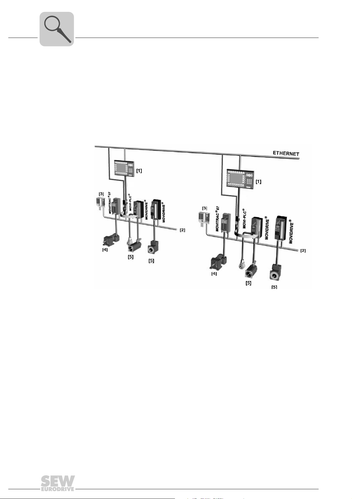
Use as a standalone machine controller
You can also use the MOVI-PLC
®
advanced DH.41B controller as a control unit for an
entire machine.
If used without a higher-level PLC, the MOVI-PLC
®
advanced DH.41B controller takes
over all control tasks, including controlling drives and other actuators, as well as evaluating decentralized inputs and outputs.
In a stand-alone topology, operator terminals (DOP11B) function as the interface between the operator and machine.
You can connect MOVI-PLC
®
advanced DH.41B directly to the company’s Ethernet net-
work.
ETHERNET
ETHERNET
RS485
RS485
Figure 1: Example of a topology when using MOVI-PLC® advanced DH.41B as the standalone
control for a complete machine
60544AXX
[1] Operator terminal (e.g. DOP11B drive operator panel)
[2] System bus (CAN 1, CAN 2, Ethernet 1)
[3] Inputs and outputs (terminals)
[4] Asynchronous motor
[5] Synchronous servomotor/asynchronous servomotor
10
Manual – MOVI-PLC® advanced DHE41B/DHF41B/DHR41B Controller
Introduction
MOVI-PLC® advanced DH.41B controller
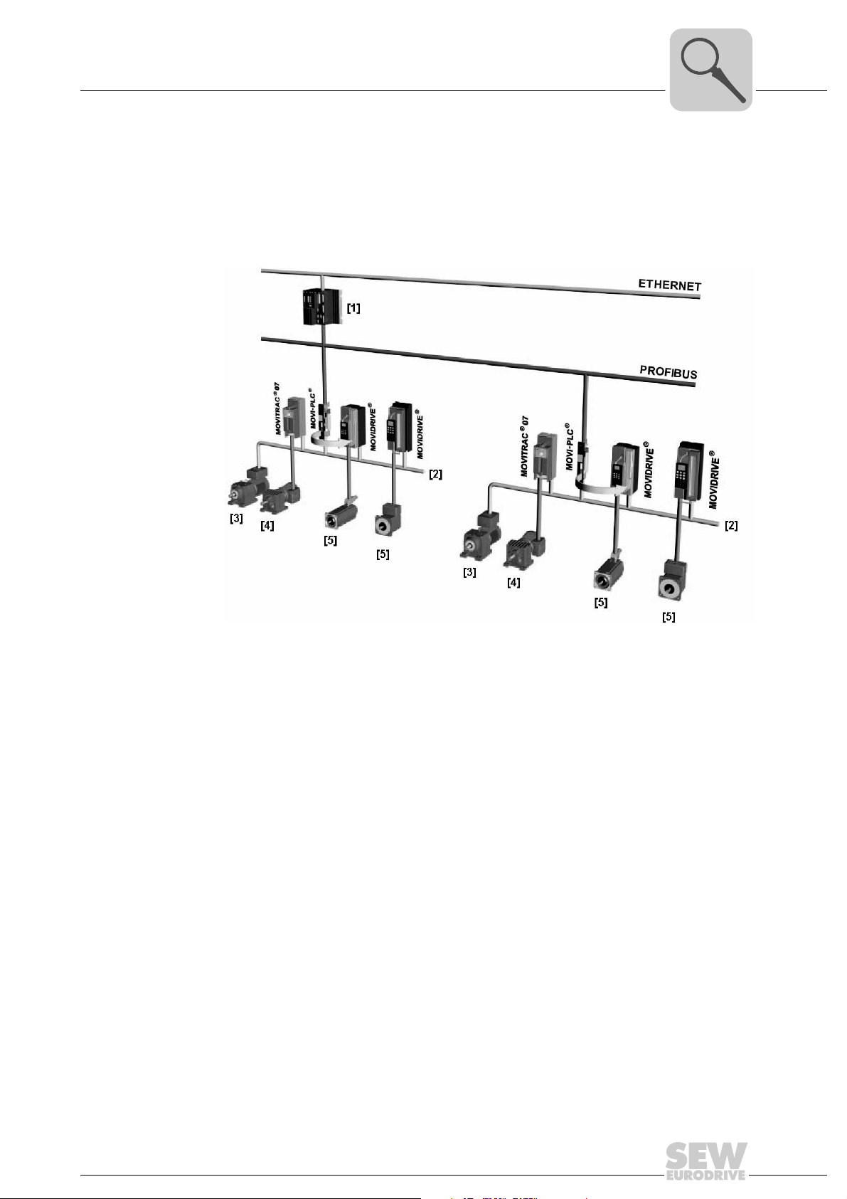
Use as a module controller
You can also use the MOVI-PLC
mation of a machine module (→ following figure). In this way, the MOVI-PLC
DH.41B controller coordinates motion sequences in the axis system.
The controller is connected to a higher-level PLC via the PROFIBUS interface or via one
of the integrated fieldbus interfaces.
®
advanced DH.41B controller for decentralized auto-
®
advanced
3
Figure 2: Example of a topology for controlling each machine module using
a MOVI-PLC
®
advanced DH.41B controller
[1] Higher-level PLC
[2] System bus (CAN 1, CAN 2)
[3] MOVIMOT
MOVI-PLC
®
(via fieldbus interface DeviceNet MFD.../connected directly to
®
via RS485 interface COM2)
[4] Asynchronous motor
[5] Synchronous servomotor/asynchronous servomotor
58621AXX
Manual – MOVI-PLC® advanced DHE41B/DHF41B/DHR41B Controller
11

3
Introduction
MOVI-PLC® advanced DH.41B controller
System buses CAN 1, CAN 2 and Ethernet 1
Configuring the PROFIBUS interface
You can use the MOVI-PLC® advanced DH.41B controller to control a machine module
by coupling several inverters via the system bus. In this way, MOVI-PLC
®
advanced
DH.41B controls all the drives within the machine module and in doing so takes off load
from the master controller (e.g. machine or system PLC). You can connect a maximum
of 64 of the following units to the MOVI-PLC
®
advanced DH.41B controller via system
buses CAN 1, CAN 2 and Ethernet 1:
•MOVITRAC
•MOVIDRIVE
•MOVIAXIS
• Gearmotor with integrated frequency inverter MOVIMOT
®
B frequency inverter
®
MDX60B/61B drive inverter
®
servo inverter
®
(Fieldbus interface
DeviceNet MFD... required)
The PROFIBUS station address is set using the DIP switches on the front of the
MOVI-PLC
®
advanced DH.41B controller. This manual setting means the MOVI-PLC
advanced DH.41B controller can be integrated into the PROFIBUS environment and
switched on within a very short period of time. The higher-level PROFIBUS master can
set the parameters automatically (parameter download).
This option offers the following advantages:
• Less time required to start up the system
• Simple documentation of the application program as all important parameter data
can be transferred from the program of the higher-level controller.
®
Cyclical and acyclical data exchange
via PROFIBUS DP
Cyclical and acyclical data exchange
via PROFIBUS
DP-V1
PROFIBUS monitoring functions
While process data is usually exchanged cyclically, drive parameters are read or written
acyclically using functions such as Read and Write or via the MOVILINK
®
parameter
channel. This parameter data exchange enables you to implement applications in which
all the important drive parameters are stored in the master programmable controller, so
that there is no need to make parameter settings manually on the inverter itself.
The PROFIBUS DP-V1 specification introduced new acyclical Read/Write services within the context of the PROFIBUS DP-V1 expansions. These acyclical services are inserted in special telegrams during cyclical bus operation to ensure compatibility between
PROFIBUS DP (version 0) and PROFIBUS DP-V1 (version 1).
Using a fieldbus system requires additional monitoring functions for the drive technology, for example, time monitoring of the fieldbus (PROFIBUS timeout). The function module that addresses the PROFIBUS issues a PROFIBUS timeout using the relevant fault
information. This allows the application to respond to the PROFIBUS timeout.
12
Manual – MOVI-PLC® advanced DHE41B/DHF41B/DHR41B Controller

Introduction
MOVI-PLC® advanced DH.41B controller
3
RS485 interfaces COM1 and COM2
Ethernet 2 You can implement the following functions and connections via the communication
Binary inputs and outputs
Diagnostics The LEDs of the MOVI-PLC
Connect one of the following devices each to the RS485 interfaces COM1 or COM2:
• DOP11B operator terminal
• Gearmotor with integrated frequency inverter MOVIMOT
interface Ethernet 2:
• Engineering
• Connection of a DOP11B operator terminal
• For visualization (for example: OPC interface)
• Connection to master level
Binary inputs and outputs enable you to switch actuators (e.g. valves) and evaluate binary input signals (e.g. sensors). You can freely use the binary inputs and outputs in the
PLC Editor of the MOVITOOLS
• Power supply of binary inputs and outputs
• General status of the MOVI-PLC
• Status of the control program
• Status of the PROFIBUS interface
• Status of the DeviceNet interface
• Status of the Ethernet interface
• Status of both CAN interfaces
You can connect operator terminals to perform diagnostics. It is recommended to connect an operator terminal to the communication interface Ethernet 2.
®
MotionStudio software in programming.
®
advanced DH.41B controller indicate the following states:
®
advanced DH.41B controller
®
Manual – MOVI-PLC® advanced DHE41B/DHF41B/DHR41B Controller
13
4
Mounting/Installation Instructions
Mounting options for the MOVI-PLC® advanced DH.41B controller
4 Mounting/Installation Instructions
4.1 Mounting options for the MOVI-PLC® advanced DH.41B controller
Observe the following mounting instructions:
NOTES
• You can insert the MOVI-PLC® advanced DH.41B controller in the
MOVIDRIVE
• Option cards can only be installed or removed for MOVIDRIVE
drive inverters sizes 1 to 6.
• Only SEW-EURODRIVE engineers may install or remove option cards for
MOVIDRIVE
• Only SEW-EURODRIVE engineers may install or remove MOVI-PLC
advanced DH.41B controllers for MOVIAXIS® as well as install MOVI-PLC
DH.41B/UOH..B compact controllers.
®
MDX61B inverter, but not in the MOVIDRIVE® MDX60B inverter.
®
MDX61B size 0 drive inverters.
®
MDX61B
®
®
4.2 Mounting MOVI-PLC® advanced DH.41B in MOVIDRIVE® MDX61B
• The MOVI-PLC® advanced DHE41B controller must be plugged into the fieldbus slot
of the MOVIDRIVE
DHE41B option into the expansion slot.
• The MOVI-PLC
expansion slot of the MOVIDRIVE
MDX61B size 0.
Before you begin Observe the following notes before installing or removing the MOVI-PLC
advanced DH.41B controller:
• Disconnect the drive inverter from power. Switch off the DC 24 V and the line voltage.
• Take appropriate measures to avoid electrostatic charges (use discharge strap, conductive shoes, etc.) before touching the MOVI-PLC
• Before installing the MOVI-PLC
and the front cover.
• After installing the MOVI-PLC
and the front cover.
• Keep the MOVI-PLC
mediately before you are ready to install it.
• Hold the MOVI-PLC
any components.
• Never place the MOVI-PLC
®
MDX61B. If the fieldbus slot is not available, you can plug the
®
advanced DHF41B/DHR41B controller must be plugged into the
®
advanced DH.41B controller in its original packaging until im-
®
advanced DH.41B controller by its edges only. Do not touch
®
MDX61B. It cannot be installed in MOVIDRIVE
®
advanced DH.41B.
®
advanced DH.41B controller, remove the keypad
®
advanced DH.41B controller, replace the keypad
®
advanced DH.41B controller on a conductive surface.
®
®
14
Manual – MOVI-PLC® advanced DHE41B/DHF41B/DHR41B Controller
Mounting/Installation Instructions
Mounting MOVI-PLC® advanced DH.41B in MOVIDRIVE® MDX61B
Basic procedure for installing and removing an option card in/from MOVIDRIVE® MDX61B
2.
1.
3.
4
4.
53001AXX
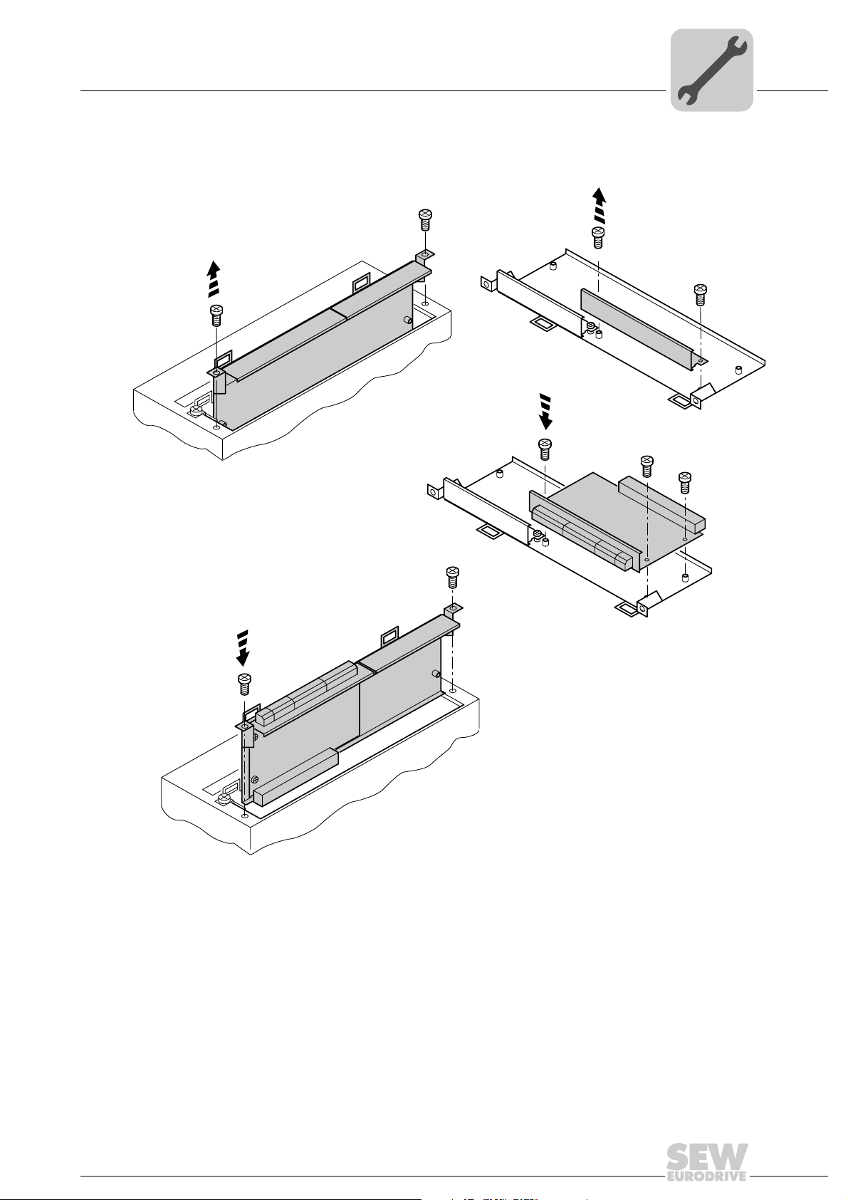
1. Remove the retaining screws holding the card retaining bracket. Pull the card retaining bracket out evenly from the slot (do not twist).
2. Remove the retaining screws of the black cover plate on the card retaining bracket.
Remove the black cover plate.
3. Position the option card onto the retaining bracket so that the retaining screws fit into
the corresponding bores on the card retaining bracket.
4. Insert the retaining bracket with installed option card into the slot, pressing slightly so
it is seated properly. Secure the card retaining bracket with the retaining screws.
5. Follow the instructions in reverse order when removing the option card.
Manual – MOVI-PLC® advanced DHE41B/DHF41B/DHR41B Controller
15
4
Mounting/Installation Instructions
Installing the MOVI-PLC® advanced DHE41B controller
4.3 Installing the MOVI-PLC® advanced DHE41B controller
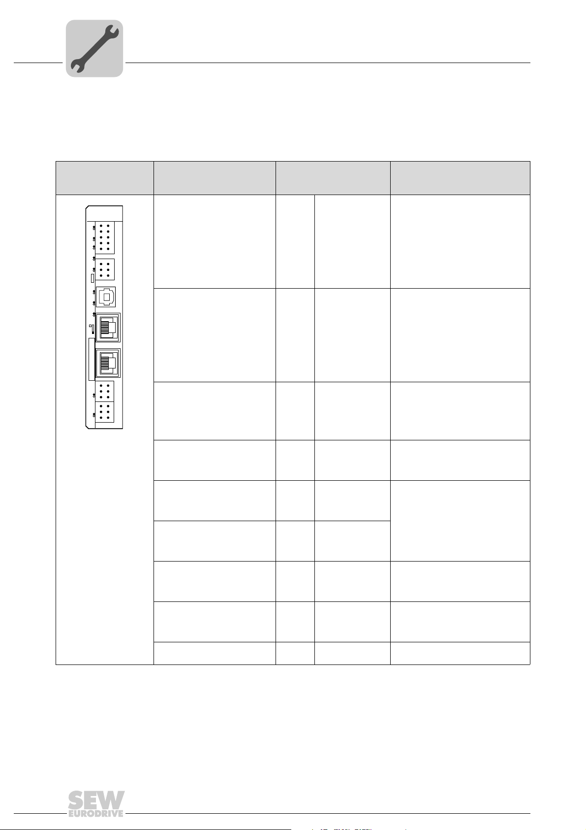
4.3.1 Function description of the terminals, DIP switches and LEDs
Front view
MOVI-PLC
®
advanced
controller DHE41B
DHE41B
2
1
4
3
6
5
8107
X31
9
2
1
4
3
X34
6
5
X35
T1
342
1
X36
S1
X37
1
1
2
2
X32X33
3
3
1
1
2
2
3
3
L1 L2 L3 L5XM L6 L7 L8 L9L4 L1 0
60108AXX
LED
Designation
DIP switches
Ter min al
LED LED 1
LED 2
LED 3
LED 4
LED 5
LED 6
LED 7
LED 8
LED 9
LED10
Terminal X31:
Binary inputs and outputs
(plug-in terminals)
X31:1
X31:2
X31:3
X31:4
X31:5
X31:6
X31:7
X31:8
X31:9
X31:10
Terminal X34:
RS485 interfaces COM1,
COM2
(plug-in terminals)
X34:1
X34:2
X34:3
X34:4
X34:5
X34:6
Connector X35:
USB connection
(In preparation)
X35:1
X35:2
X35:3
X35:4
Connector X36:
X36
Connection Ethernet 1
System bus (RJ45 socket)
Connector X37:
X37
Connection Ethernet 2
(RJ45 socket)
CAN 1 status
CAN 2 status
IEC progr. status
PLC status
User LED
DIO6/7
DIO4/5
DIO2/3
DIO0/1
24 V / I/O OK
+24 V input
REF24V
DIO 0
DIO 1
DIO 2
DIO 3
DIO 4
DIO 5
DIO 6
DIO 7
RS+
RS+ insulated
RS–
RS– insulated
DGND
GND insulated
USB+5 V
USB–
USB+
DGND
Function
Status of CAN 1 system bus
Status of CAN 2 system bus
Status of control program
Status of control firmware
Freely programmable
Status input or output DIO 6/7
Status input or output DIO 4/5
Status input or output DIO 2/3
Status input or output DIO 0/1
Status of voltage supply I/O
Voltage input DC+24 V
Reference potential for binary signals
Binary input or output (DIO 0)
Binary input or output (DIO 1)
Binary input or output (DIO 2)
Binary input or output (DIO 3)
Binary input or output (DIO 4)
Binary input or output (DIO 5)
Binary input or output (DIO 6)
Binary input or output (DIO 7)
Signal RS485+ (COM 1)
Signal RS485+ insulated (COM 2)
Signal RS485– (COM 1)
Signal RS485– insulated (COM 2)
Reference potential (COM 1)
Reference potential (COM 2)
DC 5 V power supply
Signal USB–
Signal USB+
Reference potential
Standard Ethernet assignment
16
Terminal X32:
System bus CAN 2
(electrically isolated)
X32:1
X32:2
X32:3
(plug-in terminals)
Terminal X33:
System bus CAN 1
(plug-in terminals)
X33:1
X33:2
X33:3
DIP switch S1
Manual – MOVI-PLC® advanced DHE41B/DHF41B/DHR41B Controller
REF_CAN 2
CAN 2H
CAN 2L
DGND
CAN 1H
CAN 1L
To p
Bottom
Reference potential for system bus
CAN 2
System bus CAN 2 high
System bus CAN 2 low
Reference potential for system bus
CAN 1
System bus CAN 1 high
System bus CAN 1 low
Default IP address (192.168.10.4)
Ethernet 2 connection
Mounting/Installation Instructions
Installing the MOVI-PLC® advanced DHE41B controller
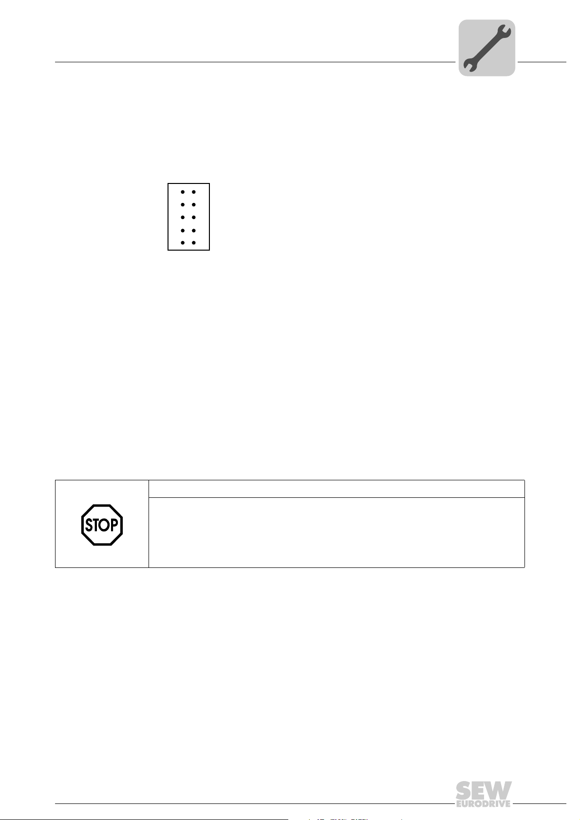
4.3.2 Connection of binary inputs and outputs (connector X31)
Connector X31 provides 8 binary inputs or outputs (e.g. for controlling external actuators/sensors).
You can define the binary inputs and outputs in the PLC editor of the MOVITOOLS
MotionStudio software.
2
1
3
4
5
X31
6
7
8
9
10
4
®
Figure 3: 12-pin connector for connecting binary inputs and outputs
61018AXX
Binary inputs • The binary inputs are electrically isolated by optocouplers.
• The permitted input voltages are defined according to IEC 61131.
+13 V ... +30 V = "1" = Contact closed
–3 V ... +5 V = "0" = Contact open
Interrupt inputs • You can use binary inputs X31:6 to X31:10 as interrupt inputs. The response time
until the ISR (interrupt service routine) is processed is less than 100 ms.
Binary outputs • The binary outputs are electrically isolated by optocouplers.
• The binary outputs are short-circuit proof but not interference-voltage-proof.
• The maximum permitted output current is 150 mA per binary output. All eight binary
outputs can be operated simultaneously with this current.
STOP!
The supply voltage must be present on X31:1/2 for using the binary inputs and outputs.
The MOVI-PLC
binary inputs and outputs is no longer ensured.
If the supply voltage is stopped, you must turn off all other current supplies to X31:1 ...
10, e.g. the DC 24 V from switches and sensors at the binary inputs.
®
controller can be damaged. In this case, the specified function of the
• To avoid the danger of maximum voltage peaks, you may not connect inductive loads
to the supply voltage or to the binary inputs or outputs without free-wheeling diodes.
Cable specification • Only connect cables with a minimum core cross section of 0.25 mm
a maximal core cross section of 1 mm
2
(AWG18). IEC 60999 does allow clamping
without conductor end sleeves.
• Choose the type and core cross section of the connected cable in dependency of the
required cable length and the load expected from your application.
For more information on binary inputs or outputs, refer to chapter "Technical Data" on
page 61.
Manual – MOVI-PLC® advanced DHE41B/DHF41B/DHR41B Controller
2
(AWG23) and
17
4
Mounting/Installation Instructions
Installing the MOVI-PLC® advanced DHE41B controller
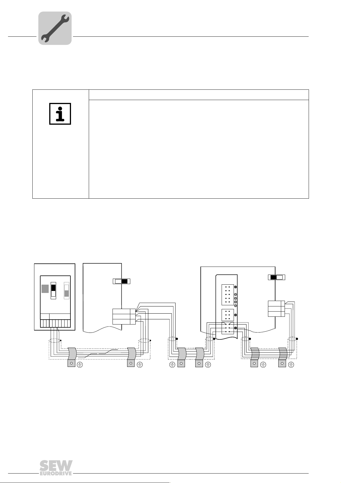
4.3.3 Connecting system bus CAN 2 (connector X32) / CAN 1 (connector X33)
Do not connect more than 64 units to the CAN 2 or CAN 1 system bus. The system bus
supports the address range 0 ... 63.
NOTES
• The CAN 2 system bus is electrically isolated. Therefore, it is recommended to use
the CAN 2 (X32) interface for connecting field devices (e.g. CANopen inputs and
outputs).
• The CAN 1 system bus is not electrically isolated. Therefore, it is recommended to
use the CAN 1 (X33) interface to connect inverters via the system bus in the control
cabinet.
• SEW-EURODRIVE recommends connecting a maximum of 64 inputs and 64 outputs via I/O modules to the MOVI-PLC
• No CAN system bus connection is necessary for communication between MOVID-
®
RIVE
MDX61B and its installed controller MOVI-PLC® advanced if you use the
'DPRAM' channel (→ "MOVI-PLC
al). A CAN system bus connection is, however, necessary if modules from the
MPLCMotion_MDX and MPLCprocessdata libraries are employed.
®
basic DHP11B.. controller.
®
Programming in the PLC Editor" system manu-
The CAN system bus supports transmission systems compliant with ISO 11898. The
Serial Communication manual contains detailed information about the CAN system bus.
This manual can be ordered from SEW-EURODRIVE.
Wiring diagram for CAN 2 system bus
MOVITRAC® B
S1
S2
ON
OFF
X44
FSC11B
X46
X45
7
23456HL ⊥
1
Figure 4: CAN 2 system bus connection taking the example of a MOVIDRIVE® MDX60B/61B / MOVITRAC® B inverter
MDX60B/61B
X12
ON OFF
DGND
SC11
SC12
S12
1
2
3
MDX61B
DHE41B
X31X32X33
1
2
3
1
2
3
ON OFF
X12:
DGND
1
2
3
1
2
3
SC11
SC12
S12
1
2
3
60526AXX
Cable specification • Use a 2x2-core twisted and shielded copper cable (data transmission cable with
braided copper shield). IEC 60999 does allow clamping without conductor end
sleeves. The cable must meet the following specifications:
– Core cross section 0.2 ... 1.0 mm
2
(AWG 24 ... AWG 18)
– Line resistance 120 Ω at 1 MHz
– Capacitance per unit length ≤ 40 pF/m at 1 kHz
Suitable cables include CAN bus or DeviceNet cables.
18
Manual – MOVI-PLC® advanced DHE41B/DHF41B/DHR41B Controller
Mounting/Installation Instructions
Installing the MOVI-PLC® advanced DHE41B controller
Cable length • The permitted total cable length depends on the baud rate setting of the system bus:
– 125 kbaud → 500 m
– 250 kbaud → 250 m
– 500 kBaud → 100 m
– 1000 kbaud → 40 m
Terminating
resistor
• Switch on the system bus terminating resistor at the start and end of the CAN 2 system bus connection (MOVIDRIVE
®
B, DIP switch S12 = ON; MOVITRAC® B, DIP
switch S1 = ON). For all other devices, switch off the terminating resistor
(MOVIDRIVE
the MOVI-PLC
®
B, DIP switch S12 = OFF; MOVITRAC® B, DIP switch S1 = OFF). If
®
advanced DH.41B controller is, for example, located at the end of
the CAN 2 system bus, you have to connect a terminating resistor of 120 O between
pins X32:2 and X32:3 (for CAN 1: terminating resistor between pins X33:2 and pin
X33:3).
STOP!
•There must not be any potential displacement between the units connected via the
CAN 2 system bus.
•There must not be any potential displacement between the units connected via the
CAN 1 system bus.
• Take suitable measures to avoid potential displacement, such as connecting the
unit ground connectors using a separate cable.
4
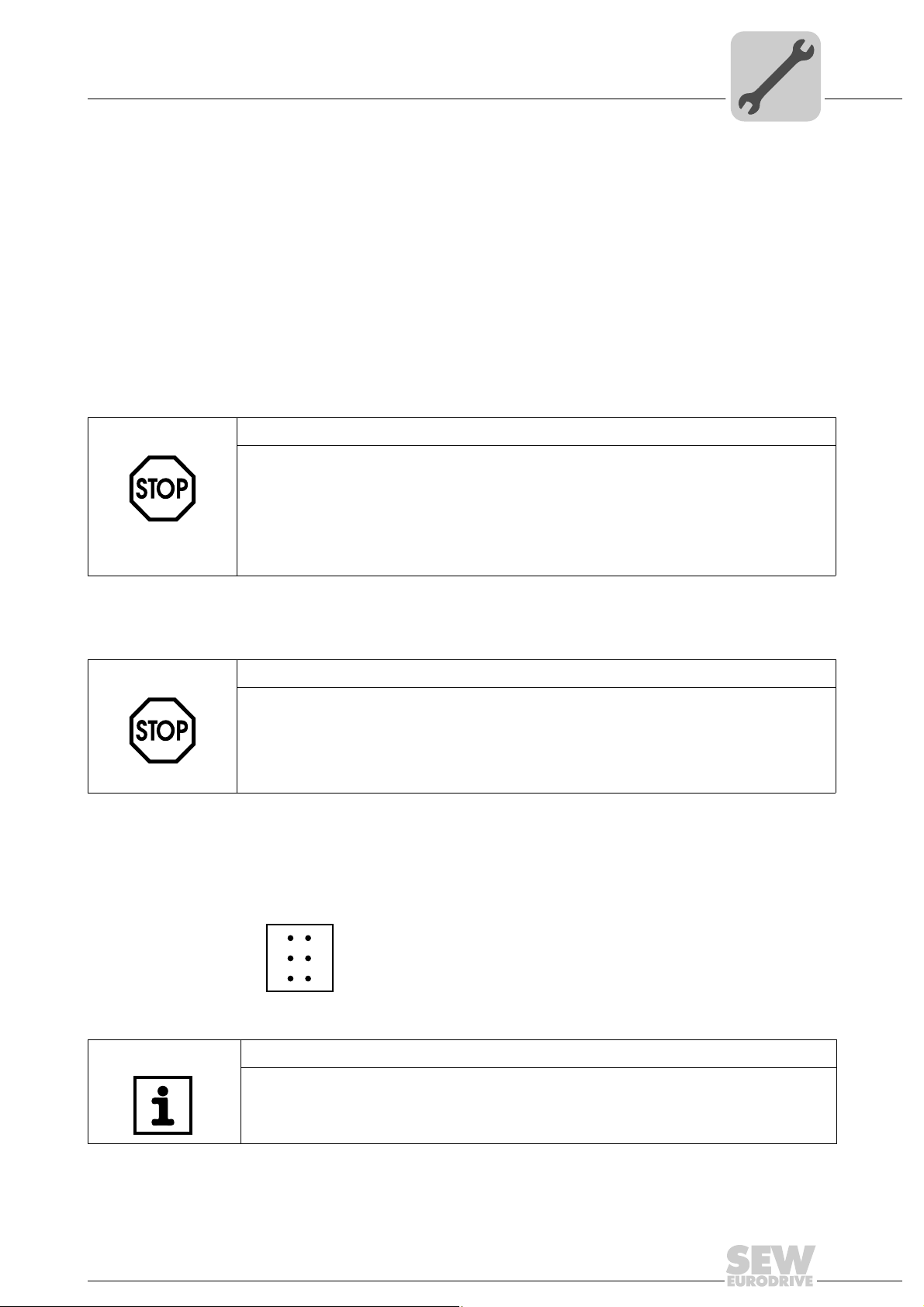
4.3.4 Connection of the RS485 interface (connector X34)
STOP!
• There must not be any potential displacement between the units connected via the
RS485. Take suitable measures to avoid a potential displacement, e.g. by connecting the unit ground connectors using a separate lead.
• Dynamic terminating resistors are installed. Do not connect any external termi-
nating resistors.
You can connect one of the following devices to the RS485 interfaces COM1/2 (connector X34):
• DOP11A operator terminals
• Gearmotor with integrated frequency inverter MOVIMOT
2
1
3
X34
Figure 5: 6-pole connector for connecting the RS485 interfaces COM1/2
4
5
6
NOTE
For more information on how to connect the DOP11B operator terminal, refer to the
chapters "Installation" and "Pin assignment" in the "DOP11B Operator Terminals" system manual.
®
63207AXX
Manual – MOVI-PLC® advanced DHE41B/DHF41B/DHR41B Controller
19
4
Mounting/Installation Instructions
Installing the MOVI-PLC® advanced DHE41B controller
4.3.5 Connecting the Ethernet 1 system bus (connector X36)
The Ethernet 1 interface (connector X36) is reserved for the system bus.
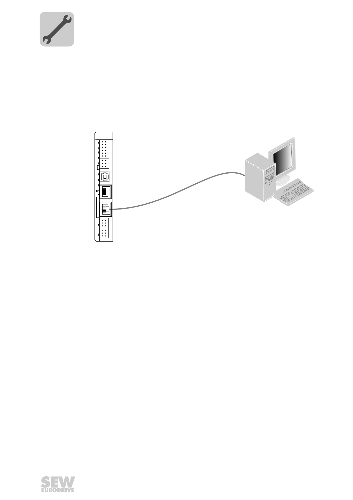
4.3.6 Connection of the Ethernet 2 interface (connector X37)
You can connect an engineering PC to the Ethernet 2 interface (connector X37).
DHE41B
2
1
4
3
6
5
8
7
10
9
12
11
2
1
4
3
6
5
X35
T1
342
1
X36
S1
X37
1
1
2
2
3
3
1
1
2
2
3
3
L1 L2 L3 L5XM L6 L7 L8 L9L4 L1 0
X31
X34
X32X33
PC COM
Figure 6: Example: Connecting an engineering PC via the Ethernet 2 interface to X37
Using the Ethernet 2 interface, the MOVI-PLC
®
advanced DHE41B controller can also
exchange data via UDP/TCP with another controller.
61522AXX
20
Manual – MOVI-PLC® advanced DHE41B/DHF41B/DHR41B Controller
Mounting/Installation Instructions
Installing the MOVI-PLC® advanced DHE41B controller
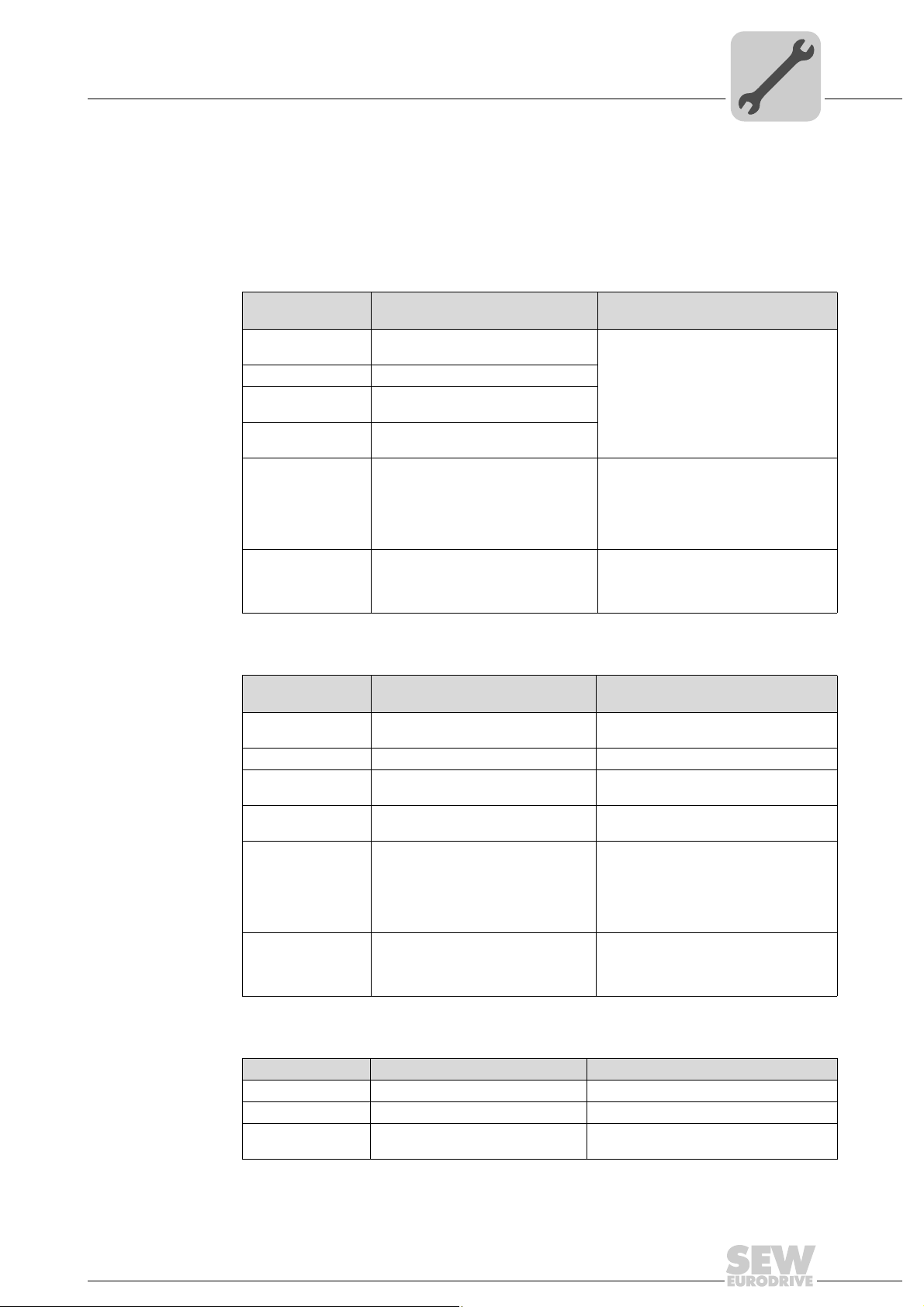
4.3.7 Operating displays of the MOVI-PLC® advanced DHE41B controller
®
The MOVI-PLC
current status of the MOVI-PLC
advanced DHE41B controller has 10 LEDs (L1 ... L10) that display the
®
advanced DHE41B controller and its interfaces.
4
LED L1 (CAN 1 status)
LED L2 (CAN 2 status)
The LED L1 indicates the status of the CAN 1 system bus.
Status of the LED L1Diagnostics Troubleshooting
Orange The CAN 1 system bus is being initial-
Green The CAN 1 system bus is initialized.
Flashing green
(0,5 Hz)
Flashing green
(1 Hz)
Red The CAN 1 system bus is off (BUS-
Flashing red
(1 Hz)
ized.
The CAN 1 system bus is currently in
SCOM suspend mode.
The CAN 1 system bus is currently in
SCOM On mode.
OFF).
Warning on the CAN 1 system bus. 1. Check and correct the cabling of the
-
1. Check and correct the cabling of the
CAN 1 system bus.
2. Check and correct the baud rate set
for the CAN 1 system bus.
3. Check and correct the terminating
resistors of the CAN 1 system bus.
CAN 1 system bus.
2. Check and correct the baud rate set
for the CAN 1 system bus.
The LED L2 indicates the status of the CAN 2 system bus.
Status of the LED L2Diagnostics Troubleshooting
Orange The CAN 2 system bus is being initial-
Green The CAN 2 system bus is initialized. -
Flashing green
(0,5 Hz)
Flashing green
(1 Hz)
Red The CAN 2 system bus is off (BUS-
Flashing red
(1 Hz)
ized.
The CAN 2 system bus is currently in
SCOM suspend mode.
The CAN 2 system bus is currently in
SCOM On mode.
OFF).
Warning on the CAN 2 system bus. 1. Check and correct the cabling of the
-
-
-
1. Check and correct the cabling of the
CAN 2 system bus.
2. Check and correct the baud rate set
for the CAN 2 system bus.
3. Check and correct the terminating
resistors of the CAN 2 system bus.
CAN 2 system bus.
2. Check and correct the baud rate set
for the CAN 2 system bus.
LED L3 (IEC program status)
The LED L3 indicates the status of the IEC-61131 control program.
Status of L3 Diagnostics Troubleshooting
Green IEC program is running. -
Off No program is loaded. Load a program into the controller.
Flashing orange (1
Hz)
Program has stopped. Bootloader update required (see chapter
Manual – MOVI-PLC® advanced DHE41B/DHF41B/DHR41B Controller
"SD memory card type OMH41B-T.")
21
4
Mounting/Installation Instructions
Installing the MOVI-PLC® advanced DHE41B controller
LED L4 (PLC status)
The LED L4 indicates the status of the firmware of the MOVI-PLC® advanced
DHE41B controller.
Status of the LED L4Diagnostics Troubleshooting
Flashing green
(1 Hz)
Red • No SD card plugged in.
Flashing orange
(1 Hz)
The firmware of the MOVI-PLC
advanced DHE41B controller is running correctly.
• File system of the SC card corrupt
Program has stopped. Bootloader update required (see chapter
®
-
"SD memory card type OMH41B-T.")
LED L5 (user) The LED L5 is freely programmable in the IEC program.
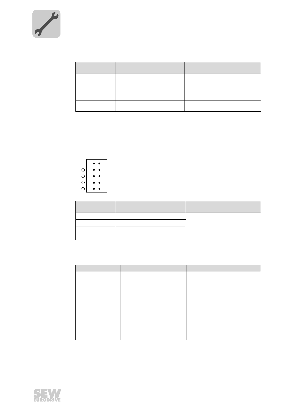
LED L6, L7, L8, L9 (DIO n/m)
The LEDs L6, L7, L8, L9 indicate the status of the binary inputs and outputs (X31:3
- X31:10) n or m (e. g. DIO2/3).
nm
2
1
3
L9
L8
L7
L6
4
5
6
8
10
X31
7
9
63437AXX
LED L10 (24V / I/O OK)
State of the LEDs
L6, L7, L8, L9
Off No voltage present.
Green Voltage at LED n.
Red Voltage at LED m.
Orange Voltage at LED n. and m.
Diagnostics Troubleshooting
-
The LED L10 indicates the status of the voltage supply for binary inputs and
outputs.
Status of the LED L10 Diagnostics Troubleshooting
Green Voltage supply for the binary
inputs/outputs is OK.
Off Voltage supply for the binary
inputs/outputs is not applied.
Orange Voltage supply for the binary
inputs/outputs is applied. However,
one of the following faults has
occurred:
• Overload on one or several
binary inputs/outputs
• Overtemperature of the output
driver
• Short circuit in at least one of
the binary inputs/outputs
-
1. Switch off the inverter in which the
MOVI-PLC
troller is installed.
2. Check and correct the cabling of the
binary inputs/outputs according to the
electrical wiring diagram.
3. Check current consumption of the
connected actuators (max. current →
chapter 8).
4. Switch on the inverter in which the
MOVI-PLC
troller is installed.
®
advanced DHE41B con-
®
advanced DHE41B con-
22
Manual – MOVI-PLC® advanced DHE41B/DHF41B/DHR41B Controller
 Loading...