

Drive Technology \ Drive Automation \ System Integration \ Services
MOVI-PLC
®
advanced
DHE41B/DHF41B/DHR41B Controller
Edition 04/2008
16623215 / EN
Manual

SEW-EURODRIVE – Driving the world

1 General Notes......................................................................................................... 5
1.1 Structure of the safety notes .......................................................................... 5
1.2 Right to claim under warranty ........................................................................ 5
1.3 Exclusion of liability ........................................................................................ 6
1.4 Copyright notice ............................................................................................. 6
2 Safety Notes ........................................................................................................... 7
2.1 Other applicable documentation .................................................................... 7
2.2 Safety functions ............................................................................................. 7
2.3 Hoist applications ........................................................................................... 7
2.4 Disposal ......................................................................................................... 7
3 Introduction ............................................................................................................ 8
3.1 MOVI-PLC
3.2 MOVI-PLC
®
– Motion Control with integrated control technology.................. 8
®
advanced DH.41B controller...................................................... 9
4 Mounting/Installation Instructions...................................................................... 14
4.1 Mounting options for the MOVI-PLC
4.2 Mounting MOVI-PLC
4.3 Installing the MOVI-PLC
®
advanced DH.41B in MOVIDRIVE® MDX61B ......... 14
®
advanced DHE41B controller ............................. 16
®
advanced DH.41B controller............ 14
4.3.1 Function description of the terminals, DIP switches and LEDs ......... 16
4.3.2 Connection of binary inputs and outputs (connector X31) ................ 17
4.3.3 Connecting system bus CAN 2 (connector X32) / CAN 1
(connector X33) ................................................................................ 18
4.3.4 Connection of the RS485 interface (connector X34) ........................ 19
4.3.5 Connecting the Ethernet 1 system bus (connector X36) .................. 20
4.3.6 Connection of the Ethernet 2 interface (connector X37) ................... 20
4.3.7 Operating displays of the MOVI-PLC
®
advanced DHE41B
controller ........................................................................................... 21
4.3.8 DIP switch S1 default IP address ...................................................... 23
4.3.9 SD memory card type OMH41B-T. ................................................... 23
4.4 Installing the MOVI-PLC
®
advanced DHF41B controller ............................. 24
4.4.1 Function description of the terminals, DIP switches and LEDs ......... 24
4.4.2 PROFIBUS connection (connector X30P) ........................................ 26
4.4.3 Connecting DeviceNet (connector X30D) ......................................... 27
4.4.4 Connecting SafetyBus (connector X38) ............................................ 28
4.4.5 Operating displays of MOVI-PLC
4.5 Installing the MOVI-PLC
®
advanced DHR41B controller............................. 32
®
advanced DHF41B .................... 29
4.5.1 Function description of the terminals, DIP switches and LEDs ......... 32
4.5.2 Pin assignment ................................................................................. 34
4.5.3 Shielding and routing bus cables ...................................................... 35
4.5.4 Setting the DIP switches 20 and 21 .................................................. 35
4.5.5 TCP / IP addressing and subnetworks .............................................. 36
4.5.6 Operating displays of the MOVI-PLC
®
advanced DHR41B
controller in PROFINET mode .......................................................... 38
4.5.7 Setting the IP address parameters via DCP ..................................... 40
4.5.8 Operating displays of the MOVI-PLC
®
advanced DHR41B
controller in EtherNet/IP mode .......................................................... 41
4.5.9 Setting the IP address parameters ................................................... 43
4.5.10 The integrated Ethernet switch ........................................................ 45
Manual – MOVI-PLC® advanced DHE41B/DHF41B/DHR41B Controller
3

4.6 Installation of the DH.41B option in MOVIDRIVE® MDX61B ....................... 46
4.7 Installation of the DH.41B option in the MOVIAXIS
®
MDX61B
master module ............................................................................................. 46
4.7.1 Function description of terminals X5a/X5b
(MOVIAXIS
4.8 Installing the DH.41B option in MOVITRAC
®
master module) ........................................................... 46
®
B/compact controller............. 48
4.8.1 Function description of terminals and LEDs ..................................... 48
4.8.2 Connection of RS485 interface COM 1 (connector X24) .................. 48
4.8.3 Connection of system bus CAN 1/power supply (connector X26) .... 49
4.8.4 MOVITRAC
4.9 Engineering interface of the MOVI-PLC
®
B/compact controller option slot operating displays .... 50
®
advanced DH.41B controller....... 51
4.10 Shielding and routing bus cables ................................................................. 51
5 Project Planning and Startup .............................................................................. 52
5.1 Configuration with the MOVITOOLS
®
MotionStudio PC software ............... 52
5.2 Configuration and startup of the drives ........................................................ 58
5.3 Configuration and startup in the PLC Editor................................................. 58
5.4 Replacing the unit ........................................................................................ 58
6 Error Diagnostics ................................................................................................. 59
6.1 Diagnostic procedure for system bus CAN 1/CAN 2.................................... 59
6.2 Diagnostic procedure for PROFIBUS-DP .................................................... 60
7 Technical Data and Dimension Drawings .......................................................... 61
7.1 General technical data ................................................................................. 61
7.2 MOVI-PLC
7.3 MOVI-PLC
7.4 MOVI-PLC
7.5 MOVI-PLC
7.6 Dimension drawings of MOVI-PLC
®
advanced DHE41B controller .................................................. 62
®
advanced DHF41B controller .................................................. 64
®
advanced DHR41B controller .................................................. 65
®
advanced compact controllers................................................. 65
®
advanced DH.41B/UOH..B ................ 66
7.6.1 DHE41B/UOH11B dimension drawing .............................................. 66
7.6.2 DHF/DHR41B/UOH21B dimension drawing ..................................... 67
8 Index...................................................................................................................... 68
4
Manual – MOVI-PLC® advanced DHE41B/DHF41B/DHR41B Controller
General Notes
Structure of the safety notes
1
1 General Notes
Manual
1.1 Structure of the safety notes
The safety notes in this manual are designed as follows:
Symbol SIGNAL WORD!
Nature and source of hazard.
Possible consequence(s) if disregarded.
• Measure(s) to avoid the hazard.
Symbol Signal word Meaning Consequences if
disregarded
Example:
General hazard
HAZARD! Imminent hazard Severe or fatal injuries
WARNING! Possible hazardous situation Severe or fatal injuries
CAUTION! Possible hazardous situation Minor injuries
Specific hazard,
e.g. electric shock
STOP! Possible damage to property Damage to the drive system or its environ-
NOTE Useful information or tip.
Simplifies handling of the drive
system.
1.2 Right to claim under warranty
A requirement of fault-free operation and fulfillment of any rights to claim under limited
warranty is that you adhere to the information in the documentation. Therefore, read the
manual before you start operating the device!
Make sure that the manual is available to persons responsible for the plant and its operation, as well as to persons who work independently on the device. You must also
ensure that the documentation is legible.
ment
Manual – MOVI-PLC® advanced DHE41B/DHF41B/DHR41B Controller
5

1
General Notes
Exclusion of liability
1.3 Exclusion of liability
1.4 Copyright notice
You must comply with the information contained in the MOVIDRIVE® documentation to
ensure safe operation and to achieve the specified product characteristics and performance requirements. SEW-EURODRIVE assumes no liability for injury to persons or
damage to equipment or property resulting from non-observance of these operating instructions. In such cases, any liability for defects is excluded.
© 2007 – SEW-EURODRIVE. All rights reserved.
Any reproduction, modification, distribution or unintended use, in whole or in part, is
prohibited.
6
Manual – MOVI-PLC® advanced DHE41B/DHF41B/DHR41B Controller

2 Safety Notes
2.1 Other applicable documentation
Safety Notes
Other applicable documentation
2
• Only specialists are allowed to perform installation and startup observing relevant accident prevention regulations and the MOVIDRIVE
or MOVIAXIS
• Read through this manual carefully before you commence installation and startup of
the DH.41B option.
• As a prerequisite to fault-free operation and fulfillment of warranty claims, you must
adhere to the information in the documentation.
2.2 Safety functions
The MOVIDRIVE® MDX60B/61B drive inverters may not perform safety functions without higher-level safety systems. Use higher-level safety systems to ensure protection of
equipment and personnel. For safety applications, ensure that the information in the following publications is observed: "Safe Disconnection for MOVIDRIVE
2.3 Hoist applications
MOVIDRIVE® MDX60B/61B, MOVITRAC® B and MOVIAXIS® are not designed for use
as a safety device in hoist applications.
Use monitoring systems or mechanical protection devices as safety features to avoid
possible damage to property or injury to people.
®
operating instructions!
®
MDX60B/61B, MOVITRAC® B
®
MDX60B/61B".
2.4 Disposal
Observe current national regulations.
Dispose of the following materials separately in accordance with the country-specific
regulations in force, as:
• Electronics scrap
• Plastics
• Sheet metal
• Copper
Manual – MOVI-PLC® advanced DHE41B/DHF41B/DHR41B Controller
7

3
3 Introduction
Introduction
MOVI-PLC® – Motion Control with integrated control technology
Content of this
manual
Additional
documentation
This user manual describes:
• Installation of the MOVI-PLC
®
advanced DH.41B controller in MOVIDRIVE
MDX61B
• The interfaces and LEDs of the MOVI-PLC
• Installation of the MOVI-PLC
®
advanced DH.41B controller in the MOVIDRIVE
®
advanced DH.41B controller
MDX61B and MOVITRAC® B inverters, in the MOVIAXIS® servo inverter and as a
compact controller
• The engineering access to the MOVI-PLC
• The project planning and startup of the MOVI-PLC
®
advanced DH.41B controller
®
advanced DH.41B controller and
of the controlled inverters and servo boosters
®
To configure and startup the MOVI-PLC
advanced DH.41B controller simply and effec-
tively, you should also request the following publications in addition to this manual:
•"MOVI-PLC
®
advanced DHF41B Fieldbus Interfaces PROFIBUS DP-V1 and De-
viceNet" manual
•"MOVI-PLC
®
advanced DHR41B Fieldbus Interfaces PROFINET IO, EtherNet/IP,
Modbus TCP/IP" manual
•"MOVI-PLC
• "MPLCMotion_MDX and MPLCMotion_MX Libraries for MOVI-PLC
• "MPLCMotion_MC07 and MPLCMotion_MM Libraries for MOVI-PLC
•MOVIDRIVE
•MOVITRAC
•MOVIAXIS
The "MOVI-PLC
for IEC 61131-3 compliant MOVI-PLC
The library manuals describe the motion libraries for MOVI-PLC
MOVIDRIVE
®
Programming in the PLC Editor" system manual
®
" manual
®
" manual
®
MDX60/61B system manual
®
B system manual
®
system folder
®
Programming in the PLC Editor" system manual contains instructions
®
MDX60B/61B, MOVIAXIS®, MOVITRAC® B, and MOVIMOT® inverters.
®
programming.
®
to control the
®
®
3.1 MOVI-PLC® – Motion Control with integrated control technology
Characteristics MOVI-PLC® is a family of programmable logic controllers for inverters. It allows drive so-
lutions, logic processing and sequence controls to be automated simply and efficiently
using IEC 61131-3 compliant programming languages.
•MOVI-PLC
of SEW inverters and offers a simple upgrade to a more powerful MOVI-PLC
sion, thanks to its universal execution of the programs.
•MOVI-PLC
vanced, etc.) and modular software concepts (libraries for numerous applications).
•MOVI-PLC
chronous operation) and the control of demanding applications (such as material
handling).
8
®
is a universal solution because it is able to control the entire portfolio
®
is scalable due to several different hardware platforms (basic, ad-
®
is powerful due to extensive technologies (such as electronic cam, syn-
Manual – MOVI-PLC® advanced DHE41B/DHF41B/DHR41B Controller
®
ver-

Introduction
MOVI-PLC® advanced DH.41B controller
3
Control categories
•MOVI-PLC® basic DHP11B allows for coordinated single axis movements and integration of external inputs/outputs as well as drive operator panels (DOP). This makes
MOVI-PLC
®
basic DHP11B suitable for the task of module controller and also for that
of stand-alone controller for machines of medium complexity.
•MOVI-PLC
higher performance, which allows complex calculations and, for example, interpolated movements. MOVI-PLC
®
advanced DH.41B is characterized by a greater variety of interfaces and
®
advanced is suitable for automating cells and ma-
chines. The integrated Ethernet interface allows for connecting MOVI-PLC
vanced directly to the control level.
3.2 MOVI-PLC® advanced DH.41B controller
Characteristics The MOVI-PLC® advanced DH.41B controller is available in two variants:
®
•As control card MOVI-PLC
and MOVITRAC
•As compact controller MOVI-PLC
a DIN rail. As a compact controller, it is designed for controlling inverters (→ chapter
"Technical Data").
Unit types The MOVI-PLC
ed fieldbus interfaces:
Unit design of MOVI-PLC®
advanced DH.41B
DHE41B Ethernet TCP/IP, UDP
DHF41B Ethernet TCP/IP, UDP, PROFIBUS DP-V1, DeviceNet
DHR41B Ethernet TCP/IP, UDP, PROFINET, EtherNet/IP, ModbusTCP/IP
®
B inverters and for MOVIAXIS® servo inverters
®
advanced DH.41B is available in 3 variants, which differ in the integrat-
advanced DH.41B as an option for MOVIDRIVE® B
®
advanced DH.41B prepared for installation on
Fieldbus interfaces
®
ad-
Engineering The engineering of the MOVI-PLC
activities:
• Configuration
• Parameterization
• Programming
These activities are carried out using the MOVITOOLS
ware. The software has a number of useful features for startup and diagnostics of all
SEW-EURODRIVE units. The connection between the MOVI-PLC
controller and the engineering PC is established via the Ethernet 2 communication interface.
Communication interfaces
The MOVI-PLC
tion interfaces.
®
advanced controller DH.41B is equipped with numerous communica-
The two system bus interfaces CAN 1 and CAN 2 are used primarily for connection, controlling several inverters and integrating decentralized I/O modules.
This machine module can be operated via the integrated fieldbus interface with a higherlevel controller.
Engineering is performed via the integrated Ethernet 2 communication interface.
An operator terminal (e.g. DOP11B) or a gearmotor with integrated MOVIMOT
frequency inverter are connected to the RS485 interfaces.
®
advanced DH.41B controller includes the following
®
MotionStudio engineering soft-
®
advanced DH.41B
®
Manual – MOVI-PLC® advanced DHE41B/DHF41B/DHR41B Controller
9
3
Introduction
MOVI-PLC® advanced DH.41B controller
Automation topologies
Use as a standalone machine controller
You can also use the MOVI-PLC
®
advanced DH.41B controller as a control unit for an
entire machine.
If used without a higher-level PLC, the MOVI-PLC
®
advanced DH.41B controller takes
over all control tasks, including controlling drives and other actuators, as well as evaluating decentralized inputs and outputs.
In a stand-alone topology, operator terminals (DOP11B) function as the interface between the operator and machine.
You can connect MOVI-PLC
®
advanced DH.41B directly to the company’s Ethernet net-
work.
ETHERNET
ETHERNET
RS485
RS485
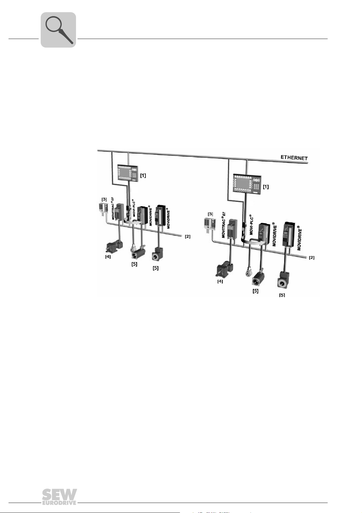
Figure 1: Example of a topology when using MOVI-PLC® advanced DH.41B as the standalone
control for a complete machine
60544AXX
[1] Operator terminal (e.g. DOP11B drive operator panel)
[2] System bus (CAN 1, CAN 2, Ethernet 1)
[3] Inputs and outputs (terminals)
[4] Asynchronous motor
[5] Synchronous servomotor/asynchronous servomotor
10
Manual – MOVI-PLC® advanced DHE41B/DHF41B/DHR41B Controller
Introduction
MOVI-PLC® advanced DH.41B controller
Use as a module controller
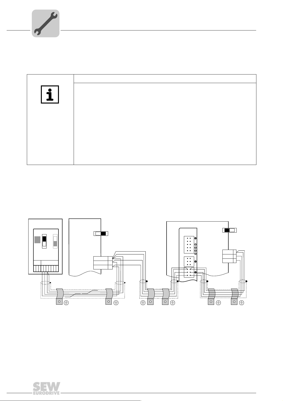
You can also use the MOVI-PLC
mation of a machine module (→ following figure). In this way, the MOVI-PLC
DH.41B controller coordinates motion sequences in the axis system.
The controller is connected to a higher-level PLC via the PROFIBUS interface or via one
of the integrated fieldbus interfaces.
®
advanced DH.41B controller for decentralized auto-
®
advanced
3
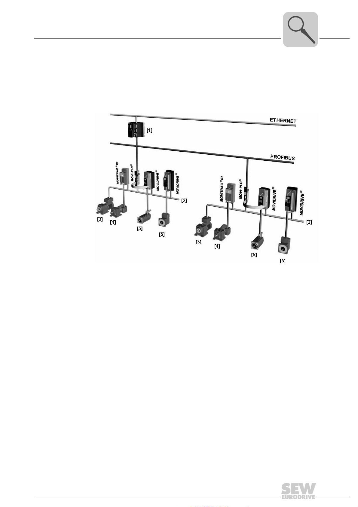
Figure 2: Example of a topology for controlling each machine module using
a MOVI-PLC
®
advanced DH.41B controller
[1] Higher-level PLC
[2] System bus (CAN 1, CAN 2)
[3] MOVIMOT
MOVI-PLC
®
(via fieldbus interface DeviceNet MFD.../connected directly to
®
via RS485 interface COM2)
[4] Asynchronous motor
[5] Synchronous servomotor/asynchronous servomotor
58621AXX
Manual – MOVI-PLC® advanced DHE41B/DHF41B/DHR41B Controller
11

3
Introduction
MOVI-PLC® advanced DH.41B controller
System buses CAN 1, CAN 2 and Ethernet 1
Configuring the PROFIBUS interface
You can use the MOVI-PLC® advanced DH.41B controller to control a machine module
by coupling several inverters via the system bus. In this way, MOVI-PLC
®
advanced
DH.41B controls all the drives within the machine module and in doing so takes off load
from the master controller (e.g. machine or system PLC). You can connect a maximum
of 64 of the following units to the MOVI-PLC
®
advanced DH.41B controller via system
buses CAN 1, CAN 2 and Ethernet 1:
•MOVITRAC
•MOVIDRIVE
•MOVIAXIS
• Gearmotor with integrated frequency inverter MOVIMOT
®
B frequency inverter
®
MDX60B/61B drive inverter
®
servo inverter
®
(Fieldbus interface
DeviceNet MFD... required)
The PROFIBUS station address is set using the DIP switches on the front of the
MOVI-PLC
®
advanced DH.41B controller. This manual setting means the MOVI-PLC
advanced DH.41B controller can be integrated into the PROFIBUS environment and
switched on within a very short period of time. The higher-level PROFIBUS master can
set the parameters automatically (parameter download).
This option offers the following advantages:
• Less time required to start up the system
• Simple documentation of the application program as all important parameter data
can be transferred from the program of the higher-level controller.
®
Cyclical and acyclical data exchange
via PROFIBUS DP
Cyclical and acyclical data exchange
via PROFIBUS
DP-V1
PROFIBUS monitoring functions
While process data is usually exchanged cyclically, drive parameters are read or written
acyclically using functions such as Read and Write or via the MOVILINK
®
parameter
channel. This parameter data exchange enables you to implement applications in which
all the important drive parameters are stored in the master programmable controller, so
that there is no need to make parameter settings manually on the inverter itself.
The PROFIBUS DP-V1 specification introduced new acyclical Read/Write services within the context of the PROFIBUS DP-V1 expansions. These acyclical services are inserted in special telegrams during cyclical bus operation to ensure compatibility between
PROFIBUS DP (version 0) and PROFIBUS DP-V1 (version 1).
Using a fieldbus system requires additional monitoring functions for the drive technology, for example, time monitoring of the fieldbus (PROFIBUS timeout). The function module that addresses the PROFIBUS issues a PROFIBUS timeout using the relevant fault
information. This allows the application to respond to the PROFIBUS timeout.
12
Manual – MOVI-PLC® advanced DHE41B/DHF41B/DHR41B Controller

Introduction
MOVI-PLC® advanced DH.41B controller
3
RS485 interfaces COM1 and COM2
Ethernet 2 You can implement the following functions and connections via the communication
Binary inputs and outputs
Diagnostics The LEDs of the MOVI-PLC
Connect one of the following devices each to the RS485 interfaces COM1 or COM2:
• DOP11B operator terminal
• Gearmotor with integrated frequency inverter MOVIMOT
interface Ethernet 2:
• Engineering
• Connection of a DOP11B operator terminal
• For visualization (for example: OPC interface)
• Connection to master level
Binary inputs and outputs enable you to switch actuators (e.g. valves) and evaluate binary input signals (e.g. sensors). You can freely use the binary inputs and outputs in the
PLC Editor of the MOVITOOLS
• Power supply of binary inputs and outputs
• General status of the MOVI-PLC
• Status of the control program
• Status of the PROFIBUS interface
• Status of the DeviceNet interface
• Status of the Ethernet interface
• Status of both CAN interfaces
You can connect operator terminals to perform diagnostics. It is recommended to connect an operator terminal to the communication interface Ethernet 2.
®
MotionStudio software in programming.
®
advanced DH.41B controller indicate the following states:
®
advanced DH.41B controller
®
Manual – MOVI-PLC® advanced DHE41B/DHF41B/DHR41B Controller
13
4
Mounting/Installation Instructions
Mounting options for the MOVI-PLC® advanced DH.41B controller
4 Mounting/Installation Instructions
4.1 Mounting options for the MOVI-PLC® advanced DH.41B controller
Observe the following mounting instructions:
NOTES
• You can insert the MOVI-PLC® advanced DH.41B controller in the
MOVIDRIVE
• Option cards can only be installed or removed for MOVIDRIVE
drive inverters sizes 1 to 6.
• Only SEW-EURODRIVE engineers may install or remove option cards for
MOVIDRIVE
• Only SEW-EURODRIVE engineers may install or remove MOVI-PLC
advanced DH.41B controllers for MOVIAXIS® as well as install MOVI-PLC
DH.41B/UOH..B compact controllers.
®
MDX61B inverter, but not in the MOVIDRIVE® MDX60B inverter.
®
MDX61B size 0 drive inverters.
®
MDX61B
®
®
4.2 Mounting MOVI-PLC® advanced DH.41B in MOVIDRIVE® MDX61B
• The MOVI-PLC® advanced DHE41B controller must be plugged into the fieldbus slot
of the MOVIDRIVE
DHE41B option into the expansion slot.
• The MOVI-PLC
expansion slot of the MOVIDRIVE
MDX61B size 0.
Before you begin Observe the following notes before installing or removing the MOVI-PLC
advanced DH.41B controller:
• Disconnect the drive inverter from power. Switch off the DC 24 V and the line voltage.
• Take appropriate measures to avoid electrostatic charges (use discharge strap, conductive shoes, etc.) before touching the MOVI-PLC
• Before installing the MOVI-PLC
and the front cover.
• After installing the MOVI-PLC
and the front cover.
• Keep the MOVI-PLC
mediately before you are ready to install it.
• Hold the MOVI-PLC
any components.
• Never place the MOVI-PLC
®
MDX61B. If the fieldbus slot is not available, you can plug the
®
advanced DHF41B/DHR41B controller must be plugged into the
®
advanced DH.41B controller in its original packaging until im-
®
advanced DH.41B controller by its edges only. Do not touch
®
MDX61B. It cannot be installed in MOVIDRIVE
®
advanced DH.41B.
®
advanced DH.41B controller, remove the keypad
®
advanced DH.41B controller, replace the keypad
®
advanced DH.41B controller on a conductive surface.
®
®
14
Manual – MOVI-PLC® advanced DHE41B/DHF41B/DHR41B Controller
Mounting/Installation Instructions
Mounting MOVI-PLC® advanced DH.41B in MOVIDRIVE® MDX61B
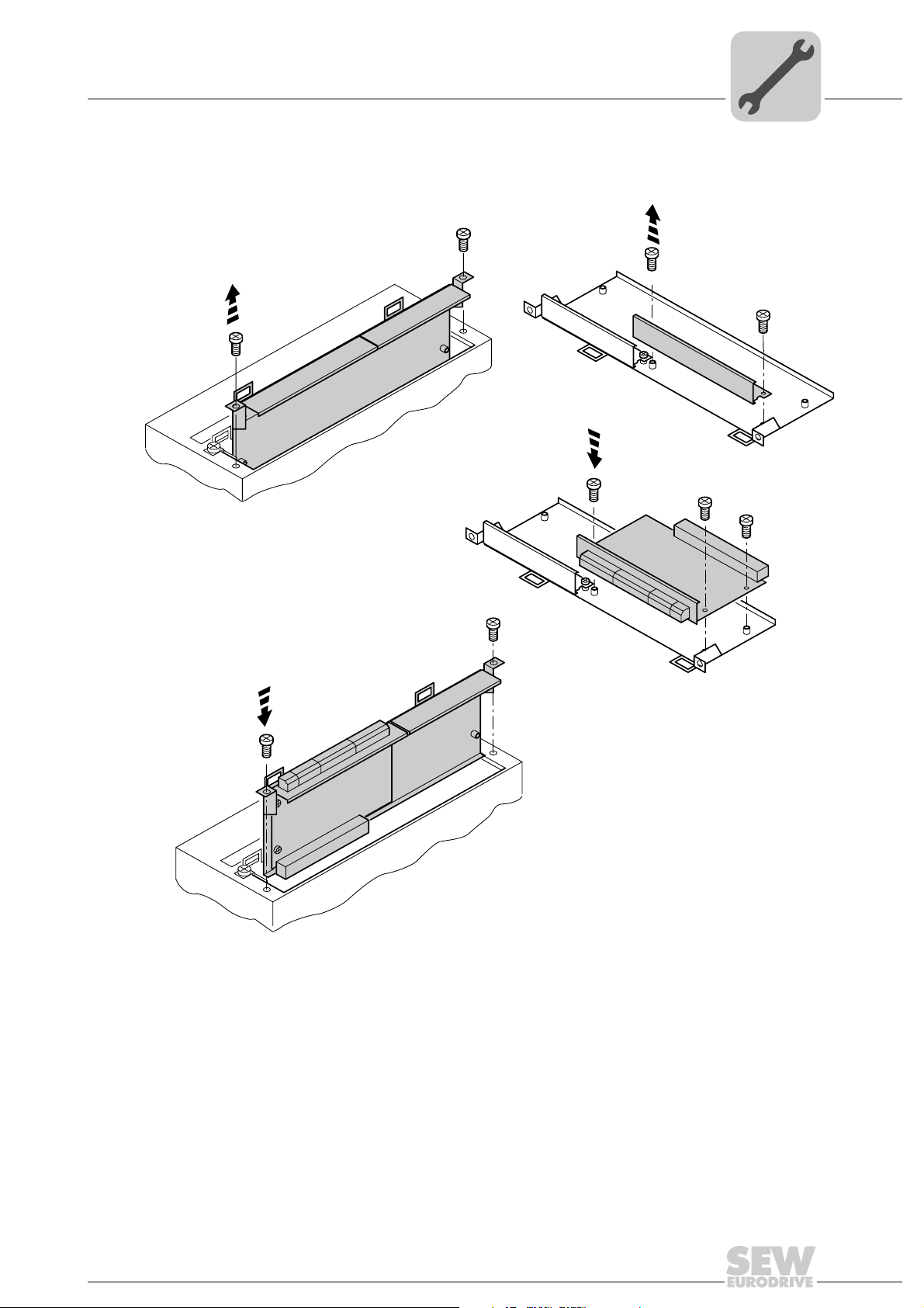
Basic procedure for installing and removing an option card in/from MOVIDRIVE® MDX61B
2.
1.
3.
4
4.
53001AXX
1. Remove the retaining screws holding the card retaining bracket. Pull the card retaining bracket out evenly from the slot (do not twist).
2. Remove the retaining screws of the black cover plate on the card retaining bracket.
Remove the black cover plate.
3. Position the option card onto the retaining bracket so that the retaining screws fit into
the corresponding bores on the card retaining bracket.
4. Insert the retaining bracket with installed option card into the slot, pressing slightly so
it is seated properly. Secure the card retaining bracket with the retaining screws.
5. Follow the instructions in reverse order when removing the option card.
Manual – MOVI-PLC® advanced DHE41B/DHF41B/DHR41B Controller
15
4
Mounting/Installation Instructions
Installing the MOVI-PLC® advanced DHE41B controller
4.3 Installing the MOVI-PLC® advanced DHE41B controller
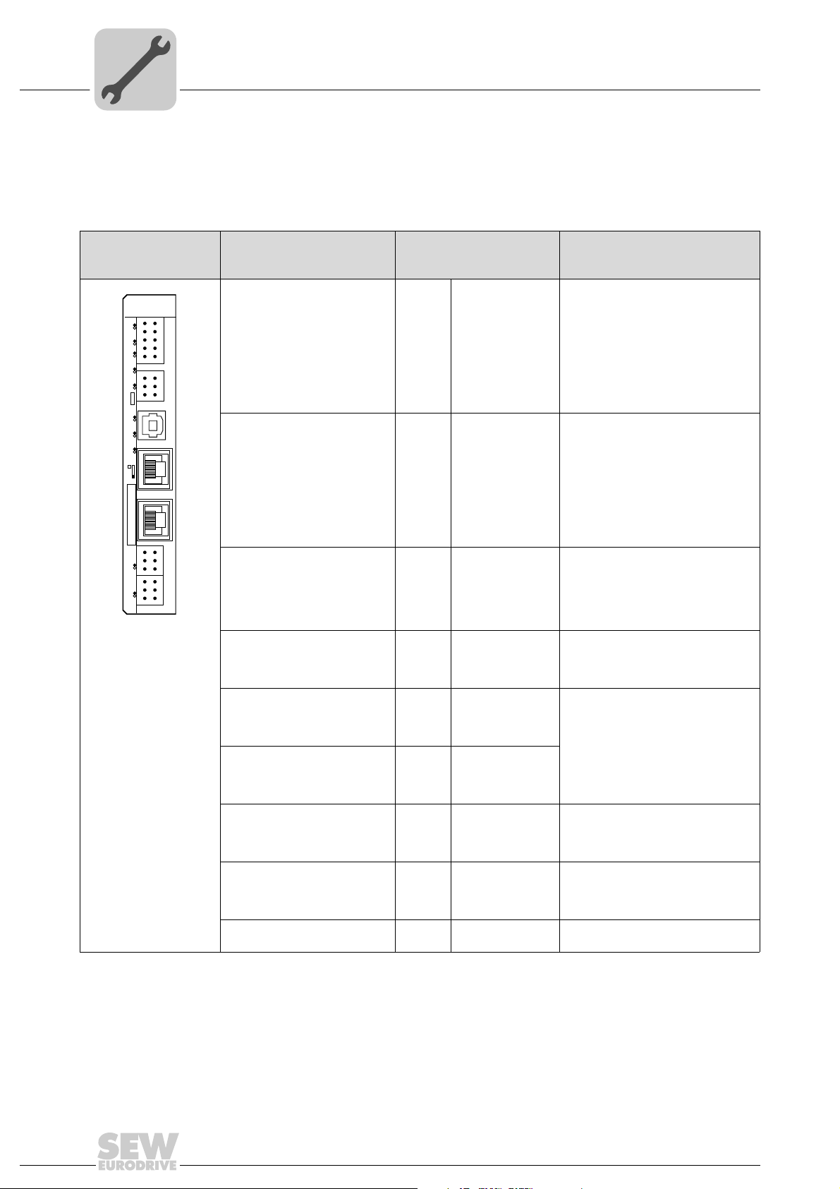
4.3.1 Function description of the terminals, DIP switches and LEDs
Front view
MOVI-PLC
®
advanced
controller DHE41B
DHE41B
2
1
4
3
6
5
8107
X31
9
2
1
4
3
X34
6
5
X35
T1
342
1
X36
S1
X37
1
1
2
2
X32X33
3
3
1
1
2
2
3
3
L1 L2 L3 L5XM L6 L7 L8 L9L4 L1 0
60108AXX
LED
Designation
DIP switches
Ter min al
LED LED 1
LED 2
LED 3
LED 4
LED 5
LED 6
LED 7
LED 8
LED 9
LED10
Terminal X31:
Binary inputs and outputs
(plug-in terminals)
X31:1
X31:2
X31:3
X31:4
X31:5
X31:6
X31:7
X31:8
X31:9
X31:10
Terminal X34:
RS485 interfaces COM1,
COM2
(plug-in terminals)
X34:1
X34:2
X34:3
X34:4
X34:5
X34:6
Connector X35:
USB connection
(In preparation)
X35:1
X35:2
X35:3
X35:4
Connector X36:
X36
Connection Ethernet 1
System bus (RJ45 socket)
Connector X37:
X37
Connection Ethernet 2
(RJ45 socket)
CAN 1 status
CAN 2 status
IEC progr. status
PLC status
User LED
DIO6/7
DIO4/5
DIO2/3
DIO0/1
24 V / I/O OK
+24 V input
REF24V
DIO 0
DIO 1
DIO 2
DIO 3
DIO 4
DIO 5
DIO 6
DIO 7
RS+
RS+ insulated
RS–
RS– insulated
DGND
GND insulated
USB+5 V
USB–
USB+
DGND
Function
Status of CAN 1 system bus
Status of CAN 2 system bus
Status of control program
Status of control firmware
Freely programmable
Status input or output DIO 6/7
Status input or output DIO 4/5
Status input or output DIO 2/3
Status input or output DIO 0/1
Status of voltage supply I/O
Voltage input DC+24 V
Reference potential for binary signals
Binary input or output (DIO 0)
Binary input or output (DIO 1)
Binary input or output (DIO 2)
Binary input or output (DIO 3)
Binary input or output (DIO 4)
Binary input or output (DIO 5)
Binary input or output (DIO 6)
Binary input or output (DIO 7)
Signal RS485+ (COM 1)
Signal RS485+ insulated (COM 2)
Signal RS485– (COM 1)
Signal RS485– insulated (COM 2)
Reference potential (COM 1)
Reference potential (COM 2)
DC 5 V power supply
Signal USB–
Signal USB+
Reference potential
Standard Ethernet assignment
16
Terminal X32:
System bus CAN 2
(electrically isolated)
X32:1
X32:2
X32:3
(plug-in terminals)
Terminal X33:
System bus CAN 1
(plug-in terminals)
X33:1
X33:2
X33:3
DIP switch S1
Manual – MOVI-PLC® advanced DHE41B/DHF41B/DHR41B Controller
REF_CAN 2
CAN 2H
CAN 2L
DGND
CAN 1H
CAN 1L
To p
Bottom
Reference potential for system bus
CAN 2
System bus CAN 2 high
System bus CAN 2 low
Reference potential for system bus
CAN 1
System bus CAN 1 high
System bus CAN 1 low
Default IP address (192.168.10.4)
Ethernet 2 connection
Mounting/Installation Instructions
Installing the MOVI-PLC® advanced DHE41B controller
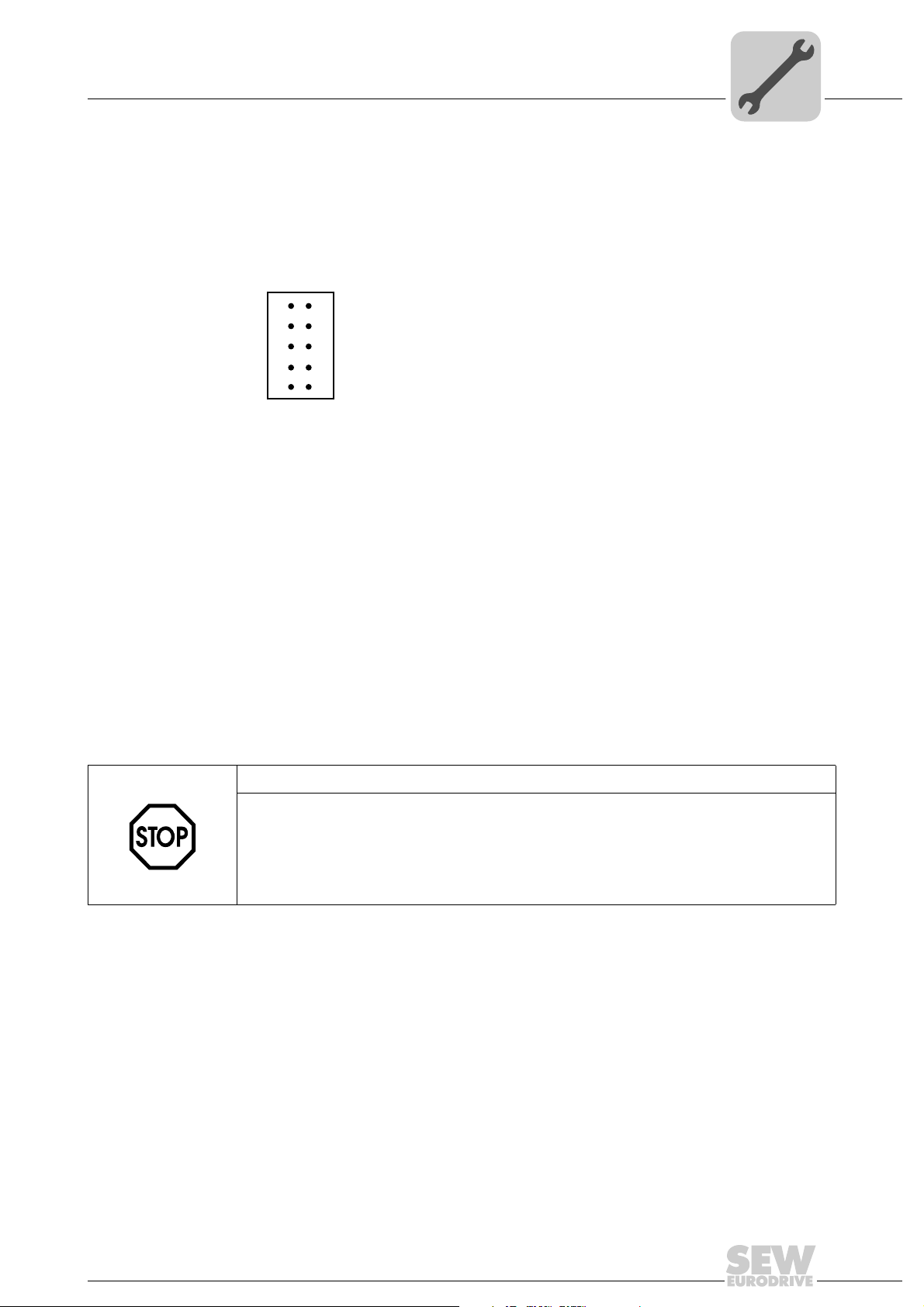
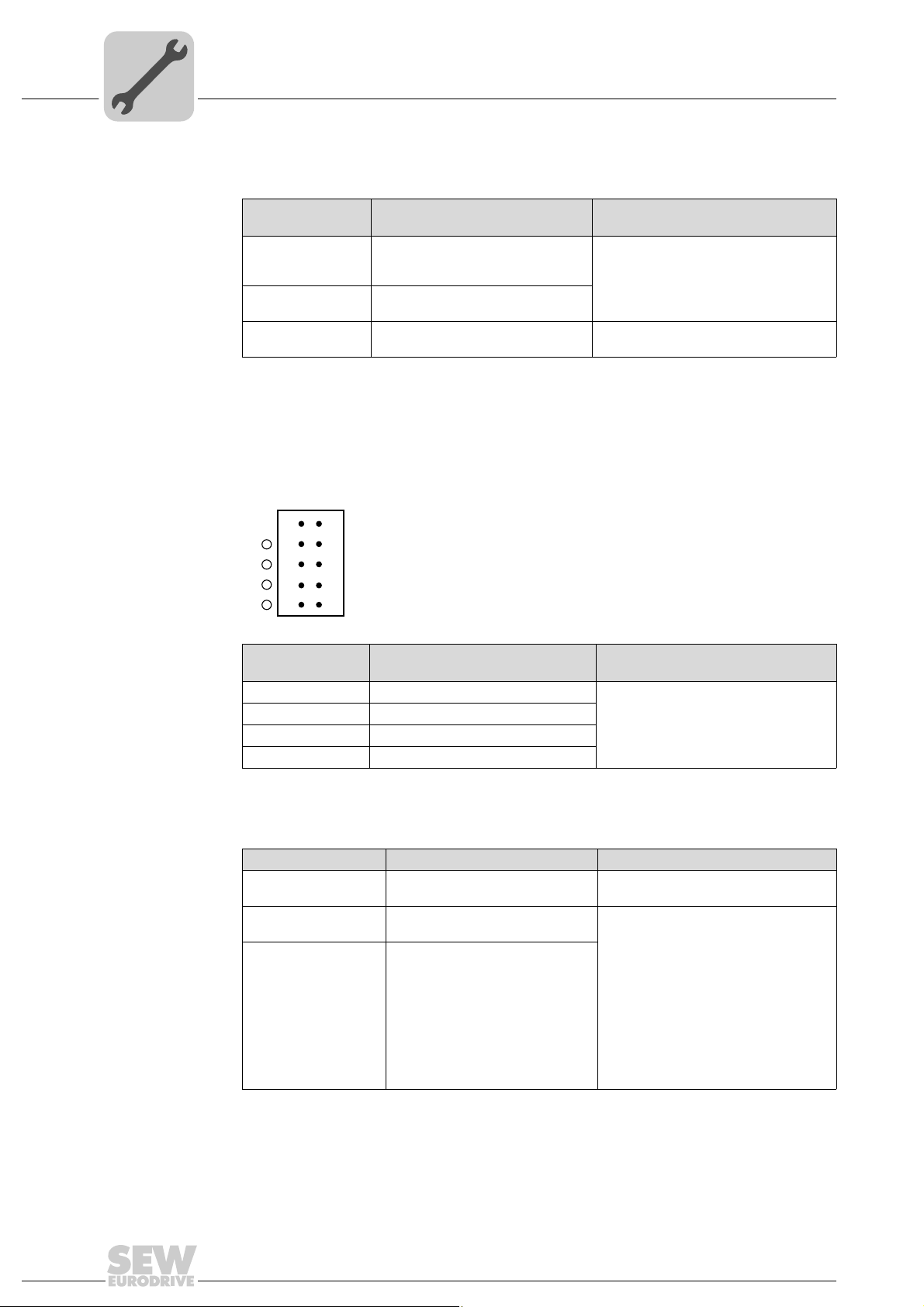
4.3.2 Connection of binary inputs and outputs (connector X31)
Connector X31 provides 8 binary inputs or outputs (e.g. for controlling external actuators/sensors).
You can define the binary inputs and outputs in the PLC editor of the MOVITOOLS
MotionStudio software.
2
1
3
4
5
X31
6
7
8
9
10
4
®
Figure 3: 12-pin connector for connecting binary inputs and outputs
61018AXX
Binary inputs • The binary inputs are electrically isolated by optocouplers.
• The permitted input voltages are defined according to IEC 61131.
+13 V ... +30 V = "1" = Contact closed
–3 V ... +5 V = "0" = Contact open
Interrupt inputs • You can use binary inputs X31:6 to X31:10 as interrupt inputs. The response time
until the ISR (interrupt service routine) is processed is less than 100 ms.
Binary outputs • The binary outputs are electrically isolated by optocouplers.
• The binary outputs are short-circuit proof but not interference-voltage-proof.
• The maximum permitted output current is 150 mA per binary output. All eight binary
outputs can be operated simultaneously with this current.
STOP!
The supply voltage must be present on X31:1/2 for using the binary inputs and outputs.
The MOVI-PLC
binary inputs and outputs is no longer ensured.
If the supply voltage is stopped, you must turn off all other current supplies to X31:1 ...
10, e.g. the DC 24 V from switches and sensors at the binary inputs.
®
controller can be damaged. In this case, the specified function of the
• To avoid the danger of maximum voltage peaks, you may not connect inductive loads
to the supply voltage or to the binary inputs or outputs without free-wheeling diodes.
Cable specification • Only connect cables with a minimum core cross section of 0.25 mm
a maximal core cross section of 1 mm
2
(AWG18). IEC 60999 does allow clamping
without conductor end sleeves.
• Choose the type and core cross section of the connected cable in dependency of the
required cable length and the load expected from your application.
For more information on binary inputs or outputs, refer to chapter "Technical Data" on
page 61.
Manual – MOVI-PLC® advanced DHE41B/DHF41B/DHR41B Controller
2
(AWG23) and
17
4
Mounting/Installation Instructions
Installing the MOVI-PLC® advanced DHE41B controller
4.3.3 Connecting system bus CAN 2 (connector X32) / CAN 1 (connector X33)
Do not connect more than 64 units to the CAN 2 or CAN 1 system bus. The system bus
supports the address range 0 ... 63.
NOTES
• The CAN 2 system bus is electrically isolated. Therefore, it is recommended to use
the CAN 2 (X32) interface for connecting field devices (e.g. CANopen inputs and
outputs).
• The CAN 1 system bus is not electrically isolated. Therefore, it is recommended to
use the CAN 1 (X33) interface to connect inverters via the system bus in the control
cabinet.
• SEW-EURODRIVE recommends connecting a maximum of 64 inputs and 64 outputs via I/O modules to the MOVI-PLC
• No CAN system bus connection is necessary for communication between MOVID-
®
RIVE
MDX61B and its installed controller MOVI-PLC® advanced if you use the
'DPRAM' channel (→ "MOVI-PLC
al). A CAN system bus connection is, however, necessary if modules from the
MPLCMotion_MDX and MPLCprocessdata libraries are employed.
®
basic DHP11B.. controller.
®
Programming in the PLC Editor" system manu-
The CAN system bus supports transmission systems compliant with ISO 11898. The
Serial Communication manual contains detailed information about the CAN system bus.
This manual can be ordered from SEW-EURODRIVE.
Wiring diagram for CAN 2 system bus
MOVITRAC® B
S1
S2
ON
OFF
X44
FSC11B
X46
X45
7
23456HL ⊥
1
Figure 4: CAN 2 system bus connection taking the example of a MOVIDRIVE® MDX60B/61B / MOVITRAC® B inverter
MDX60B/61B
X12
ON OFF
DGND
SC11
SC12
S12
1
2
3
MDX61B
DHE41B
X31X32X33
1
2
3
1
2
3
ON OFF
X12:
DGND
1
2
3
1
2
3
SC11
SC12
S12
1
2
3
60526AXX
Cable specification • Use a 2x2-core twisted and shielded copper cable (data transmission cable with
braided copper shield). IEC 60999 does allow clamping without conductor end
sleeves. The cable must meet the following specifications:
– Core cross section 0.2 ... 1.0 mm
2
(AWG 24 ... AWG 18)
– Line resistance 120 Ω at 1 MHz
– Capacitance per unit length ≤ 40 pF/m at 1 kHz
Suitable cables include CAN bus or DeviceNet cables.
18
Manual – MOVI-PLC® advanced DHE41B/DHF41B/DHR41B Controller
Mounting/Installation Instructions
Installing the MOVI-PLC® advanced DHE41B controller
Cable length • The permitted total cable length depends on the baud rate setting of the system bus:
– 125 kbaud → 500 m
– 250 kbaud → 250 m
– 500 kBaud → 100 m
– 1000 kbaud → 40 m
Terminating
resistor
• Switch on the system bus terminating resistor at the start and end of the CAN 2 system bus connection (MOVIDRIVE
®
B, DIP switch S12 = ON; MOVITRAC® B, DIP
switch S1 = ON). For all other devices, switch off the terminating resistor
(MOVIDRIVE
the MOVI-PLC
®
B, DIP switch S12 = OFF; MOVITRAC® B, DIP switch S1 = OFF). If
®
advanced DH.41B controller is, for example, located at the end of
the CAN 2 system bus, you have to connect a terminating resistor of 120 O between
pins X32:2 and X32:3 (for CAN 1: terminating resistor between pins X33:2 and pin
X33:3).
STOP!
•There must not be any potential displacement between the units connected via the
CAN 2 system bus.
•There must not be any potential displacement between the units connected via the
CAN 1 system bus.
• Take suitable measures to avoid potential displacement, such as connecting the
unit ground connectors using a separate cable.
4
4.3.4 Connection of the RS485 interface (connector X34)
STOP!
• There must not be any potential displacement between the units connected via the
RS485. Take suitable measures to avoid a potential displacement, e.g. by connecting the unit ground connectors using a separate lead.
• Dynamic terminating resistors are installed. Do not connect any external termi-
nating resistors.
You can connect one of the following devices to the RS485 interfaces COM1/2 (connector X34):
• DOP11A operator terminals
• Gearmotor with integrated frequency inverter MOVIMOT
2
1
3
X34
Figure 5: 6-pole connector for connecting the RS485 interfaces COM1/2
4
5
6
NOTE
For more information on how to connect the DOP11B operator terminal, refer to the
chapters "Installation" and "Pin assignment" in the "DOP11B Operator Terminals" system manual.
®
63207AXX
Manual – MOVI-PLC® advanced DHE41B/DHF41B/DHR41B Controller
19
4
Mounting/Installation Instructions
Installing the MOVI-PLC® advanced DHE41B controller
4.3.5 Connecting the Ethernet 1 system bus (connector X36)
The Ethernet 1 interface (connector X36) is reserved for the system bus.
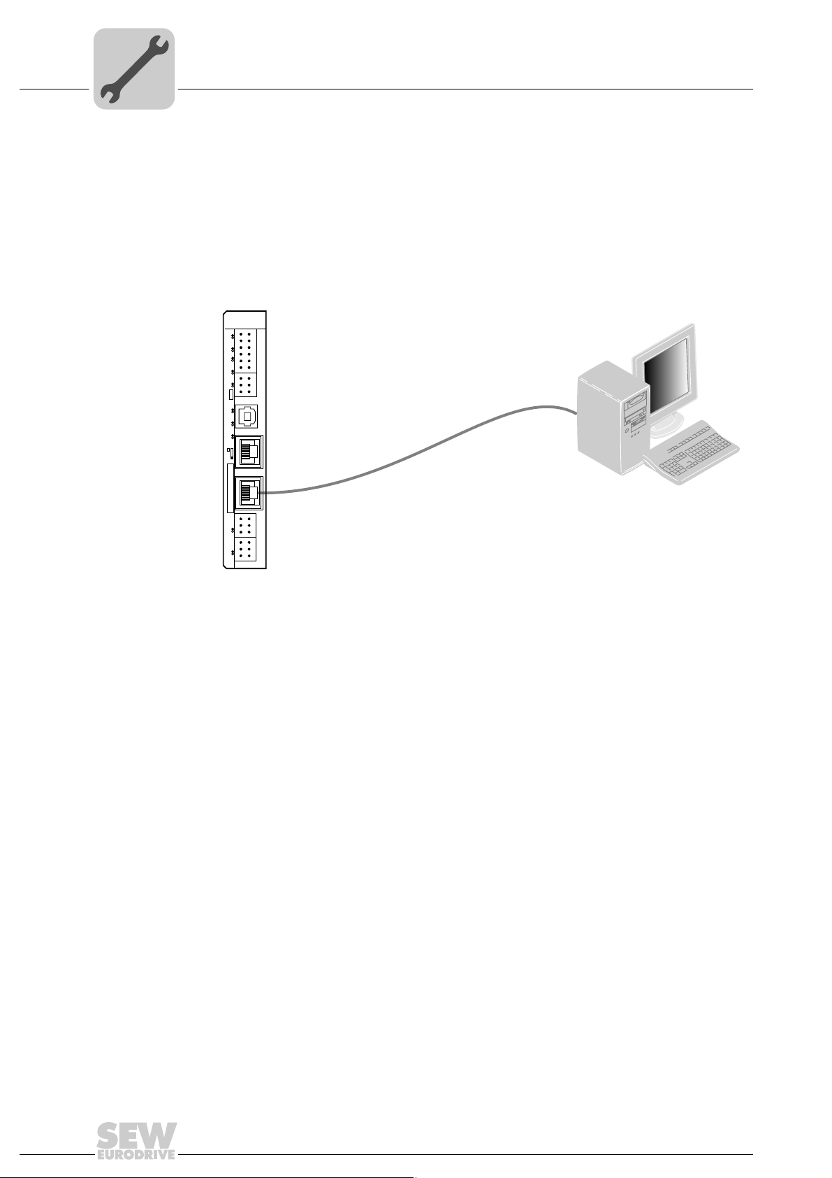
4.3.6 Connection of the Ethernet 2 interface (connector X37)
You can connect an engineering PC to the Ethernet 2 interface (connector X37).
DHE41B
2
1
4
3
6
5
8
7
10
9
12
11
2
1
4
3
6
5
X35
T1
342
1
X36
S1
X37
1
1
2
2
3
3
1
1
2
2
3
3
L1 L2 L3 L5XM L6 L7 L8 L9L4 L1 0
X31
X34
X32X33
PC COM
Figure 6: Example: Connecting an engineering PC via the Ethernet 2 interface to X37
Using the Ethernet 2 interface, the MOVI-PLC
®
advanced DHE41B controller can also
exchange data via UDP/TCP with another controller.
61522AXX
20
Manual – MOVI-PLC® advanced DHE41B/DHF41B/DHR41B Controller
Mounting/Installation Instructions
Installing the MOVI-PLC® advanced DHE41B controller
4.3.7 Operating displays of the MOVI-PLC® advanced DHE41B controller
®
The MOVI-PLC
current status of the MOVI-PLC
advanced DHE41B controller has 10 LEDs (L1 ... L10) that display the
®
advanced DHE41B controller and its interfaces.
4
LED L1 (CAN 1 status)
LED L2 (CAN 2 status)
The LED L1 indicates the status of the CAN 1 system bus.
Status of the LED L1Diagnostics Troubleshooting
Orange The CAN 1 system bus is being initial-
Green The CAN 1 system bus is initialized.
Flashing green
(0,5 Hz)
Flashing green
(1 Hz)
Red The CAN 1 system bus is off (BUS-
Flashing red
(1 Hz)
ized.
The CAN 1 system bus is currently in
SCOM suspend mode.
The CAN 1 system bus is currently in
SCOM On mode.
OFF).
Warning on the CAN 1 system bus. 1. Check and correct the cabling of the
-
1. Check and correct the cabling of the
CAN 1 system bus.
2. Check and correct the baud rate set
for the CAN 1 system bus.
3. Check and correct the terminating
resistors of the CAN 1 system bus.
CAN 1 system bus.
2. Check and correct the baud rate set
for the CAN 1 system bus.
The LED L2 indicates the status of the CAN 2 system bus.
Status of the LED L2Diagnostics Troubleshooting
Orange The CAN 2 system bus is being initial-
Green The CAN 2 system bus is initialized. -
Flashing green
(0,5 Hz)
Flashing green
(1 Hz)
Red The CAN 2 system bus is off (BUS-
Flashing red
(1 Hz)
ized.
The CAN 2 system bus is currently in
SCOM suspend mode.
The CAN 2 system bus is currently in
SCOM On mode.
OFF).
Warning on the CAN 2 system bus. 1. Check and correct the cabling of the
-
-
-
1. Check and correct the cabling of the
CAN 2 system bus.
2. Check and correct the baud rate set
for the CAN 2 system bus.
3. Check and correct the terminating
resistors of the CAN 2 system bus.
CAN 2 system bus.
2. Check and correct the baud rate set
for the CAN 2 system bus.
LED L3 (IEC program status)
The LED L3 indicates the status of the IEC-61131 control program.
Status of L3 Diagnostics Troubleshooting
Green IEC program is running. -
Off No program is loaded. Load a program into the controller.
Flashing orange (1
Hz)
Program has stopped. Bootloader update required (see chapter
Manual – MOVI-PLC® advanced DHE41B/DHF41B/DHR41B Controller
"SD memory card type OMH41B-T.")
21
4
Mounting/Installation Instructions
Installing the MOVI-PLC® advanced DHE41B controller
LED L4 (PLC status)
The LED L4 indicates the status of the firmware of the MOVI-PLC® advanced
DHE41B controller.
Status of the LED L4Diagnostics Troubleshooting
Flashing green
(1 Hz)
Red • No SD card plugged in.
Flashing orange
(1 Hz)
The firmware of the MOVI-PLC
advanced DHE41B controller is running correctly.
• File system of the SC card corrupt
Program has stopped. Bootloader update required (see chapter
®
-
"SD memory card type OMH41B-T.")
LED L5 (user) The LED L5 is freely programmable in the IEC program.
LED L6, L7, L8, L9 (DIO n/m)
The LEDs L6, L7, L8, L9 indicate the status of the binary inputs and outputs (X31:3
- X31:10) n or m (e. g. DIO2/3).
nm
2
1
3
L9
L8
L7
L6
4
5
6
8
10
X31
7
9
63437AXX
LED L10 (24V / I/O OK)
State of the LEDs
L6, L7, L8, L9
Off No voltage present.
Green Voltage at LED n.
Red Voltage at LED m.
Orange Voltage at LED n. and m.
Diagnostics Troubleshooting
-
The LED L10 indicates the status of the voltage supply for binary inputs and
outputs.
Status of the LED L10 Diagnostics Troubleshooting
Green Voltage supply for the binary
inputs/outputs is OK.
Off Voltage supply for the binary
inputs/outputs is not applied.
Orange Voltage supply for the binary
inputs/outputs is applied. However,
one of the following faults has
occurred:
• Overload on one or several
binary inputs/outputs
• Overtemperature of the output
driver
• Short circuit in at least one of
the binary inputs/outputs
-
1. Switch off the inverter in which the
MOVI-PLC
troller is installed.
2. Check and correct the cabling of the
binary inputs/outputs according to the
electrical wiring diagram.
3. Check current consumption of the
connected actuators (max. current →
chapter 8).
4. Switch on the inverter in which the
MOVI-PLC
troller is installed.
®
advanced DHE41B con-
®
advanced DHE41B con-
22
Manual – MOVI-PLC® advanced DHE41B/DHF41B/DHR41B Controller

Installing the MOVI-PLC® advanced DHE41B controller
4.3.8 DIP switch S1 default IP address
With the DIP switch S1, you can set a default IP address for the Ethernet 2 connection.
The set IP address is adopted during the next boot process.
S1 switch setting Meaning
Top Default IP address 192.168.10.4
Bottom Addresses set in the configuration file (see sec. 4.3.1)
4.3.9 SD memory card type OMH41B-T.
The SD memory card is required for operation of the MOVI-PLC
controller. It stores the firmware, the IEC program and user data (e. g. recipes). It is used
in connection with a MOVIAXIS
eterization in case an axis is replaced.
The SD memory card OMH41B-T.. is plugged into the DH.41B option. If delivery also
includes a compact controller, a MOVIAXIS
DH.41B option, the SD memory card is already installed in the DH.41B option.
The SD memory card is available in 11 different variants (T0 ... T10). The different variants allow for the execution of different technology functions. The technology level can
be changed by replacing the SD memory card.
Variants
Mounting/Installation Instructions
®
advanced DH.41B
®
master module for data backup and automatic param-
®
master module or an inverter with installed
4
Bootloader update
SD memory card OMH41B-T.
Technology
level T0-T10
T0 1821 204 2 • Speed control management
T1 1821 205 0 Additional technology functions for T0:
T2 1821 206 9 Additional technology functions for T1:
T3 1821 967 5
T4 1821 968 3
T5 1821 969 1
T6 1821 970 5
T7 1821 971 3
T8 1821 972 1
T9 1821 974 8
T10 1821 975 6
Part number Description
• Positioning, e.g. with the MPLCMotion_MDX library
• Electronic cam
• Electronic gear unit
• Cam control
• Application modules, e.g. Handling, SyncCrane
Required for path interpolation. Technology level depends on the
required functionality and number of calculated kinematics.
When the LEDs L3 and L4 flash orange at a 1 Hz frequency after power-on, a bootloader
update is required. Proceed as follows:
• Do not switch off the power supply during the entire process.
• Press the reset button T1 on the front of the DH.41B option for 3 seconds. When the
bootloader update starts, only LED 4 is flashing.
• The bootloader update has been successful when L4 flashes green.
Manual – MOVI-PLC® advanced DHE41B/DHF41B/DHR41B Controller
23

4
Mounting/Installation Instructions
Installing the MOVI-PLC® advanced DHF41B controller
4.4 Installing the MOVI-PLC® advanced DHF41B controller
4.4.1 Function description of the terminals, DIP switches and LEDs
NOTE
The connections identical with DHE41B are described in section "Installation of the
MOVI-PLC
®
advanced DHE41B controller".
Front view
MOVI-PLC
®
advanced DHF41B
controller
DHF41B
L18
L17
S2
X30P
1
L16
L15
L14
L13
L12
L11
L10
L9
L8
L7
L6
T1
L5
L4
L3
S1
1
3
5
9
1
3
5
1
2
3
X38
342
X36
X37
X30D
5
0
2
1
2
2
2
ON
3
2
4
2
5
2
6
2
7
2
2
4
6
X31
8107
2
4
X34
6
X35
1
LED
Designation
DIP switches
Term inal
LED LED 1
LED 2
LED 3
LED 4
LED 5
LED 6
LED 7
LED 8
LED 9
LED 10
LED 11
LED 12
LED 13
LED 14
LED 15
LED 16
LED 17
LED 18
Terminal X30P:
PROFIBUS
(Sub-D9)
X30P:9
X30P:8
X30P:7
X30P:6
X30P:5
X30P:4
X30P:3
X30P:2
X30P:1
Terminal X30D:
DeviceNet
(plug-in terminals)
X30D:1
X30D:2
X30D:3
X30D:4
X30D:5
DIP switch S2
S2 To p
Switching between
PROFIBUS/DeviceNet
CAN 1 status
CAN 2 status
IEC progr. status
PLC status
User LED
DIO6/7
DIO4/5
DIO2/3
DIO0/1
24V / I/O OK
-
BUSOFF
Bit strobe I/O:
Polled I/O
Mod/Net
Fault Profibus
Run Profibus
GND (M5V)
RxD/TxD-N
N.C.
VP (P5V/100 mA)
GND (M5V)
CNTR-P
RxD / TxD-P
N.C.
N.C.
V–
CAN_L
DRAIN
CAN_H
V+
Bottom
Function
Status of CAN 1 system bus
Status of CAN 2 system bus
Status of control program
Status of control firmware
Freely programmable
Status input or output DIO6/7
Status input or output DIO4/5
Status input or output DIO2/3
Status input or output DIO0/1
Status of voltage supply I/O
Reserved
Reserved
The two-color LEDs 13 ... 16 display the current status of the fieldbus interface and the
DeviceNet system
Status of PROFIBUS bus electronics
Status of PROFIBUS communication
Reference potential for PROFIBUS
Signal receive transmit negative
Terminal unassigned
DC+5 V potential for bus terminator
Reference potential for PROFIBUS
PROFIBUS control signal for repeater
Signal receive transmit positive
Terminal unassigned
Terminal unassigned
0 V 24
CAN_L
DRAIN
CAN_H
24 V
Fieldbus interface PROFIBUS (X30P) active
Fieldbus interface DeviceNet (X30D) active
24
1
XM
2
3
L2
1
2
L1
3
1
2
X32X33
3
1
2
3
63209AXX
Manual – MOVI-PLC® advanced DHE41B/DHF41B/DHR41B Controller

Mounting/Installation Instructions
Installing the MOVI-PLC® advanced DHF41B controller
4
Front view
MOVI-PLC
®
advanced DHF41B
controller
LED
Designation
DIP switches
Function
Term inal
0
For PROFIBUS mode: DIP
switches
for setting
the PROFIBUS
Station address
For operation via
DeviceNet:
DIP switches
for setting
The MAC-ID and for setting the baud rate
Connector X38:
SafetyBus
(plug-in terminals)
Terminal X31:
Binary inputs and outputs
(plug-in terminals, color:
BK))
Terminal X34:
RS485 interfaces COM1,
COM2
(plug-in terminals, color:
BK)
Connector X35:
USB connection (in preparation)
Connector X36:
2
1
2
2
2
3
2
4
2
5
2
6
2
0
2
1
2
2
2
3
2
4
2
5
2
6
2
7
2
X38:1
X38:2
X38:3
X31:1
X31:2
X31:3
X31:4
X31:5
X31:6
X31:7
X31:8
X31:9
X31:10
X34:1
X34:2
X34:3
X34:4
X34:5
X34:6
X35:1
X35:2
X35:3
X35:4
X36
+24 V input
REF24V
DIO 0
DIO 1
DIO 2
DIO 3
DIO 4
DIO 5
DIO 6
DIO 7
RS+
RS+ insulated
RS–
RS– insulated
DGND
GND insulated
USB+5 V
USB–
USB+
DGND
Significance: 1
Significance: 2
Significance: 4
Significance: 8
Significance: 16
Significance: 32
Significance: 64
The DIP switches 2
MAC-ID (Media Access Control Identifier).
The MAC-ID represents the node address
(address range 0 ... 63)
Setting the baud rate
Setting the baud rate
Reserved
Reserved
Reserved
Voltage input DC+24 V
Reference potential for binary signals
Binary input or output
Binary input or output
Binary input or output
Binary input or output
Binary input or output
Binary input or output
Binary input or output
Binary input or output
Signal RS485+ (COM 1)
Signal RS485+ insulated (COM 2)
Signal RS485– (COM 1)
Signal RS485– insulated (COM 2)
Reference potential (COM 1)
Reference potential (COM 2)
DC 5 V power supply
Signal USB–
Signal USB+
Reference potential
Connection Ethernet 1
System bus (RJ45
socket)
Connector X37:
X37
Standard Ethernet assignment
Connection Ethernet 2
(RJ45 socket)
Terminal X32:
System bus CAN 2
(electrically isolated)
X32:1
X32:2
X32:3
REF_CAN 2
CAN 2H
CAN 2L
Reference potential for system bus CAN 2
System bus CAN 2 high
System bus CAN 2 low
(plug-in terminals, color:
YE/BK)
Terminal X33:
System bus CAN 1
(plug-in terminals, color:
X33:1
X33:2
X33:3
DGND
CAN 1H
CAN 1L
Reference potential for system bus CAN 1
System bus CAN 1 high
System bus CAN 1 low
YE/BK)
DIP switch S1 S1
To p
Bottom
Default IP address
Ethernet 2 connection
Reset button T1 T1 Reset
0
... 25 are used to set the
Manual – MOVI-PLC® advanced DHE41B/DHF41B/DHR41B Controller
25

4
Mounting/Installation Instructions
Installing the MOVI-PLC® advanced DHF41B controller
4.4.2 PROFIBUS connection (connector X30P)
Connection to the PROFIBUS system takes place using a 9-pin sub D plug according to
IEC 61158. The T-bus connection must be made using a plug with the corresponding
configuration. The following figure shows the PROFIBUS connector that is connected to
X30P of the MOVI-PLC
RxD/TxD-P
1
6
9
[1]
Figure 7: Assignment of 9-pin D-sub plug to IEC 61158
RxD/TxD-N
CNTR-P
DGND (M5V)
VP (P5V/100mA)
5
DGND (M5V)
®
advanced DHF41B controller.
[2]
3
8
4
5
6
9
[3]
61766AXX
[1] 9-pin sub D plug
[2] Signal line, twisted
[3] Conductive connection over a large area is necessary between plug housing and
the shield
MOVI-PLC
PROFIBUS
connection
/
As a rule, the MOVI-PLC® advanced DHF41B controller is connected to the PROFIBUS
system using a shielded twisted-pair cable. Observe the maximum supported transmission rate when selecting the bus connector.
®
The twisted-pair cable is connected to the PROFIBUS connector using pins 3
(RxD/TxD-P) and 8 (RxD/TxD-N). Communication is carried out via these two pins. The
RS485 signals RxD/TxD-P and RxD/TxD-N must be connected to the same contacts in
all PROFIBUS stations. Otherwise the bus components cannot communicate via the
bus medium.
The PROFIBUS interface sends a TTL control signal for a repeater or fiber optic adapter
(reference = pin 9) via pin 4 (CNTR-P).
Baud rates
greater than 1.5
The MOVI-PLC
operated with special 12 MBaud PROFIBUS connectors.
®
advanced DHF41B controller with baud rates > 1.5 MBaud can only be
MBaud
Bus terminator You do not need to equip the MOVI-PLC
nating resistors. This allows the PROFIBUS system to be put into operation more easily
and reduces the number of possible problems and faults during installation.
If the MOVI-PLC
®
advanced DHF41B controller is located at the start or end of a
PROFIBUS segment and if there is only one PROFIBUS cable connected to the
MOVI-PLC
®
advanced DHF41B controller, you must use a connector with an integrated
bus terminating resistor.
Switch on the bus terminating resistors for this PROFIBUS connector.
®
advanced DHF41B controller with bus termi-
26
Manual – MOVI-PLC® advanced DHE41B/DHF41B/DHR41B Controller

Mounting/Installation Instructions
Installing the MOVI-PLC® advanced DHF41B controller
4
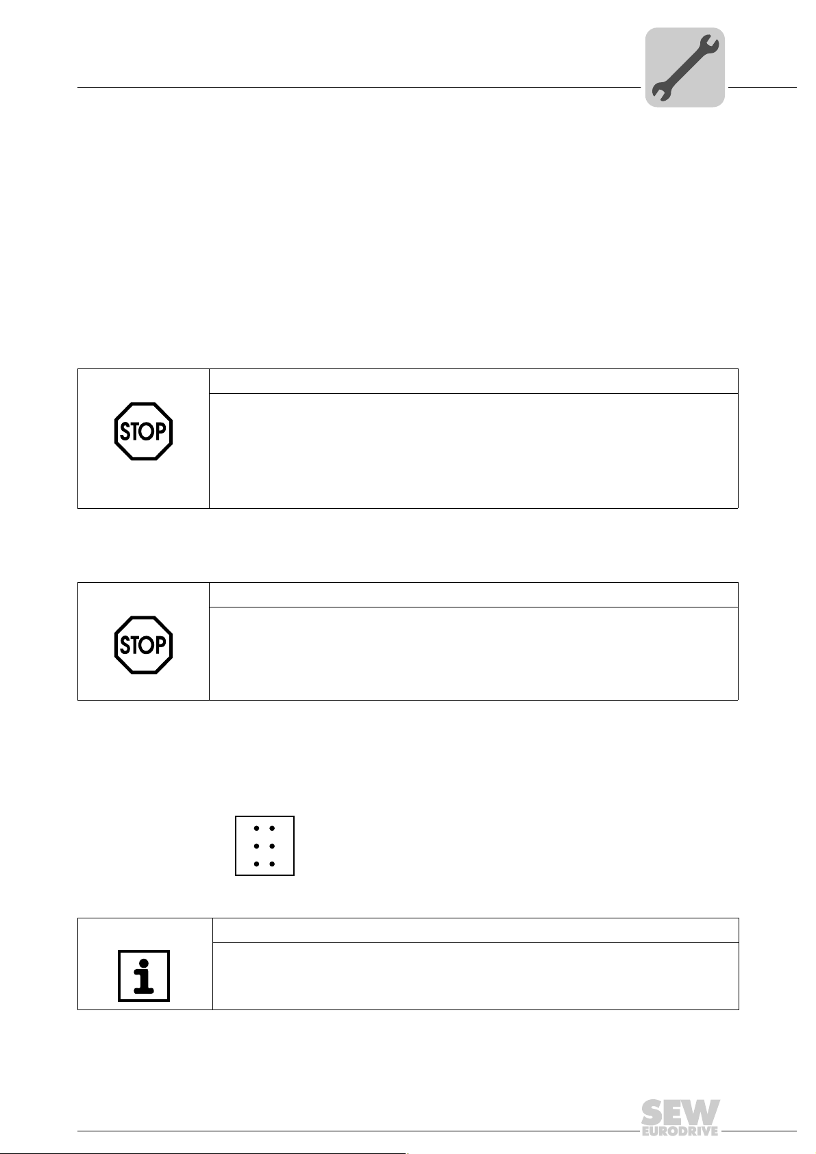
Setting the station address
The PROFIBUS station address is set using DIP switches 20 ... 26 on the MOVI-PLC
advanced DHF41B controller.
The MOVI-PLC
DHF41B
®
advanced DHF41B controller supports the address range 0...125.
The default setting for the station address is 4:
0
→ Significance: 1 × 0 = 0
2
1
2
→ Significance: 2 × 0 = 0
0
2
1
2
2
2
ON
3
2
4
2
5
2
6
2
7
2
63210AXX
2
2
→ Significance: 4 × 1 = 4
3
→ Significance: 8 × 0 = 0
2
4
2
→ Significance: 16 × 0 = 0
5
2
→ Significance: 32 × 0 = 0
6
→ Significance: 64 × 0 = 0
2
Any change made to the PROFIBUS station address during ongoing operation does not
take effect immediately. You have to switch the compact controller or the inverter in
which the MOVI-PLC
®
advanced DHF41B controller is installed on and off again for the
changes to take effect (power + 24 V off/on).
4.4.3 Connecting DeviceNet (connector X30D)
®
The connection to the DeviceNet fieldbus system is in preparation.
Pin assignment The assignment of connecting terminals is described in the DeviceNet specification
(Volume I, Appendix A).
DFD11B
DHF41B
1
2
3
4
5
X30D
61612AXX
The DHF41B option card is opto-decoupled on the driver side in accordance with the
DeviceNet specification (Volume I, Chapter 9). This means the CAN bus driver must be
powered with 24 V voltage via the bus cable. The cable to be used is also described in
the DeviceNet specification (Volume I, Appendix B). The connection must be made according to the color code specified in the following table.
Pin no. Signal Meaning Color coding
1V– 0 V 24 BK
2CAN_L CAN_L BU
3 DRAIN DRAIN blank
4CAN_H CAN_H WH
5V+ 24 V RD
Manual – MOVI-PLC® advanced DHE41B/DHF41B/DHR41B Controller
27

4
Mounting/Installation Instructions
Installing the MOVI-PLC® advanced DHF41B controller
Setting the station address
Setting the baud rate
The DeviceNet station address is set using DIP switches 20 ... 25 on the MOVI-PLC
advanced DHF41B controller.
The MOVI-PLC
DHF41B
®
advanced DHF41B controller supports the address range 0..0.63.
The default setting for the station address is 4:
0
→ Significance: 1 × 0 = 0
2
1
2
→ Significance: 2 × 0 = 0
0
2
1
2
2
2
ON
3
2
4
2
5
2
6
2
7
2
63210AXX
2
→ Significance: 4 × 1 = 4
2
3
2
→ Significance: 8 × 0 = 0
4
2
→ Significance: 16 × 0 = 0
5
→ Significance: 32 × 0 = 0
2
Any change made to the DeviceNet station address during ongoing operation does not
take effect immediately. You have to switch the compact controller or the inverter in
®
which the MOVI-PLC
advanced DHF41B controller is installed on and off again for the
changes to take effect (power + 24 V off/on).
6
The baud rate is set with DIP switches 2
DIP switches
6
2
0 0 125 kbaud
1 0 250 kbaud
0 1 500 kbaud
11Invalid
and 27.
7
2
Baud rate
®
4.4.4 Connecting SafetyBus (connector X38)
The connection to the SafetyBus bus system is in preparation.
28
Manual – MOVI-PLC® advanced DHE41B/DHF41B/DHR41B Controller

Mounting/Installation Instructions
Installing the MOVI-PLC® advanced DHF41B controller
4.4.5 Operating displays of MOVI-PLC® advanced DHF41B
NOTE
The LEDs identical with DHE41B are described in section "Operating displays of the
MOVI-PLC
LEDs 11, 12 LEDs 11 and 12 are reserved.
®
advanced DHE41B controller.
4
LED L13 (BUS-OFF)
The LED L13 (BUS-OFF) displays the physical status of the bus node.
Status of the
LED L13
Off NO ERROR The number of bus errors is in the normal range (error
Flashing red
(125 ms
cycle)
Flashing red
(1 s cycle)
Red light BUS ERROR • BusOff state
Yellow light POWER OFF External voltage supply has been turned off or is not con-
Status Meaning
active status).
The unit is performing a DUP-MAC check and cannot
send any messages because no other stations are con-
BUS WARNING
nected to the bus (error passive state)
The number of physical bus errors is too high. No more
error telegrams are actively written to the bus (error passive state).
• The number of physical bus errors has increased
despite a switch to the error-passive state. Access to
the bus is switched off.
nected.
LED L14 (BIO) The LED L14 (Bit-strobe I/O) monitors the bit-strobe I/O connection.
Status of the
LED L14
Flashing
green
(125 ms
cycle)
Off Not switched on / off-line but
Flashing
green
(1 s cycle)
Lights up
green
Flashing red
(1 s cycle)
Red light Critical fault or critical link
Status Meaning
DUP-MAC check Unit is performing DUP-MAC check
not DUP-MAC check
Online and in operational
mode
Online, operational mode
and connected
Minor fault or connection timeout
failure
• Unit is off-line
• Unit is switched off
• Unit is on-line
• DUP MAC check performed successfully
• A BIO connection is being established with a master
(configuring state)
• Missing, incorrect or incomplete configuration
•Online
• A BIO connection has been established (established
state)
• Invalid number of process data is set via DIP switches
• A correctable fault has occurred
• Bit-strobe I/O connection is in timeout state
• An error that cannot be corrected has occurred
•BusOff
• DUP-MAC check has detected an error
Manual – MOVI-PLC® advanced DHE41B/DHF41B/DHR41B Controller
29

4
Mounting/Installation Instructions
Installing the MOVI-PLC® advanced DHF41B controller
LED L15 (PIO) The LED L15 (Polled I/O) monitors the polled I/O connection.
LED L16 (Mod/Net)
Status of the
LED L15
Flashing
green
(125 ms
cycle)
Off Not switched on / off-line but
Flashing
green
(1 s cycle)
Lights up
green
Flashing red
(1 s cycle)
Red light Critical fault or critical link
Status Meaning
DUP-MAC check Unit is performing DUP-MAC check
not DUP-MAC check
Online and in operational
mode
Online, operational mode
and connected
Minor fault or connection timeout
failure
• Unit is off-line
• Unit is switched off
• Unit is on-line
• DUP MAC check performed successfully
• A polled I/O connection is being established with a
master (configuring state)
• Missing, incorrect or incomplete configuration
•Online
• A polled I/O connection has been established (estab-
lished state)
• Invalid baud rate set via DIP switches
• A correctable fault has occurred
• Polled I/O connection is in timeout status
• An error that cannot be corrected has occurred
•BusOff
• DUP-MAC check has detected an error
The function of the LED L16 (Mod/Net = Module/Network Status) described in the following table is specified in the DeviceNet specification.
Status of the
LED L16
Off Not switched on / OffLine • Unit is off-line
Flashing
green
(1 s cycle)
Lights up
green
Flashing red
(1 s cycle)
Red light Critical fault or critical link
Status Meaning
• Unit performs DUP MAC check
• Unit is switched off
Online and in operational
mode
Online, operational mode
and connected
Minor fault or connection timeout
failure
• The unit is on-line and no connection has been established
• DUP MAC check performed successfully
• A connection has not yet been established with a master
• Missing, incorrect or incomplete configuration
•Online
• Connection to a master has been established
• Connection is active (established state)
• A correctable fault has occurred
• Polled I/O or/and bit-strobe I/O connection are in timeout status
• DUP-MAC check has detected an error
• A correctable fault has occurred
•BusOff
• DUP-MAC check has detected an error
30
Manual – MOVI-PLC® advanced DHE41B/DHF41B/DHR41B Controller

Mounting/Installation Instructions
Installing the MOVI-PLC® advanced DHF41B controller
4
LED L17 (Fault Profibus)
LED L18 (Run Profibus)
The LED L17 (Fault Profibus) indicates that communication via the PROFIBUS inter-
face is working properly.
Status of the
LED L17
Off • The MOVI-PLC
Red • Connection to the DP master has failed.
Flashing red
(1 Hz)
Diagnostics Troubleshooting
®
troller exchanges data with the PROFIBUS-DP master (data exchange status).
• The MOVI-PLC
troller does not recognize the PROFIBUS
baud rate.
• Bus interruption has occurred.
• PROFIBUS-DP master not in operation.
• The MOVI-PLC
troller recognizes the baud rate, but the DP
master does not communicate with
MOVI-PLC
• The MOVI-PLC
troller was either not configured in the DP
master or it was configured incorrectly.
advanced DHF41B con-
®
advanced DHF41B con-
®
advanced DHF41B con-
®
advanced DHF41B.
®
advanced DHF41B con-
-
• Check the PROFIBUS connection on
the unit.
• Check project planning of the
PROFIBUS DP master.
• Check all the cables in the PROFIBUS network.
• Check and correct the PROFIBUS
station address set in the
MOVI-PLC
troller and in the configuration software of the DP master.
• Check and correct the configuration
of the DP master.
• Use the GSD file SEW_6007.GSD
with the designation MOVI-PLC for
configuration.
®
advanced DHF41B con-
LED L18 (Run Profibus) indicates the proper functioning of the PROFIBUS electronics
(hardware).
Status of the
LED L18
Green • PROFIBUS hardware OK. -
Flashing
green
(1 Hz)
Diagnostics Troubleshooting
• The PROFIBUS station address set on
the DIP switches is more than 125. If the
PROFIBUS station address is set to a
value higher than 125, MOVI-PLC
advanced DHF41B will use PROFIBUS
station address 4.
®
1. Check and correct the PROFIBUS
station address on the DIP switches.
2. Switch on all drive inverters again.
The modified PROFIBUS address
will only take effect after a restart.
Manual – MOVI-PLC® advanced DHE41B/DHF41B/DHR41B Controller
31

4
Mounting/Installation Instructions
Installing the MOVI-PLC® advanced DHR41B controller
4.5 Installing the MOVI-PLC® advanced DHR41B controller
4.5.1 Function description of the terminals, DIP switches and LEDs
NOTE
The connections identical with DHE41B and DHF41B are described in the sections "Installation of the MOVI-PLC
®
advanced DHE41B/DHF41B controller".
Front view
MOVI-PLC
®
advanced DHR41B
controller
DHR41B
L14
X30-1
L13
X30-2
0
2
1
2
ON
1
L12
2
3
L11
X38
2
1
L10
4
3
L9
6
5
X31
8107
L8
9
L7
2
1
L6
4
3
X34
6
5
T1
L5
342
L4
L3
S1
XM
L2
L1
X35
1
X36
X37
1
1
2
2
X32X33
3
3
1
1
2
2
3
3
63362AXX
LED
Designation
DIP switches
Term inal
LED LED 1
LED 2
LED 3
LED 4
LED 5
LED 6
LED 7
LED 8
LED 9
LED 10
LED 11
LED 12
LED 13
LED 14
Connector X30-1:
X30-1
Ethernet 3
(RJ45 socket)
Connector X30-2:
X30-2
Ethernet 4
(RJ45 socket)
0
DIP switches 2
, 2
1
Connector X38:
SafetyBus
(plug-in terminals)
Terminal X31:
Binary inputs and outputs
(plug-in terminals, color:
BK))
0
2
1
2
X38:1
X38:2
X38:3
X31:1
X31:2
X31:3
X31:4
X31:5
X31:6
X31:7
X31:8
X31:9
X31:10
Terminal X34:
RS485 interfaces COM1,
COM2
(plug-in terminals, color:
BK)
X34:1
X34:2
X34:3
X34:4
X34:5
X34:6
Connector X35:
USB connection (in preparation)
X35:1
X35:2
X35:3
X35:4
CAN 1 status
CAN 2 status
IEC progr. status
PLC status
User LED
DIO6/7
DIO4/5
DIO2/3
DIO0/1
24V / I/O OK
-
-
ON
OFF
ON
OFF
+24 V input
REF24V
DIO 0
DIO 1
DIO 2
DIO 3
DIO 4
DIO 5
DIO 6
DIO 7
RS+
RS+ insulated
RS–
RS– insulated
DGND
GND insulated
USB+5 V
USB–
USB+
DGND
Function
Status of CAN 1 system bus
Status of CAN 2 system bus
Status of control program
Status of control firmware
Freely programmable
Status input or output DIO6/7
Status input or output DIO4/5
Status input or output DIO2/3
Status input or output DIO0/1
Status of voltage supply I/O
Reserved
Reserved
Bus status
Bus status
Standard Ethernet assignment
Default IP address (192.168.10.4)
Stored IP address / DHCP
EtherNet/IP / Modbus TCP/IP
PROFINET
Reserved
Reserved
Reserved
Voltage input DC+24 V
Reference potential for binary signals
Binary input or output
Binary input or output
Binary input or output
Binary input or output
Binary input or output
Binary input or output
Binary input or output
Binary input or output
Signal RS485+ (COM 1)
Signal RS485+ insulated (COM 2)
Signal RS485– (COM 1)
Signal RS485– insulated (COM 2)
Reference potential (COM 1)
Reference potential (COM 2)
DC 5 V power supply
Signal USB–
Signal USB+
Reference potential
32
Manual – MOVI-PLC® advanced DHE41B/DHF41B/DHR41B Controller

Mounting/Installation Instructions
Installing the MOVI-PLC® advanced DHR41B controller
4
Front view
MOVI-PLC
advanced DHR41B
controller
®
LED
Designation
Connector X36:
Connection Ethernet 1
System bus (RJ45
socket)
Connector X37:
Connection Ethernet 2
(RJ45 socket)
Terminal X32:
System bus CAN 2
(electrically isolated)
(plug-in terminals, color:
YE/BK)
Terminal X33:
System bus CAN 1
(plug-in terminals, color:
YE/BK)
DIP switch S1 S1
Reset button T1 T1 Reset
DIP switches
Term inal
X36
X37
X32:1
X32:2
X32:3
X33:1
X33:2
X33:3
REF_CAN 2
CAN 2H
CAN 2L
DGND
CAN 1H
CAN 1L
To p
Bottom
Function
Standard Ethernet assignment
Reference potential for system bus CAN 2
System bus CAN 2 high
System bus CAN 2 low
Reference potential for system bus CAN 1
System bus CAN 1 high
System bus CAN 1 low
Default IP address
Ethernet 2 connection
Manual – MOVI-PLC® advanced DHE41B/DHF41B/DHR41B Controller
33

4
4.5.2 Pin assignment
Mounting/Installation Instructions
Installing the MOVI-PLC® advanced DHR41B controller
Use prefabricated, shielded RJ45 plug connectors compliant with IEC 11801, edition
2.0, category 5.
[1]
[2]
[3]
[6]
AB
Figure 8: Pin assignment of an RJ45 plug connector
A = Front view
B = View from back
[1] Pin 1 TX+ Transmit Plus
[2] Pin 2 TX– Transmit Minus
[3] Pin 3 RX+ Receive Plus
[6] Pin 6 RX– Receive Minus
6
3
2
1
54174AXX
MOVIDRIVE
®
B / MOVITRAC® B / Ethernet connection
To connect DHR41B to the Ethernet, connect the Ethernet interface X30-1 or X30-2
(RJ45 plug connector) to the other network stations using a category 5, class D twistedpair cable in accordance with IEC 11801 edition 2.0. The integrated switch provides support for realizing a line topology and offers auto crossing functions.
NOTES
• According to IEC 802.3, the maximum cable length for 10/100 MBaud Ethernet
(10BaseT/100BaseT), e.g. between two network stations, is 100 m.
• We recommend that you do not directly connect end devices to the DHR41B option
in order to minimize the load on the end devices caused by undesired multicast data
traffic. Connect non-SEW devices via a network component that supports the IGMP
snooping functionality (e.g. managed switch).
34
Manual – MOVI-PLC® advanced DHE41B/DHF41B/DHR41B Controller

Installing the MOVI-PLC® advanced DHR41B controller
4.5.3 Shielding and routing bus cables
Only use shielded cables and connection elements that also meet the requirements of
category 5, class 2 in compliance with IEC 11801 edition 2.0.
Correct shielding of the bus cable attenuates electrical interference that may occur in
industrial environments. The following measures ensure the best possible shielding:
• Manually tighten the mounting screws on the connectors, modules, and equipotential
bonding conductors.
• Use only connectors with a metal housing or a metallized housing.
• Connect the shielding in the connector over a wide surface area.
• Apply the shielding of the bus line on both ends.
• Route signal and bus cables in separate cable ducts. Do not route them parallel to
power cables (motor leads).
• Use metallic, grounded cable racks in industrial environments.
• Route the signal cable and the corresponding equipotential bonding close to each
other using the shortest possible route.
• Avoid using plug connectors to extend bus cables.
• Route the bus cables closely along existing grounding surfaces.
Mounting/Installation Instructions
4
STOP!
In case of fluctuations in the ground potential, a compensating current may flow via the
bilaterally connected shield that is also connected to the protective earth (PE). Make
sure you supply adequate equipotential bonding in accordance with relevant VDE
regulations in such a case.
4.5.4 Setting the DIP switches 2
NOTE
The setting of the "20" DIP switch is only adopted with a power-on reset (switching on
and off line voltage and DC 24 V backup voltage).
DIP switch 2
0
If the "20" switch is set to "1" (= ON), the following default IP address parameters are set
when activating the DC 24 V backup voltage:
• IP address: 192.168.10.4
• Subnetwork mask: 255.255.255.0
• Default gateway: 1.0.0.0 for EtherNet/IP (192.168.10.4 for PROFINET)
• P785 DHCP / Startup Configuration: Saved IP parameters (DHCP is deactivated)
0
and 2
1
DIP switch 2
Manual – MOVI-PLC® advanced DHE41B/DHF41B/DHR41B Controller
1
DIP switch "21" is used to set the fieldbus protocol that is currently used.
1
•2
= "1" (= ON) the EtherNet/IP / Modbus TCP/IP fieldbus protocol is active
1
•2
= "0" (= OFF) the PROFINET fieldbus protocol is active.
35

4
Mounting/Installation Instructions
Installing the MOVI-PLC® advanced DHR41B controller
4.5.5 TCP / IP addressing and subnetworks
Introduction The settings for the address of the IP protocol are made using the following parameters:
• MAC address
• IP address
• Subnetwork mask
• Standard gateway
The addressing mechanisms and subdivision of the IP networks into subnetworks are
explained in this chapter to help you set the parameters correctly.
MAC address The MAC address (Media Access Controller) is the basis for all address settings. The
MAC address of an Ethernet device is a worldwide unique 6-byte value (48 bits). SEW
Ethernet devices have the MAC address 00-0F-69-xx-xx-xx. The MAC address is difficult to handle for larger networks. This is why freely assignable IP addresses are used.
IP address The IP address is a 32 bit value that uniquely identifies a station in the network. An IP
address is represented by four decimal numbers separated by decimal points.
Example: 192.168.10.4
Each decimal number stands for one byte (= 8 bits) of the address and can also be represented using binary code (see following table).
Byte 1 Byte 2 Byte 3 Byte 4
11000000 . 10101000 . 00001010 . 00000100
The IP address comprises a network address and a station address (see following
table).
Network address Station address
192.168.10 4
The part of the IP address that denotes the network and the part that identifies the station is determined by the network class and the subnetwork mask.
Station addresses cannot consist of only zeros or ones (binary) because they represent
the network itself or a broadcast address.
Network classes The first byte of the IP address determines the network class and as such represents
the division into network addresses and station addresses.
Value ra nge
Byte 1
0 ... 127 A 10.1.22.3 10 = Network address
128 ... 191 B 172.16.52.4 172.16 = Network address
192 ... 223 C 192.168.10.4 192.168.10 = Network address
Network class
Complete network address
(Example)
Meaning
1.22.3 = Station address
52.4 = Station address
4 = Station address
36
This rough division is not sufficient for a number of networks. They also use an explicit,
adjustable subnet mask.
Manual – MOVI-PLC® advanced DHE41B/DHF41B/DHR41B Controller

Mounting/Installation Instructions
Installing the MOVI-PLC® advanced DHR41B controller
Subnet mask A subnet mask is used to divide the network classes into even finer sections. The subnet
mask is represented by four decimal numbers separated by decimal points, in the same
way as the IP address.
Example: 255.255.255.128
Each decimal number stands for one byte (= 8 bits) of the subnetwork mask and can
also be represented using binary code (see following table).
Byte 1 Byte 2 Byte 3 Byte 4
11111111 . 11111111 . 11111111 . 10 000000
If you compare the IP addresses with the subnet masks, you see that in the binary representation of the subnet mask all ones determine the network address and all the zeros
determine the station address (see following table).
Byte 1 Byte 2 Byte 3 Byte 4
IP address
Subnetwork mask
Decimal 192 . 168. . 10 . 129
Binary 11000000 . 10101000 . 00001010 . 10000001
Decimal 255 . 255 . 255 . 128
Binary 11111111 . 11111111 . 11111111 . 10000000
4
The class C network with the address 192.168.10. is further subdivided into
255.255.255.128 using the subnetwork mask. Two networks are created with the ad-
dress 192.168.10.0 and 192.168.10.128.
The following station addresses are permitted in the two networks:
• 192.168.10.1 ... 192.168.10.126
• 192.168.10.129 ... 192.168.10.254
The network stations use a logical AND operation for the IP address and the subnetwork
mask to determine whether there is a communication partner in the same network or in
a different network. If the communication partner is in a different network, the standard
gateway is addressed for passing on the data.
Standard gateway The standard gateway is also addressed via a 32-bit address. The 32-bit address is rep-
resented by four decimal numbers separated by decimal points.
Example: 192.168.10.1
The standard gateway establishes a connection to other networks. In this way, a network station that wants to address another station can use a logical AND operation with
the IP address and the subnetwork mask to decide whether the desired station is located
in the same network. If this is not the case, the station addresses the standard gateway
(router), which must be part of the actual network. The standard gateway then takes on
the job of transmitting the data packages.
DHCP (Dynamic
Host Configuration Protocol)
Instead of setting the three parameters IP address, subnetwork mask and standard
gateway manually, they can be assigned in an automated manner by a DHCP server in
the Ethernet network.
This means the IP address is assigned from a table, which contains the allocation of
MAC address to IP address.
Parameter P785 indicates whether the DHR41B option expects the IP parameters to be
assigned manually or via DHCP.
Manual – MOVI-PLC® advanced DHE41B/DHF41B/DHR41B Controller
37

4
Mounting/Installation Instructions
Installing the MOVI-PLC® advanced DHR41B controller
4.5.6 Operating displays of the MOVI-PLC® advanced DHR41B controller in PROFINET mode
NOTE
The LEDs identical with DHE41B (L1 – L10) are described in section "Operating displays of the MOVI-PLC
There are 4 LEDs (L11, L12, L13, L14) on the DHR41B option card that display the current status of the DHR41B option, the PROFINET system and the safety options.
FS LED LED L12 (FAILSAFE-STATUS) indicates the failsafe status on PROFINET.
®
advanced DHE41B controller".
LED L13 (BUS-FAULT)
Status of
the "FS"
LED
Green • The safety option is currently perform-
Red • Fault status in the safety part.
Off • The safety option is currently in the
Flashing
red / green
Cause of error Troubleshooting
ing a cyclical data exchange with the
F-host (data exchange).
• Standard operating state.
• No 24 V_LS supply voltage present.
initialization phase.
A fault occurred in the safety part; cause
of the fault already remedied acknowledgement required.
–
• Read diagnostic in F-Host.
• Eliminate the cause of the fault and
acknowledge in the F-Host.
• Check voltage supply.
• Check configuration of the bus master.
Acknowledge fault in the F-Host (reintegration).
The LED L13 (BUS FAULT) displays the status of the PROFINET.
Status of the
LED L13
Off • PROFINET IO device is currently
Flashing green
Flashing
green/red
Red • Connection to the PROFINET IO
Yellow
Flashing yellow
Cause of error Troubleshooting
exchanging data with the PROFINET
IO controller (Data Exchange).
• The flashing function in the PROFINET IO controller project planning is
activated to visually localize the stations.
controller has failed.
• PROFINET IO device does not
detect a link
• Bus interruption
• PROFINET IO controller is not in
operation
• The STEP 7 hardware configuration
contains a module that is not permitted.
-
-
• Check the PROFINET connection of
the DHR41B option
• Check the PROFINET IO controller
• Check the cabling of your PROFINET
network
• Switch the STEP 7 hardware configuration to ONLINE and analyze the status of the components of the slots in
the PROFINET IO device.
38
Manual – MOVI-PLC® advanced DHE41B/DHF41B/DHR41B Controller

Mounting/Installation Instructions
Installing the MOVI-PLC® advanced DHR41B controller
LED L14 (RUN) LED L14 (RUN) indicates that the bus electronics are operating correctly.
4
LED Link / Activity
Status of the
LED L14
Green • DHR41B hardware OK.
Off • DHR41B is not ready for opera-
Red • Error in the DHR41B hardware
Flashing
green
Flashing
yellow
Yellow • Switch the unit on again. Consult SEW Ser-
Cause of error Troubleshooting
• Proper operation
tion.
• Hardware of the DHR41B does
not boot up.
–
• Switch the unit on again. Consult SEW Service if the error occurs again.
• Switch the unit on again. Set default IP
addressparameter via DIP switch "S1". Consult SEW service if the error occurs again.
vice if the error occurs again.
The two LEDs Link (green) and Activity (yellow), integrated in the RJ45 plug connectors (X30-1, X30-2), display the status of the Ethernet connection.
LED "Link"
X30-1
LED "Activity"
X30-2
LED / Status Meaning
Link / Green There is an Ethernet connection.
Link / Off There is no Ethernet connection.
Activity / Yellow
Data is currently being exchanged via Ethernet.
63365AXX
Manual – MOVI-PLC® advanced DHE41B/DHF41B/DHR41B Controller
39

4
4.5.7 Setting the IP address parameters via DCP
Initial startup For PROFINET IO, the IP address parameters are determined via the "DCP" protocol
Mounting/Installation Instructions
Installing the MOVI-PLC® advanced DHR41B controller
(Discovery and Configuration Protocol). DCP operates with device names (Device
Name). The device name uniquely identifies a PROFINET IO station in the network. It
is identified with the PROFINET IO controller for the project planning of the station and
also set using the project planning software on the PROFINET IO device. With the aid
of the device name, the controller identifies the device during startup and transfers the
corresponding IP address parameters. Settings directly on the slave are no longer required.
Resetting the IP
address parameters
If you do not know the IP address parameters and cannot access the inverter using the
serial interface or the DBG60B keypad, you can reset the IP address parameters to the
default values using the DIP switch "2
This action resets the DHR41B option to the following default values:
• IP address: 192.168.10.4
• Subnetwork mask: 255.255.255.0
• Default gateway: 1.0.0.0
• PROFINET device name: PNETDeviceName_MACID
Proceed as follows to reset the IP address parameters to the default values:
• Switch off the 24 V DC supply voltage and the mains voltage.
• Set the DIP switch "2
• Switch the DC 24 V supply voltage and the line voltage back on.
• Wait until the DHR41B option has booted up. The "RUN" LED is green when the option is ready.
You can now access the inverter via the IP address 192.168.10.4. Proceed as follows
to set new IP address parameters:
• Start MOVITOOLS
• Select the address parameters you want.
• Set the DIP switch "2
• The new address parameters are adopted after the device is switched off and
switched on again.
0
" on the DHR41B option to "1".
®
MotionStudio.
0
" on the DHR41B option to "0".
0
".
40
Manual – MOVI-PLC® advanced DHE41B/DHF41B/DHR41B Controller

Mounting/Installation Instructions
Installing the MOVI-PLC® advanced DHR41B controller
4.5.8 Operating displays of the MOVI-PLC® advanced DHR41B controller in EtherNet/IP mode
The LEDs L13 and L14 of the DHR41B indicate the current condition of the DHR41B
option and the EtherNet/IP system.
4
LED L13 (NETWORK STATUS)
LED L14 (MODULE STATUS)
LED L13 (NETWORK STATUS) indicates the status of the EtherNet/IP system.
Status of the LED
L13
Off The DHR41B option does not yet have any IP parameters.
Flashing green/red The DHR41B option card performs an LED test.
Flashing green There is no controlling IO connection.
Green There is a controlling EtherNet/IP IO connection.
Red A conflict while assigning the IP address was detected. Another station in the net-
Flashing red The previously established controlling IO connection is in timeout status. The sta-
Meaning
work uses the same IP address.
tus is reset by restarting communication.
LED L14 (MODULE STATUS) indicates that the bus electronics are operating correctly.
Status of the LED L14 Meaning
Off The DHR41B option card is not supplied with voltage or is defective
Flashing green • If the NETWORK STATUS LED is off at the same time, the TCP/IP stack of
Flashing green/red The DHR41B option card performs an LED test.
Green Indicates the standard operating state of the DHR41B option card
Red The DHR41B option card is in fault state.
Flashing red A conflict while assigning the IP address was detected. Another station in the net-
the DHR41B option card will be started. If this status continues and DHCP is
activated, the DHR41B option card waits for data from the DHCP server.
• If the NETWORK STATUS LED is flashing green at the same time, the application of the DHR41B option card is started.
work uses the same IP address.
Manual – MOVI-PLC® advanced DHE41B/DHF41B/DHR41B Controller
41

4
Mounting/Installation Instructions
Installing the MOVI-PLC® advanced DHR41B controller
LED Link / Activity
The two LEDs Link (green) and Activity (yellow), integrated in the RJ45 plug connectors (X30-1, X30-2), display the status of the Ethernet connection.
LED "Link"
LED "Activity"
LED / Status Meaning
Link / Green There is an Ethernet connection.
Activity / Yellow
Link / Off There is no Ethernet connection.
X30-1
X30-2
63365AXX
Data is currently being exchanged via Ethernet.
42
Manual – MOVI-PLC® advanced DHE41B/DHF41B/DHR41B Controller

Mounting/Installation Instructions
Installing the MOVI-PLC® advanced DHR41B controller
4.5.9 Setting the IP address parameters
Initial startup The "DHCP" protocol (Dynamic Host Configuration Protocol) is activated as the default
setting for the DHR41B option. This means that the DHR41B option card expects its IP
address parameters from a DHCP server.
NOTE
Rockwell Automation provides a DHCP server free-of-charge on their homepage. The
tool is known as "BOOTP Utility" and can be downloaded from the following website:
http://www.ab.com/networks/bootp.html.
Once the DHCP server has been configured and the settings have been made for the
subnetwork screen and the standard gateway, the DHR41B must be inserted in the assignment list of the DHCP server. In doing so, the MAC ID of the DHR41B option is allocated a valid IP address.
NOTE
The configured IP address parameters are permanently adopted into the parameter
set if DHCP is deactivated after the IP address has been assigned.
4
Changing the IP
address parameters after successful initial
startup
If the DHR41B was started using a valid IP address, you can also access the IP address
parameters via the Ethernet interface.
The following options are available for changing the IP address parameters via Ethernet:
• With the MOVITOOLS
• With the EtherNet/IP TCP/IP interface object
You can also use the DBG60B keypad to change the IP address parameters. To do so,
connect the DBG60B keypad to the serial interface (X24) of the UOH21B compact controller.
If the IP address parameters are assigned to the option DHR41B via a DHCP server,
you can only change the parameters by adjusting the settings of the DHCP server.
The options listed above for changing the IP address parameters only come into effect
once the supply voltages (mains and DC 24 V) have been switched off and back on
again.
®
MotionStudio software via Ethernet
Manual – MOVI-PLC® advanced DHE41B/DHF41B/DHR41B Controller
43

4
Mounting/Installation Instructions
Installing the MOVI-PLC® advanced DHR41B controller
Deactivating / activating the DHCP
Resetting the IP
address parameters
The type of IP address allocation is determined by the setting of the attribute Configuration Control of the EtherNet/IP TCP/IP interface object. The value is displayed or modi-
fied in the parameter P785 DHCP/Startup Configuration.
• Setting "Saved IP parameters"
The saved IP address parameters are used.
• Setting "DHCP"
The IP address parameters are requested by a DHCP server.
If you use the DHCP server from Rockwell Automation, you can activate or deactivate the DHCP via a button. In this case, an EtherNet/IP telegram is sent to the
TCP/IP interface object of the station that is being addressed.
If you do not know the IP address parameters and there is no serial interface or DGB60B
keypad for reading the IP address, you can reset the IP address parameters to the default values using the DIP switch "2
This action resets the DHR41B option to the following default values:
• IP address: 192.168.10.4
• Subnetwork mask: 255.255.255.0
• Default gateway: 1.0.0.0
• P785 DHCP/Startup Configuration: Saved IP parameters (DHCP is deactivated)
0
".
Proceed as follows to reset the IP address parameters to the default values:
• Switch off the 24 V DC supply voltage and the mains voltage.
• Set the DIP switch "2
• Switch the DC 24 V supply voltage and the line voltage back on.
• Wait until the DHR41B option has booted up. The "MODULE STATUS" LED is green
when the option is ready.
• Set the DIP switch "2
• The following options are available to assign the new IP address:
– With the MOVITOOLS
– With the EtherNet/IP TCP/IP interface object
0
" on the DHR41B option to "1".
0
" on the DHR41B option to "0".
®
MotionStudio software via Ethernet
NOTE
• DHCP remains deactivated when you reset the DIP switch "20" to "0". You can reactivate DHCP via the EtherNet/IP TCP/IP interface object, parameter P785 or the
DHCP server by Rockwell Automation.
• DHCP remains active when resetting the values to the default setting (P802 Factory
setting).
44
Manual – MOVI-PLC® advanced DHE41B/DHF41B/DHR41B Controller

Mounting/Installation Instructions
Installing the MOVI-PLC® advanced DHR41B controller
4.5.10 The integrated Ethernet switch
You can use the integrated Ethernet switch to achieve line topologies known from the
fieldbus technology. Other bus topologies, such as star or tree, are also possible. Ring
topologies are not supported.
NOTE
The number of industrial Ethernet switches connected to the line affects the telegram
runtime. If a telegram passes through the units, the telegram runtime is delayed by the
Store & Forward function of the Ethernet switch:
• For a telegram length of 64 Byte by approximately 10 µs (at 100 Mbit/s)
• For a telegram length of 1500 Byte by approximately 130 µs (at 100/Mbit/s)
This means that the more units a telegram has to pass through, the higher the telegram
runtime is.
Autocrossing: The two ports leading out of the Ethernet switch have autocrossing functionality. This
means you can use patch or cross-over cables to connect the next Ethernet node.
4
Autonegotiation The baud rate and the duplex mode is negotiated by both Ethernet nodes when estab-
lishing the connection. The two Ethernet ports of the EtherNet/IP interface support autonegotiation functionality and operate at a baud rate of 100 Mbit or 10 Mbit in full duplex
or half duplex mode.
Notes on multicast handling
• The integrated Ethernet switch does not provide a filter function for Ethernet multicast telegrams. Multicast telegrams that are usually sent from the adapters
(DHR41B) to the scanners (PLC) are passed on to all switch ports.
• IGMP snooping (managed switch) is not supported.
• SEW-EURODRIVE recommends to connect DHR41B only with network components
that support IGMP Snooping (e. g. managed switch) or in which protective measures
against excessive multicast load are integrated (e. g. units from SEW-EURODRIVE).
When using units that do not possess this function, the high load on the network can
cause faults.
Manual – MOVI-PLC® advanced DHE41B/DHF41B/DHR41B Controller
45

4
Mounting/Installation Instructions
Installing the DH.41B option in MOVIDRIVE® MDX61B
4.6 Installing the DH.41B option in MOVIDRIVE® MDX61B
NOTE
The MOVI-PLC® advanced DH.41B controller is installed according to chapter "Mounting options for the MOVI-PLC
vanced DH.41B controller is powered via MOVIDRIVE
supply is only required for the binary inputs and outputs (connector X31).
®
advanced DH.41B controller". The MOVI-PLC® ad-
®
MDX61B. A separate voltage
4.7 Installation of the DH.41B option in the MOVIAXIS® MDX61B master module
NOTE
The MOVI-PLC® advanced DH.41B controller is installed according to chapter "Mounting options for the MOVI-PLC
connect connector X33 (CAN1) or X32 (CAN2) of MOVI-PLC
connector X9 (MOVIAXIS
module) or with connector X12 (CAN2 bus of a MOVIAXIS
MOVIAXIS
®
master module also provides further connections as described below.
®
advanced DH.41B controller". To wire the system bus,
®
supply module signalizing bus or of a MOVIAXIS® axis
®
advanced DH.41B with
®
axis module). The
4.7.1 Function description of terminals X5a/X5b (MOVIAXIS® master module)
MOVIAXIS® master
module MXM
1
X5b
2
3
4
1
X5a
2
3
4
59233AXX
• The connectors X5a and X5b are connected in parallel. In this way, the voltage supply of the MOVIAXIS
Designation Termin al Function
X5b connector X5b:1
X5a connector X5a:1
®
master module can be provided from the right to X5b or from
X5b:2
X5b:3
X5b:4
X5a:2
X5a:3
X5a:4
DC 24 V
DGND
DC 24 V
BGND
DC 24 V
DGND
DC 24 V
BGND
Voltage supply for control electronics
E
Reference potential of control electronics
B
Brake voltage supply
Reference potential for brake connection
Voltage supply for control electronics
E
Reference potential of control electronics
B
Brake voltage supply
Reference potential for brake connection
below to X5a. With connection to X5a, further modules can be connected via X5b
(e.g. supply module, axis module). The voltage supply of brake (X5a/b:3, 4) is conducted by the MOVIAXIS
• The MOVI-PLC
®
advanced DH.41B controller can be supplied by the MOVIAXIS
®
master module.
switched mode power supply module (MXS) or from an external voltage supply. For
this purpose, connect X5 between the individual devices.
• If the MOVI-PLC
MOVIAXIS
®
®
advanced DH.41B controller is supplied with DC 24 V by the
switched-mode power supply module, the function of the MOVI-PLC
advanced DH.41B controller is maintained after disconnection from the power supply. This is the case if the DC link voltage is maintained or an external DC 24 V supply
of the MOVIAXIS
®
switched-mode power supply unit is present.
®
®
46
Manual – MOVI-PLC® advanced DHE41B/DHF41B/DHR41B Controller

Mounting/Installation Instructions
Installation of the DH.41B option in the MOVIAXIS® MDX61B master module
Wiring diagram
External DC 24 V
-
MOVIAXIS®
master module MXM
DHE41B
2
1
4
3
6
5
X31
8107
9
2
1
4
3
X34
6
5
X35
T1
342
1
Version
X36
S1
X37
X5b
1
2
3
4
+
X16
MOVIAXIS®
switched-mode
power supply MXS
X5a
1
2
3
4
X5b
1
2
3
4
DC 24V
DGND
DC 24V
BGND
E
B
4
X32X33
X5a
1
2
3
4
DC 24 V for
brake power supply
DC 24 V supply
+-+-
for control electronics
1
1
2
2
3
3
1
1
2
2
3
3
L1 L2 L3 L5XM L6 L7 L8 L9L4 L1 0
60301AEN
Manual – MOVI-PLC® advanced DHE41B/DHF41B/DHR41B Controller
47

4
4
Mounting/Installation Instructions
Installing the DH.41B option in MOVITRAC® B/compact controller
4.8 Installing the DH.41B option in MOVITRAC® B/compact controller
NOTE
The MOVI-PLC® advanced DH.41B controller is installed according to chapter "Mounting options for the MOVI-PLC
tion slot and the compact controller provide additional connections and operating displays for the MOVI-PLC
4.8.1 Function description of terminals and LEDs
®
advanced DH.41B controller". The MOVITRAC® B op-
®
advanced DH.41B controller as described below.
Front view
MOVITRAC
compact controller
Lateral view
Compact controller
X26
2345671
®
B/
H1
H2
X2
58905AXX
58906AXX
X26:1
X24:2
X24:3
X24:4
X26:5
X26:6
X26:7
LED
Term inal
H2
X24:4
X24:3
X24:2
X24:1
CAN1H
CAN1L
DGND
Reserved
Reserved
DGND
DC 24 V
Function
System fault
Reserved
DGND
RS–
RS+
5 V
Reference potential COM 1
Signal RS485–
Signal RS485+
Voltage output DC+5 V
System bus CAN 1 high
System bus CAN 1 low
Reference potential controller/CAN1
-
Reference potential controller/CAN1
Voltage supply of controller
Designation
LED H1
Connector X24:
RS485 COM 1
(RJ10 socket)
Designation Termin al Function
Connector X26:
CAN 1 and
voltage supply
(plug-in terminal)
4.8.2 Connection of RS485 interface COM 1 (connector X24)
The connectors X24 and X34:1/3/5 are connected in parallel. You can connect a
DOP11B operator terminal at X24. If X24 is unassigned, you can connect an operator
terminal or a gearmotor with integrated MOVIMOT
For more information, refer to section 4.4.5.
48
Manual – MOVI-PLC® advanced DHE41B/DHF41B/DHR41B Controller
®
frequency inveter to X34:1/3/5.

Mounting/Installation Instructions
Installing the DH.41B option in MOVITRAC® B/compact controller
4.8.3 Connection of system bus CAN 1/power supply (connector X26)
4
X26:1/2/3 and connector X33 are connected in parallel (see sec. 4.3.3). MOVI-PLC
advanced DH.41B in the compact controller is supplied with power via X26:6/7.
The MOVI-PLC
by MOVITRAC
X12:9/8. If the MOVI-PLC
MOVITRAC
®
advanced DH.41B controller can be supplied with the required voltage
®
B. For this purpose, connect X26:3 (6)/7 with X46:3 (6)/7 or with
®
B, the function of the MOVI-PLC® advanced DHE41B controller is main-
®
advanced DHE41B controller is supplied with DC 24 V by
tained after disconnection from the voltage supply. This requires an external DC 24 V
S2
®
B.
DHE41B
2
1
4
3
6
5
X31
8107
9
2
1
4
3
X34
6
5
X35
T1
342
1
X36
S1
X37
7
1
1
2
2
X32X33
3
3
1
1
2
2
3
3
L1 L2 L3 L5XM L6 L7 L8 L9L4 L1 0
120Ω
supply to X12:8 / 9 of MOVITRAC
MOVITRAC® B
S1
ON
OFF
X44
FSC11B
X46
X45
23456HL ⊥
1
®
H1
H2
X24
X26
1234567
DC 24V
X12
1
2
3
+
=
-
24V IO
GND
4
5
6
7
8
9
Figure 9: Installation of MOVI-PLC® advanced DHE41B in MOVITRAC® B
60302AXX
Manual – MOVI-PLC® advanced DHE41B/DHF41B/DHR41B Controller
49

4
Mounting/Installation Instructions
Installing the DH.41B option in MOVITRAC® B/compact controller
Compact controller
DHE41B
2
1
4
3
6
5
X31
8107
9
2
1
4
3
X34
6
5
X35
T1
342
1
X36
S1
X37
1
1
2
2
X32X33
3
3
1
1
2
2
3
3
L1 L2 L3 L5XM L6 L7 L8 L9L4 L10
120W
SEW drive
23456
1
SC11 System bus +, CAN high
SC12 System bus -, CAN low
GND, CAN GND
Figure 10: Installation of the MOVI-PLC® advanced DHE41B/UOH..B compact controller
4.8.4 MOVITRAC® B/compact controller option slot operating displays
LED H1 The LED H1 signals correct operation via connection X26.
Status of LED H1Diagnostics Troubleshooting
OFF • Correct operation of connection X26 -
X24
X26
H1
H2
7
DC +24 V
GND
60304AEN
LED H2 LED H2 is reserved.
50
Manual – MOVI-PLC® advanced DHE41B/DHF41B/DHR41B Controller

Mounting/Installation Instructions
Engineering interface of the MOVI-PLC® advanced DH.41B controller
4.9 Engineering interface of the MOVI-PLC® advanced DH.41B controller
4
The engineering access to the MOVI-PLC® advanced DH.41B controller is realized via
the Ethernet 2 interface (connector X37). Engineering access to the MOVI-PLC
advanced DHF41B controller is also possible via PROFIBUS (connector X30P) and to
the MOVI-PLC
®
advanced DHR41B controller via Ethernet (connector X30-1/2).
NOTE
For detailed information, refer to the "MOVI-PLC® advanced Fieldbus Interfaces
PROFIBUS DP-V1, Ethernet TCP/IP, EtherNet/IP, DeviceNet, Modbus TCP/IP"
manual.
4.10 Shielding and routing bus cables
Only use shielded cables and connection elements that also meet the requirements of
category 5, class 2 in compliance with IEC 11801 edition 2.0.
Correct shielding of the bus cable attenuates electrical interference that may occur in
industrial environments. The following measures ensure the best possible shielding:
• Manually tighten the mounting screws on the connectors, modules, and equipotential
bonding conductors.
• Use only connectors with a metal housing or a metallized housing.
• Connect the shielding in the connector over a wide surface area.
• Apply the shielding of the bus line on both ends.
• Route signal and bus cables in separate cable ducts. Do not route them parallel to
power cables (motor leads).
• Use metallic, grounded cable racks in industrial environments.
• Route the signal cable and the corresponding equipotential bonding close to each
other using the shortest possible route.
• Avoid using plug connectors to extend bus cables.
• Route the bus cables closely along existing grounding surfaces.
®
STOP!
In case of fluctuations in the earth potential, a compensating current may flow via the
bilaterally connected shield that is also connected to the protective earth (PE). Make
sure you supply adequate equipotential bonding according in accordance with relevant
VDE regulations in such a case.
Manual – MOVI-PLC® advanced DHE41B/DHF41B/DHR41B Controller
51

I
5
Project Planning and Startup
Configuration with the MOVITOOLS® MotionStudio PC software
00
5 Project Planning and Startup
This section provides information on project planning and startup
• For the MOVI-PLC
• For inverters controlled through the MOVI-PLC
• For the PROFIBUS DP master
5.1 Configuration with the MOVITOOLS® MotionStudio PC software
Project selection • Start the MOVITOOLS® MotionStudio software.
®
advanced DH.41B controller
®
advanced DH..1B controller
[1]
[2]
Figure 11: MOVITOOLS® MotionStudio start window
[1] Option [New project]
[2] Option [Open project]
• To create a new project, select the option [New project] [1].
• To open an existing project, select the option [Open project] [2].
58335AXX
52
Manual – MOVI-PLC® advanced DHE41B/DHF41B/DHR41B Controller

Project Planning and Startup
Configuration with the MOVITOOLS® MotionStudio PC software
I
5
00
Options for engineering access
Address settings
for a point-topoint connection
You have two options to establish engineering access to the MOVI-PLC® advanced
DH.41B controller via the Ethernet 2 interface (connector X37):
• For a point-to-point connection, connect the Ethernet 2 interface (X37) of the
MOVI-PLC
gineering PC. Use an interface of the engineering PC that is not used for connection
of the PC to the Intranet/Internet. In this way, you avoid reconfiguration of the interface.
• Integrate the MOVI-PLC
2 interface (X37). Edit the configuration file NetConfig.cfg in the "System" folder of
the SD memory card to make the necessary address settings. You have the following
options to access the NetConfig.cfg configuration file:
– Take the SD memory card out of the MOVI-PLC
and insert it into a memory card write/read device.
– First, establish a point-to-point connection to the MOVI-PLC
controller. Then access the NetConfig.cfg configuration file via an FTP client.
For older network interfaces, it can be necessary to use a cross cable for the pointto-point connection.
• Setting the default IP address:
– De-energize the MOVI-PLC
– Switch the DIP switch to the upper position.
– Re-energize the MOVI-PLC
192.168.10.4 and the net mask 255.255.255.0 are assigned automatically to the
Ethernet 2 interface of the MOVI-PLC
®
advanced DH.41B controller directly to the Ethernet interface of the en-
®
advanced DH.41B controller in a network via the Ethernet
®
advanced DH.41B controller
®
advanced DH.41B
®
advanced DH.41B controller.
®
advanced DH.41B controller. The IP address
®
advanced DH.41B controller.
• Setting other addresses:
By manually editing the section <Ethernet2...> in the NetConfig.cfg configuration file
in the "System" folder of the SD memory card, you can set other addresses.
Example:
<!-- Ethernet2 is engineering interface -->
<Ethernet2>
<IPAddress>192.168.10.4</IPAddress>
<Netmask>255.255.255.0>/Netmask>
<Gateway>192.168.10.1</Gateway>
<Nameserver>0.0.0.0</Nameserver>
<Hostname>MOVI-PLC_Eth2>/Hostname>
</Ethernet2>
Switch the DIP switch S1 to the lower position. This ensures that the addresses are
adopted during the next boot process of the MOVI-PLC
®
advanced DH.1B controller.
Manual – MOVI-PLC® advanced DHE41B/DHF41B/DHR41B Controller
53

5
I
Project Planning and Startup
Configuration with the MOVITOOLS® MotionStudio PC software
00
• Setting the IP address of the PC interface:
– Select the relevant PC interface under [Start] / [Settings] / [Network Connections].
In the context menu, select the properties window of the PC interface.
– Activate the option "Use this IP address" in the property window of the "Internet
protocol (TCP/IP)" entry.
– Enter the net mask which is set in the MOVI-PLC
(e. g. 255.255.255.0, if DIP switch S1 is in the upper position).
– Set the IP address depending on the net mask. The IP addresses of the MOVI-
®
PLC
advanced DH.41B controller (Ethernet 2) and the PC interface must be different except for the areas defined by the net mask. In the area defined by the net
mask, the IP addresses must be the same. The last byte of the IP address may
neither be 0 nor 255.
Example:
Net mask
decimal binary
255.255.255.0 11111111.11111111.11111111.00000000
In the example, the last 8 bits of the IP address of the MOVI-PLC
DH..41B controller and the PC interface must be different.
®
advanced DH.41B controller
®
advanced
Address settings for engineering access via a network
Proceed as follows to establish engineering access to the MOVI-PLC
DH.41B controller via an existing network:
• In the section <Ethernet2...> of the NetConfig.cfg configuration file in the "System"
folder of the SD memory card, enter the following according to the specifications of
your network administration:
– IP address
–Net mask
– Gateway address
• Switch the DIP switch S1 to the lower position. This ensures that the new address
settings are adopted during the next boot process of the MOVI-PLC
DH.41B controller.
®
advanced
®
advanced
54
Manual – MOVI-PLC® advanced DHE41B/DHF41B/DHR41B Controller

Project Planning and Startup
Configuration with the MOVITOOLS® MotionStudio PC software
I
5
00
Setting the engineering access in
MOVITOOLS
MotionStudio
®
• Open the menu item "Communication plugs" in MOVITOOLS
"Network" menu.
[1]
• Select the entry "Ethernet" [1] from the dropdown menu. Click on the <Edit> button
[2]. Confirm your selection with <OK>.
®
MotionStudio in the
63436AXX
[2]
• Right-click in the empty field "SMLP server IP addresses " and use menu item "Add
IP address" to add the IP address of the Ethernet 2 interface of the MOVI-PLC
advanced DH.41B controller (see following figure). Confirm your entry with <OK>.
®
Manual – MOVI-PLC® advanced DHE41B/DHF41B/DHR41B Controller
11950AXX
55

5
I
Project Planning and Startup
Configuration with the MOVITOOLS® MotionStudio PC software
00
• You can also enter the network address (the part of the IP address in which the bits
of the net mask are set) in the "Broadcast IP address" entry field when integrating the
MOVI-PLC
for sending broadcast messages in the specified network. In this case, no entry is required in the field "SMLP server IP addresses".
Example:
– IP address: 10.3.71.38
– Net mask: 255.255.255.0
– Broadcast IP address: 10.3.71.255
®
advanced DH.41B controller in an existing network, filled up with set bits
• Perform a network scan after this. To do so, click on the "Scan" symbol in
MOVITOOLS
®
MotionStudio (see following figure).
11951AXX
56
Manual – MOVI-PLC® advanced DHE41B/DHF41B/DHR41B Controller

Project Planning and Startup
Configuration with the MOVITOOLS® MotionStudio PC software
I
5
00
Unit-specific tool selection
• Click on the < > symbol (Scan) in MOVITOOLS® MotionStudio. The software
now displays all units connected to the engineering PC in a tree structure (see following figure).
11952AXX
• Start the PLC Editor. To do so, right-click on the "MOVI-PLC advanced DH.41B" entry, for example. Select "Programming" from the context menu. You can now create
a new project or open an existing project in the PLC Editor.
• The PLC Editor serves for programming the MOVI-PLC
ler. For further information on programming the MOVI-PLC
troller, refer to the "MOVI-PLC
manuals:
– MPLCMotion_MDX and MPLCMotion_MX libraries for MOVI-PLC
– MPLCMotion_MC07 and MPLCMotion_MM libraries for MOVI-PLC
®
Programming in the PLC Editor" and the following
®
advanced DH.41B control-
®
advanced DH.41B con-
®
®
Manual – MOVI-PLC® advanced DHE41B/DHF41B/DHR41B Controller
57

I
5
Project Planning and Startup
Configuration and startup of the drives
00
5.2 Configuration and startup of the drives
How to configure and startup drives is described in the following library manuals:
Drive Manual
®
MOVIDRIVE
MOVIAXIS
MOVITRAC® 07 / B
MOVIMOT
B
®
®
NOTE
For operation of the MOVI-PLC® advanced DH.41B controller in MOVIDRIVE
MDX61B, the MOVIDRIVE® MDX61B inverter must have at least firmware version
".16" or higher.
This applies regardless of whether the inverter is controlled via the installed
MOVI-PLC
used for installation of the MOVI-PLC
neously used to control other inverters (e.g. MOVITRAC
®
advanced DH.41B controller, or whether the slot of the inverter is only
MPLCMotion_MDX and MPLCMotion_MX libraries for MOVI-PLC
MPLCMotion_MC07 and MPLCMotion_MM libraries for MOVI-PLC
®
advanced DH.41B controller whilst simulta-
®
B).
®
®
®
5.3 Configuration and startup in the PLC Editor
NOTE
• For detailed information on configuration and startup of the MOVI-PLC® advanced
DH.41B controller, refer to the MOVI-PLC
manual.
• For information on configuring the master of the different fieldbus systems, refer to
the "MOVI-PLC
®
advanced Fieldbus Interfaces PROFIBUS DP-V1, Ethernet
TCP/IP, EtherNet/IP, DeviceNet, Modbus TCP/IP" manual.
5.4 Replacing the unit
When exchanging a MOVI-PLC® advanced DHF41B controller, a compact controller or
a controlled drive, proceed as described in sections 4.2 and 4.3. Plug the SD card of the
old controller into the new controller.
NOTE
The variable values stored remanently on the MOVI-PLC® advanced DH.41B controller are not stored on the SD card by default. This can be programmed through the application (IEC program), or the data backup must be imported through the project management in MOVITOOLS
You can find important information on changing drives in the manuals of the respective
inverters.
®
MotionStudio.
®
Programming in the PLC Editor" system
58
Manual – MOVI-PLC® advanced DHE41B/DHF41B/DHR41B Controller

Error Diagnostics
Diagnostic procedure for system bus CAN 1/CAN 2
6 Error Diagnostics
6.1 Diagnostic procedure for system bus CAN 1/CAN 2
Diagnostic problem: Communication via system bus CAN 1 or CAN 2
does not work.
Initial status:
• System bus CAN 1 or CAN 2 is connected correctly.
• Communication via system bus CAN 1 or CAN 2 is programmed.
↓
Is the bus connector plugged in? No → [A]
Yes
↓
Response of the LEDs CAN -1 sta-
tus or CAN -2 status?
Lights up or flashes red
↓
System bus CAN 1 or CAN 2 is not operating
or communication of the system bus is faulty.
↓
[A]
↓
Check the set baud rate.
↓
Baud rate OK? No → [D]
Yes
↓
Make sure that terminating resistors are connected properly.
Orange →
Green →
6
[B]
[C]
[A] Check the bus cabling.
[B] System bus CAN 1 or CAN 2 is being initialized.
[C] Bus communication is OK.
↓
Check the application program!
[D] Correct the baud rate!
Manual – MOVI-PLC® advanced DHE41B/DHF41B/DHR41B Controller
59

6
Error Diagnostics
Diagnostic procedure for PROFIBUS-DP
6.2 Diagnostic procedure for PROFIBUS-DP
Diagnostic problem: The MOVI-PLC® advanced DHF41B controller is
not working on the PROFIBUS.
Initial status:
• The MOVI-PLC
to the PROFIBUS.
• The MOVI-PLC
DP master and bus communication is active.
The MOVI-PLC
but was either not configured in the DP master or it was configured incorrectly.
Check whether the configured PROFIBUS address is the same as the
address set on the DIP switches.
You may have configured an incorrect unit type or defined the configuration
incorrectly.
Delete the configuration for the MOVI-PLC
from the DP network.
Configure the MOVI-PLC
the unit designation 'MOVI-PLC'.
Use a predefined configuration to simplify the process. Do not change any
of the preset configuration data!
Assign the address range for your control system.
Load the configuration in the DP master and start the bus communication
again.
®
advanced DHF41B controller is physically connected
®
advanced DHF41B controller was configured in the
Is the bus connector plugged in? No → [A]
Response of the LED Fault Profi-
®
advanced DHF41B controller recognizes the baud rate,
PROFIBUS addresses identical? No → [D]
®
↓
Yes
↓
OFF → [B]
bus?
FLASHES
↓
↓
↓
Yes
↓
↓
®
advanced DHF41B controller
↓
advanced DHF41B controller again, choosing
↓
ON →
[C]
60
[A] Check the bus cabling.
[B] The MOVI-PLC® advanced DHF41B controller is currently exchanging data
cyclically with the DP master.
[C] The MOVI-PLC® advanced DHF41B controller does not recognize the
baud rate!
Check the bus cabling.
[D] Adapt the bus addresses.
Manual – MOVI-PLC® advanced DHE41B/DHF41B/DHR41B Controller

Technical Data and Dimension Drawings
General technical data
7 Technical Data and Dimension Drawings
7.1 General technical data
The general technical data listed in the following table apply to:
• The MOVI-PLC
• The MOVI-PLC
Interference resistance Complies with EN 61800-3
Ambient temperature Integrated in MOVIDRIVE
®
advanced DH.41B controller installed in the inverter
®
advanced DH.41B/UOH..B compact controller
®
• 0 °C ... +60 °C
(Derating at 40 °C ... 60 °C see MOVIDRIVE
manual)
MDX61B:
kVA
i
P
®
MDX60B/61B system
f
Hz
n
7
Installed in MOVITRAC
• –10 °C ... +60 °C
(Derating at 40 °C ... 60 °C see MOVITRAC
Installed in MOVITRAC
• 0 °C ... +60 °C
(Derating at 40 °C ... 60 °C see MOVITRAC
Installed in the MOVIAXIS
• 0 °C ... +45 °C
Compact controller:
• –10 °C ... +60 °C
Climate class EN 60721-3-3, class 3K3
Storage temperature –25 °C ... +70 °C
Climate class EN 60721-3-3, class 3K3
Type of cooling Convection cooling
Degree of protection IP20
Operating mode Continuous duty
(see MOVIDRIVE
manuals)
Pollution class 2 according to IEC 60664-1 (VDE0110-1)
Installation altitude max. 4000 m (asl)
®
B (AC 230 V; AC 400/500 V to 4 kW):
®
B (AC 400/500 V over 4 kW):
®
master module:
®
MDX60B/61B, MOVITRAC® B, MOVIAXIS® system
®
B system manual)
®
B system manual)
Manual – MOVI-PLC® advanced DHE41B/DHF41B/DHR41B Controller
61

kVA
7
i
n
f
Technical Data and Dimension Drawings
MOVI-PLC® advanced DHE41B controller
Hz
P
7.2 MOVI-PLC® advanced DHE41B controller
MOVI-PLC® advanced DHE41B controller
®
Part number MOVI-PLC
Electrical supply The following applies for all units (MDX, MX, compact controller):
Potential levels The MOVI-PLC
Memory • Program memory: 8 MByte (for application program, incl. IEC libraries)
Binary inputs
X31:3...X31:10
• You will have to supply the binary inputs and outputs with DC 24 V (X31:1/2) separately.
Integrated in MOVIDRIVE
• Power consumption: P
•The MOVI-PLC
connector.
• In the case of disconnection from the line voltage, continued function is guaranteed by DC 24 backup
(external DC 24 V supply to X10:9/10 of /MOVIDRIVE MDX61B required).
Installed in the MOVIAXIS® master module (MXM):
• Power consumption: P
• U = DC 24 V (–15 % / +20 %)
•I
•The MOVI-PLC
power supply module (MXS) or from an external voltage supply. For this purpose, connect X5
between the individual devices.
• If the MOVI-PLC
switched-mode power supply module, the function of the MOVI-PLC
is maintained after disconnection from the line voltage (external DC 24 V supply at X16 of the
MOVIAXIS
• Potential controller/CAN 1/COM1
• Potential COM2
• Potential binary inputs and outputs
• Potential system bus CAN 2
• Data memory: 4 MByte (for IEC application)
• Retain data: 32 kByte
• System variables (retain): 8 kByte
Isolated (optocoupler), PLC-compatible (IEC 61131-2), cycle time 1 ms, available unfiltered and filtered
(filter constant ca. 2 ms)
Can be configured as binary input or output
X31:6...X31:10 are interrupt capable (response time <100 ms)
advanced DHE41B: 1821 160 7
®
max
®
advanced DHE41B controller is supplied by MOVIDRIVE® MDX61B via backplane
max
= 600 mA
max
®
advanced DHE41B.. controller can be supplied by the MOVIAXIS® switched mode
®
advanced DHE41B controller is supplied with DC 24 V by the MOVIAXIS®
®
switched-mode power supply module required).
®
advanced DHE41B controller has the following potential levels:
MDX61B:
= 6.8 W
= 8.5 W
®
®
advanced DHE41B.. controller
Internal resistance
Signal level
Binary outputs
X31:3...X31:10
Signal level
System bus CAN 2
X32:1 ... X32:3
System bus CAN 1
X33:1 ... X33:3
Ethernet 1 System bus, reserved
Ethernet 2 • TCP/IP
USB USB 1.0 for connecting an engineering PC (in preparation)
R
≈ 3kΩ, IE ≈ 10 mA
i
DC (+13 V...+30 V) = "1" = contact closed (according to IEC 61131)
DC (–3 V...+5 V) = "0" = contact open (according to IEC 61131)
PLC compatible, (IEC 61131-2) response time 1 ms
Can be configured as binary input or output
Maximum permitted output current I
All 8 binary outputs can be subject to the maximum approved output current I
"0" = 0 V "1" = DC+24 V
• System bus CAN 1 and CAN 2 to CAN specification 2.0, parts A and B, transmission technology to
ISO 11898, max. 64 stations,
• The CAN 2 system bus is electrically isolated
• Max. 64 stations per CAN system bus,
• Max. 64 SCOM transmit objects/256 receive objects per CAN system bus
• Address range 0..0.63
• Baud rate: 125 kBaud...1 MBaud
• If X32 or X33 is the bus terminator, you must connect a terminating resistor (120 Ω) externally.
• You can remove connectors X32 or X33 without interrupting the system bus.
• The system bus can be run in layer 2 (SCOM cyclic, acyclic) or in accordance with the SEWMOVILINK
• Connection options: Engineering PC, other controller, Intranet
®
protocol.
= DC 150 mA per binary output
A_max
load at the same time.
A_max
62
Manual – MOVI-PLC® advanced DHE41B/DHF41B/DHR41B Controller

Technical Data and Dimension Drawings
MOVI-PLC® advanced DHE41B controller
MOVI-PLC® advanced DHE41B controller
• One DOP11A operator panel or one gearmotor with integrated MOVIMOT
RS485 interface COM1/2
X34:1 ... X34:6
SD memory card
OMH41B-T0...T10
Engineering Engineering is performed via the Ethernet 2 interface (X37).
connected per RS485 interface.
• I/O standard, 57.6 / 9.6 kBaud, max. total cable length 200 m
• Dynamic terminating resistor with fixed installation
• COM 2 is isolated from the MOVI-PLC
• PC readable
•Includes:
–Firmware
– IEC program
–Data
• At least 128 MB memory
The engineering of all SEW components connected to the MOVI-PLC
be carried out using the MOVI-PLC
Engineering of the MOVI-PLC
•MOVITOOLS
®
MotionStudio PC software with PLC-Editor
®
advanced DHE41B controller cannot be performed via the inverters.
®
advanced controller
®
advanced DHE41B controller.
kVA
n
f
i
Hz
P
®
frequency inverter can be
®
advanced DHE41B controller can
7
Manual – MOVI-PLC® advanced DHE41B/DHF41B/DHR41B Controller
63

kVA
7
i
n
f
Technical Data and Dimension Drawings
MOVI-PLC® advanced DHF41B controller
Hz
P
7.3 MOVI-PLC® advanced DHF41B controller
NOTE
The connections identical with DHE41B are described in section "MOVI-PLC
advanced DHE41B controller".
MOVI-PLC® advanced DHF41B controller
®
Part number MOVI-PLC
Electrical supply Integrated in MOVIDRIVE
Potential levels The MOVI-PLC
PROFIBUS connection
X30P:1 ... X30P:9
• Power consumption: P
Installed in the MOVIAXIS
• Power consumption: P
• Potential controller/CAN 1/COM1
• Potential COM2
• Potential binary inputs and outputs
• Potential system bus CAN 2
• Potential PROFIBUS
Via 9-pin sub D connector, pin assignment according to IEC 61158
advanced DHF41B: 1821 161 5
®
MDX61B:
max
®
master module (MXM):
®
advanced DHF41B controller has the following potential levels:
max
®
= 8 W
= 10 W
Bus terminator
Automatic baud rate
detection
Protocol options
GSD file
DP ID number
DeviceNet connection
X30D:1 ... X30D:5
Communication protocol Master/slave connection set according to DeviceNet specification version 2.0
Number of process data
words
Baud rate 125, 250 or 500 kBaud, can be set using DIP switches 2
Bus cable length For thick cable according to DeviceNet specification 2.0 appendix B:
Transmission level ISO 11 98 - 24 V
Not integrated. Implement bus termination with suitable PROFIBUS connector with switchable terminating
resistors.
9.6 kBaud ... 12 MBaud
PROFIBUS DP and DP-V1 to IEC 61158
SEW_6007.GSD
Not yet assigned
• 2-wire bus and 2-wire supply voltage DC 24 V with 5-pole Phoenix terminal
• Pin assignment according to DeviceNet specification
• Programmable via IEC function (0 ... 64 process data words)
• A parameter channel can be used as option in addition to the process data words.
6
7
and 2
• 500 m at 125 kBaud
• 250 m at 250 kBaud
• 100 m at 500 kBaud
64
MAC ID 0 ... 63, can be set using DIP switch2
Max. 64 stations
Manual – MOVI-PLC® advanced DHE41B/DHF41B/DHR41B Controller
0
... 2
5

Technical Data and Dimension Drawings
MOVI-PLC® advanced DHR41B controller
MOVI-PLC® advanced DHF41B controller
Supported services • Polled I/O: 1 ... 10 words
Engineering Additional engineering access via the PROFIBUS interface (X30P)
• Bit-Strobe I/O: 1 ... 4 words
• Explicit messages:
– Get_Attribute_Single
– Set_Attribute_Single
–Reset
– Allocate_MS_Connection_Set
– Release_MS_Connection_Set
7.4 MOVI-PLC® advanced DHR41B controller
NOTE
The connections identical with DHE41B/DHF41B are described in the sections
"MOVI-PLC
®
advanced DHE41B/DHF41B controller".
kVA
i
n
f
Hz
P
7
MOVI-PLC® advanced DHR41B controller
®
Part number MOVI-PLC
Electrical supply Integrated in MOVIDRIVE
Ethernet connection
X30-1, X30-2
Engineering Additional engineering access via PROFINET, EtherNet/IP and Modbus TCP/IP interface (X30:1/2)
7.5 MOVI-PLC
MOVI-PLC® advanced compact controller
Unit versions •MOVI-PLC
Electrical supply • X26: U = DC 24 V (–15 % / +20 %)
• Power consumption: P
Installed in the MOVIAXIS
• Power consumption: P
Via RJ45 socket, pin assignment according to IEC 11801
Integrated Ethernet switch with autocrossing and autonegotiation functionality.
®
advanced compact controllers
•MOVI-PLC
•MOVI-PLC
• Power consumption P
• X31: You will have to supply the binary inputs and outputs with DC 24 V separately.
advanced DHR41B: 1821 632 3
®
MDX61B:
= 9.5 W
max
®
master module (MXM):
= 12 W
max
®
advanced DHE41B/UOH11B
®
advanced DHF41B/UOH21B
®
advanced DHR41B/UOH21B
DGND is to be grounded (PELV)
= 8.5 W, I
max
= 600 mA
max
NOTES
Note the following:
• The CAN1 system bus is connected in parallel to X33 and X26.
• The RS485 interface COM 1 is connected in parallel to X34 and X24.
• Further technical data is identical to that of Sec. 7.1 and 7.2.
Manual – MOVI-PLC® advanced DHE41B/DHF41B/DHR41B Controller
65

kVA
7
i
n
f
Technical Data and Dimension Drawings
Dimension drawings of MOVI-PLC® advanced DH.41B/UOH..B
Hz
P
7.6 Dimension drawings of MOVI-PLC® advanced DH.41B/UOH..B
7.6.1 DHE41B/UOH11B dimension drawing
4.5
5.5
DHE41B
2
1
4
3
6
5
X31
8107
9
2
1
4
3
X34
6
5
X35
T1
342
1
X36
S1
224
X37
257.5
1
1
2
2
X32X33
3
3
1
1
2
2
3
3
L1 L2 L3 L5XM L6 L7 L8 L9L4 L 10
234.5
185
30
28
22.5
100
60306AXX
66
Manual – MOVI-PLC® advanced DHE41B/DHF41B/DHR41B Controller

Technical Data and Dimension Drawings
Dimension drawings of MOVI-PLC® advanced DH.41B/UOH..B
7.6.2 DHF/DHR41B/UOH21B dimension drawing
4.5
5.5
DHF41B
L18
L17
S2
X30P
5
L16
L15
X30D
L14
1
L13
0
2
1
2
2
2
ON
3
2
4
2
5
2
6
2
7
2
1
L12
2
3
L11
X38
2
1
L10
4
3
L9
6
5
X31
8107
L8
9
L7
2
1
L6
4
3
X34
6
5
T1
L5
342
X35
1
L4
X36
L3
S1
X37
1
1
XM
2
2
X32X33
3
3
L2
1
1
2
2
L1
3
3
358.5
335.5
286
kVA
i
n
f
Hz
P
7
30
28
22.5
100
63212AXX
Manual – MOVI-PLC® advanced DHE41B/DHF41B/DHR41B Controller
67

8
8Index
Index
A
Additional documentation
Automation topologies
B
Basic procedure for installing and removing an
option card in/from MOVIDRIVE® MDX61B
Baud rate
Bus cables
C
Communication
Configuration
Configuration and startup
Configuration and startup in the PLC Editor
Configuration and startup of the drives
Configuring the PROFIBUS interface
Connecting system bus CAN 2 (connector X32)/
CAN 1 (connector X33) of MOVI-PLC® advanced
DHE41B
Connection MOVIDRIVE® B / MOVITRAC® B Ethernet
Connection of binary inputs and outputs (connector
X31) of MOVI-PLC® advanced DHE41B
Connection of RS485 interface (connector X34) of
MOVI-PLC® advanced DHE41B
Content of this manual
Copyright notice
D
Datenaustausch PROFIBUS
DeviceNet connection (connector X30D) of
MOVI-PLC® advanced DHF41B
Diagnostic LED option of MOVI-PLC® advanced
DH.41B controller
Diagnostic procedure for PROFIBUS-DP
Diagnostic procedure for system bus
CAN 1/CAN 2
Dimension drawings
E
Engineering
Engineering interface of the MOVI-PLC®
advanced DH.41B controller
Error diagnostics
............................................................28
Shielding and routing
.....................................................9
Replacing the unit
With MOVITOOLS® MotionStudio PC
software
..............................................................18
..............................................................34
....................................................6
................................................13
......................................................59
MOVI-PLC® advanced DH.41B/UOH11B
compact controller
MOVI-PLC® advanced DHF/DHR41B/
UOH21B compact controller
...........................................................9
.................................................59
Diagnostic procedure for PROFIBUS-DP
Diagnostic procedure for system bus
CAN 1/CAN 2
......................................8
........................................10
.......15
............................. 35, 51
.........................................58
...........................................52
.......58
...............58
.................12
............17
........................19
..........................................8
...............................12
........................27
...........60
...........................66
............67
...............................51
.....60
..................................59
Exclusion of liability
F
Function description of the terminals, DIP switches
and LEDs of MOVI-PLC® advanced DHE411B
Function description of the terminals, DIP switches
and LEDs of MOVI-PLC® advanced DHF41B
Function description of the terminals, DIP switches
and LEDs of MOVI-PLC® advanced DHR41B
G
General notes
Exclusion of liability
Right to claim under warranty
Structure of the safety notes
I
Installation
Connecting system bus CAN 2 (connector
X32)/CAN 1 (connector X33) of
MOVI-PLC® advanced DHE41B
Connection of binary inputs and outputs
(connector X31) of MOVI-PLC®
advanced DHE41B
Connection of RS485 interface (connector X34)
of MOVI-PLC® advanced DHE41B
DeviceNet connection (connector X30D) of
MOVI-PLC® advanced DHF41B
Engineering interface of the MOVI-PLC®
advanced DH.41B controller
Function description of terminals X5a/X5b
(MOVIAXIS® master module)
Function description of the terminals, DIP
switches and LEDs of MOVI-PLC®
advanced DHE41B
Function description of the terminals, DIP
switches and LEDs of MOVI-PLC®
advanced DHF411B
Function description of the terminals, DIP
switches and LEDs of MOVI-PLC®
advanced DHR41B
MOVI-PLC® advanced DH.41B in MC07B /
MDX61B
MOVI-PLC® advanced DH.41B in MC07B/
compact controller
Operating displays
MOVI-PLC® advanced DH.41B in
MOVIDRIVE® MDX61B
MOVI-PLC® advanced DH.41B in the
MOVIAXIS® master module
Wiring diagram
Operating displays of MOVI-PLC®
advanced DHE41B
Operating displays of the MOVI-PLC®
advanced DHR41B controller in
PROFINET mode
.............................................. 6
.16
... 24
.. 32
...................................................... 5
....................................... 6
........................ 5
.......................... 5
.... 18
......................... 17
19
.... 27
........... 51
........ 46
......................... 16
....................... 24
......................... 32
......................................... 48
................................ 50
................. 46
........... 46
...................................... 47
......................... 21
........................... 38
68
Manual – MOVI-PLC® advanced DHE41B/DHF41B/DHR41B Controller

Index
8
PROFIBUS connection (connector X30P) of
MOVI-PLC® advanced DHF41B
Shielding and routing bus cables
Installation MOVI-PLC® advanced DH..41B in
MC07B/compact controller
Function descriptions of terminals
and LEDs
Installation of MOVI-PLC® advanced DH.41B in
MC07B/compact controller
Connection for RS485 interface COM 1
(connector X24)
Connection for system bus CAN 1/
power supply (connector X26)
Installation of the MOVI-PLC® advanced
DHR41B controller
Installing MOVI-PLC® advanced DH.41B in
MOVIDRIVE® MDX61B
Introduction
Additional documentation
Content of this manual
IP address
L
LED 24V / I/O OK
LED CAN 1 status
LED CAN 2 status
LED DIO (n/m)
LED Fault Profibus
LED FS (FAILSAFE STATUS)
LED IEC program status
LED PIO
LED PLC status
LED Run Profibus
M
Mounting
Basic procedure for installing and removing
Mounting options for the MOVI-PLC®
MOVI-PLC® advanced DH.41B in
MOVI
MOVI-PLC® advanced DH.41B controller
Binary inputs and outputs
Characteristics
Communication interfaces
Configuring the PROFIBUS interface
Control categories
Diagnostic LEDs
Engineering
PROFIBUS monitoring functions
RS485 interface COM1
Unit types
MOVI-PLC® advanced DH.41B controller ...........10
...........................................................8
...........................................................36
....................................................22
..............................................................30
an option card in/from
MOVIDRIVE® MDX61B
advanced DH.41B controller
MOVIDRIVE® MDX61B
.....................................................................9
.......................................................9
.........................................48
...............................48
..............................................32
......................................14
...............................8
...................................8
................................................22
...............................................21
...............................................21
..............................................31
.....................................21
..................................................22
...............................................31
.............................13
................................................9
..........................................9
...........................................13
....................................................9
................................13
.................51
............................38
..................15
..................14
..............................9
..................12
.....26
.........49
...........14
...........12
N
Network classes
O
Operating displays of MOVI-PLC® advanced
DHE41B
Operating displays of MOVI-PLC® advanced
DHF41B
Operating displays of the MOVI-PLC® advanced
DHR41B controller in EtherNet/IP mode
Operating displays of the MOVI-PLC® advanced
DHR41B controller in PROFINET mode
Operating displays of the MOVI-PLC® advanced
DHR41B in EtherNet/IP mode
Operating displays of the MOVI-PLC® advanced
DHR41B in PROFINET mode
Other applicable documentation
P
Pin assignment of an RJ45 plug connector
PROFIBUS connection (connector X30P) of
MOVI-PLC® advanced DHF41B
PROFIBUS monitoring functions
Project Planning and Startup
R
Replacing the unit
Resetting the IP address parameters
Right to claim under warranty
RS485 interface COM1
S
Safety Notes
Safety notes
Setting the DIP switch
............................................................. 21
LED 24V / I/O OK
LED CAN 1 status
LED CAN 2 status
LED DIO (n/m)
LED IEC program status
LED PLC status
LED BIO
LED Fault Profibus
LED Mod/Net
LED PIO
LED Run Profibus
FS (FAILSAFE STATUS) LED
LED MODULE STATUS
LED NETWORK STATUS
LED BUS-FAULT
LED Link/Activity
LED RUN
Disposal
Hoist applications
Safety functions
Setting the baud rate
................................................. 36
........................................ 22
....................................... 21
....................................... 21
............................................. 22
.............................. 21
........................................... 22
...................................................... 29
...................................... 31
............................................... 30
...................................................... 30
........................................ 31
............ 41
............ 38
.................... 38
.............................. 41
........................... 41
......................................... 38
.......................................... 39
..................................................... 39
.......................... 7
....... 34
........................ 26
........................ 12
............................. 52
.............................................. 58
................ 40
.............................. 5
...................................... 13
......................................................... 7
.......................................... 7
............................................. 7
................................... 28
Manual – MOVI-PLC® advanced DHE41B/DHF41B/DHR41B Controller
69

8
Setting the IP address parameters .....................43
Setting the IP address parameters via DCP
Initial startup
Resetting the IP address parameters
Standard gateway
Structure of the safety notes
Subnet mask
T
TCP /IP addressing and subnetworks
Subnet mask
TCP/IP addressing and subnetworks
IP address
Standard gateway
Technical data
General technical data
MOVI-PLC® advanced compact controller
MOVI-PLC® advanced DHE41B controller
MOVI-PLC® advanced DHF41B controller
MOVI-PLC® advanced DHR41B controller
Terminating resistor
Index
.................................................40
...............................................37
.................................5
.......................................................37
................................................37
..................36
....................................................36
........................................37
.....................................................61
.................................61
............................................19
.......40
...........40
..65
..62
..64
..65
70
Manual – MOVI-PLC® advanced DHE41B/DHF41B/DHR41B Controller

SEW-EURODRIVE – Driving the world

Drive Technology \ Drive Automation \ System Integration \ Services
How we’re driving the world
With people who
think fast and
develop the
future with you.
With a global presence
that offers responsive
and reliable solutions.
Anywhere.
With a worldwide
service network that is
always close at hand.
With drives and controls
that automatically
improve your productivity.
With innovative
technology that solves
tomorrow’s problems
today.
With comprehensive
knowledge in virtually
every branch of
industry today.
With online information
and software updates,
via the Internet, available
around the clock.
With uncompromising
quality that reduces the
cost and complexity of
daily operations.
SEW-EURODRIVE
Driving the world
SEW-EURODRIVE GmbH & Co KG
P.O. Box 3023 · D-76642 Bruchsal / Germany
Phone +49 7251 75-0 · Fax +49 7251 75-1970
sew@sew-eurodrive.com
www.sew-eurodrive.com
 Loading...