

Page 1
Drive Technology \ Drive Automation \ System Integration \ Services
DFD11B DeviceNet
Fieldbus Interface
Edition 10/2007
11637013 / EN
Manual
Page 2

SEW-EURODRIVE – Driving the world
Page 3

1 General Notes......................................................................................................... 5
1.1 Structure of the safety notes .......................................................................... 5
1.2 Right to claim under warranty ........................................................................ 5
1.3 Exclusion of liability ........................................................................................ 5
2 Safety Notes ........................................................................................................... 6
2.1 Other applicable documentation .................................................................... 6
2.2 General safety notes for bus systems............................................................ 6
2.3 Safety functions ............................................................................................. 6
2.4 Hoist applications ........................................................................................... 6
2.5 Product names and trademarks ..................................................................... 6
2.6 Disposal ......................................................................................................... 6
3 Introduction ............................................................................................................ 7
3.1 Content of this manual ................................................................................... 7
3.2 Additional documentation............................................................................... 7
3.3 Features......................................................................................................... 7
3.3.1 MOVIDRIVE
®
, MOVITRAC®B and DeviceNet ................................... 7
3.3.2 Data exchange via Polled I/O and bit-strobe I/O.................................. 8
3.3.3 Parameter access via explicit messages ............................................. 8
3.3.4 Monitoring functions............................................................................. 8
3.3.5 Diagnostics .......................................................................................... 8
3.3.6 Fieldbus monitor .................................................................................. 8
4 Assembly and Installation ..................................................................................... 9
4.1 Installing the DFD11B option card in MOVIDRIVE
®
MDX61B....................... 9
4.1.1 Before you begin................................................................................ 10
4.1.2 Basic procedure for installing and removing an option card
(MDX61B, BG 1 - 6)........................................................................... 11
4.2 Installing the DFD11B option card in MOVITRAC
4.2.1 System bus connection between a MOVITRAC
®
B.................................. 12
®
B and the
DFD11B option .................................................................................. 12
4.2.2 System bus connection between multiple MOVITRAC
®
B units........ 13
4.3 Installing the DFE11B / UOH11B gateway................................................... 15
4.4 Connection and terminal description DFD11B option .................................. 16
4.5 Pin assignment ............................................................................................ 17
4.6 Shielding and routing bus cables ................................................................. 18
4.7 Bus termination ............................................................................................ 18
4.8 Setting the DIP switches .............................................................................. 19
4.9 DFD11B option card - status LED................................................................ 20
5 Project Planning and Startup .............................................................................. 22
5.1 Validity of the EDS files for DFD11B............................................................ 22
5.2 Configuring PLC and master (DeviceNet scanner) ...................................... 23
5.2.1 DFD11B as fieldbus option in MOVIDRIVE
5.2.2 DFD11B as fieldbus gateway in MOVITRAC
®
B.................................. 24
®
B or
UOH11B gateway housing ................................................................ 26
5.2.3 Auto setup for gateway operation ...................................................... 28
5.3 Configuring the MOVIDRIVE
5.4 Configuring the MOVITRAC
®
MDX61B drive inverter ................................ 29
®
B frequency inverter ..................................... 30
5.5 Programming samples in RSLogix 5000...................................................... 31
5.5.1 MOVIDRIVE
5.5.2 Two MOVITRAC
5.5.3 MOVIDRIVE
5.5.4 MOVITRAC
®
B with 3 PD data exchange ........................................ 31
®
B via DFD11B / UOH11B gateway ...................... 34
®
B parameter access.................................................... 38
®
B parameter access via DFD11B / UOH11B ............... 43
5.6 Programming samples in RSLogix 500 for SLC 500.................................... 44
Manual – DFD11B DeviceNet Fieldbus Interface
3
Page 4

5.6.1 Exchange of polled I/O (process data) with MOVIDRIVE® B ........... 46
5.6.2 Exchanging explicit messages (parameter data) with
MOVIDRIVE
6 DeviceNet Characteristics ................................................................................... 54
6.1 Process data exchange ............................................................................... 54
6.2 The Common Industrial Protocol (CIP) ........................................................ 56
6.2.1 CIP object directory ........................................................................... 56
6.3 Return codes for parameter setting via explicit messages........................... 66
6.4 Definitions of terminology............................................................................. 68
7 Operating MOVITOOLS
8 Error Diagnostics ................................................................................................. 70
8.1 Diagnostic procedures ................................................................................. 70
®
B ........................................................................................... 49
®
MotionStudio via DeviceNet ..................................... 69
9 Technical Data...................................................................................................... 72
9.1 DFD11B option for MOVIDRIVE
9.2 DFD11B option for MOVITRAC
®
B............................................................. 72
®
B and Gateway-Housing UOH11B .......... 73
10 Index ...................................................................................................................... 74
4
Manual – DFD11B DeviceNet Fieldbus Interface
Page 5
General Notes
Structure of the safety notes
1 General Notes
1.1 Structure of the safety notes
The safety notes in this manual are designed as follows:
Symbol SIGNAL WORD
Nature and source of hazard.
Possible consequence(s) if disregarded.
• Measure(s) to avoid the hazard.
Symbol Signal word Meaning Consequences if disre-
garded
Example:
HAZARD Imminent hazard Severe or fatal injuries
1
WARNING Possible hazardous situation Severe or fatal injuries
General hazard
CAUTION Possible hazardous situation Minor injuries
Specific hazard,
e.g. electric shock
STOP! Possible damage to property Damage to the drive system or its environ-
NOTE Useful information or tip
Simplifies drive system handling
1.2 Right to claim under warranty
A requirement of fault-free operation and fulfillment of any rights to claim under limited
warranty is that you adhere to the information in the documentation. Therefore, read the
manual before you start operating the device!
Make sure that the manual is available to persons responsible for the plant and its operation, as well as to person who work independently on the device. You must also ensure that the documentation is legible.
ment
1.3 Exclusion of liability
You must comply with the information contained in the MOVIDRIVE® / MOVITRAC
documentation to ensure safe operation and to achieve the specified product characteristics and performance requirements. SEW-EURODRIVE assumes no liability for injury
to persons or damage to equipment or property resulting from non-observance of these
operating instructions. In such cases, any liability for defects is excluded.
Manual – DFD11B DeviceNet Fieldbus Interface
®
5
Page 6

2
Safety Notes
Other applicable documentation
2 Safety Notes
2.1 Other applicable documentation
• Installation and startup only by trained personnel observing the relevant accident
prevention regulations and the following documents:
– "MOVIDRIVE
– "MOVITRAC
• Read through this manual carefully before you commence installation and startup of
the DFD11B option.
• As a prerequisite to fault-free operation and fulfillment of warranty claims, you must
adhere to the information in the documentation.
2.2 General safety notes for bus systems
This communication system allows you to match the MOVIDRIVE® drive inverter to the
specifics of your application. As with all bus systems, there is a danger of invisible, external (as far as the inverter is concerned) modifications to the parameters which give
rise to changes in the unit behavior. This may result in unexpected (not uncontrolled)
system behavior.
®
®
MDX60B / 61B operating instructions
B" operating instructions
2.3 Safety functions
The MOVIDRIVE® MDX60B/61B and MOVITRAC® B drive inverters may not perform
safety functions without higher-level safety systems. Use higher-level safety systems to
ensure protection of equipment and personnel. For safety applications, ensure that the
information in the following publications is observed: "Safe Disconnection for
MOVIDRIVE
®
MDX60B/61B / MOVITRAC® B".
2.4 Hoist applications
MOVIDRIVE® MDX60B/61B and the MOVITRAC® B are not designed for use as a
safety device in hoist applications..
Use monitoring systems or mechanical protection devices as safety equipment to avoid
possible damage to property or injury to people.
2.5 Product names and trademarks
The brands and product names in this manual are trademarks or registered trademarks
of the titleholders.
2.6 Disposal
Please follow the current national regulations.
Dispose of the following materials separately in accordance with the country-specific
regulations in force, as:
• Electronics scrap
• Plastics
• Sheet metal
• Copper
6
Manual – DFD11B DeviceNet Fieldbus Interface
Page 7

3 Introduction
3.1 Content of this manual
This user manual describes
• Installing the DHP11B option card in the MOVIDRIVE
• Using the DFD11B option card in the MOVITRAC
UOH11B gateway housing
• Starting up the MOVIDRIVE
• Starting up the MOVITRAC
• Configuring the DeviceNet master with EDS files.
3.2 Additional documentation
For information on how to connect MOVIDRIVE® straightforwardly and effectively to the
DeviceNet fieldbus system, in addition to this user manual about the DeviceNet option,
you should request the following publications about fieldbus technology:
•MOVIDRIVE
•MOVITRAC
Apart from the description of the fieldbus parameters and their coding, the MOVIDRIVE
Fieldbus Unit Profile manual" and the MOVITRAC® B and MOVIDRIVE® MDX60B/61B
system manual, provide information on various control concepts and application options
in the form of brief examples.
The 'MOVIDRIVE
drive inverter that can be read and written via the several communication interfaces such
as System bus, RS485 and via the fieldbus interface.
®
®
B and MOVIDRIVE® MDX60B/61B system manual
Introduction
Content of this manual
®
MDX61B drive inverter.
®
B frequency inverter and in the
®
MDX61B with the DeviceNet fieldbus system.
®
B with the DeviceNet gateway.
Fieldbus Unit Profile manual
®
Fieldbus Unit Profile' manual provides a list of all parameters of the
3
®
3.3 Features
3.3.1 MOVIDRIVE
With the DFD11B option and its powerful universal fieldbus interface, the MOVIDRIVE
MDX61B drive inverter and the MOVITRAC® B frequency inverter allow for a connection to higher-level automation systems via DeviceNet.
®
, MOVITRAC®B and DeviceNet
The unit behavior of the inverter that forms the basis of DeviceNet operation is referred
to as the unit profile. It is independent of any particular fieldbus and is therefore a uniform feature. This feature allows the user to develop fieldbus-independent drive applications. This makes it much easier to change to other bus systems, such as EtherNet/IP
(Option DF33B).
®
Manual – DFD11B DeviceNet Fieldbus Interface
7
Page 8

3
3.3.2 Data exchange via Polled I/O and bit-strobe I/O
3.3.3 Parameter access via explicit messages
Introduction
Features
SEW drives offer digital access to all drive parameters and functions via the DeviceNet
interface. The inverter is controlled via fast, cyclic process data. Via this process data
channel, you can enter setpoints such as the setpoint speed, ramp generator time for
acceleration / deceleration, etc. as well as trigger various drive functions such as enable,
control inhibit, normal stop, rapid stop, etc. At the same time you can also use this channel to read back actual values from the inverter, such as actual speed, current, unit status, error number or reference signals.
The parameters of the inverter are set exclusively using explicit messages. This parameter data exchange enables you to implement applications in which all the important
drive parameters are stored in the master programmable controller, so that there is no
need to make manual parameter settings on the drive inverter itself.
3.3.4 Monitoring functions
Using a fieldbus system requires additional monitoring functions for the drive technology, for example, time monitoring of the fieldbus (fieldbus timeout) or rapid stop concepts.
You can, for example, adjust the monitoring functions of MOVIDRIVE
specifically to your application. You can determine, for instance, which of the drive inverter’s error responses should be triggered in the event of a bus error. For many applications, a rapid stop function is be useful. However you can also freeze the last setpoints
so that the drive continues to operate with the most recently valid setpoints (e.g., conveyor belt). As the range of functions for the control terminals is also guaranteed in fieldbus mode, you can continue to implement rapid stop concepts using the terminals of the
drive inverter, irrespective of the fieldbus used.
3.3.5 Diagnostics
The MOVIDRIVE
merous diagnostics options for startup and service. You can, for instance, use the fieldbus monitor integrated in MOVITOOLS
from the higher-level controller as well as the actual values.
3.3.6 Fieldbus monitor
®
/MOVITRAC/
®
®
drive inverter and the MOVITRAC® B frequency inverter offer you nu-
®
MotionStudio to control setpoint values sent
®
Furthermore, you are supplied with a variety of additional information about the status
of the fieldbus interface. The fieldbus monitor function in conjunction with the
MOVITOOLS
setting all drive parameters (including the fieldbus parameters) and for displaying the
fieldbus and device status information in detail.
8
®
MotionStudio PC software offers you an easy-to-use diagnostic tool for
Manual – DFD11B DeviceNet Fieldbus Interface
Page 9
Installing the DFD11B option card in MOVIDRIVE® MDX61B
4 Assembly and Installation
Assembly and Installation
4
This section contains information about assembly and installation of the DFD11B option
card in MOVIDRIVE
®
MDX61B, MOVITRAC® B and UOH11B gateway housing.
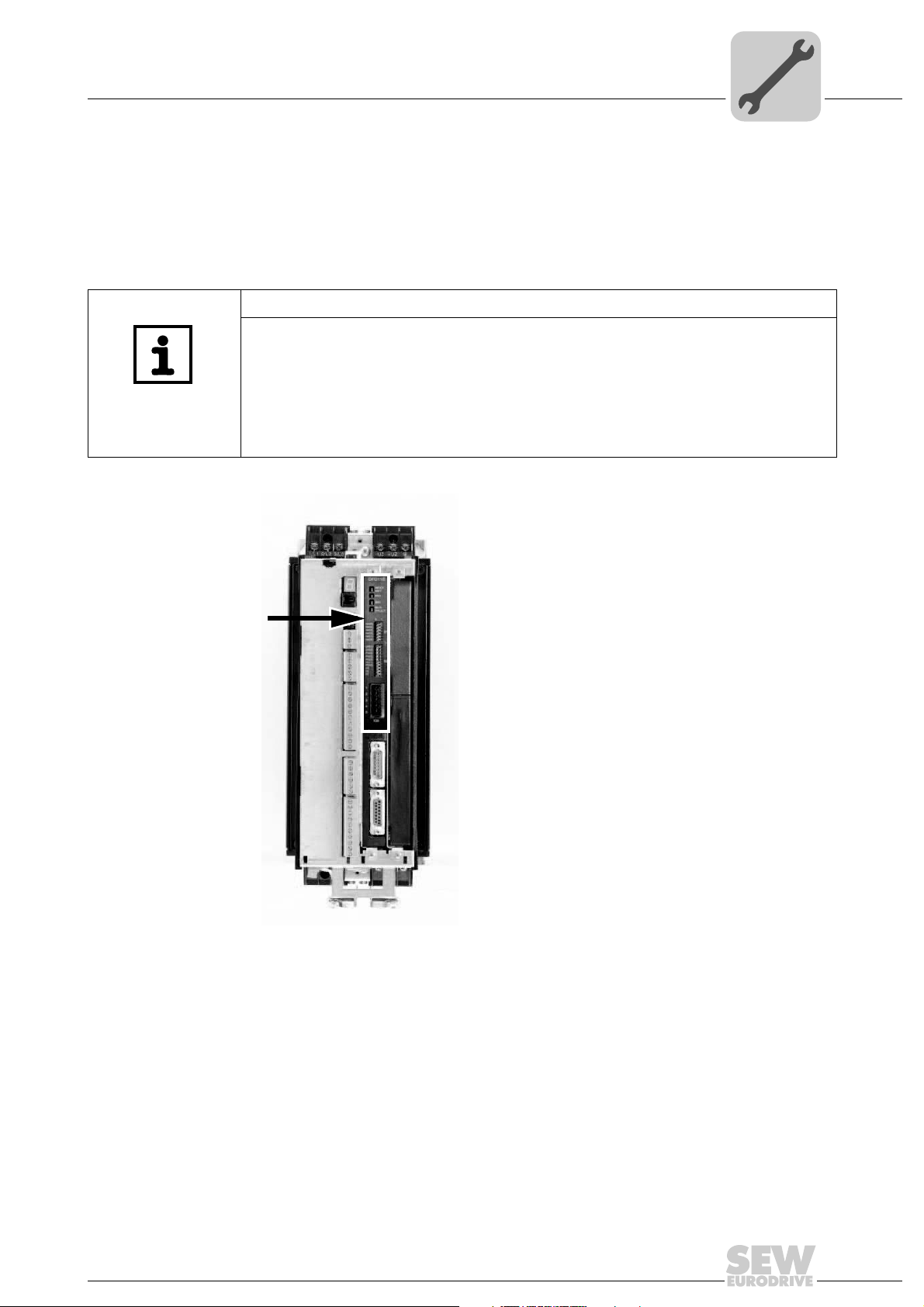
4.1 Installing the DFD11B option card in MOVIDRIVE® MDX61B
NOTES
Only SEW-EURODRIVE personnel may install or remove option cards for
MOVIDRIVE® MDX61B size 0.
• Users may only install or remove option cards for MOVIDRIVE
to 6.
• The DFD11B option card must be plugged into fieldbus slot [1].
• The DFD11B option is powered via MOVIDRIVE
not required.
[1]
®
B. A separate voltage supply is
®
MDX61B sizes 1
Manual – DFD11B DeviceNet Fieldbus Interface
62594AXX
9
Page 10

4
4.1.1 Before you begin
Assembly and Installation
Installing the DFD11B option card in MOVIDRIVE® MDX61B
Read the following notes before installing or removing an option card:
• Disconnect the inverter from the power. Switch off the 24 V DC and the supply voltage.
• Take appropriate measures to protect the option card from electrostatic charge (use
discharge strap, conductive shoes, and so on) before touching it.
• Before installing the option card, remove the keypad and the front cover (→ operating instructions MOVIDRIVE
• After installing the option card, replace the keypad and the front cover (→ operating
instructions MOVIDRIVE
• Keep the option card in its original packaging until immediately before you are ready
to install it.
• Hold the option card by its edges only. Do not touch any components.
®
MDX60B/61B, section 'Installation').
®
MDX60B/61B, section 'Installation').
10
Manual – DFD11B DeviceNet Fieldbus Interface
Page 11

Assembly and Installation
Installing the DFD11B option card in MOVIDRIVE® MDX61B
4.1.2 Basic procedure for installing and removing an option card (MDX61B, BG 1 - 6)
2.
1.
1.
3.
3.
4
2.
3.
4.
4.
60039AXX
1. Remove the two retaining screws holding the card retaining bracket. Pull the card retaining bracket out evenly from the slot (do not twist!).
2. Remove the two retaining screws of the black cover plate on the card retaining bracket. Remove the black cover plate.
3. Position the option card onto the retaining bracket so that the three retaining screws
fit into the corresponding bores on the card retaining bracket.
4. Insert the retaining bracket with installed option card into the slot, pressing slightly so
it is seated properly. Secure the card retaining bracket with the two retaining screws.
5. To remove the option card, follow the instructions in reverse order.
Manual – DFD11B DeviceNet Fieldbus Interface
11
Page 12
4
Assembly and Installation
Installing the DFD11B option card in MOVITRAC® B
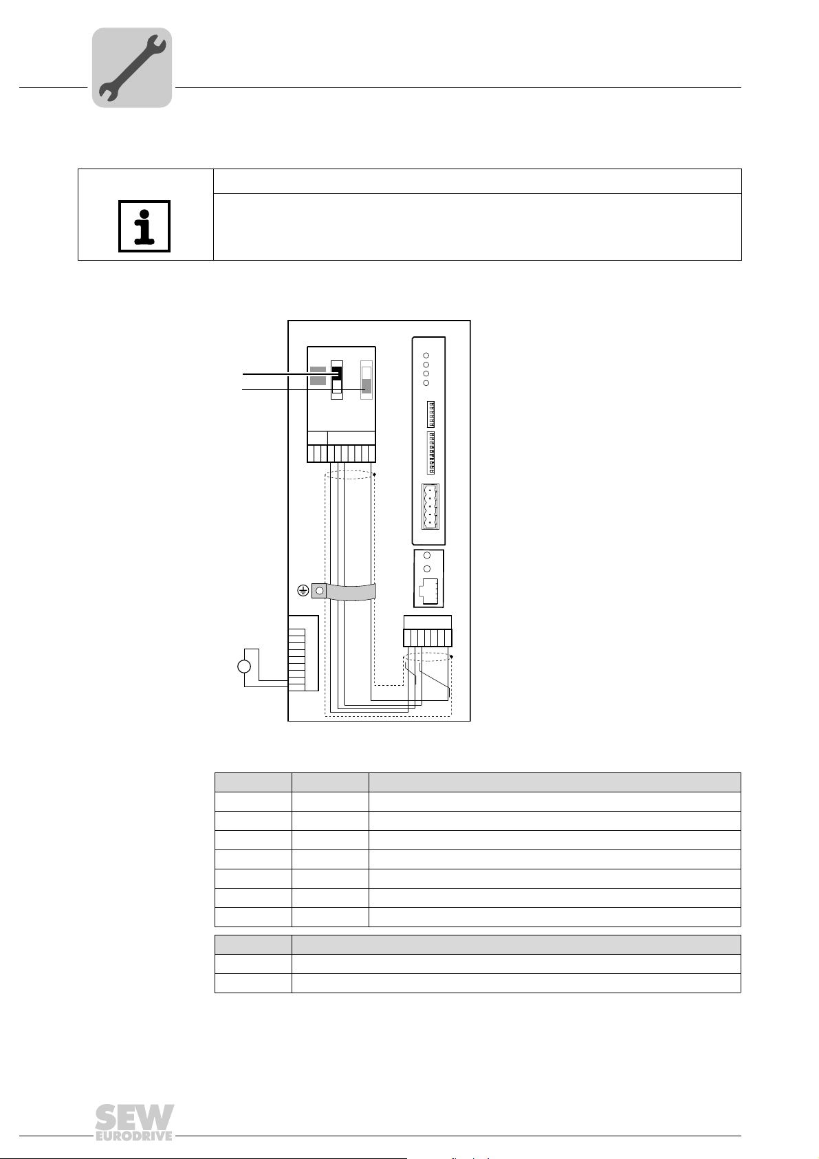
4.2 Installing the DFD11B option card in MOVITRAC® B
NOTE
Only SEW-EURODRIVE engineers may install or remove option cards for
MOVITRAC
4.2.1 System bus connection between a MOVITRAC® B and the DFD11B option
®
B.
24V
[1]
[2]
MOVITRAC® B
S1
S2
ON
OFF
X44
FSC11B
X46
X45
7
23456HL ⊥
1
X12
1
2
3
+
=
24V IO
–
GND
4
5
6
7
8
9
DFD 11B
MOD/
NET
PIO
BIO
BUSFAULT
01
NA(5)
NA(4)
NA(3)
S1
NA(2)
NA(1)
NA(0)
DR(1)
DR(0)
PD(4)
PD(3)
S2
PD(2)
PD(1)
PD(0)
AS
F2
F1
1
2
3
4
5
X30
H1
H2
X24
X26
123456 7
[1] Terminating resistor activated, S1 = ON
[2] DIP switch S2 (reserved), S2 = OFF
62198AXX
12
X46 X26 Terminal assignment
X46:1 X26:1 SC11 SBus +, CAN high
X46:2 X26:2 SC12 SBus –, CAN low
X46:3 X26:3 GND, CAN GND
X26:4 Reserved
X26:5 Reserved
X46:6 X26:6 GND, CAN GND
X46:7 X26:7 DC 24 V
X12 Terminal assignment
X12:8 DC 24 V input
X12:9 GND reference potential for the binary inputs
To simplify cabling, the DFD11B can be supplied with DC 24 V from X46.7 of the
MOVITRAC
®
to X26.7. MOVITRAC® B must be supplied with DC 24 V at terminals
X12.8 and X12.9 when it supplies the DFD11B option. Activate the system bus terminating resistor at the FSC11B option (S1 = ON).
Manual – DFD11B DeviceNet Fieldbus Interface
Page 13
Assembly and Installation
Installing the DFD11B option card in MOVITRAC® B
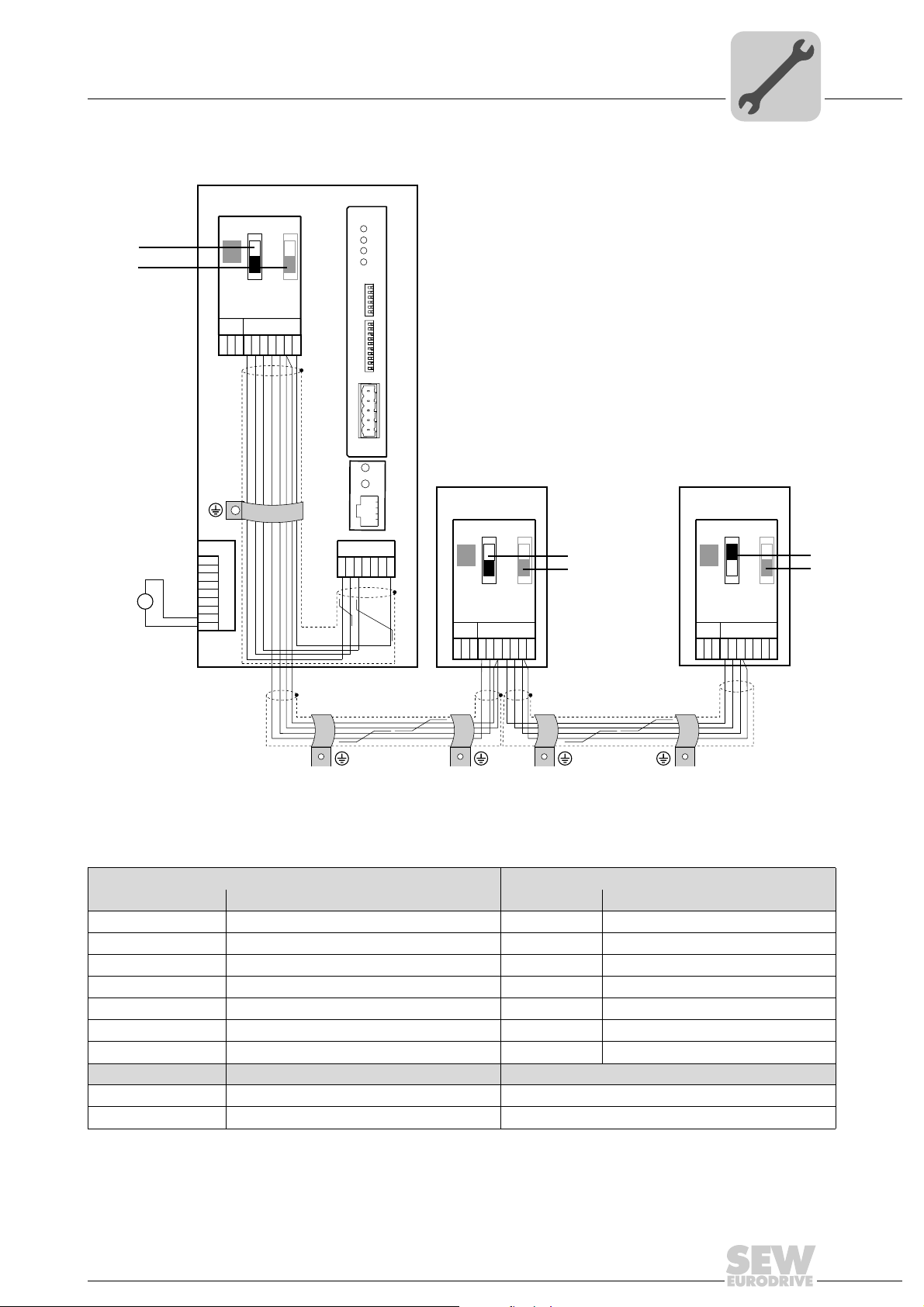
4.2.2 System bus connection between multiple MOVITRAC® B units
4
[1]
[2]
DC 24 V
MOVITRAC® B
DFD 11B
S1
S2
ON
OFF
X44
FSC11B
X46
X45
7
23456HL^
1
X12
1
2
3
+
=
-
24V IO
GND
4
5
6
7
8
9
MOD/
NET
PIO
BIO
BUSFAULT
01
NA(5)
NA(4)
NA(3)
S1
NA(2)
NA(1)
NA(0)
DR(1)
DR(0)
PD(4)
PD(3)
S2
PD(2)
PD(1)
PD(0)
AS
F2
F1
1
2
3
4
5
X30
H1
H2
X24
X26
1234567
MOVITRAC® B
S1
ON
OFF
X44
FSC11B
X46
X45
2345 6HL ^
1
S2
MOVITRAC® B
S1
S2
[1]
[2]
X44
ON
OFF
[1]
[2]
FSC11B
X46
X45
7
1
7
2345 6HL ^
[1] only the terminating resistor at the last unit is activated, S1 = ON
[2] DIP switch S2 (reserved), S2 = OFF
MOVITRAC® B DFD11B via UOH11B gateway housing
X46 Terminal assignment X26 Terminal assignment
X46:1 SC11 (System bus incoming, high) X26:1 SC11 SBus +, CAN High
X46:2 SC12 (System bus incoming, low) X26:2 SC12 SBus –, CAN Low
X46:3 GND (System bus reference) X26:3 GND, CAN GND
X46:4 SC21 (System bus outgoing, high) X26:4 Reserved
X46:5 SC22 (System bus outgoing, low) X26:5 Reserved
X46:6 GND (System bus reference) X26:6 GND, CAN GND
X46:7 DC 24 V X26:7 DC 24 V
X12 Terminal assignment
X12:8 DC 24 V
X12:9 GND (reference potential for the binary inputs)
62602AXX
Manual – DFD11B DeviceNet Fieldbus Interface
13
Page 14
4
Assembly and Installation
Installing the DFD11B option card in MOVITRAC® B
Please note:
• If possible, use a 2x2 core twisted and shielded copper cable (data transmission cable with braided copper shield). Connect the shield on both sides to the electronics
shield clamp of the MOVITRAC
connect the shield ends to the GND. The cable must meet the following specifications:
– Cable cross section 0.25 mm
– Line resistance 120 W at 1 MHz
– Capacitance per unit length
Suitable cables are e.g. CAN bus or DeviceNet cables.
• The permitted total cable length depends on the baud rate setting of the SBus:
– 250 kBaud: 160 m
– 500 kBaud: 80 m
– 1000 kBaud: 40 m
• Connect the system bus terminating resistor (S1 = ON) at the end of the system bus
connection. Switch off the terminating resistor on the other units (S1 = OFF). The
DFD11B gateway must always be connected either at the beginning or the end of the
system bus connection and features a permanently installed terminating resistor.
• Point-to-point wiring is not permitted.
®
B over a large area. Additionally for a 2-core cable,
2
(AWG23) ... 0,75 mm2 (AWG18)
≤ 40 pF/m at 1 kHz
NOTE
• There must not be any potential displacement between the units connected with the
SBus. Take suitable measures to avoid a potential displacement, e.g. by connecting the unit ground connectors using a separate lead.
14
Manual – DFD11B DeviceNet Fieldbus Interface
Page 15

Assembly and Installation
V
Installing the DFE11B / UOH11B gateway
4.3 Installing the DFE11B / UOH11B gateway
The following figure shows the connection of the DFD11B option via the UOH11B:X26
gateway housing.
NOTE
Only SEW-EURODRIVE engineers are allowed to install or remove option cards
in/from the UOH11B gateway housing.
UOH11B
DFD 11B
MOD/
NET
PIO
BIO
BUSFAULT
01
NA(5)
NA(4)
NA(3)
S1
NA(2)
NA(1)
NA(0)
DR(1)
DR(0)
PD(4)
PD(3)
S2
PD(2)
PD(1)
PD(0)
AS
F2
F1
1
2
3
4
5
X30
4
SEW Drive
SC11 Systembus +, CAN high
SC12 Systembus -, CAN low
GND, CAN GND
UOH11B gateway housing
X26 Terminal assignment
X26:1 SC11 system bus +, CAN high
X26:2 SC12 system bus -, CAN low
X26:3 GND, CAN GND
X26:4 Reserved
X26:5 Reserved
X26:6 GND, CAN GND
X26:7 DC 24 V
X26
23456
1
H1
H2
X24
7
DC+24
GND
62197AXX
The gateway housing has a power supply of DC 24 V that is connected to X26.
Connect the system bus terminating resistor at the end of the system bus connection.
Manual – DFD11B DeviceNet Fieldbus Interface
15
Page 16
4
Assembly and Installation
Connection and terminal description DFD11B option
4.4 Connection and terminal description DFD11B option
Part number DeviceNet fieldbus interface type DFD11B: 824 972 5
NOTES
• The DeviceNet fieldbus interface DFD11B option is only possible in conjunction
with MOVIDRIVE
• Plug the DFD11B option into the fieldbus slot.
®
MDX61B, not with MDX60B.
Front view of
DFD11B
DFD 11B
MOD/
NET
PIO
BIO
BUSFAULT
01
NA(5)
NA(4)
NA(3)
NA(2)
NA(1)
NA(0)
DR(1)
DR(0)
PD(4)
PD(3)
PD(2)
PD(1)
PD(0)
AS
F2
F1
S1
S2
1
2
3
4
5
X30
62008AXX
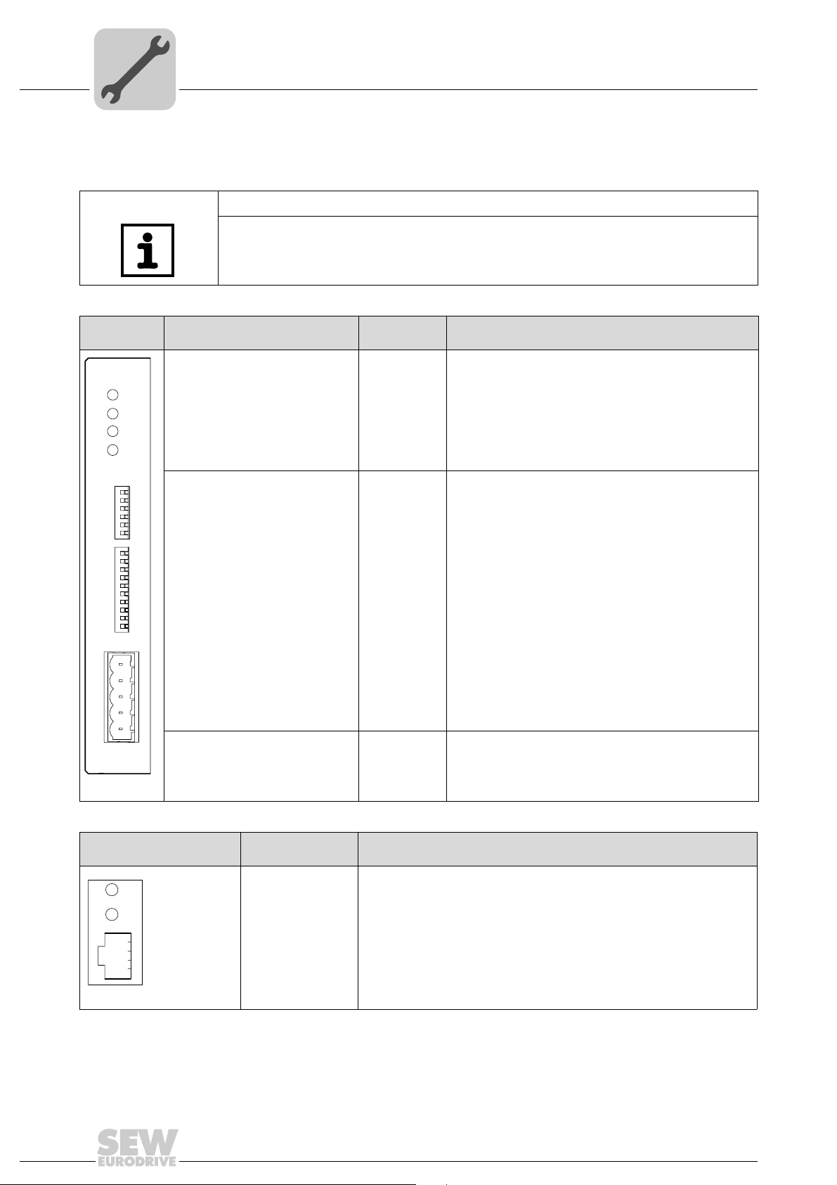
Description
DIP switch
Ter min al
MOD/NET = module/network status
PIO - Polled I/O
BIO - Bit-Strobe I/O
BUS FAULT
Six DIP switches for setting the
NA(0) ... NA(5)
MAC-ID
Two DIP switches for setting the
DR(0) ... DR(1)
baud rate
Five DIP switches for setting the
PD(0) ... PD(4)
process data length
AS
F1, F2
X30: DeviceNet connection X30:1
X30:2
X30:3
X30:4
X30:5
Function
The two-color LEDs display the current status of the fieldbus
interface and the DeviceNet system:
Setting the MAC-ID (Media Access Control Indentifier)
Setting the DeviceNet baud rate:
DR0 = "0"/ DR1 = "0"
DR0 = "1"/ DR1 = "0"
DR0 = "0"/ DR1 = "1"
DR0 = "1"/ DR1 = "1"
Setting the process data length (1 ... 24 words) in
MOVITRAC
Setting the process data length (1 ... 10 words) in
MOVIDRIVE
®
B
®
→ 125 kBaud
→ 250 kBaud
→ 500 kBaud
→ invalid
B
Auto setup for gateway operation
No function
V–
CAN_L
DRAIN
CAN_H
V+
16
Front view of
MOVITRAC
®
H1
H2
X24
B and UOH11B
58129AXX
Description Function
LED H1 (red)
LED H2 (green)
X24 X terminal
System bus error (only for gateway functions)
Reserved
RS-485 interface for diagnostics via PC and MOVITOOLS
®
MotionStudio
Manual – DFD11B DeviceNet Fieldbus Interface
Page 17
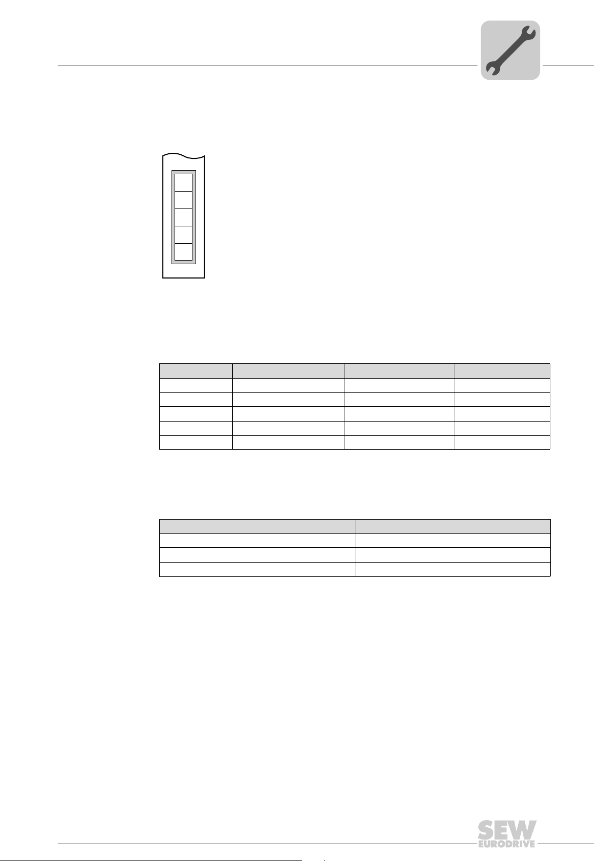
4.5 Pin assignment
The assignment of connecting terminals is described in the DeviceNet specification
(Volume I, Appendix A).
DFD11B
DFD11B
The DFD11B option card is opto-decoupled on the driver side in accordance with the
DeviceNet specification (Volume I, Chapter 9). This means the CAN bus driver must be
powered with 24 V voltage via the bus cable. The cable to be used is also described in
the DeviceNet specification (Volume I, Appendix B). The connection must be made according to the color code specified in the following table.
1
2
3
4
5
X30
Assembly and Installation
Pin assignment
4
54075AXX
DFD11B DeviceNet connection
Pin no. Signal Meaning Color coding
1V– 0V24 BK
2CAN_L CAN_L BU
3 DRAIN DRAIN blank
4CAN_H CAN_H WH
5V+ 24 V RD
According to the DeviceNet Specification a linear bus structure without or with very short
droplines is required.
The maximum permitted cable length depends on the baud rate setting:
Baud rate Maximum cable length
500 kBaud 100 m
250 kBaud 250 m
125 kBaud 500 m
Manual – DFD11B DeviceNet Fieldbus Interface
17
Page 18
4
Assembly and Installation
Shielding and routing bus cables
4.6 Shielding and routing bus cables
The DeviceNet interface supports RS-485 communications protocol and requires cable
type A specified for DeviceNet in accordance with EN 50170 as shielded, twisted-pair
cable for the physical connection.
Correct shielding of the bus cable attenuates electrical interference that may occur in
industrial environments. The following measures ensure the best possible shielding:
• Manually tighten the mounting screws on the connectors, modules, and equipotential
bonding conductors.
• Apply the shielding of the bus cable on both ends over a large surface.
• Route signal and bus cables in separate cable ducts. Do not route them parallel to
power cables (motor leads).
• Use metallic, grounded cable racks in industrial environments.
• Route the signal cable and the corresponding equipotential bonding close to each
other using the shortest possible route.
• Avoid using plug connectors to extend bus cables.
• Route the bus cables closely along existing grounding surfaces.
STOP!
In case of fluctuations in the ground potential, a compensating current may flow via the
bilaterally connected shield that is also connected to the protective earth (PE). Make
sure you supply adequate equipotential bonding according in accordance with relevant
VDE regulations in such a case.
4.7 Bus termination
In order to avoid disruptions in the bus system due to reflections, each DeviceNet segment must be terminated with 120
ical participant. Connect the bus terminating resistor between connections 2 and 4 of the
bus plug.
Ω bus terminating resistors at the first and last phys-
18
Manual – DFD11B DeviceNet Fieldbus Interface
Page 19
Assembly and Installation
Setting the DIP switches
4.8 Setting the DIP switches
NOTE
Before changing a DIP switch setting, disconnect the drive inverter from power (supply
voltage and 24 V backup operation). The DIP switch settings are adopted during initialization of the driver inverter only.
Setting the MAC-IDThe MAC-ID (Media Access Control Identifier) is set on the DFD11B option card with
DIP switches S1-NA0 ... S1-NA5. in a binary coded manner. The MAC-ID represents the
node address of the DFD11B. The DFD11B supports the address range 0 ... 63.
4
Setting the baud
rate
Setting the process data length
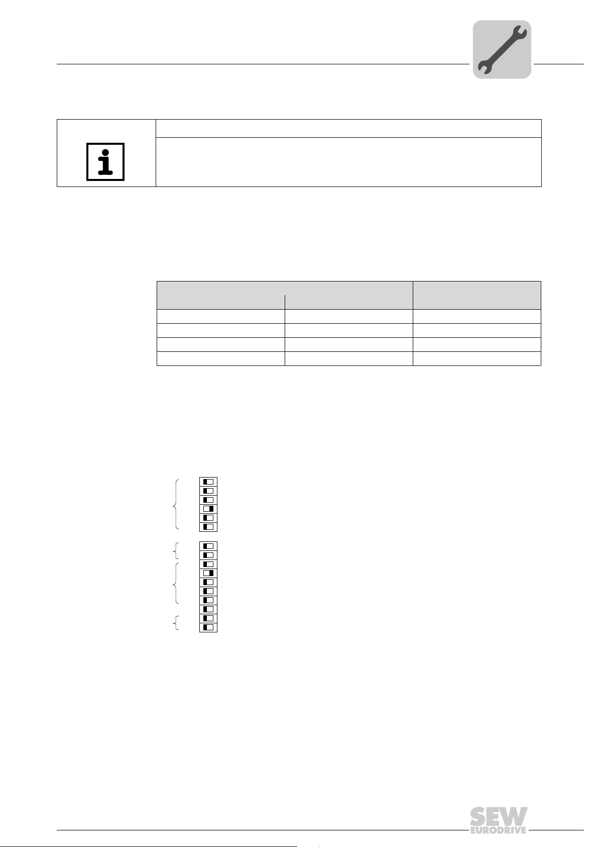
The baud rate is set with DIP switches S2-DR0 and S2-DR1.
DIP switch S2
DR1 DR0
0 0 125 kBaud
0 1 250 kBaud
1 0 500 kBaud
11Invalid
Up to ten data words (DFD11B in MOVIDRIVE
as gateway in MOVITRAC
®
B or UOH11B) can be exchanged between the DeviceNet
®
B) and up to 24 data words (DFD11B
Baud rate
master and the DFD11B. The number is set with DIP switches S2-PD0 to S2-PD4 in a
binary coded manner.
0 1
NA5
[1]
[2]
[3]
[4]
[5]
NA4
NA3
NA2
NA1
NA0
DR1
DR0
PD4
PD3
PD2
PD1
PD0
AS
F2
F1
S1
S2
[1] Setting the MAC-ID
[2] Setting the baud rate
[3] Setting the process data length
[4] Auto setup for gateway operation
[5] No function
The figure depicts the following settings:
MAC-ID: 4
Baud rate: 125 kBaud
Process data length: 8 PD
Configuring the
SBus communication of the
gateway
Manual – DFD11B DeviceNet Fieldbus Interface
The "AS" DIP switch is used to configure the SBus communication of the gateway
(
→ chapter "Auto setup for gateway operation").
The configuration is carried out when the "AS" DIP switch is set from "0" to "1". For further operation, the "AS" DIP switch must remain in position "1" (= ON).
62196AXX
19
Page 20

4
Assembly and Installation
DFD11B option card - status LED
4.9 DFD11B option card - status LED
The DFD11B option card is equipped with four two-color LEDs for diagnostic of the DeviceNet system; these indicate the current status of the DFD11B and the DeviceNet system. The unit status corresponding to the status of the LED is is described in chapter
'Error diagnostics'.
LED abbreviation Complete LED designation
MOD/NET Module/Network Status
PIO Polled I/O
BIO Bit-Strobe I/O
BUS FAULT BusFAULT
MOD/NET LED The function of the LED Mod/Net described in the following table is contained in the De-
viceNet specification.
LED Status Meaning
Off Not switched on / OffLine • Unit is off-line
Flashing green
(1 s cycle)
Green light Online, operational mode
Flashing red
(1 s cycle)
Red light Critical fault or critical link
Online and in operational
mode
and connected
Minor fault or connection
timeout
failure
• Unit performs DUP MAC check
• Unit is switched off
• The unit is on-line and no connection has been established
• DUP MAC check performed successfully
• A connection to a master has not been established yet
• Missing, incorrect or incomplete configuration
•Online
• Connection to a master has been established
• Connection is active (established state)
• A correctable error has occurred
• A device error is active (MOVIDRIVE
• Polled I/O or/and bit-strobe I/O connections are in timeout state
• DUP-MAC check has detected an error
• A correctable error has occurred
• Bus fault
• DUP-MAC check has detected an error
®
B / gateway)
PIO LED The PIO LED checks the polled I/O connection.
LED Status Meaning
Flashing
green
(125 ms
cycle)
Off Not switched on / off-line but
Flashing
green
(1 s cycle)
Green light Online, operational mode
Flashing red
(1 s cycle)
Red light Critical fault or critical link
DUP-MAC check Unit is performing DUP-MAC check
not DUP-MAC check
Online and in operational
mode
and connected
Minor fault or connection timeout
failure
20
• Unit is off-line
• Unit is switched off
• Unit is on-line
• DUP MAC check performed successfully
• A PIO connection to a master is being established
(configuring state)
• Missing, incorrect or incomplete configuration
•Online
• A PIO connection has been established (established
state)
• Invalid baud rate setting via DIP switches
• A correctable error has occurred
• Polled I/O connection is in timeout state
• An error that cannot be remedied has occurred
• Bus fault
• DUP-MAC check has detected an error
Manual – DFD11B DeviceNet Fieldbus Interface
Page 21

Assembly and Installation
DFD11B option card - status LED
BIO LED The BIO LED checks the bit-strobe I/O connection.
LED Status Meaning
Flashing
green
(125 ms
cycle)
Off Not switched on / off-line but
Flashing
green
(1 s cycle)
Green light Online, operational mode
Flashing red
(1 s cycle)
Red light Critical fault or critical link
DUP-MAC check Unit is performing DUP-MAC check
not DUP-MAC check
Online and in operational
mode
and connected
Minor fault or connection timeout
failure
• Unit is off-line
• Unit is switched off
• Unit is on-line
• DUP MAC check performed successfully
• A BIO connection to a master is being established
(configuring state)
• Missing, incorrect or incomplete configuration
•Online
• A BIO connection has been established (established
state)
• Invalid number of process data is set via DIP switches
• A correctable error has occurred
• Bit-strobe I/O connection is in timeout state
• An error that cannot be remedied has occurred
• Bus fault
• DUP-MAC check has detected an error
4
BUS-FAULT LED The BUS-FAULT LED displays the physical status of the bus node.
Status of the
BUS FAULT LED
Off NO ERROR The number of bus errors is in the normal range (error
Flashing red
(125 ms cycle)
Flashing red
(1 s cycle)
Red light BUS ERROR • Bus-fault state
Yellow light POWER OFF External voltage supply via X30 has been turned off or is
Status Meaning
active status).
The unit is performing a DUP-MAC check and cannot
send any messages because no other stations are con-
BUS WARNING
nected to the (bus error passive state)
The number of physical bus errors is too high. No more
error telegrams are actively written to the bus (error passive state).
• The number of physical bus errors has increased
despite a switch to the error-passive state. Access to
the bus is switched off.
not connected.
Power-UP test A power-up test of all LEDs takes place once the drive inverter has been switched on.
The LEDs are switched on in the following sequence:
Time in [ms] MOD/NET LED PIO LED BIO LED BUS FAULT LED
0
250
500 Off
750 Off
1000 Off Off
1250 Off Off
1500 Off Off Off
1750 Off Off Off
2000 Off Off Off Off
Green Off Off Off
Red Off Off Off
Green Off Off
Red Off Off
Green Off
Red Off
Green
Red
Manual – DFD11B DeviceNet Fieldbus Interface
21
Page 22
I
5
Project Planning and Startup
Validity of the EDS files for DFD11B
00
5 Project Planning and Startup
This section provides you with information on project planning for the DeviceNet master
and startup of the drive inverter for fieldbus operation.
NOTE
The current version of the EDS file for the DFD11B option card is available on the SEW
homepage (http://www.sew-eurodrive.de) under the heading "Software".
5.1 Validity of the EDS files for DFD11B
NOTE
Entries in the EDS file must not be changed or expanded. SEW assumes no liability
for inverter malfunctions caused by a modified EDS file!
Two different EDS files are available for the configuration of the master (DeviceNetScanner) for the DFD11B:
• if DFD11B is used as a fieldbus option in MOVIDRIVE
SEW_MOVIDRIVE_DFD11B.eds is required
• if DFD11B is used as a gateway in MOVITRAC
(UOH11B), the EDS file SEW_GATEWAY_DFD11B.eds is required
Install the following files with the RSNetWorx software to build the DeviceNet network
with the DFD11B option: Proceed as follows:
• Select the menu item <Tools/EDS-Wizard> in RSNetWorx. You will be prompted to
enter the names of the EDS and Icon file.
• The files will be installed. For detailed information on the installation of the EDS file,
refer to the Allen Bradley documentation for RSNetWorx.
• After installation, the device is available in the device list under the entry "Vendor/SEW EURODRIVE GmbH".
®
B or in the gateway housing
®
B, the EDS file
22
Manual – DFD11B DeviceNet Fieldbus Interface
Page 23
Project Planning and Startup
Configuring PLC and master (DeviceNet scanner)
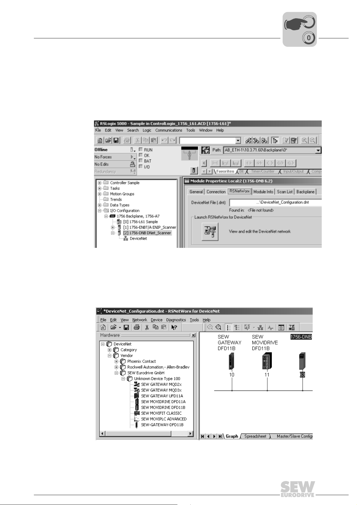
5.2 Configuring PLC and master (DeviceNet scanner)
The following samples refer to the usage of an Allen-Bradley-PLC ControlLogix 1756L61 together with the RSLogix 5000 programming software and the DeviceNet
RSNetWorx configuration software for DeviceNet.
After adding the DeviceNet Scanner to the I/O configuration, the file *.dnt containing the
DeviceNet configuration is selected. To view and edit the DeviceNet configuration,
RSNetWorx can be launched from this dialog (→
I
5
00
following figure).
11744AXX
In RSNetWorx for DeviceNet (→
the required devices to the graph by drag and drop. The address given under the icon
of the device must be equal to the MAC-ID set by the DIP switches of the DFD11B. If
the required devices are not in the selection list, corresponding EDS files have to be registered via [Tools] / [Wizard].
following figure), either perform an online scan or add
Manual – DFD11B DeviceNet Fieldbus Interface
11745AXX
23
Page 24

I
5
Project Planning and Startup
Configuring PLC and master (DeviceNet scanner)
00
5.2.1 DFD11B as fieldbus option in MOVIDRIVE® B
By reading the device properties in online mode, the process data (Pd) configuration of
the DFD11B can be checked (→
following figure).
11746AXX
The parameter 'Pd configuration' gives the number (1 ... 10) of process data words (PD)
set via DIP switches PD(0) ... PD(4)and defines the I/O parameter for the DeviceNet
scanner (→
following figure).
24
11747AXX
Manual – DFD11B DeviceNet Fieldbus Interface
Page 25

Project Planning and Startup
I
Configuring PLC and master (DeviceNet scanner)
00
After adding the MOVIDRIVE® B with DFD11B to the scanlist, the number of Polled I/O
Bytes must be set to 2 × number of PD (e. g. number of PD = 3 ×
Bytes = 6 and output-Bytes = 6) via [Edit I/O Parameters]. When the DeviceNet configuration is saved and downloaded into the scanner, RSNetWorx can be closed.
Depending on the DeviceNet configuration and the mapping rules in the scanner, the
data from and to DeviceNet units is packed into a DINT-Array that is transferred from
the scanner to the local I/O tags of the Logix-Processor.
In order not to have to search for the data from a certain device in this array manually,
the 'DeviceNet Tag Generator' tool generates copy commands and two controller tags
(Input & Output) for each DeviceNet device as a byte-array.
The tag-name contains the MAC-ID of the DeviceNet unit and 'POL_I' for polled input
data or 'POL_O' for polled output data (→
following figure).
number of polled input-
5
11748AXX
The content of the process data words 1 ... 3 from and to MOVIDRIVE
parameter P870 ... P875. The content of the process data words 4 ... 10 is defined by
an IPOS
plus®
program or an application module.
®
B is defined via
Manual – DFD11B DeviceNet Fieldbus Interface
25
Page 26

I
5
Project Planning and Startup
Configuring PLC and master (DeviceNet scanner)
00
5.2.2 DFD11B as fieldbus gateway in MOVITRAC® B or UOH11B gateway housing
By reading the device properties in online mode, the process data (Pd) configuration of
the DFD11B can be checked (→
following figure).
11749AXX
The parameter 'Pd configuration' gives the number (3 ... 24) of process data words (PD)
set via DIP switches PD(0) ... PD(4). The number of process data words must be 3 ×
number of drives (1 ... 8) connected via SBus to the DFD11B gateway. The number of
PD then gives the I/O parameter for the DeviceNet Scanner (→
following figure).
26
11750AXX
Manual – DFD11B DeviceNet Fieldbus Interface
Page 27

Project Planning and Startup
I
Configuring PLC and master (DeviceNet scanner)
00
After adding the DFD11B gateway to the scanlist, the number of polled I/O Bytes must
be set to 2 ×
and output-Bytes = 12) via 'Edit I/O Parameters'. When the DeviceNet configuration is
saved and downloaded into the scanner, RSNetWorx can be closed.
Depending on the DeviceNet configuration and the mapping rules in the scanner, the
data from and to DeviceNet units is packed into a DINT-Array that is transferred from
the scanner to the local I/O tags of the Logix-Processor.
In order not to have to search for the data from a certain device in this array manually,
the 'DeviceNet Tag Generator' tool generates copy commands and two controller tags
(Input & Output) for each DeviceNet device as a byte-array.
The tag-name contains the MAC-ID of the DeviceNet unit and 'POL_I' for polled input
data or 'POL_O' for polled output data (→
number of PD (e. g. number of PD = 6 × number of polled input-Bytes = 12
following figure).
5
11751AXX
In this Byte arrays from and to the DFD11B gateway the data is transferred to the drives
connected to the SBus of this gateway as follows:
• Byte 0 ... 5 contain PD 1 ... 3 of the drive with the lowest SBus address (e. g. 1)
• Byte 6 ... 11 contain PD 1 ... 3 of the drive with the next higher SBus address (e. g. 2)
The content of process data word 1 ... 3 from and to the drives is defined in each drive
individually via parameter P870 ... P875.
Manual – DFD11B DeviceNet Fieldbus Interface
27
Page 28

I
5
Project Planning and Startup
Configuring PLC and master (DeviceNet scanner)
00
5.2.3 Auto setup for gateway operation
The auto setup function lets you start up the DFD11B as gateway without a PC. The
function is activated via the Auto Setup DIP switch (see section 4.4 page 16)
NOTE
Setting the Auto-Setup DIP switch (AS) from OFF to ON position causes the function
to be executed once. The Auto Setup DIP switch must then remain in the ON po-
sition.The function can be reactivated by turning the DIP switch off and back on again.
As a first step, the DFD11B searches for drive inverters on the lower-level SBus. This
process is indicated by the H1 LED (system bus error) flashing briefly. For this purpose,
different SBus addresses must be set for the drive inverters (P881). We recommend assigning the addresses beginning with address 1 in ascending order based on the arrangement of inverters in the switch cabinet. The process image on the fieldbus side is
expanded by three words for each detected drive inverter.
The H1 LED remains lit if no drive inverter was located. A total of up to eight drive inverters is taken into account.
After the search is completed, the DFD11B periodically exchanges three process data
words with each connected drive inverter. The process output data are fetched from the
fieldbus, divided into blocks of three and transmitted. The drive inverters read the process input data, put them together and send them to the fieldbus master.
The cycle time of the SBus communication is 2 ms per node at a baud rate of 500 kBit/s
without any additional engineering activities.
Thus, for an application with 8 inverters on the SBus, the cycle time of the process data
update is then 8 x 2 ms = 16 ms.
NOTE
If you change the process data assignment of the drive inverters connected to the
DFD11B, you have to activate Auto Setup again because the DFD11B saves these
values only once during Auto Setup. The process data assignments of the connected
drive inverters may not be changed dynamically after Auto Setup.
28
Manual – DFD11B DeviceNet Fieldbus Interface
Page 29

Project Planning and Startup
Configuring the MOVIDRIVE® MDX61B drive inverter
5.3 Configuring the MOVIDRIVE® MDX61B drive inverter
The following settings are required for simple fieldbus operation.
I
5
00
11638AXX
®
However, to control the MOVIDRIVE
switch the drive inverter to control signal source (P101) and setpoint source (P100) =
FIELDBUS. The FIELDBUS setting means the drive inverter parameters are set for control and setpoint entry via DeviceNet. The MOVIDRIVE
to the process output data transmitted by the PLC.
The parameters of the MOVIDRIVE
viceNet without any further settings once the DeviceNet option card has been installed.
For example, all parameters can be set by the PLC after power-on.
Activation of the control signal source and setpoint source FIELDBUS is signaled to the
machine controller using the "Fieldbus mode active" bit in the status word.
For safety reasons, you must also enable the MOVIDRIVE
minals for control via the fieldbus system. Therefore, you must wire and program the terminals in such a way that the inverter is enabled via the input terminals. For example,
the simplest way of enabling the drive inverter at the terminals is to connect the DIØØ
(function / CONTROLLER INHIBIT) input terminal to a DC +24 V signal and to program
input terminals DIØ1 ... DIØ7 to NO FUNCTION.
B drive inverter via DeviceNet, you must first
®
B drive inverter then responds
®
B drive inverter can be set straight away via De-
®
B drive inverter at the ter-
Manual – DFD11B DeviceNet Fieldbus Interface
29
Page 30

I
5
Project Planning and Startup
Configuring the MOVITRAC® B frequency inverter
00
5.4 Configuring the MOVITRAC® B frequency inverter
11845AXX
To control the MOVITRAC® B frequency inverter via DeviceNet, you must switch the
drive inverter to control signal source (P101) and setpoint source (P100) = SBus beforehand. The SBus setting means the MOVITRAC
and setpoint entry via gateway. The MOVITRAC
data transmitted by the PLC.
It is necessary to set the SBus1 timeout interval (P883) to a value other than 0 ms for
the MOVITRAC
recommend a value in the range 50 ... 200 ms. Activation of the control signal source
and setpoint source SBus is signaled to the higher-level controller using the "SBus mode
active" bit in the status word.
For safety reasons, you must also enable the MOVITRAC
via the fieldbus system. Therefore, you must wire and program the terminals in such a
way that the MOVITRAC
abling the MOVITRAC
CW/STOP) input terminal to a +24-V signal and to program the remaining input terminals to NO FUNCTION.
®
B inverter to stop if faulty SBus communication is encountered. We
®
B is enabled via the input terminals. The simplest way of en-
®
B at the terminals is, for example, to connect the DIØ1 (function
®
B parameters are set for control
®
B then responds to the process output
®
B at the terminals for control
NOTE
Set the parameter P881 SBus address to values between 1 to 8 in ascending order 8.
A MOVITRAC
(as of firmware .15).
The SBus address 0 is used by the DFD11B gateway and must therefore not be used.
Set P883 SBus timeout to values between 50 ... 200 ms
®
B with integrated DFD11B has the SBus address 1 as factory setting
30
Manual – DFD11B DeviceNet Fieldbus Interface
Page 31

Project Planning and Startup
Programming samples in RSLogix 5000
5.5 Programming samples in RSLogix 5000
5.5.1 MOVIDRIVE® B with 3 PD data exchange
1. Set the DIP switches on the DFD11B to
• adjust the baud rate to the DeviceNet network
• set the address (MAC-ID) to a value used by no other node
• set the number of PD (according to this sample) to 3
2. Then follow chapter 5.2 and 5.2.1 to add MOVIDRIVE
viceNet configuration.
3. Follow chapter 5.3 to set the communication parameters of MOVIDRIVE
4. Now the integration into the RSLogix project can performed.
Generate a controller tag with a user-defined data type to get a plain interface to the
inverters process data (→
following figure)
I
00
®
B with DFD11B to the De-
®
B.
5
The description for PI and PO data can be assigned to the controller tag fitting to the
definitions made in MOVIDRIVE
Manual – DFD11B DeviceNet Fieldbus Interface
®
B (→ chapter 5.3).
11752AXX
11753AXX
31
Page 32

5
I
Project Planning and Startup
Programming samples in RSLogix 5000
00
5. In order to copy the data from the drive to the new data structure, a CPS command
is added into the 'MainRoutine' that reads the data from the local I/O (→ following figure).
Make sure that this CPS command is executed after the automatically (by DeviceNet
Tag Generator) generated DNet_ScannerInputsRoutine.
11754AXX
In order to copy the data from the new data structure to the drive, a CPS command
is added into the 'MainRoutine' that writes the data to the local I/O.
Make sure that this CPS command is executed before the automatically (by
DeviceNet Tag Generator) generated DNet_ScannerOutputsRoutine.
32
11755AXX
Manual – DFD11B DeviceNet Fieldbus Interface
Page 33

Project Planning and Startup
I
Programming samples in RSLogix 5000
00
6. Finally save and download the project to the PLC. set the PLC to Run Mode and set
the Scanner CommandRegister.Run to '1' to activate the data exchange via DeviceNet.
Now the actual values from the device can be read and setpoint values can written.
5
11756AXX
The data in the controller tags should be equal to the process data displayed in the
parameter tree of MOVITOOLS
®
MotionStudio (→ following figure).
11757AXX
Manual – DFD11B DeviceNet Fieldbus Interface
33
Page 34

I
5
Project Planning and Startup
Programming samples in RSLogix 5000
00
5.5.2 Two MOVITRAC® B via DFD11B / UOH11B gateway
1. Set the DIP switches on the DFD11B to
• adjust the baud rate to the DeviceNet network
• set the address (MAC-ID) to a value used by no other node
• set the number of PD (according to this sample) to 6
2. Then follow chapter 5.2 and 5.2.2 to add the DFD11B gateway to the DeviceNet configuration.
3. Execute the Auto Setup Function of the DFD11B gateway according to chapter 5.3
to configure the data-mapping to the drives.
4. Follow chapter 5.4 to set the communication parameters of MOVITRAC
5. Now the integration into the RSLogix project can performed.
Generate a controller tag with a user-defined data type to get a plain interface to the
inverters process data (→
following figure)
®
B.
11752AXX
The description for PI and PO data can be assigned to the controller tag fitting to the
definitions made in MOVITRAC
®
B (→ chapter 5.4).
11758AXX
34
Manual – DFD11B DeviceNet Fieldbus Interface
Page 35

Project Planning and Startup
I
Programming samples in RSLogix 5000
00
6. In order to copy the data from the drive to the new data structure, CPS commands
are added into the 'MainRoutine' that read the data from the local I/O (→
figure).
Make sure that these CPS commands are executed after the automatically (by
DeviceNet Tag Generator) generated DNet_ScannerInputsRoutine.
following
5
Please note that the structure DNet_Scanner_N10_POL_I.Data contains the PD
from all drives on the gateway, so that the 6 data bytes of each drive have to be copied from the structure with a specific offset: [0], [6], [12] ... [42].
Manual – DFD11B DeviceNet Fieldbus Interface
11759AXX
35
Page 36

5
I
Project Planning and Startup
Programming samples in RSLogix 5000
00
In order to copy the data from the new data structure to the drive, CPS commands
are added into the 'MainRoutine' that write the data to the local I/O.
Make sure that these CPS commands are executed before the automatically (by
DeviceNet Tag Generator) generated DNet_ScannerOutputsRoutine.
11760AXX
Please note that the structure DNet_Scanner_N10_POL_O.Data contains the PD to
all drives on the gateway, so that the 6 data bytes of to each drive have to be copied
to the structure with a specific offset: [0], [6], [12] ... [42].
7. Finally save and download the project to the PLC. set the PLC to Run Mode and set
the Scanner CommandRegister.Run to '1' to activate the data exchange via
DeviceNet.
Now the actual values from the device can be read and setpoint values can written
(→
following figure).
36
11761AXX
Manual – DFD11B DeviceNet Fieldbus Interface
Page 37

Project Planning and Startup
Programming samples in RSLogix 5000
I
5
00
The data in the controller tags should be equal to the process data displayed in the
monitor for the DFx fieldbus gateway or in the parameter tree in MOVITOOLS
MotionStudio (→ following figures).
11762AXX
®
Manual – DFD11B DeviceNet Fieldbus Interface
11763AXX
37
Page 38

I
5
Project Planning and Startup
Programming samples in RSLogix 5000
00
5.5.3 MOVIDRIVE® B parameter access
In order to get an easy-to-use read access to parameters of the MOVIDRIVE
plicit messages and the register object, follow the following steps:
1. Generate the user-defined data structure 'SEW_Parameter_Channel' (
figure)
®
B via ex-
→ following
2. Define the controller tags (→
3. Create a Rung for the ReadParameter execution (→
• For contact, select the tag 'ReadParameterStart'
• For the Message Control, select the tag 'ReadParameter'
following figure).
11764AXX
11765AXX
following figure).
11766AXX
38
Manual – DFD11B DeviceNet Fieldbus Interface
Page 39

Project Planning and Startup
I
Programming samples in RSLogix 5000
00
4. Click on in the MSG instruction to open the Message Configuration Window
(
→ following figure).
11767AXX
Select 'CIP Generic' as message type. Fill in the further data in the following order:
A Source Element = ReadParameterRequest.Index
B SourceLength = 12
C Destination = ReadParameterResponse.Index
D Class = 7
E Instance = 1
F Attribute = 4
G Service Code = e
The Service Type is set automatically.
hex
hex
hex
5
5. The target device is to be specified on the Communication tab (→
The path consists of:
• Name of the scanner (e. g. DNet_Scanner)
• 2 (always 2)
• Slave address (e. g. 11 bit)
following figure).
11768AXX
Manual – DFD11B DeviceNet Fieldbus Interface
39
Page 40

5
I
Project Planning and Startup
Programming samples in RSLogix 5000
00
6. After downloading the changes to the PLC, the index of the parameter to be read can
be entered at ReadParameterRequest.Index. By altering ReadParameterStart to '1'
the read request is executed once (
→ following figure).
11769AXX
On response to the read request, ReadParameterResponse.Index should indicate
the read index and ReadParameterResponse.Data should contain the read data. In
this sample P160 internal setpoint n11 (Index 8489) has the value of 150 rpm.
In the MOVITOOLS
tooltip of a parameter displays e. g. index, subindex, scaling ... of a parameter.
The complete list of index numbers and scaling factors can be taken from
MOVIDRIVE
®
®
MotionStudio parameter tree, the value can be checked. The
Fieldbus Unit Profile manual.
11770AXX
40
Manual – DFD11B DeviceNet Fieldbus Interface
Page 41

Project Planning and Startup
Programming samples in RSLogix 5000
Only few changes are required for parameter write access:
• Define the controller tags (
• Create a rung for the WriteParameter execution (→
For contact, select the tag 'WriteParameterStart'
For the Message Control, select the tag 'WriteParameter'
→ following figure).
following figure).
I
5
00
11771AXX
11772AXX
• Click on in the MSG instruction to open the Message Configuration Window
(
→ following figure).
11773AXX
Fill in the data in the following order:
– Source Element = WriteParameterRequest.Index
– Source Length = 12
– Destination = WriteParameterResponse.Index
– Class = 7
– Instance = 2
– Attribute = 4
– Service Code = 10
hex
hex
hex
Manual – DFD11B DeviceNet Fieldbus Interface
41
Page 42

5
I
Project Planning and Startup
Programming samples in RSLogix 5000
00
7. After downloading the changes to the PLC, index and value to be written into the parameter can be entered at WriteParameterRequest.Index and WriteParameterRe-
quest.Data. By altering WriteParameterStart to '1' the write request is executed once
(
→ following figure).
42
11774AXX
On response to the write request, WriteParameterResponse.Index should give the
written index and WriteParameterResponse.Data should contain the written data. In
this sample P160 internal setpoint n11 (Index 8489) has the value of 200 rpm.
In the MOVITOOLS
tooltip of a parameter displays e. g. index, subindex, scaling ... of a parameter.
®
MotionStudio parameter tree, the value can be checked. The
Manual – DFD11B DeviceNet Fieldbus Interface
Page 43

Project Planning and Startup
Programming samples in RSLogix 5000
5.5.4 MOVITRAC® B parameter access via DFD11B / UOH11B
®
The access to MOVITRAC
DFD11B/UOH11B is identical to the access to MOVIDRIVE
(→
chapter 5.5.3).
The only difference is, that Read/WriteParameterRequest.SubChannel1 is to be set
to 2 and Read/WriteParameterRequest.SubAddress1 is to be set to the SBus ad-
dress of the MOVITRAC
B parameter data via DeviceNet-SBus Gateway
®
B connected to the DFD11B/UOH11B (→ following figure).
®
B parameter data
I
5
00
In this sample, MOVITRAC
7 read the value 150 rpm from P160 Internal Setpoint n11 (Index 8489).
Manual – DFD11B DeviceNet Fieldbus Interface
11775AXX
®
B connected to the DFD11B-Gateway with SBus address
43
Page 44

.
.
.
I
5
Project Planning and Startup
Programming samples in RSLogix 500 for SLC 500
00
5.6 Programming samples in RSLogix 500 for SLC 500
Power section
Chassis 1746-A7
Terminating
resistor
1485A-C2
RSLogic500 for SLC
9324-RL0300END
PC PC
RS232C
1747-CP3
SLC500Power section
1746-P2
MAC-ID
0
123
4
56
789
0
+/-
RS232C
1747-CP3
16
outputs16inputs
1747-SDN 1746-IB16
DeviceNet (remote line 1485C-P1-A50)
MAC-ID
8
DeviceNet
Scanner
1
1746-OB161747-L542
MAC-ID
123
4
56
789
0
+/-
System configuration
DeviceNet
MAC-ID
1
11
Adapter
16
inputs
1794-ADN 1794-IB16 1794-ADN 1794-OV16
MAC-ID
4
123
4
56
789
0
+/-
MAC-ID
Terminal module
1794-TB2
10
Adapter
16
inputs
Terminal module
1794-TB2
1485A-C2
Terminating
resistor
Figure 1: PLC equipment configuration
The following devices are used:
Unit MAC-ID
SLC5/04 -
DeviceNet scanner 1747-SDN 1
INPUT module with 32 inputs -
OUTPUT module with 32 outputs -
DeviceNet adapter with input module with 16 inputs 11
DeviceNet with output module 16 outputs 10
MOVIDRIVE
MOVIDRIVE
MOVIDRIVE
®
MDX61B with DFD11B 8
®
MDX61B with DFD11B 0
®
MDX61B with DFD11B 4
54179AEN
44
Manual – DFD11B DeviceNet Fieldbus Interface
Page 45

Project Planning and Startup
Programming samples in RSLogix 500 for SLC 500
00
The following memory areas have been specified with the DeviceNet manager software:
*******************************************************************
1747-SDN Scanlist Map
******************************************************************
Discrete Input Map:
15 14 13 12 11 10 09 08 07 06 05 04 03 02 01 00
I:3.000 RRR R RR RRRRRRRRRRStatus word of the scanner
I: 3.001 11 11 11 11 11 11 11 11 11 11 11 11 11 11 11 11 Process data from device 11
I: 3.002 11 11 11 11 11 11 11 11 11 11 11 11 11 11 11 11 Process data from device 11
I:3.003 10 10 10 10 10 10 10 10 10 10 10 10 10 10 10 10 Process data from device 10
I:3.004 10 10 10 10 10 10 10 10 10 10 10 10 10 10 10 10 Process data from device 10
I:3.005 08 08 08 08 08 08 08 08 08 08 08 08 08 08 08 08 PID1 device 8 Polled I/O
I:3.006 08 08 08 08 08 08 08 08 08 08 08 08 08 08 08 08 PID2 device 8 Polled I/O
I:3.007 08 08 08 08 08 08 08 08 08 08 08 08 08 08 08 08 PID3 device 8 Polled I/O
I:3.008 08 08 08 08 08 08 08 08 08 08 08 08 08 08 08 08 PID1 device 8 Bit-Strobe I/O
I:3.009 08 08 08 08 08 08 08 08 08 08 08 08 08 08 08 08 PID2 device 8 Bit-Strobe I/O
I:3.010 08 08 08 08 08 08 08 08 08 08 08 08 08 08 08 08 PID3 device 8 Bit-Strobe I/O
I:3.011 00 00 00 00 00 00 00 00 00 00 00 00 00 00 00 00 PID1 device 0 Polled I/O
I:3.012 00 00 00 00 00 00 00 00 00 00 00 00 00 00 00 00 PID2 device 0 Polled I/O
I:3.013 00 00 00 00 00 00 00 00 00 00 00 00 00 00 00 00 PID3 device 0 Polled I/O
I:3.014 00 00 00 00 00 00 00 00 00 00 00 00 00 00 00 00 PID1 device 0 Bit-Strobe I/O
I:3.015 00 00 00 00 00 00 00 00 00 00 00 00 00 00 00 00 PID2 device 0 Bit-Strobe I/O
I:3.016 00 00 00 00 00 00 00 00 00 00 00 00 00 00 00 00 PID3 device 0 Bit-Strobe I/O
I:3.017 04 04 04 04 04 04 04 04 04 04 04 04 04 04 04 04 PID1 device 4 Polled I/O
I:3.018 04 04 04 04 04 04 04 04 04 04 04 04 04 04 04 04 PID2 device 4 Polled I/O
I:3.019 04 04 04 04 04 04 04 04 04 04 04 04 04 04 04 04 PID3 device 4 Polled I/O
I:3.020 04 04 04 04 04 04 04 04 04 04 04 04 04 04 04 04 PID1 device 4 Bit-Strobe I/O
I:3.021 04 04 04 04 04 04 04 04 04 04 04 04 04 04 04 04 PID2 device 4 Bit-Strobe I/O
I:3.022 04 04 04 04 04 04 04 04 04 04 04 04 04 04 04 04 PID3 device 4 Bit-Strobe I/O
I
5
Discrete Output Map:
15 14 13 12 11 10 09 08 07 06 05 04 03 02 01 00
O:3.000 R RR R RRRRRRRRRRRRControl word of the scanner
O: 3.001 11 11 11 11 11 11 11 11 11 11 11 11 11 11 11 11 Process data to device 11
O:3.002 10 10 10 10 10 10 10 10 10 10 10 10 10 10 10 10 Process data to device 10
O:3.003 08 08 08 08 08 08 08 08 08 08 08 08 08 08 08 08 POD1 device 8 Polled I/O
O:3.004 08 08 08 08 08 08 08 08 08 08 08 08 08 08 08 08 POD2 device 8 Polled I/O
O:3.005 08 08 08 08 08 08 08 08 08 08 08 08 08 08 08 08 POD3 device 8 Polled I/O
O:3.006 00 00 00 00 00 00 00 00 00 00 00 00 00 00 00 00 POD1 device 0 Po
O:3.007 00 00 00 00 00 00 00 00 00 00 00 00 00 00 00 00 POD2 device 0 Polled I/O
O:3.008 00 00 00 00 00 00 00 00 00 00 00 00 00 00 00 00 POD3 device 0 Polled I/O
O:3.009 04 04 04 04 04 04 04 04 04 04 04 04 04 04 04 04 POD1 device 4 Polled I/O
O:3.010 04 04 04 04 04 04 04 04 04 04 04 04 04 04 04 04 POD2 device 4 Polled I/O
O:3.011 04 0404 04 0404 04040404040404040404POD3 device 4 Polled I/O
O:3.012 .. .. .. .. .. .. .. .. .. .. .. .. .. .. .. .. Bit-Strobe for device 8
lled I/O
The Bit-Strobe data are contrasted to the Polled I/O data in bold.
Manual – DFD11B DeviceNet Fieldbus Interface
45
Page 46

I
5
Project Planning and Startup
Programming samples in RSLogix 500 for SLC 500
00
5.6.1 Exchange of polled I/O (process data) with MOVIDRIVE® B
Task In the following program, process data are to be sent to a MOVIDRIVE
the motor should run at a different speed. The program sequence is shown in the following figure.
Cycle 0
®
MDX61B and
START
Speed = 1000 rpm,
Enable
Cycle 1
Speed = 0 rpm,
Rapid stop
Cycle 2
Speed = -400 rpm,
Enable
Cycle 3
Speed = 0 rpm,
Rapid stop
46
The parameters listed in the following table must be set in the MOVIDRIVE
drive inverter for exchange of the process data.
Menu no. Index Parameter Value
100 8461 Setpoint source Fieldbus
101 8462 Control signal source Fieldbus
870 8304 Process output data description 1 Control word 1
871 8305 Process output data description 2 Speed
872 8306 Process output data description 3 No function
873 8307 Process output data description 1 Status word 1
874 8308 Process output data description 2 Speed
875 8309 Process output data description 3 No function
876 8622 PO data enable YES
®
MOVIDRIVE
MDX61B now works in fieldbus mode and can receive process data. The
program can now be written for the SLC500.
Manual – DFD11B DeviceNet Fieldbus Interface
54178AEN
®
MDX61B
Page 47

Programming samples in RSLogix 500 for SLC 500
Start DeviceNet communication
Status engine for control of sense of rotation
Output of the status engine
If status > 3, change to status 0
Project Planning and Startup
I
5
00
Output bit O:3.0/0 is set in rung 0 (program line 0), thereby starting DeviceNet communication (
→ description of the DeviceNet scanner).
Rungs 1 and 3 implement the status engine with which states 0... 3 are implemented.
The current status is written to the outputs O:1.0 of the output module of the SLC500 in
rung 2.
The process data values are output to the scanner memory area in the following figure.
If status > 3, change to status 0
Status 0: Start motor, speed = 1000 rpm
Status 1: Stop motor
01912AEN
Status 0 is created in rung 4. In this status, a 6 (ENABLE) is written to memory area
Manual – DFD11B DeviceNet Fieldbus Interface
01913AEN
47
Page 48

5
I
Project Planning and Startup
Programming samples in RSLogix 500 for SLC 500
00
O:3.3 that represents process output data word 1. A 5000 is written to memory area
O:3.4 (process output data word 2), which represents 1000 rpm.
Status 1 is created in rung 5. In this status, a 0 (RAPID STOP) is written to memory area
O:3.3 that represents process output data word 1. A 0 is written to memory area O:3.4
(process output data word 2), which represents the value 0 rpm. This means the motor
is stopped with the rapid stop. States 2 and 3 are treated similarly to states 0 and 1, and
are thus not explained any further.
In the figure above, the current actual value of the device with address 8, which is located in memory area I:3.6 (process input data word 2), is multiplied by a constant factor
(in this case, by 1) and written to output memory area O:3.7 (process output data word
2 of the device with address 0).
In addition, the value 6 (ENABLE) is written to the process output data word 1 of the device with address 0 (O:3.6). Thus, the device with address 0 follows the actual speed
with enable signal from the device with address 8.
Transmit actual position frommotor 1 to motor 2
01914AEN
48
Manual – DFD11B DeviceNet Fieldbus Interface
Page 49

Project Planning and Startup
I
Programming samples in RSLogix 500 for SLC 500
00
5.6.2 Exchanging explicit messages (parameter data) with MOVIDRIVE® B
Task In this program, parameter data are exchanged between the control and the inverter.
Exchange of parameter data between inverter and SLC500 takes place via M-Files
(→ Installation instructions on DeviceNet scanner module).
A memory area from word 224 to 255 in these M-Files is reserved for the explicit messages. The structure of this memory area is shown in the following figure.
5
TXID cmd/status
header
Transmission
Explicit Message Body
Connection Size
Service MAC-ID
Class
Instance
Attribute
Data
Word 224
Word 225
Word 226
Word 227
Word 228
Word 229
Word 230
...
Word 255
54172AEN
This memory area is split up into two areas:
• Transmission header (three words)
• Explicit message body
The memory areas in the M-Files are described in more detail in the following overview.
Memory area Function Length Value Description
Transmission header cmd/status
TXID 1 ... 255 During creation or downloading of a
Size 3 ... 29 Size of the explicit message body (in
Connection
Service 0E
Explicit message body Class
Instance DeviceNet instance
Attributes DeviceNet attribute
Data 0 ... 26 words 0 ... 65535 Data content
→ follow-
ing table
1/2 word
each
1 word each 0 ... 255
0 DeviceNet connection (= 0)
hex
10
hex
05
hex
etc.
cmd: Entry of command code
status: Entry of transmission status
request to the scanner, the contact
plan program of the SLC5 processor
assigns a TXID to the transfer.
bytes!)
Get_Attribute_Single (Read)
Set_Attribute_Single (Write)
Reset
see DeviceNet specification for more
services
DeviceNet class
Manual – DFD11B DeviceNet Fieldbus Interface
49
Page 50

5
I
Project Planning and Startup
Programming samples in RSLogix 500 for SLC 500
00
The following overviews offer a description of the command and status codes.
Command codes:
Command code
(cmd)
0 Ignore transmission block
1 Execute transmission block
2 Receive transmission status
3 Reset all client/server transmissions
4 Delete transmission from queue
5 ... 255 Reserved
Description
Status codes:
Network node status Description
0 Ignore transmission block
1 Transmission completed successfully
2 Transmission in progress
3 Error – Slave device not in the scan list
4 Error – Slave is off-line
5 Error – DeviceNet network connection deactivated (off-line)
6 Error – Unknown transmission TXID
7 Not used
8 Error – Invalid command code
9 Error – Scanner buffer full
10 Error – Other client/server transmission in progress
11 Error – No connection to slave device
12 Error – Response data are too long for the block
13 Error – Invalid connection
14 Error – Invalid size specified
15 Error – Busy
16 ... 255 Reserved
50
Manual – DFD11B DeviceNet Fieldbus Interface
Page 51

Project Planning and Startup
.
I
Programming samples in RSLogix 500 for SLC 500
00
The M files are divided into a request file (M0 file) and a response file (M1 file). Data
transmission takes place as shown in the following figure.
PLC
5
SLC500
Request of a
transmission
block
Contact plan scanning
Response of a
transmission
block
Register object class (7
1.M0-File
4.M1-File
Scanner 1747-SDN
Scanner
request
waiting loop
Execute
Process requests
and responses
or
Error
Ready
Scanner
response
waiting loop
) must be used in order to read (instance 1 to 9) or write (in-
hex
2. DeviceNet Explicit Message Request
3. DeviceNet Explicit Message Response
MOVIDRIVE
123
4
789
+/-
stance 2 and 3) parameters from the inverter via the SEW parameter data channel. The
data range is divided into the index (1 word) and the parameter data (2 words).
56
0
®
MDX61B
54175AEN
TXID cmd/status
header
Transimission
Explicit Message Body
Connection Size
Service MAC-ID
Data word Low (HEX)
Data word High (HEX)
Class
Instance
Attribute
Index
Word 224
Word 225
Word 226
Word 227
Word 228
Word 229
Word 230
Word 231
Word 232
54177AEN
Manual – DFD11B DeviceNet Fieldbus Interface
51
Page 52

5
I
Project Planning and Startup
Programming samples in RSLogix 500 for SLC 500
00
In the sample program, a data area is reserved in the integer file (N-File, following figure), into which the data of the M0/M1 files are written.
The data telegram to be used is written in N7:0 to N7:8. N7:10 to N7:15 hold the data
that are to be received.
Word length Request
Function Value
1
2
3
4Class7
5 Instance 1
6 Attributes 4
7 Data 1 2070
8 Data 2 0
9 Data 3 0
TXID 1
Cmd 1 = Start
Connection 0
Size 8
Service E
MAC_ID 8
= Read Request
hex
hex
hex
02149AXX
52
Word length Response
Function Value
1
2
3
4 Data 1 2070
5 Data 2 9
6 Data 3 0
TXID 1
Status 1 = Successful
Connection 0
Size 6
Service 8
MAC_ID 8
hex
hex
Manual – DFD11B DeviceNet Fieldbus Interface
= Read Response
hex
Page 53

Project Planning and Startup
Programming samples in RSLogix 500 for SLC 500
The SEW parameter data channel can be addressed via Class 7, Instance 1 ... 9 and
Attribute 4 (? Statement of Conformance).
In rung 5, the 9 bytes starting from N7:0 are copied into the M0-file with a rising edge of
bit B3:0/1. This starts the reading of parameter 8304 (2070
waits for the rising edge of scanner bit I:3.0/15. I:3.0/15 shows that the data are present.
Request profile B3:0/1 can then be reset.
At this point, the received data still have to be written into the N-file. To this end, nine
words of the M1-files N7:10...19 are written.
Write transmit data
Read receive data
). In rung 6, the system
hex
I
5
00
01921AEN
Manual – DFD11B DeviceNet Fieldbus Interface
53
Page 54

I
6
DeviceNet Characteristics
Process data exchange
00
6 DeviceNet Characteristics
6.1 Process data exchange
Polled I/O The polled I/O messages correspond to the process data telegrams of the SEW fieldbus
profile. Up to 10 process data words (for operation with MOVIDRIVE
cess data words (for Gateway operation) can be exchanged between the control and
DFD11B. The process data length is set via DIP switches S2-PD0 ... S2-PD4.
®
B) or up to 24 pro-
NOTE
The set process data length influences the process data lengths of both the polled I/O
and the bit-strobe I/O messages.
The process data length of the bit-strobe I/O messages can include up to four process
data words. If the value for the process data length set via DIP switches is less than
four, it will be accepted. If the value set via DIP switches is greater than four, the process data length will be automatically limited to four.
Timeout
response with
polled I/O
The timeout is triggered by the DFD11B option. The timeout interval must be set by the
master after the connection has been established. The DeviceNet specification refers to
an 'expected packet rate' rather than a timeout interval in this case. The expected packet
rate is calculated on the basis of the timeout interval using the following formula:
t
Timeout_inverter
The expected packet rate can be set using the connection object class 5, instance 2,
attribute 9. The range of values runs from 0 ms to 65535 ms in 5 ms steps.
The expected packet rate for the polled I/O connection is converted into the timeout interval and displayed in the device and the timeout interval in parameter P819.
This timeout interval is retained in the device whenever the polled I/O connection is
dropped, and the device switches to timeout status after the timeout interval has
elapsed.
The timeout interval must not be altered in the inverter using MOVITOOLS
DBG60B keypad, because it can only be activated via the bus.
If a timeout occurs for the polled I/O messages, this connection type enters timeout status. Incoming polled I/O messages are no longer accepted.
The timeout causes the timeout reaction set in the inverter to be carried out.
The timeout can be reset with DeviceNet by means of the reset service of the connection
object (class 0x05, instance 0x02, undetermined attribute), by disconnecting the connection, by means of the reset service of the identity object (class 0x01, instance 0x01,
undetermined attribute) or with the reset bit in the control word.
= t
Timeout interval_Polled_I/O
= 4 x t
Expected_Packet_Rate_Polled_I/O
®
or the
Bit-strobe I/O Bit-strobe I/O messages are not contained in the SEW fieldbus profile. The messages
represent a DeviceNet-specific process data exchange. The master sends a broadcast
message that is 8 bytes (= 64 bits) long. One bit in this message is assigned to each
station in accordance with its address. The value of this bit may be 0 or 1, triggering two
different responses in the recipient.
Bit
value
0 Sends back process input data only Green light
1 Trigger fieldbus timeout reaction and send back process input data Green light
54
Meaning BIO LED
Manual – DFD11B DeviceNet Fieldbus Interface
Page 55

DeviceNet Characteristics
I
Process data exchange
00
STOP!
The BIO LED on the front of the DFD11B option can be used for distinguishing between
the timeout triggered by the bit-strobe telegram and a real timeout in the connection. It
remains continuously green if the timeout is triggered by the bit-strobe telegram.
If the BIO LED flashes red, this means there is a timeout in the bit-strobe connection
and no more bit-strobe telegrams are accepted. Each participant that has received this
bit-strobe I/O message responds with its current process input data. The length of the
process input data corresponds to the process data length for the polled I/O connection. The process input data length can be up to four process data.
The following table shows the data range of the bit-strobe request message which represents the allocation of stations (= station address) to data bits.
Example: For example, the participant with station address (MAC-ID) 16 only processes
bit 0 in data byte 2.
6
Timeout
response with bitstrobe I/O
Byte offset
0 ID 7 ID 6 ID 5 ID 4 ID 3 ID 2 ID 1 ID 0
1 ID 15 ID 14 ID 13 ID 12 ID 11 ID 10 ID 9 ID 8
2 ID 23 ID 22 ID 21 ID 20 ID 19 ID 18 ID 17
3 ID 31 ID 30 ID 29 ID 28 ID 27 ID 26 ID 25 ID 24
4 ID 39 ID 38 ID 37 ID 36 ID 35 ID 34 ID 33 ID 32
5 ID 47 ID 46 ID 45 ID 44 ID 43 ID 42 ID 41 ID 40
6 ID 55 ID 54 ID 53 ID 52 ID 51 ID 50 ID 49 ID 48
7 ID 63 ID 62 ID 61 ID 60 ID 59 ID 58 ID 57 ID 56
7 6 5 4 3 2 1 0
ID 16
The timeout is triggered by the DFD11B option. The timeout interval must be set by the
master after the connection has been established. The DeviceNet specification refers to
an 'expected packet rate' rather than a timeout interval in this case. The expected packet
rate is calculated on the basis of the timeout interval using the following formula:
t
Timeout_BitStrobe_I/O
= 4 x t
Expected_Packet_Rate_BitStrobe_I/O
It can be set using connection object class 5, instance 3, attribute 9. The range of values
runs from 0 ms to 65535 ms in 5 ms steps.
If a timeout occurs for the bit-strobe I/O messages, this connection type enters timeout
status. Incoming bit-strobe I/O messages are no longer accepted. The timeout is not forwarded to the inverter.
The timeout reset takes place as follows:
• via DeviceNet with the reset service of the connection object (class 0x05, instance
0x03, undetermined attribute)
• by interrupting the connection
• via reset service of the identity object (class 0x01, instance 0x01, undetermined attribute)
Manual – DFD11B DeviceNet Fieldbus Interface
55
Page 56

I
6
DeviceNet Characteristics
The Common Industrial Protocol (CIP)
00
6.2 The Common Industrial Protocol (CIP)
DeviceNet is integrated into the Common Industrial Protocol (CIP).
In the Common Industrial Protocol, all unit data can be accessed via objects. The objects listed in the following table are integrated in the DFD11B option.
Class [hex] Name
01 Identify Object
03 DeviceNet Object
05 Connection Object
07 Register Object
0F Parameter Object
6.2.1 CIP object directory
Identity object • The identity object contains general information on the EtherNet/IP device.
• Class code: 01
hex
Class None of the class attributes are supported.
Instance 1
Attribute
1 Get Vendor ID UINT 013B SEW-EURODRIVE GmbH & Co KG
2 Get Device Type UINT 0064 Manufacturer-specific type
3 Get Product Code
4 Get Revision STRUCT of Revision of the identity object, depends on
5 Get Status WORD
6 Get Serial Number UDINT Unique serial number
7 Get Product Name
1) Some values in Identity object depend on the device DFD11B is mounted in MOVIDRIVE
Acc. Name Data type Default value [hex] Description
1)
UINT 000A
Major Revision USINT
Minor Revision USINT
1)
SHORT_STRING SEW MOVIDRIVE DFD11B
000E
SEW GATEWAY DFD11B
Product No.10: DFD11B for MDX B
Product No.14: DFD11B as Gateway
firmware version
→ Table "Coding of attribute 5 Status
Product name
®
B or Gateway.
56
Manual – DFD11B DeviceNet Fieldbus Interface
Page 57

DeviceNet Characteristics
The Common Industrial Protocol (CIP)
• Coding of attribute 5 "Status":
Bit Name Description
0 Owned Controlling connection is active
1- Reserved
2 Configured Configuration complete
3- Reserved
4 ... 7 Extended Device Status
8 Minor Recoverable Fault Minor fault that can be remedied
9 Minor Unrecoverable Fault Minor fault that cannot be remedied
10 Major Recoverable Fault Major fault that cannot be remedied
11 Major Unrecoverable Fault Major fault that cannot be remedied
12 ... 15 - Reserved
• Coding of the "extended device status " (Bit 4 ... 7):
Value [binary] Description
0000 Unknown
0010 At least one faulty I/O connection
0101 No I/O connection established
0110 At least one I/O connection active
→ Table "Coding of the extended device status"
I
6
00
Supported services
Service Code [hex] Service Name Instance
05 Reset X
0E Get_Attribute_Single X
Manual – DFD11B DeviceNet Fieldbus Interface
57
Page 58

I
6
DeviceNet Characteristics
The Common Industrial Protocol (CIP)
00
DeviceNet object • The DeviceNet object provides information on the DeviceNet communication inter-
face.
• Class code: 03
Class
hex
Instance 1
Supported services
Attribute Acc. Name Data type Default
value [hex]
1 Get Revision UINT 0002 Revision 2
Attribute Acc. Name Description
1 Get MAC-ID According to DIP-switches (0 ... 63)
2 Get Baud rate According to DIP-switches (0 ... 2)
3GetBOI
4 Get/Set Bus-off Counter Error counter of the physical CAN-Interface (0 ...
255)
5 Get Allocation information
6 Get MAC-ID switch changed Information as to whether DIP switch settings vary
from MAC-ID
7 Get Baud rate switch changed Information as to whether DIP switch settings vary
from baud rate
8 Get MAC-ID switch value Actual DIP switch settings for MAC-ID
9 Get Baud rate switch value Actual DIP switch settings for baud rate
Service Code [hex] Service Name Class Instance
0E Get_Attribute_Single X X
10 Set_Attribute_Single - X
Description
58
Manual – DFD11B DeviceNet Fieldbus Interface
Page 59

DeviceNet Characteristics
The Common Industrial Protocol (CIP)
I
6
00
Connection
object
• In the connection object the process- and parameter connections are defined.
• Class code: 05
hex
Class None of the class attributes are supported.
Instance Communication
1 Explicit message
2 Polled I/O
3 Bit-Strobe I/O
Instance 1 ... 3
Attribute Access Name
1 Get State
2 Get Instance type
3 Get Transport Class trigger
4 Get Produce connection ID
5 Get Consume connection ID
6 Get Initial com characteristics
7 Get Produced connection size
8 Get Consumed connection size
9 Get/Set Expected packet rate
12 Get Watchdog time-out action
13 Get Produced connection path len
14 Get Produced connection path
15 Get Consumed connection path len
16 Get Consumed connection path
17 Get Production inhibit time
Supported services
Manual – DFD11B DeviceNet Fieldbus Interface
Service Code [hex] Service Name Instance
0x05 Reset X
0x0E Get_Attribute_Single X
0x10 Set_Attribute_Single X
59
Page 60

I
6
DeviceNet Characteristics
The Common Industrial Protocol (CIP)
00
Register object • The register object is used to access an SEW parameter index.
• Class code: 07
Class None of the class attributes are supported.
The MOVILINK
object. The services "Get_Attribute_Single" and "Set_Attribute_Single" are used for access.
As the register object is designed so that INPUT objects can only be read and OUTPUT
objects can be read and written, the options listed in the following table are available for
addressing the parameter channel.
Instance INPUT OUTPUT Resulting MOVILINK® service with
1 INPUT READ parameters Invalid
2 OUTPUT READ WRITE parameters
3 OUTPUT READ WRITE VOLATILE parameters
4 INPUT READ MINIMUM Invalid
5 INPUT READ MAXIMUM Invalid
6 INPUT READ DEFAULT Invalid
7 INPUT READ SCALING Invalid
8 INPUT READ ATTRIBUTE Invalid
9 INPUT READ EEPROM Invalid
hex
®
parameter services are mapped in the nine instances of the register
Get_Attribute_Single Set_Attribute_Single
60
Manual – DFD11B DeviceNet Fieldbus Interface
Page 61

DeviceNet Characteristics
The Common Industrial Protocol (CIP)
I
6
00
Get_Attribute_Single READ
Get_Attribute_Single
Input
(Instance 1)
Output
(Instance 2)
Set_Attribute_Single
Get_Attribute_Single
WRITE
Output
Set_Attribute_Single
Get_Attribute_Single
Get_Attribute_Single
(Instance 3)
Input
(Instance 4)
Input
(Instance 5)
WRITE VOLATILE
READ MINIMUM
READ MAXIMUM
DPRAM
Get_Attribute_Single
Get_Attribute_Single
Get_Attribute_Single
Get_Attribute_Single
DeviceNet (CIP)
Input
(Instance 6)
Input
(Instance 7)
Input
(Instance 8)
Input
(Instance 9)
READ DEFAULT
READ SCALING
READ ATTRIBUTE
READ EEPROM
SEW fieldbus profile
Figure 2: Description of the parameter channel
62367AEN
Manual – DFD11B DeviceNet Fieldbus Interface
61
Page 62

6
Instance 1 ... 9
I
DeviceNet Characteristics
The Common Industrial Protocol (CIP)
00
Attribute Access Name Data type Default value
[hex]
1 Get Bad Flag BOOL 00 0 = good / 1 = bad
2GetDirectionBOOL000100 = Input register
3 Get Size UINT 0060 Data length in bits (96 bits = 12 bytes)
4 Get/Set Data ARRAY of
BITS
Description
01 = Output register
Data in format of the SEW parameter
channel
NOTES
Explanation of the attributes:
• Attribute 1 indicates whether an error occurred during the previous access to the
data field.
• Attribute 2 displays the direction of the instance.
• Attribute 3 indicates the data length in bits
• Attribute 4 represents the parameter data. When accessing attribute 4, the SEW
parameter channel must be attached to the service telegram. The SEW parameter
channel consists of the elements listed in the following table.
• In order to offer full compatibility to older drives and applications, the parameter
channel can be reduced to 6 Byte (Index and data).
Supported services
Name Data type Description
Index UINT SEW parameter index
Data UDINT Data (32 bit)
Subindex BYTE SEW unit subindex
Reserved BYTE Reserved (must be '0')
Subaddress 1 BYTE 0
Subchannel 1 BYTE 0 2 SBus
Subaddress 2 BYTE Reserved (must be '0')
Subchannel 2 BYTE Reserved (must be '0')
Service Code [hex] Service Name Instance
0x0E Get_Attribute_Single X
0x10 Set_Attribute_Single X
Parameter of
MOVIDRIVE
gateway itself
®
B or
1 ...63
SBus-address of drives connected to
the SBus of the gateway
→ Subchannel of the gateway
62
Manual – DFD11B DeviceNet Fieldbus Interface
Page 63

DeviceNet Characteristics
The Common Industrial Protocol (CIP)
I
6
00
Parameter object
(DFD11B in
MOVIDRIVE
®
B)
Class
®
• The fieldbus parameters of the MOVIDRIVE
B can be addressed directly via the in-
stance with the parameter object.
• In exceptional cases, you can also use the parameter object to access SEW parameters.
• Class code: 0F
Attribute Access Name Data type Default value
2 Get Max Instance UINT 0025 Maximum instance = 37
8 Get Parameter
9 Get Configura-
hex
Class
Descriptor
tion Assembly Interface
[hex]
Description
UINT 0009 Bit 0: Supports parameter instances
Bit 3: Parameters are saved permanently
UINT 0000 Configuration assembly is not sup-
ported.
Instance 1 and 2 of the parameter object offer access to SEW parameters as follows:
• First, the index of the required parameter is set in instance 1.
• Next, instance 2 is used to access the parameter that is addressed in instance 1.
Access to an SEW parameter index via the parameter object is complicated and prone
to errors. Consequently, this process should only be used when the DeviceNet scanner
does not support configuration using the mechanisms of the register object.
Instance 1 - SEW
parameter index
Instance 2 - Data
read/write
Attribute Access Name Data type Default value
[hex]
1SetParameter
Val ue
2 Get Link Path
Size
3 Get Link Path Packed
4 Get Descriptor WORD 0000 Read/write parameter
5 Get Data Type EPATH 00C7 UINT
6 Get Data Size USINT 02 Data length in bytes
AttributeAccessName Data
1SetParameter
Val ue
2 Get Link Path Size USINT 00 No link is specified.
3 Get Link Path Packed
4 Get Descriptor WORD 0000 Read/write parameter
5 Get Data Type EPATH 00C8 UDINT
6 Get Data Size USINT 04 Data length in bytes
UINT 206C Index of the parameter
USINT 00 No link is specified.
EPAT H
type
UDINT The set service executes write access to
EPAT H
00 Not used
Default
value
[hex]
00 Not used
Description
Description
the parameters addressed in instance 1
The get service executes read access to
the parameters addressed in instances 1
Manual – DFD11B DeviceNet Fieldbus Interface
63
Page 64

I
6
DeviceNet Characteristics
The Common Industrial Protocol (CIP)
00
Instance 3 ... 37 Instances 3 ... 37 give access to the fieldbus parameters.
Fieldbus
parameters
MOVIDRIVE
Attribute Access Name Data type Default value
[hex]
1 Set/Get Parameter UINT Parameter that is to be read or writ-
2 Get Link Path
3 Get Link Path Packed
4 Get Descriptor WORD 0000 Read/write parameter
5 Get Data Type EPATH 00C8 UDINT
6 Get Data Size USINT 04 Data length in bytes
®
B
Instance Access Group Name Meaning
3Get
4 Get/Set Control source Control signal source
5 Get/Set Setpoint source Setpoint source
6 Get PD configuration Process data configuration
7 Get/Set Setp.descr.PO1 Process output data assignment for PD1
8 Get Setp.descr.PO2 Process output data assignment for PD2
9 Get/Set Setp.descr.PO3 Process output data assignment for PD3
10 Get Act.v.descr. PI1 Process input data assignment for PD1
11 Get/Set Act.v.descr. PI2 Process input data assignment for PD2
12 Get Act.v.descr. PI3 Process input data assignment for PD3
13 Get/Set PO Data Enable Enable process data
14 Get Timeout response Timeout response
15 Get Fieldbus type Fieldbus type
16 Get Baud rate Baud rate via DIP switches
17 Get Station address MAC-ID via DIP switches
18 ... 27 Get PO moni-
28 ... 37 Get PI monitor PI1 actual value ...
Size
Device
parameters
tor
USINT 00 No link is specified.
EPAT H
Device identification Part number device
PO1 setpoint ...
PO10 setpoint
PI10 actual value
00 Not used
Monitor of the
Process output data words
Monitor of the
Process input data words
Description
ten see table fieldbus parameter
MOVIDRIVE
®
B
Supported services
64
NOTE
The data format for these instances deviates from the SEW fieldbus profile to meet the
DeviceNet specification.
Service Code [hex] Service Name Class Instance
0E Get_Attribute_Single X X
10 Set_Attribute_Single - X
Manual – DFD11B DeviceNet Fieldbus Interface
Page 65

DeviceNet Characteristics
The Common Industrial Protocol (CIP)
I
6
00
Parameter object
(DFD11B as gateway)
Class
Instance 1 ... 53
• The fieldbus parameters of the gateway can be addressed directly via the instance
with the parameter object.
• Class code: 0F
Attribute Access Name Data type Default value
2 Get Max Instance UINT 0035 Maximum instance = 53
8 Get Parameter
9 Get Configura-
Attribute Access Name Data type Default value
1 Set/Get Parameter
2 Get Link Path
3 Get Link Path Packed
4 Get Descriptor WORD 0000 Read/write parameter
5 Get Data Type EPATH 00C8 UINT
6 Get Data Size USINT 04 Data length in bytes
hex
Class
Descriptor
tion Assembly Interface
Val ue
Size
Description
[hex]
UINT 0009 Bit 0: Supports parameter instances
Bit 3: Parameters are saved permanently
UINT 0000 Configuration assembly is not sup-
ported.
Description
[hex]
UINT 206C Parameter that is to be read or writ-
ten (see table fieldbus parameter
gateway)
USINT 00 Not used here
00 Not used here
EPAT H
Fieldbus parameters gateway
Supported services
Instance Access Group Name Meaning
1Get
2 Get/Set Timeout response Timeout response
3 Get Fieldbus type DeviceNet
4 Get Baud rate Baud rate via DIP switches
5 Get MAC-ID MAC-ID via DIP switches
6 ... 29 Get PO moni-
30 ... 53 Get PI monitor PI1 actual value ...
Device
parameters
tor
PD configuration Process data configuration
PO1 setpoint ...
PO24 setpoint
PI24 actual value
Monitor of the
Process output data words
Monitor of the
Process input data words
NOTE
The data format for these instances deviates from the SEW fieldbus profile to meet the
DeviceNet specification.
Service Code [hex] Service Name Class Instance
0E Get_Attribute_Single X X
10 Set_Attribute_Single - X
Manual – DFD11B DeviceNet Fieldbus Interface
65
Page 66

I
6
DeviceNet Characteristics
Return codes for parameter setting via explicit messages
00
6.3 Return codes for parameter setting via explicit messages
SEW-specific
return codes
Return codes
from DeviceNet
The return codes which the inverter sends back in the event of incorrect parameter setting are described in the manual for the fieldbus device profile and do not form part of
this documentation. However, the return codes are sent back in a different format in conjunction with DeviceNet. The following table shows the data format for a parameter response telegram.
Byte offset
0 1 2 3
Function MAC-ID Service code [=94hex] General error code Additional code
Example 01
hex
94
hex
1F
hex
10
hex
• MAC-ID is the DeviceNet address
• The Service code of an error telegram is always 94h
• The General Error Code of an inverter-specific return code is always 1F
hex
= propri-
hex
etary error
• The additional code is identical to the additional code described in the SEW fieldbus
device profile manual.
The table shows the proprietary error10
= Illegal parameter index.
hex
DeviceNet-specific return codes are sent in the error message if the data format is not
maintained during the transfer or if a service is performed which has not been implemented. The coding of these return codes is described in the DeviceNet specification
(→
section "General Error Codes").
Timeout of
explicit messages
The timeout is triggered by the DFD11B option. The timeout interval must be set by the
master after the connection has been established. The DeviceNet specification refers to
an 'expected packet rate' rather than a timeout interval in this case. The expected packet
rate is calculated on the basis of the timeout interval using the following formula:
t
Timeout_ExplicitMessages
= 4 x t
Expected_Packet_Rate_ExplicitMessages
It can be set using connection object class 5, instance 1, attribute 9. The range of values
runs from 0 ms to 65535 ms in 5 ms steps.
If a timeout is triggered for the explicit messages, this connection type for the explicit
messages is automatically dropped provided that the polled I/O or bit-strobe connections are not in the ESTABLISHED state. This is the default setting of DeviceNet. The
connection for explicit messages must be re-established to communicate through these
messages again. The timeout is not forwarded to the inverter.
66
Manual – DFD11B DeviceNet Fieldbus Interface
Page 67

DeviceNet Characteristics
Return codes for parameter setting via explicit messages
I
6
00
General error
codes
DeviceNet-specific error codes
General error
code (hex)
00 - 01 Reserved for DeviceNet
02 Resource unavailable The source required for performing the service is unavailable
03 - 07 Reserved for DeviceNet
08 Service not supported The service is not supported for the selected class/instance
09 Invalid attribute value Invalid attribute data have been sent
0A Reserved for DeviceNet
0B Already in requested
0C Object state conflict The selected object cannot perform the service in its current
0D Reserved for DeviceNet
0E Attribute not settable It is not possible to access the selected object for writing.
0F Pivilege violation Violation of access entitlement
10 Device state conflict The current status of the device makes it impossible to perform
11 Reply data too large The length of the transmitted data is longer than the size of the
12 Reserved for DeviceNet
13 Not enough data The length of the transferred data is too short for the service to
14 Attribute not supported The selected attribute is not supported
15 Too much data The length of the transferred data is too long for the service to
16 Object does not exist The selected object is not implemented in the device
17 Reserved for DeviceNet
18 No stored attribute data The requested data have not been stored previously
19 Store operation failure The data could not be stored because an error occurred while
1A - 1E Reserved for DeviceNet
1F Vendor specific error Vendor specific error (
20 Invalid parameter Invalid parameter
21 - CF Future extensions Reserved by DeviceNet for additional definitions
D0 - DF Reserved for Object
Error name Description
mode/state
Class and service
errors
The selected object is already in the requested mode/state
status
the required service
receive buffer
be performed
be performed
saving them
file")
This error message is used when a parameter does not satisfy
the requirements of the specification and/or the requirements of
the application.
Use this area if an occurring error cannot be entered in one of
the error groups listed above.
→ Manual"SEW Fieldbus Device Pro-
Manual – DFD11B DeviceNet Fieldbus Interface
67
Page 68

I
6
DeviceNet Characteristics
Definitions of terminology
00
6.4 Definitions of terminology
Ter m Description
Allocate Provides a service for setting up a connection.
Attributes Attribute of an object class or instance. Describes the characteristics of the
BIO – Bit-Strobe I/O All stations can be addressed with a broadcast telegram. The addressed sta-
Class DeviceNet object class
Device-Net scanner Plug-in module for the Allen Bradley PLC which connects the PLC fieldbus to
DUP-MAC check Duplicate MAC-ID test
Explicit message body Includes the class no., instance no., attribute no. and the data.
Explicit message Parameter data message; assists in addressing the DeviceNet objects.
Get_Attribute_Single Read service for a parameter.
Instance Instance of an object class. Divides the object classes into additional sub-
MAC-ID Media Access Control Identifier: node address of the device.
M-File Provides the data range between the PLC and the scanner module.
Mod/Net Module/Network
Node ID Node address = MAC-ID
PIO – Polled I/O Process data channel of DeviceNet; allows process output data to be sent and
Release Provides a service for setting up a connection.
Reset Provides a service for resetting an error.
Rung SLC500 program line
Service Service performed via bus, e.g. read service, write service, etc.
Set_Attribute_Single Write service for a parameter.
SLC500 Allen Bradley PLC
object class or instance in more detail.
tions respond with the process input data.
the peripheral devices.
groups.
process input data to be received.
68
Manual – DFD11B DeviceNet Fieldbus Interface
Page 69

Operating MOVITOOLS® MotionStudio via DeviceNet
Definitions of terminology
7 Operating MOVITOOLS® MotionStudio via DeviceNet
At the moment it is not possible to run MOVITOOLS® MotionStudio via DeviceNet or via
DeviceNet master to enable communication down to the drives. The access to single parameters by the PLC can be achieved via Explicit Messages (
→ Chapter 6)
I
7
00
Manual – DFD11B DeviceNet Fieldbus Interface
69
Page 70

8
Error Diagnostics
Diagnostic procedures
8 Error Diagnostics
8.1 Diagnostic procedures
The diagnostic procedures described in the following section demonstrate the fault analysis methods for the following problems:
• Inverter does not work on DeviceNet
• Inverter cannot be controlled using the DeviceNet master
For more information dealing specifically with the inverter parameter settings for various
fieldbus applications, refer to the Fieldbus Unit Profile manual and the MOVIDRIVE
rameter list.
Step 1: Check the Status LED and the Status display of the DeviceNet scanner
See documentation of the DeviceNet scanner.
®
pa-
Step 2: Check the Status LEDs of the DFD11B
The explanation of the different LEDs can be found in chapter 4. The following table
shows the corresponding unit states and their causes. An 'X' indicates that the state of
the respective LED is not relevant.
LED DFD11B
MOD/NET PIO BIO BUS FAULT Status Cause
Off Off Off Off Off No power supply via MOVIDRIVE
Off Yellow Off Off Booting During bootup and synchronization
Off Flashing
Off X Flashing
Off Flashing
Off Flashing
Red Red Red Off DUP-MAC
Flashing
green
Flashing
red
Green Green X X Connected DFD11B active on the bus with
Flashing
red
red
green
green
Off Off X operational DFD11B active on the bus but with-
Flashing
red
Green X X Module
X Off Baud rate
red
Flashing
green
Flashing
green
X X Timeout Timeout of the PIO-connection to
invalid
Off No. PD
invalid
Yellow No power
via X30
Flashing red Error
passive
error
error
B or X26 when mounted into
MOVITRAC
ing.
to MOVIDRIVE
Invalid baud rate setting via DIP
switches
Invalid number of process data
words set via DIP switches
Power supply via X30 not connected / switched on
Wrong baud rate or no other
DeviceNet node connected
Address (MAC-ID) is assigned
twice in the network
out connection to the master (scanner)
the master
active PIO-connection to the master
DFD11B with active PIO connection
and active error of gateway (see
LED H1) or MOVIDRIVE
segment display)
®
B or gateway hous-
®
B.
®
B (see 7
®
70
Manual – DFD11B DeviceNet Fieldbus Interface
Page 71

Step 3: Troubleshooting
When DFD11B is in status 'Connected' or 'Module error' the data exchange between
master (scanner) and slave (DFD11B) is active. If it is still possible to run the drive via
DeviceNet, the following questions should help to find the reason.
Error Diagnostics
Diagnostic procedures
8
A Are the right values displayed for the process data words in MOVITOOLS
Studio? Parameter group 09 (MOVIDRIVE
®
B) or process data (Gateway).
®
Motion-
→ if yes, proceed with F.
B Is bit 0 in DeviceNet control register of the PLC set to '1' to activate the process data
exchange?
C Are the process data words copied to the right offset in the Local I/O tag of the De-
viceNet scanner? Check in controller tags and scanner mapping.
D Is the PLC in RUN mode or does active forcing overwrite the transfer of the normal
process data words?
E If the PLC is not sending data to the DFD11B, please refer to the documentation of
the PLC manufacturer for support.
F Is the DFD11B mounted into MOVITRAC
®
B or gateway housing?
→ if yes, proceed with H.
GIn MOVIDRIVE
®
B, is P100 control source and P101 setpoint source = FIELDBUS?
→ proceed with L
H Are all drives connected to the SBus of the gateway accessible from MOVITOOLS
MotionStudio via serial interface X24 of the gateway?
Check SBus addresses and SBus baud rate.
I Is LED H1 on the gateway off?
J Has the Auto Setup function (DIP switch AS) been executed with all drives connected
to the SBus and supplied with power?
K In MOVITRAC
point source = SBus 1?
L Are the process data words in the drive configured correctly (P870 ... P875)?
M Is process output data enabled (P876) = ON?
N Is the wiring of the binary inputs disabling the operation?
Check parameter group P03_ and P04_.
O Is an error active? What is the state of the unit?
P Is an IPOS
®
B connected to the gateway, is P100 control source and P101 set-
plus®
program active, which e. g. affects the inverter status?
®
Manual – DFD11B DeviceNet Fieldbus Interface
71
Page 72

kVA
9
i
n
f
Technical Data
DFD11B option for MOVIDRIVE® B
Hz
P
9 Technical Data
9.1 DFD11B option for MOVIDRIVE® B
DFD11B option
Part number 824 972 5
Power consumption P = 3 W
Communication protocol Master/slave connection set acc. to DeviceNet specification version 2.0
Number of process data
words
Baud rate 125, 250 or 500 kBaud, to be set via DIP switches
Bus cable length For thick cable according to DeviceNet specification 2.0 Appendix B
Transmission level ISO 11898 - 24 V
Connection technology • 3-wire bus and 2-wire supply voltage DC 24 V with 5-pole Phoenix termi-
MAC-ID 0 ... 63, can be set using DIP switch
Supported services • Polled I/O
Tools for startup • MOVITOOLS
Firmware status of
MOVIDRIVE
®
MDX61B
Adjustable via DIP switches:
• 1 ... 10 process data words
• 1 ... 4 process data words with Bit-Strobe I/O
• 500 m at 125 kBaud
• 250 m at 250 kBaud
• 100 m at 500 kBaud
nal
• Pin assignment according to DeviceNet specification
Max. 64 stations
• Bit strobe I/O:
• Explicit messages
®
• DBG60B keypad
Firmware status 824 854 0.11 or above (
software package from version 4.20
→ display with P076)
72
Manual – DFD11B DeviceNet Fieldbus Interface
Page 73

Technical Data
DFD11B option for MOVITRAC® B and Gateway-Housing UOH11B
9.2 DFD11B option for MOVITRAC® B and Gateway-Housing UOH11B
4.5
5.5
DFD 11B
MOD/
NET
PIO
BIO
BUSFAULT
01
NA(5)
NA(4)
NA(3)
S1
NA(2)
NA(1)
NA(0)
DR(1)
DR(0)
PD(4)
PD(3)
S2
PD(2)
PD(1)
PD(0)
AS
F2
224
F1
1
2
3
4
5
X30
257.5
234.5
185
kVA
i
n
f
Hz
P
9
28
30
22.5
100
62281AXX
DFD11B option for MOVITRAC® B and Gateway
External voltage supply: V = DC 24 V (–15 %, +20 %)
= DC 200 mA
I
max
P
= 3.4 W
max
Communication protocol Master/slave connection set acc. to DeviceNet specification version 2.0
Number of process data
words
Adjustable via DIP switches:
• 1 ... 24 process data words
• 1 ... 4 process data words with Bit-Strobe I/O
Baud rate 125, 250 or 500 kBaud, to be set via DIP switches
Bus cable length For thick cable according to DeviceNet specification 2.0 Appendix B
• 500 m at 125 kBaud
• 250 m at 250 kBaud
• 100 m at 500 kBaud
Transmission level ISO 11898 - 24 V
Connection technology • 3-wire bus and 2-wire supply voltage DC 24 V with 5-pole Phoenix termi-
nal
• Pin assignment according to DeviceNet specification
MAC-ID 0 ... 63, can be set using DIP switch
Max. 64 stations
Supported services • Polled I/O
• Bit strobe I/O:
• Explicit messages
Tools for startup • MOVITOOLS
Firmware version of
MOVITRAC
®
B
No special firmware is required
®
MotionStudio version 5.40 and higher.
Manual – DFD11B DeviceNet Fieldbus Interface
73
Page 74

10
Index
10 Index
A
Additional documentation
Auto setup for gateway operation
B
Baud rate
Baudrate
BIO LED
Bus cables
Bus termination
BUS-FAULT LED
C
CIP object directory
Configuration
Configuring PLC and master
Connection
Content of this manual
D
Data exchange via Polled I/O and bit-strobe I/O
Definitions of terminology
DeviceNet Characteristics
DFD11B
DFD11B option card - status LED
Diagnostics
E
Einstellung der DIP-Schalter
Error Diagnostics
Exclusion of liability
F
Fieldbus monitor
G
General Information
General notes
General safety notes for bus systems
...............................................19, 72, 73
.............................................................14
..............................................................21
Shielding and routing
...................................................18
................................................21
Connection object
DeviceNet object
Identity object
Parameter object (DFD11B as gateway)
Parameter object (DFD11B in
MOVIDRIVE® B)
Register object
MOVIDRIVE® MDX61B drive inverter
MOVITRAC® B frequency inverter
DFD11B option
Connection
Terminal description
...............................................56
...................................................16
...........................................................8
Konfiguration der SBus-Kommunikation des
Gateways
.....................................................19
................................................70
...................................................8
Exclusion of liability
.......................................................5
right to claim under warranty
Structure of the safety notes
......................................7
.......................28
....................................18
.........................................59
..........................................58
......65
..........................................63
.............................................60
.........29
...............30
...............................23
.............................................16
..........................................7
....................................68
...................................54
.....................................16
.......................20
...............................................5
........................................5
..........................5
..........................5
...................6
...8
I
Installation
DFD11B / UOH11B
DFD11B option card in MOVITRAC® B
DFD11B option card in MOVIDRIVE®
MDX61B
Installing and remove an option card
System bus connection between a
MOVITRAC® B and the DFD11B option
System bus connection between multiple
MOVITRAC® B units
M
MOD/NET LED
Monitoring functions
MOVIDRIVE® MDX61B
Configuring the drive inverter
MOVIDRIVE®, MOVITRAC® B and DeviceNet
MOVITRAC® B
Configuring the frequency inverter
N
Notes
Assembly / installation
O
Operating MOVITOOLS® MotionStudio
via DeviceNet
Option card
Installation and removal
Other applicable documentation
P
Parameter access via explicit messages
Pin assignment X30 DeviceNet connection
PIO LED
Power-UP test
Process data exchange
Bit-strobe I/O
Polled I/O
Timeout response with bit-strobe I/O
Timeout response with polled I/O
Programming samples in RSLogix 500
Programming samples in RSLogix 5000
Project Planning and Startup
R
Return codes for parameter setting
Return codes from DeviceNet
SEW-specific return codes
Timeout of explicit messages
Return codes for parameter setting via explicit
messages
right to claim under warranty
S
Safety Notes
........................................................ 9
.................................................. 20
..................................................... 69
............................................................. 20
.................................................... 21
..................................................... 54
........................................................... 66
........................................................ 6
..................................... 15
...... 12
........... 11
..... 12
................................... 13
............................................. 8
...................... 29
.............. 30
................................... 9
............................... 11
.......................... 6
............. 8
....... 17
............................................... 54
........... 55
................ 54
.............. 44
............ 31
............................. 22
..................... 66
.......................... 66
...................... 66
................................ 5
... 7
74
Manual – Fieldbus Interface DFD11B DeviceNet
Page 75

Disposal ..........................................................6
General safety notes for bus systems
Product names and trademarks
Safety notes
Hoist applications
Safety functions
Setting DIP switches
Configuring the SBus communication of
the gateway ...................................................19
Setting the MAC-ID........................................19
Setting the baud rate
Setting the process data length
Setting the DIP switches
Structure of the safety notes
T
Technical Data
DFD11B option for MOVIDRIVE® B
DFD11B option for MOVITRAC® B
and UOH11B gateway housing .....................73
Terminal description
DFD11B option
The Common Industrial Protocol (CIP)
....................................................72
...........................................6
..............................................6
....................................19
.....................................19
.................................5
.............................................16
.....................6
....................19
............72
...............56
............6
Index
10
V
Validity of the EDS files for DFD11B
...................22
Manual – Fieldbus Interface DFD11B DeviceNet
75
Page 76

Drive Technology \ Drive Automation \ System Integration \ Services
How we’re driving the world
With people who
think fast and
develop the
future with you.
With a global presence
that offers responsive
and reliable solutions.
Anywhere.
With a worldwide
service network that is
always close at hand.
With drives and controls
that automatically
improve your productivity.
With innovative
technology that solves
tomorrow’s problems
today.
With comprehensive
knowledge in virtually
every branch of
industry today.
With online information
and software updates,
via the Internet, available
around the clock.
With uncompromising
quality that reduces the
cost and complexity of
daily operations.
SEW-EURODRIVE
Driving the world
SEW-EURODRIVE GmbH & Co KG
P.O. Box 3023 · D-76642 Bruchsal / Germany
Phone +49 7251 75-0 · Fax +49 7251 75-1970
sew@sew-eurodrive.com
www.sew-eurodrive.com
 Loading...