

Page 1
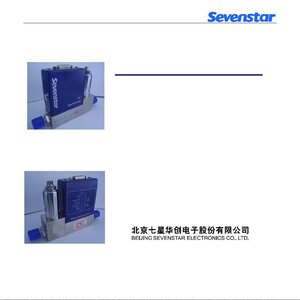
D07 - 7B 型 质量流量控制器
D07-7BM 型 质 量 流 量 计
使 用 手 册
版本 2011 . 12
Page 2

目 录
1. 使用须知…………………………….. 1 6.2.1 开机预热 …………………..…… 15
2. 用途和特点………………………… 1 6.2.2 检查和调整零点 ………………… 15
3. 主要技术指标……………………… 3 6.2.3 通气工作 ………………………… 15
4. 结构和工作原理…………………… 4 6.2.4 关机 ……………………………… 15
4.1 结构………………………………… 4 7. 注意事项 …………………………… 15
4.2 工作原理…………………………… 5 7.1 禁用流量介质 ……………………… 15
5. 安装和接线 ……………………… 7 7.2 使用腐蚀性气体问题 ……………… 15
5.1 外形及安装尺寸…………………… 7 7.3 阀口密封问题 ……………………… 16
5.2 气路接头形式……………………… 8 7.4 阀控操作注意 ……………………… 16
5.3 连接电缆插头……………………… 9 7.5 安装位置问题 ……………………… 16
5.4 与计算机或外部信号的连接……… 11 7.6 注意工作压差 ………………………
5.5 调零和外调零……………………… 12 7.7 标定和不同气体的换算 …………… 17
6. 使用方法和操作步骤 ……………… 13 7.8 D07-7B,7BM 标准订单填写格式…… 18
6.1 质量流量控制器的操作…………… 13 8. 故障判断和处理 …………………… 21
6.1.1 开机操作………………………… 13 9. 保证、保修与服务…………………… 23
6.1.2 清洗功能………………………… 14 9.1 产品保证和保修..…………………… 23
6.1.3 显示仪与计算机连接的操作…… 14 9.2 保修对使用的要求..………………… 23
6.1.4 直接与计算机连接的操作……… 14 9.3 服务..………………………………… 23
6.1.5 阀控功能………………………… 15 10. 附录 ………………………………… 24
6.1.6 关机操作………………………… 15 10.1 气体质量流量转换系数 …………… 24
6.2 质量流量计的操作 ………………. 15 10.2 转换系数使用说明 ………………… 26
16
MASS FLOW CONTROLLER & MASS FLOW METER
Page 3

质量流量控制器和质量流量计
使 用 手 册
1. 使用须知
尊敬的用户,感谢您购买本公司生产的 D07 系列质量流量控制器/质量流量计产品。本
手册详细叙述了正确、安全使用该系列产品的必要事项。
产品使用者,请务必认真参阅本手册并理解后使用,在使用过程中,请注意带有
志的文字及注意事项中包含的所有内容。
对于未按照使用手册使用造成的财产损失或人身伤害,本公司有权不承担责任。
本手册对您安装、维护及故障维修时,必不可少,请妥善留存保管。
2. 用途和特点
质量流量计(Mass Flow Meter 缩写为 MFM) 用于对气体的质量流量进行精密测量;质
量流量控制器 (Mass Flow Controller 缩写为 MFC) 用于对气体的质量流量进行精密测量
和控制。它们在半导体和集成电路工业、特种材料学科、化学工业、石油工业、医药、环
保和真空等多种领域的科研和生产中有着重要的应用。其典型的应用场合包括: 电子工艺
设备, 如扩散、氧化、外延、CVD、等离子刻蚀、溅射、离子注入; 以及镀膜设备、光纤
熔炼、微反应装置、混气配气系统、毛细管测量、气相色谱仪及其它分析仪器。
D07 系列质量流量控制器和质量流量计具有精度高、重复性好、响应速度快、软启动、
稳定可靠、工作压力范围宽等特点(可以在高压或真空条件下工作), 其操作使用方便, 可任
意位置安装, 并便于与计算机连接实现自动控制。
D07 系列质量流量控制器和质量流量计一般与 D08 系列流量显示仪等产品配套使用,
控制器与显示仪之间用专用电缆连接(如图 1 所示)。
标
第 1 页 共 26 页
Page 4
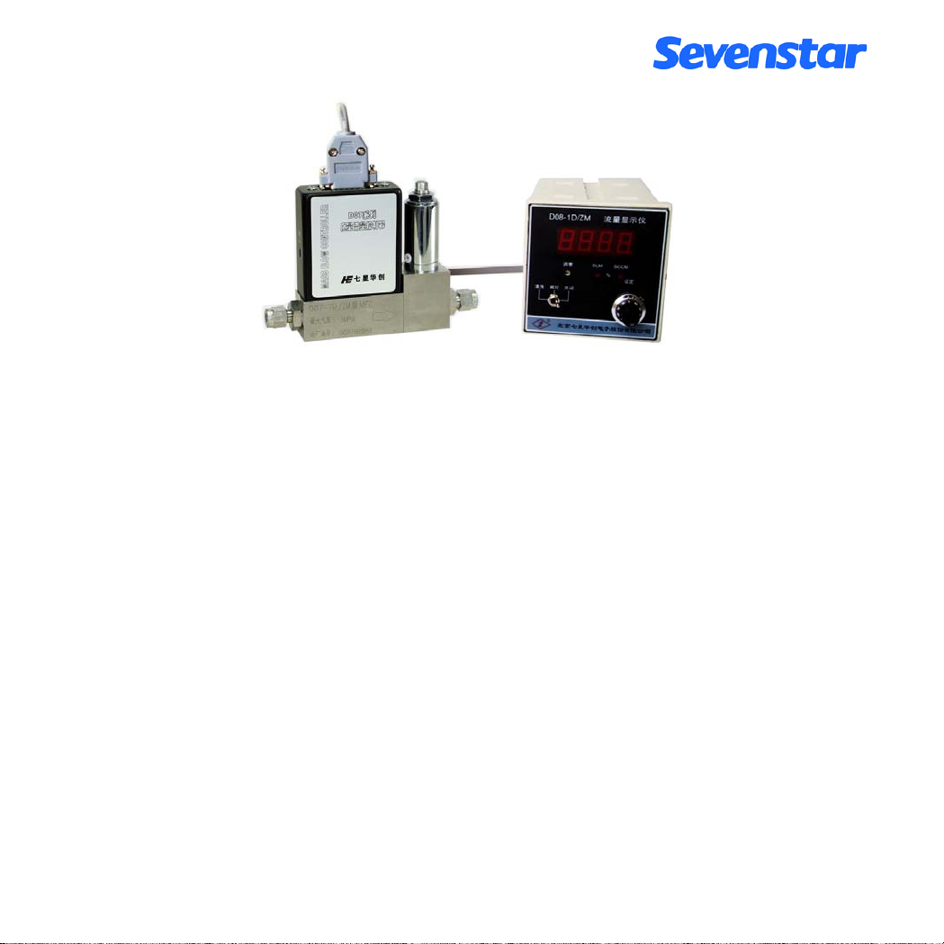
图 1.质量流量控制器与流量显示仪配套使用
第 2 页 共 26 页
Page 5

3. 主要技术指标
表 1. D07-7B 型 MFC 性能指标
编号 项 目 D07-7B 型
1 流量规格 ( 0~5,10,20,30,50,100,200,300,500) SCCM
( 0~1,2,3,5,10) SLM
2 准确度 ±1.5 % F.S
3 线性 ±1 % F.S
4 重复精度 ±0.2 %F.S
5 响应时间
6 工作压差范围 (0.1 ~ 0.5) MPa
7 耐压 3 MPa
8 工作环境温度 5 ℃ ~ 45 ℃
9 输入输出信号
(输入阻抗大于 100K, 输出电流不大于 3mA)
10 电源
11 外形尺寸 见图 4
12 重量 1.1 kg
电特性: 10 sec
气特性: ≤ 4 sec
0 V ~ +5.00 V
+15 V 50 mA
-15V 200 mA
注意
质量流量计和质量流量控制器出厂通常用氮气(N
:
)标定。
2
质量流量的单位规定为: SCCM (标准毫升/分);
SLM (标准升/分)
标准状态规定为: 温度 --- 273.15K ( 0℃ );
气压 — 101325 Pa (760mm Hg)
F.S. (Full Scale): 满量程值
第 3 页 共 26 页
Page 6
表 2. D07-7BM 型 MFM 性能指标
编号 项 目 D07-7BM 型
1 流量规格 ( 0~5,10,20,30,50,100,200,300,500) SCCM
( 0~1,2,3,5,10) SLM
2 准确度 ±1.5 % F.S
3 线性 ±1 % F.S
4 重复精度 ±0.2 %F.S
5 响应时间 10 sec
6 气压降 <0.01 MPa
7 耐压 3 MPa
8 工作环境温度 5 ℃ ~ 45 ℃
9 输出信号
10 电源
11 外形尺寸 见图 5
12 重量 0.92 kg
(输入阻抗大于 100K, 输出电流不大于 3mA)
0 V ~ +5.00 V
+15 V 50 mA
-15 V 50 mA
各型号产品的主要技术指标见表 1 和表 2。其中 7BM 型是 7B 型的流量测量部分,流
量计量部分的技术指标相同。
4. 结构和工作原理
4.1 结构
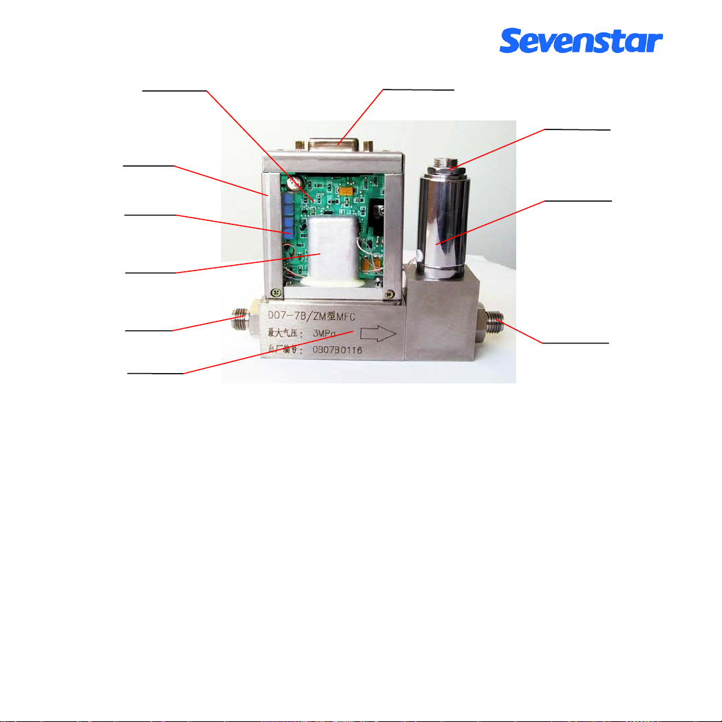
质量流量计由流量传感器, 分流器通道和流量放大电路等部件组成;在质量流量计的
基础上,再加上调节阀门和 PID 控制电路就构成了质量流量控制器。7B 型质量流量控制
器, 打开外罩后的结构如图 2 所示。
第 4 页 共 26 页
Page 7
传
电路印制板
D 型插座
锁紧螺母
支架
调零电位器
电磁调节阀
感器
进气接头
出气接头
流量通道
图 2. 7B 型质量流量控制器结构图
7BM 型流量计与 7B 型控制器相比,在结构上的不同点,就是少了电磁调节阀,其它
部分基本相同。
4.2 工作原理
流量传感器采用毛细管传热温差量热法原理测量气体的质量流量(无需温度压力补偿)。
将传感器加热电桥测得的流量信号送入放大器放大, 放大后的流量检测电压与设定电压进
行比较, 再将差值信号放大后去控制调节阀门,闭环控制流过通道的流量使之与设定的流量
相等。分流器决定主通道的流量。与之配套的 D08 系列流量显示仪上设置有稳压电源, 3 位
半数字电压表, 设定电位器, 外设、内设转换和三位阀控开关等。本控制器与流量显示仪连
接后的工作原理如图 3 所示。
第 5 页 共 26 页
Page 8
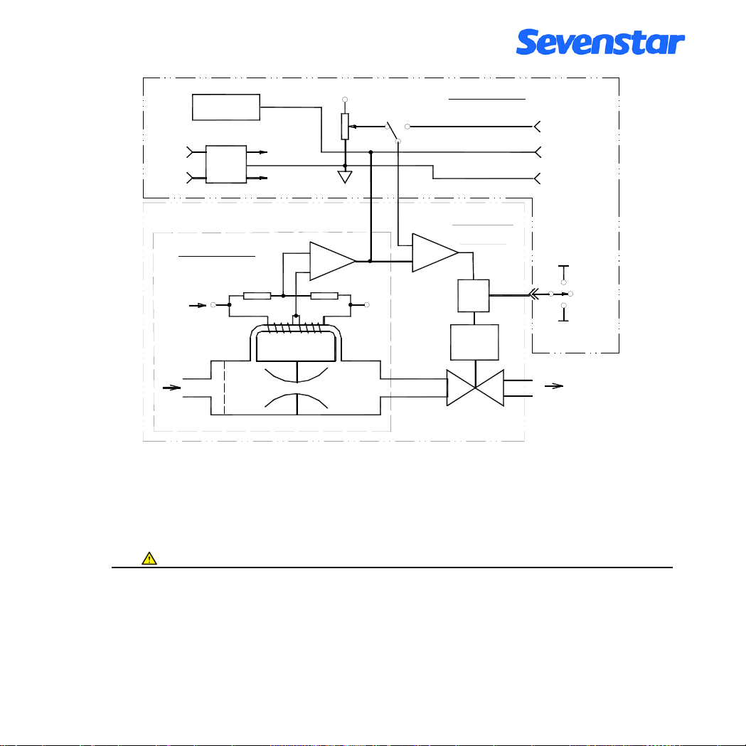
~220V
100.0
流量显示
电源
+15V
0V
-15V
+5.00V
设定
内
外
流量显示仪
(0 ~ +5.00V)
(0 ~ +5.00V )
COM
设 定
流量检测
0 电 平
比较器
质量流量
控制器
阀控
驱动
调节阀
+15V
关闭
清洗
-15V
出口
质量流量计
放大器
I
传感器
out
set
入口
分流器通道
图 3. 质量流量控制器原理
控制器输出的流量检测电压与流过通道的质量流量成正比, 满量程(F.S)流量检测输出
电压为+5V。质量流量控制器的流量控制范围是(2~100)%F.S, 流量分辨率是 0.1%F.S。
注意
:
当质量流量控制器的“阀控”线置于“清洗”位时,也可以当质量流量计使用。在做
流量计使用时,流量检测电压的输出值最大可能达+10V 以上,不过要注意,当流量超过满
量程值(+5V)后,流量检测电压与通过的实际流量不成线性对应关系。清洗时,流量显示
不准确,还可能出现流量增大显示反而减小的异常现象,但并不会对流量计本身造成损伤。
第 6 页 共 26 页
Page 9
控制操作一般在流量显示仪上进行。当设定开关打到“内”设时, 由设定电位器控制流
量; 当打到“外”设时, 由用户提供的(0~+5)V 电压控制流量。
在显示面板上还设置有三位阀门控制开关, 当置“关闭”位时, 阀门关闭; 当置“清洗”
位时,阀门开到最大,以便气路清洗,或作为流量计使用;当置于“阀控”时,自动控制流量。
5. 安装和接线
5.1 外形及安装尺寸:
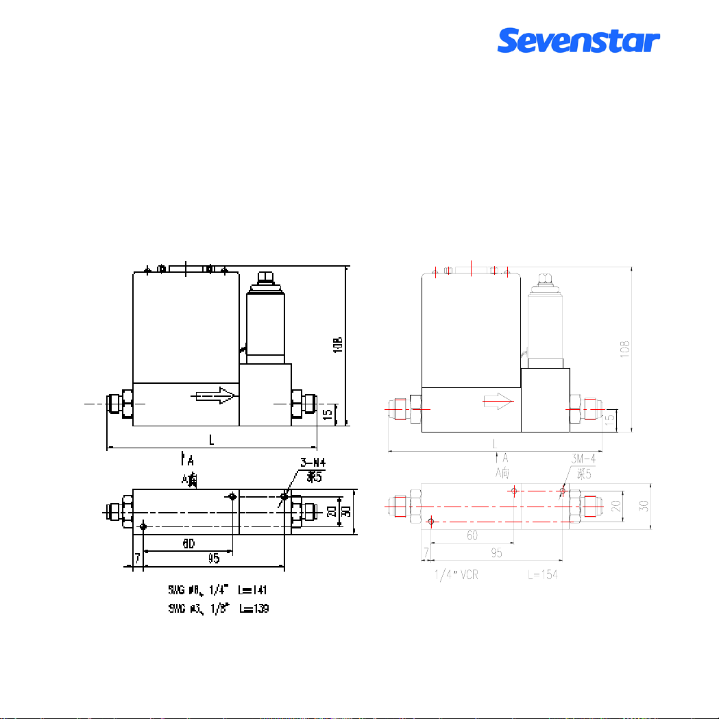
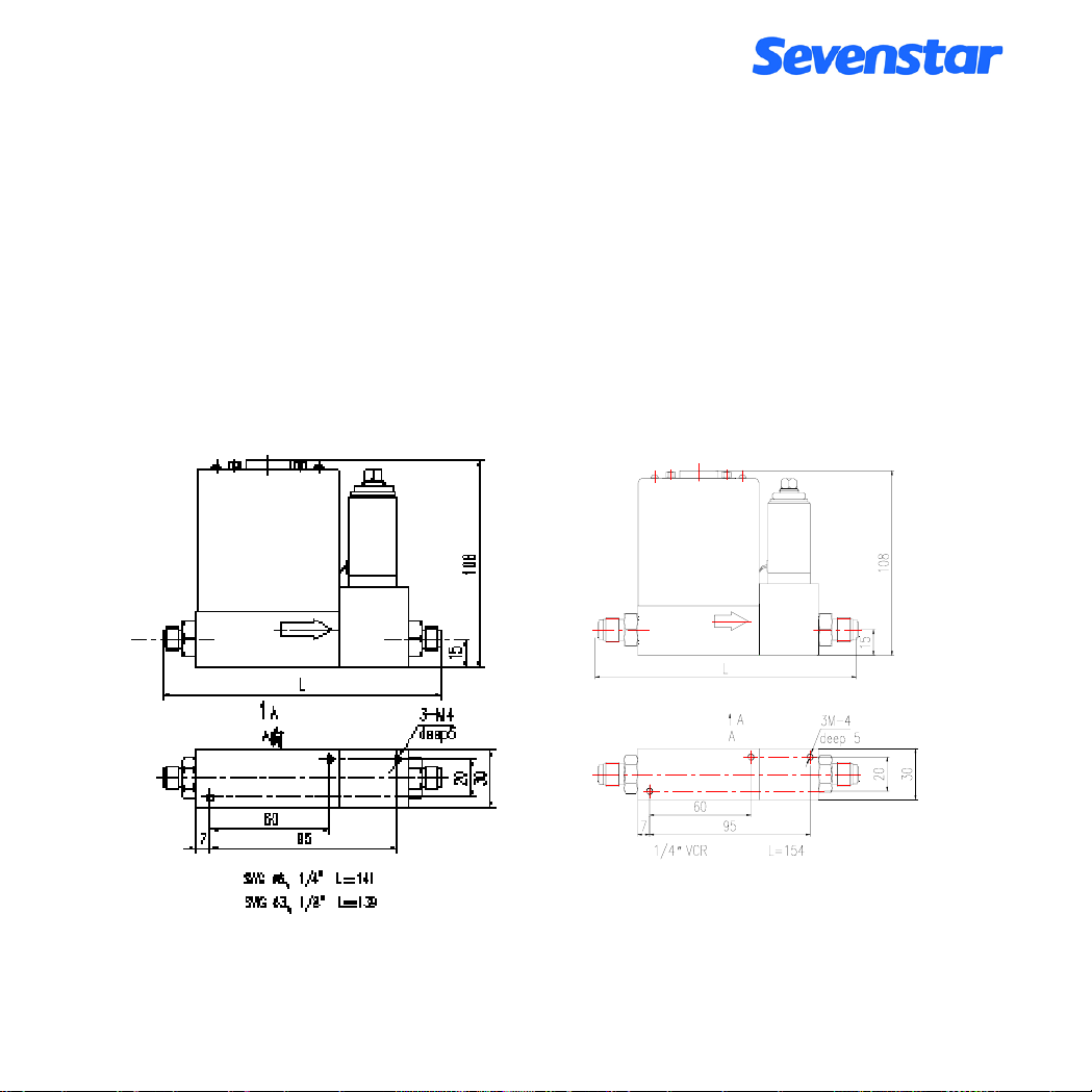
7B、7BM 各型号产品的外形和安装尺寸如图 4、图 5 所示。
图 4. D07-7B 型 MFC 外形图
第 7 页 共 26 页
Page 10
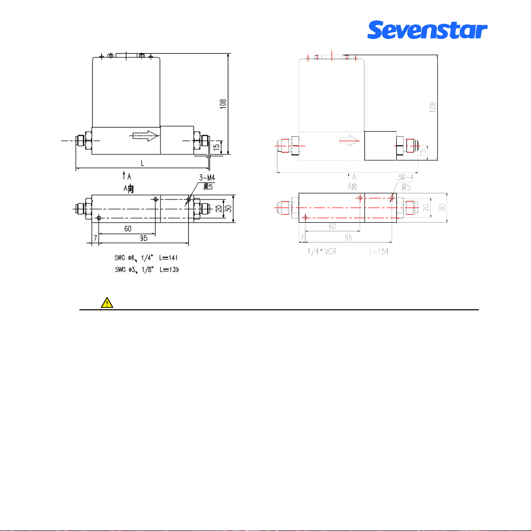
图 5. D07-7BM 型 MFM 外形图
注意 :
图中的高度 108mm 是不加电缆插头的高度,加上插头后的高度要再增加 50mm 左右。
5.2 气路接头形式
采用标准双卡套 (Swagelok)接头和 VCR 接头, 可提供 5 种尺寸接管外径的接头类型:
a. Swagelokφ3 mm ;
b. Swagelokφ6 mm ;
c. Swagelok
d. VCR
e. Swagelok
一般用金属管将质量流量控制器与气路相连接,在要求不高的情况下也可以用尼龙管
或其它较硬的弹性塑料管。双卡套接头的连接方法, 如图 6 所示。注意流量计通道上的箭
头指示的方向是气流方向, 进出气方向不能接反。
1/4" (英制);
1/4"(英制);
1/8" (英制)。
第 8 页 共 26 页
Page 11
接管
螺母
后卡套
前卡套
图 6. 双卡套接头安装示意图
注意 :
按图 6 所示安装接管时,在装上前卡套、后卡套、螺母后,先用手将螺母与接头拧紧,
再用扳手拧紧(国外进口的 Swagelok 接头要求用扳手旋转 1.25 圈拧紧
意应该使用双扳手操作,用一只扳手卡住接头不动,用另一只扳手旋转螺母。特别是在拆卸
接管时必须使用双扳手操作,否则会引起接头松动,影响密封。
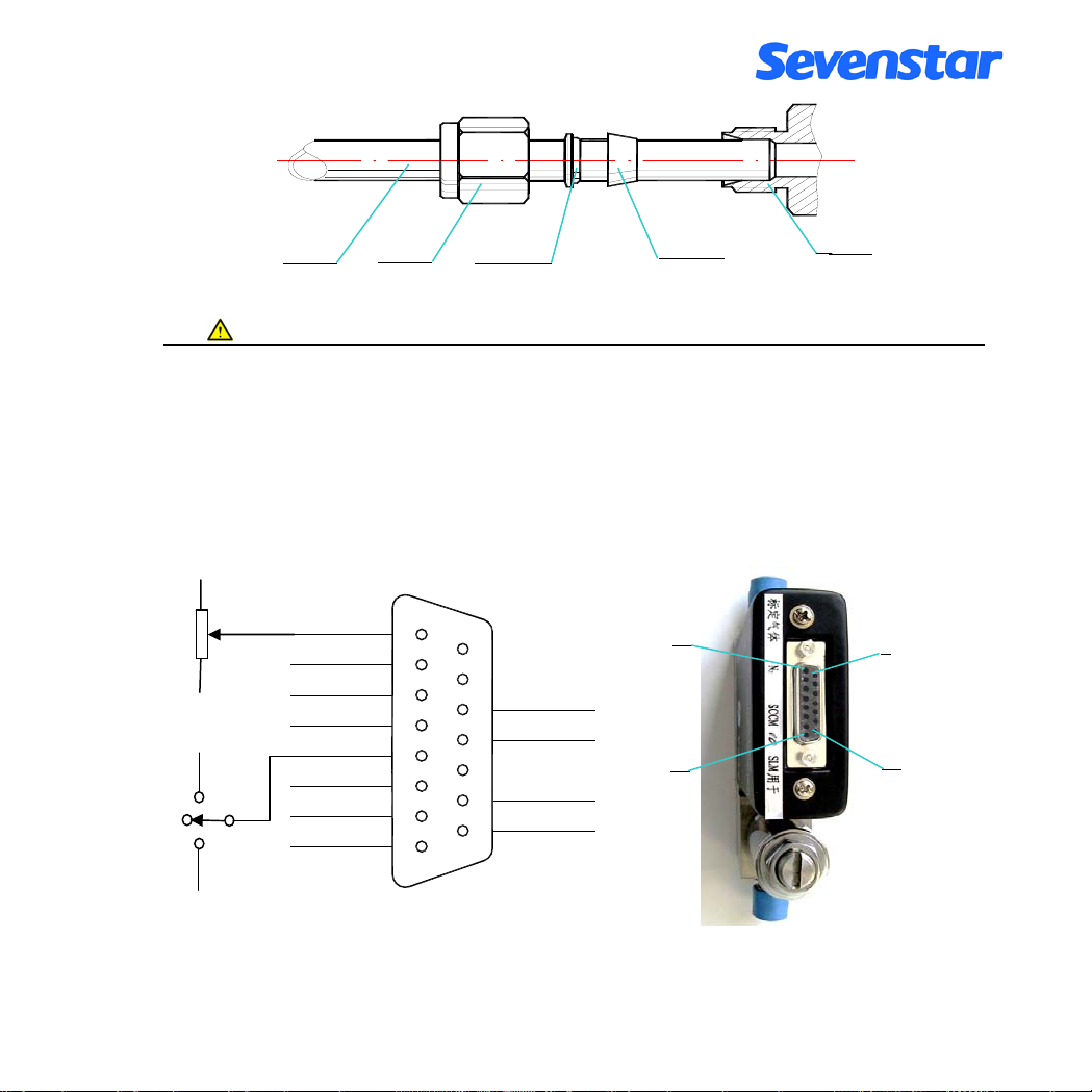
5.3 连接电缆插头
+15V
-15V
+15V
关闭
清洗
-15V
外调零
电源地
(0~+5V)
设定
阀控
信号地
流量检测
地
1
2
3
4
5
6
7
8
9
10
11
12
13
14
15
-15V
-15V
公共地
+15V
1
8
图 7. 7B 型控制器 D 型插座和接线图
接头
),以保证不漏气。注
9
15
第 9 页 共 26 页
Page 12
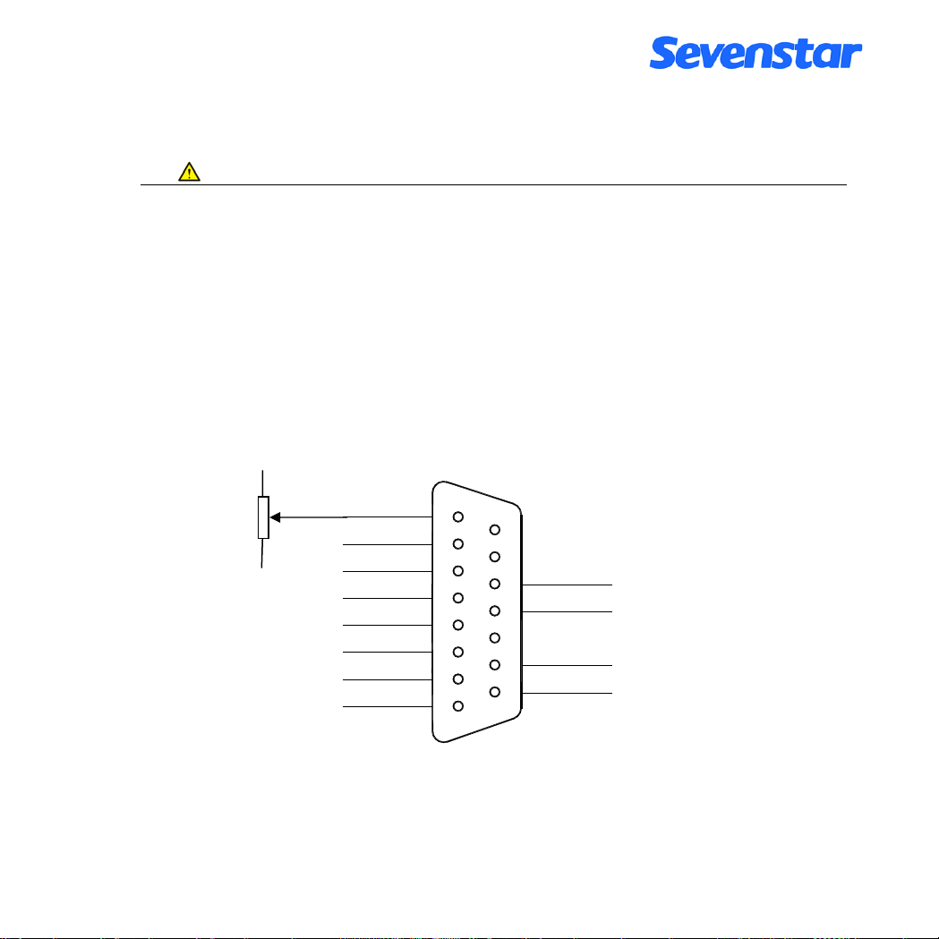
质量流量控制器通过专用电缆与配套流量显示仪连接后, 即可通电通气工作。
注意
:
D07-7B 型是 D07-7A 型产品的的升级换代型,7B 型采用了贴片元件,和国际标准的 D 型
插头。与 7A 型对照,插头引线功能的位置相同,但起始编号的方向相反。7B 型可以直接替
换 7A 型产品,7A 型原有的电缆可以直接插在 7B 型插座上工作,只是锁紧装置不一样,当然,
在替换时,通常应该连插头(或电缆)一起更换。
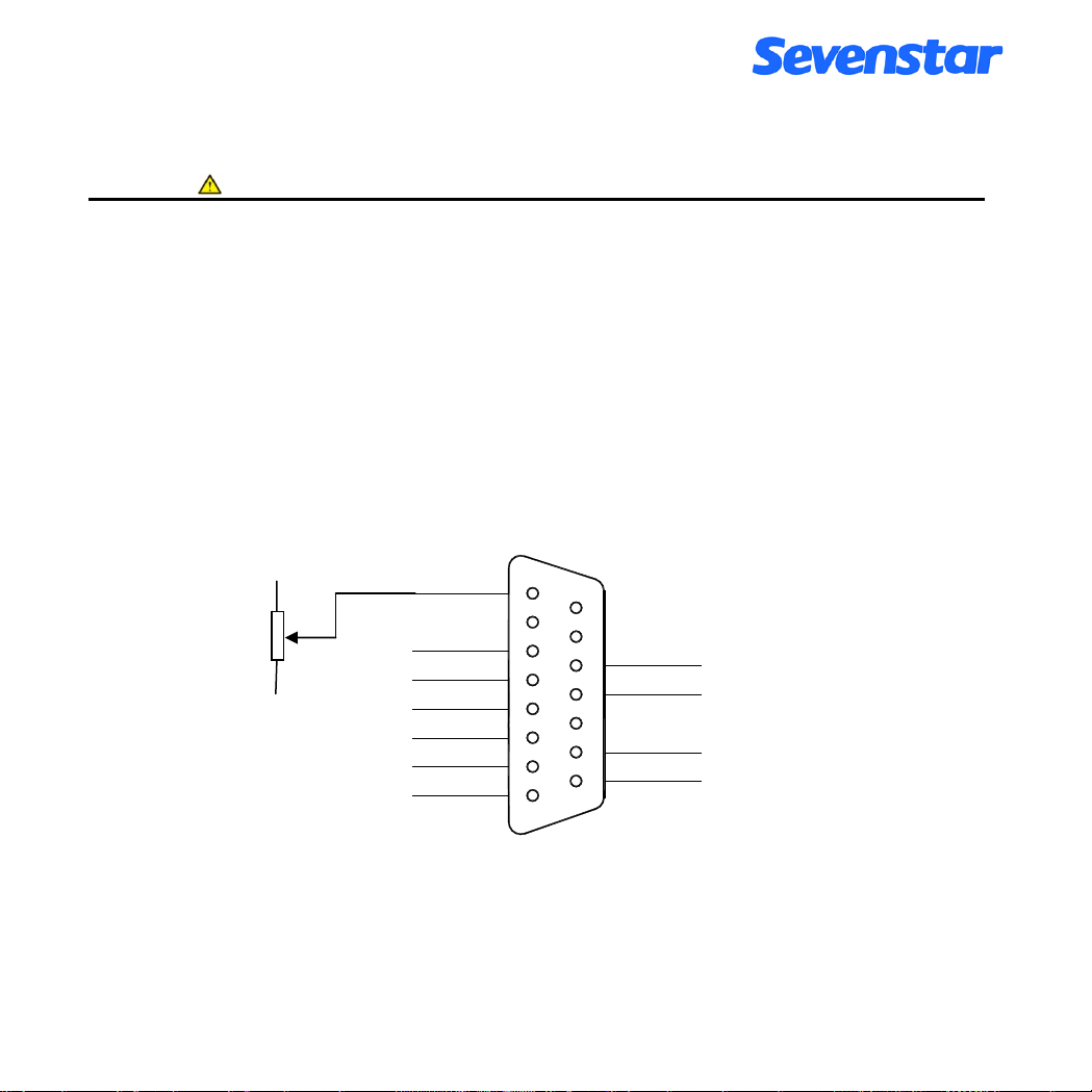
7BM 型质量流量计插座的接线见图 8, 7BM 型与 7B 的插座型号完全相同,只是在流
量计插件的接线中与控制器插件相比,少了“阀控”和“设定”两根线。
+15V
-15V
外调零
电源地
信号地
流量检测
地
1
2
3
4
5
6
7
8
10
11
12
13
14
15
9
-15V
-15V
公共地
+15V
图 8. 7BM 型流量计 D 型插座接线图
第 10 页 共 26 页
Page 13
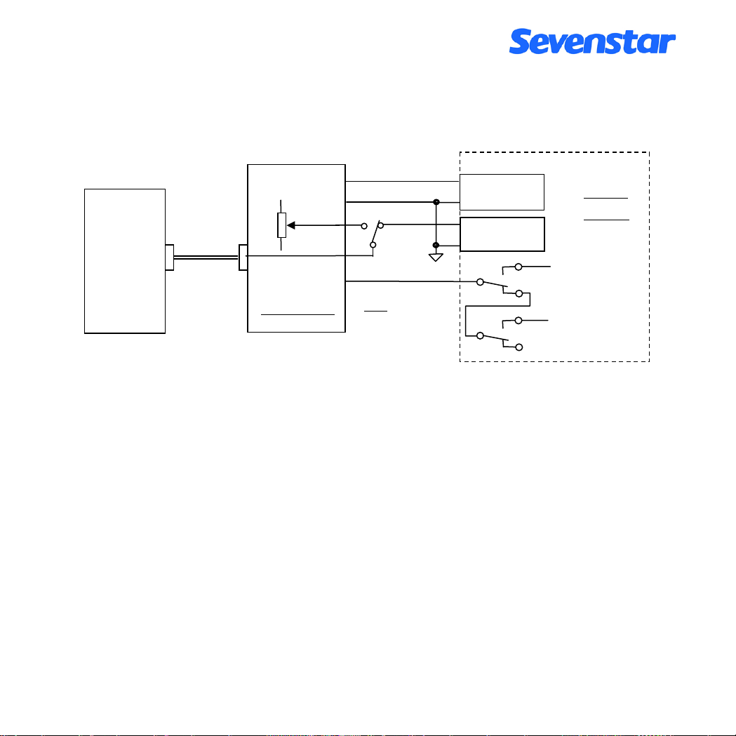
5.4 与计算机或外部信号的连接
a. 通过流量显示仪与计算机(或其它外部信号)的连接方法, 见图 9。
质量流量
质量流量计
控制器
或
连接电缆
流量检测
信号地
内设
设定
阀控
流量显示仪
( 注意: 质量流量计
无阀控线和设定线 )
外设
A/D 转换输入
信号地
D/A 转换输出
信号地
计算机
或 PLC
+15V
关闭
-15V
清洗
图 9. 通过流量显示仪与计算机的连接
若用户要检测流量输出信号(0V~+5V)时, 将线引至显示仪外控信号插座的“流量检测”
和“信号地”(0 电平)线上即可,也可直接与计算机的模数(A/D)转换器连接,+5.00V 输出
电压对应 MFC 满量程额定流量值。注意,流量检测输出电流不大于 3mA。
若流量设定使用外部信号,应将设定选择开关打至“外”,并从显示仪上的外控信号插
座送入 0V~+5.00V 外设电压。若用户外接电位器设定,可以用一个 3.3K 左右的多圈电位
器, 将两端连接到外控信号插座“+5.00V”和“信号地”上即可。也可直接与计算机的数模
(D/A)转换器连接,实现自动控制。注意流量设定的输入阻抗大于 100KΩ。
如果还需要计算机实现“阀控”线的关闭和清洗功能,可以用两个继电器的(两组)
转换触点来实现。一个继电器控制“关闭”,一个继电器控制“清洗”,两个继电器都不动
作则为自动控制。注意不能因两个继电器同时动作时引起电源短路, 推荐使用图 10 的继电
器触点接线方式。
第 11 页 共 26 页
Page 14
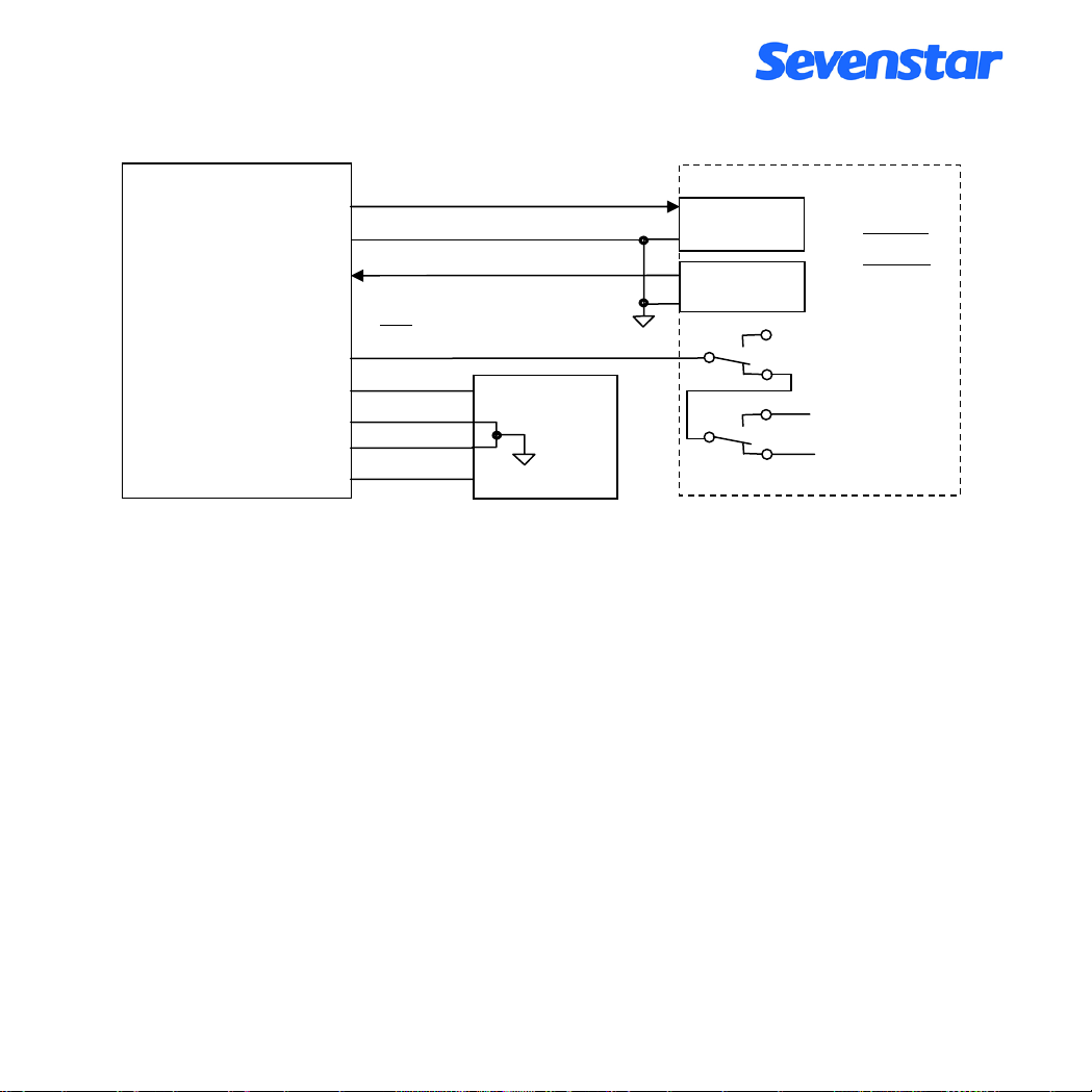
b. 流量计直接与计算机连接的接线方法,见图 10。
质量流量
质量流量计
流量检测
信号地
控制器
或
公共地
电源地
0~+5V
0~+5.00V
设定
( 注意: 质量流量计无阀控线和设定线 )
阀控
+15V
-15V
+15V
-15V
COM
电源
A/D 转换输入
信号地
D/A 转换输出
信号地
-15V
+15V
计算机
或 PLC
阀控
清洗
关闭
图 10. 直接与计算机连接的接线方法
如果是 MFC/MFM 直接与计算机连接,需要用户自己提供±15V 电源(要求电源抗干
扰能力要强);将“设定”线接计算机 D/A 输出;将“流量检测”线接计算机 A/D 输入端;
“信号地”线接外部信号参考地;小电流地线“公共地”和大电流地线“电源地”,分别引
线,一起接在±15V 电源的公共端。
如果需要计算机实现“阀控”、“关闭”和“清洗”功能,推荐使用图 10 的阀控线与继
电器触点之间的接线方式。
5.5 调零和外调零
首次使用或工作一段时间后,若发现零点偏移, 可以调整。能通过外罩上进气口侧面的
调零孔调整,也可揭开外罩调整。调整电位器位置示意如图 11 所示。注意:调零时流量管路
不能通气(或将阀门关闭);必须在开机预热 15 分钟以上,待流量计零点稳定以后进行。
通常除调零电位器外,其它电位器不得轻易调整。
第 12 页 共 26 页
Page 15
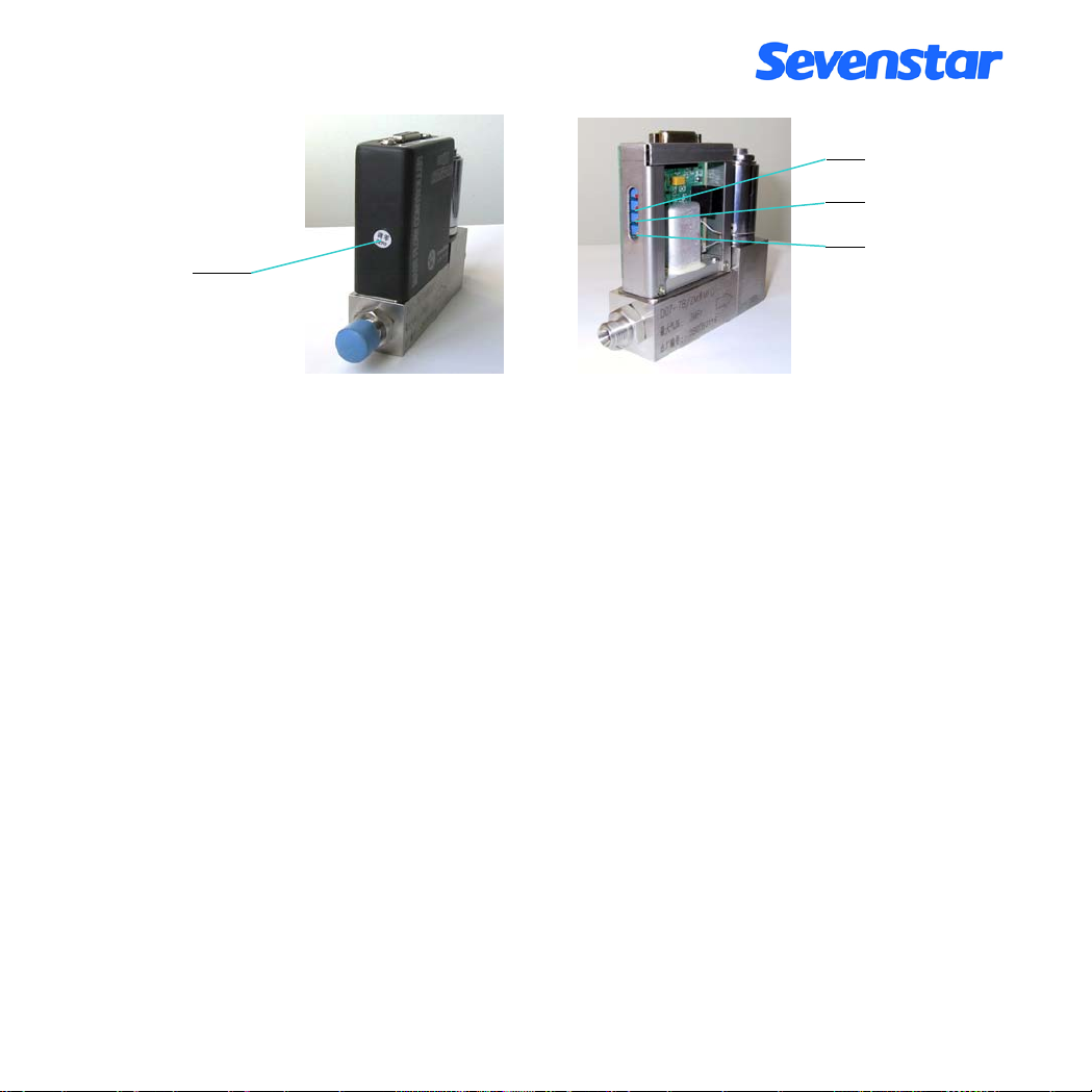
线性
调零孔
增益
调零
图 11. 7B 和 7BM 型调节电位器位置图
本机还设计有外调零功能,当控制器与我厂新生产的(带外调零功能的)D08 系列流量
显示仪配套工作时,也可以通过显示仪面板上的调零电位器调零。但要注意,外调零的调
节范围比较小,若遇到较大的零点偏移,还需要调节控制器上的调零电位器,才能解决。
6. 使用方法和操作步骤(结合 D08 系列流量显示仪)
6.1 质量流量控制器的操作
6.1.1 开机操作
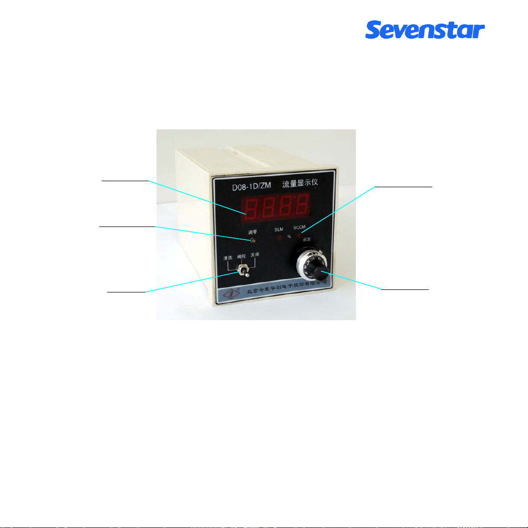
使用时主要操作在流量显示仪上进行(参见图 12)。阀门控制开关及流量设定电位器在前
面板上,流量设定的内部或外部信号选择开关一般在后面板上。当设定选择开关打到“内”
时,用设定电位器设定流量,打到“外”时,由外部信号设定流量(参见流量显示仪的使
用说明书)。
a. 阀开关处于“阀控”位时,先开气后开电源,则气体流量软启动经过约 20 秒钟达到原设定
值的 5%以内。一般应先将阀关闭,不通气,通电预热 15 分钟,待零点稳定以后再正式工
作。如果零点偏差较大,参见 5.5 条, 在不通气的情况下,可以通过调零电位器调零。
b. 阀开关处于“关闭”位, 在开电源预热并开气后,再将阀开关置至“阀控”位, 则流量经过几
秒钟后达到设定流量的 2%以内。这是推荐操作方法。
c. 阀开关处于“清洗”位,在开电源、开气后,则管路流量达到最大值,起到吹洗气路的作
用。
第 13 页 共 26 页
Page 16
d. 阀开关处于“阀控”位,并且设定不为零时,如果先开电源,后开气,则流量将会有一个大
过冲,然后迅速稳定至设定值。这种操作方法应当避免。
e. 先开电源、将阀开关置到“关闭”位,将设定值调到零,再开气,待预热至零点稳定后,
再转“阀控”位,然后将设定流量调至需要值, 则实际流量跟踪设定值而改变,无过冲。这
是最佳操作方法。
流量显示窗
流量单位指示
外调零电位器
阀控开关
设定电位器
图 12. 流量显示仪操作面板
6.1.2 清洗功能
欲用气体吹洗管路,可将阀开关置为“清洗”位, 清洗时的流量可达该控制器额定满量
程流量的几倍至几十倍。如果不通气,则根据需要可以抽真空以排除 MFC 内部及其上游残
存气体。然后将阀关闭,再开气,并转到“阀控”位工作。
6.1.3 显示仪与计算机连接的操作
参照图 1 和图 9,先将显示仪上的设定开关打到“外设”位,将阀控开关置于“阀控”
位,再启动计算机程序进行工作。
6.1.4 直接与计算机连接的操作。
参照图 1 和图 10,在流量计预热稳定以后,即可启动程序进行工作。
第 14 页 共 26 页
Page 17

6.1.5 阀控功能
当阀开关置于阀“控位”时, 用户也可通过外控信号插座上的“阀控”线控制阀门, (参
照图 3 和图 9),当阀控线接+15V 时,阀门关闭;当阀控线接-15V 时,阀门开到最大,处
于清洗状态;当阀控线悬空时,阀门处于自动控制状态。
6.1.6 关机操作
切断电源后,流量自动截止。最好先关气(将阀控开关置于“关闭”位和关闭气路中
的截止阀), 后断电源。
6.2 质量流量计的操作
6.2.1 开机预热: 使用前,先接通电源预热 15 分钟。
6.2.2 检查和调整零点
预热后, 检查流量计的零点(特别是在首次使用时), 参见 5.5 条, 在不通气的情况下,
可以通过调零电位器调零。
6.2.3 通气工作: 待零点稳定后, 即可通气工作。注意观察气体流量, 最好不要超过满量程使用。
6.2.4 关机: 切断电源, 即停止流量计的测量工作, 不影响通道流过的气体流量。
7. 注意事项
7.1 禁用流量介质
使用气体必须净化,切忌粉尘、液体和油污。必要时,须在气路中加装过滤器等。如果
流量计出口接有液体源瓶, 应在流量计出口加装单向阀, 防止液体回流损坏流量计。
7.2 使用腐蚀性气体问题
流量计通道采用的材料为: 00Cr
17Ni14Mo2
(相当于 316L 不锈钢) ,氟橡胶等耐蚀材料。
在用户系统无水汽、低泄漏、勤清洗、使用得当的条件下, 可以用于控制一般的腐蚀性气体。
使用氨气的用户应在定货时声明。7B、7BM 型流量计产品不能用于有机溶剂蒸汽(如丙酮
等)和 BCl
、BBr3等强腐蚀性气体。阀口的密封材料通常为氟橡胶或耐氨橡胶,对于 7B
3
第 15 页 共 26 页
Page 18

型质量流量控制器也可以选用聚四氟乙烯;当选用四氟乙烯时,阀口容易出现漏气,阀口
密封的漏气率小于满量程流量的 2%;对于使用特殊腐蚀性气体,所有密封材料都要作相应
改变。
注意
:
对于使用腐蚀性或有毒、易燃气体的产品,通气使用前应严格保证并检验安装和联接
的气密性;如需从系统上卸下,应在断开气路前,使用干燥的对人体无害的常规气体(如
氮气、空气)或惰性气体对产品进行彻底的清洗。如没有清洗,可能会引起火灾、爆炸、
中毒等意外事故,将导致人员伤亡。
7.3 阀口密封问题
质量流量控制器的电磁阀是调节阀, 不是截止阀, 不能当截止阀使用, 用户应另配截
止阀。特别是用户如果使用腐蚀性气体, 通常应该在质量流量控制器进出气口各加一个截
止阀, 以保证工作安全。长期工作后, 如果控制器阀口的漏气率在 2%F.S 以内, 是属于正常
情况。如果漏气大于满量程的 2%, 则应进行维修。
7.4 阀控操作注意
在操作阀门进行“清洗”后,不得直接转至“阀控”位工作,必须先将阀门置至“关闭”
位,然后再转至“阀控”位工作。
7.5 安装位置问题
本流量计安装时最好保持安装面水平。用户订货时应注明实际安装位置,我公司根据用
户的安装位置进行标定后出厂。如果用户的实际安装位置与产品出厂时的标定位置不一致
时,产品可能出现零点偏移,此时可调整零点后再工作。
7.6 注意工作压差
对于质量流量控制器要特别注意工作介质的气压,应注意使控制器进出气口两端的工作
压差保持在指标范围之内。特别是在高压下工作时,气压差过大,流量将无法关闭或调小。
在使用大流量的质量流量控制器时,要注意适当加粗管道和减小气源内阻,若工作压差小
第 16 页 共 26 页
Page 19

于要求值,有可能流量达不到满量程值。
7.7 标定和不同气体的换算
本流量计出厂通常用氮气(N
)标定。如果要求用使用气体标定, 需要在订货时与销售
2
人员特别申明。
用氮气标定的流量计用户使用其它气体时, 可以通过附录 10.1 的转换系数进行换算,
算出被使用气体的流量。将质量流量控制器显示出的流量读数,与某使用气体的转换系数
相乘,即得该被测气体在标准状态下的质量流量。
例如:一个出厂标定为 100 SCCM(N
) 的 MFC,通甲烷气体时显示的流量为 86 SCCM,
2
从附录 10.1 查得甲烷的转换系数为 0.719,则甲烷的实际流量为 86×0.719 即 61.8 SCCM。
如果用户使用混合气体,可以通过附录 10.2 介绍的方法, 计算出混合气体的转换系数。
第 17 页 共 26 页
Page 20

7.8 D07-7B、7BM 标准订单的填写格式
D07-[t] [g,g,g] [r,r,r,r] [f,f] [s] [m] [d]
[t] –型号
- [7B ] 质量流量控制器
- [7BM] 质量流量计
[g,g,g] – 使用气体
依照标准SEMI52-0302
例如:
-[ 013 ] N
-[ 007 ] H
-[ 000 ] 混合气体详见[d]
[r,r,r,r] –满量程流量
- [ 005C] 5SCCM
- [ 010C] 10SCCM
- [ 020C] 20SCCM
- [ 030C] 30SCCM
- [ 050C] 50SCCM
- [ 100C] 100SCCM
- [ 200C] 200SCCM
- [ 300C] 300SCCM
- [ 500C] 500SCCM
- [ 001L] 1SLM
- [ 002L] 2SLM
- [ 003L] 3SLM
- [ 005L] 5SLM
- [ 010L] 10SLM
- [ 000C] 特殊量程详见
2
2
[d]
第 18 页 共 26 页
Page 21

D07-[t] [g,g,g] [r,r,r,r] [f,f] [s] [m] [d]
[f,f] – 进出气接头
-[AA ] Swagelokφ3mm
-[GG] Swagelokφ6mm
-[BB ] Swagelok 1/8"
-[CC ]
Swagelok 1/4"
-[MM] VCR 1/4"
-[XX ]
特殊接头详见[d]
[s] – 密封材料
-[ V ] 氟橡胶
-[ N ] 氯丁橡胶(耐氨橡胶)
[m] – 安装位置
-[ H ] 水平安装
-[ E ] 平躺安装
-[ U ] 进气口向上垂直安装
-[ D ] 进气口向下垂直安装
[d] – 其它说明
-[ - ] 出厂默认:
外罩及标签文字:中文
工作压差范围:D07-7B:(0.1 ~ 0.5) MPa (14.5~72.5 psid)
耐压:3 MPa (435.1 psig)
标定温度:(22±2)℃
-[ S ] 特殊要求:
例如:外罩及标签文字:英文;特殊量程:9SLM;混合气体要注明比例: N
工作压差范围:(0.05 ~ 0.3) MPa;标定温度:40℃及其它特殊要求等。
D07-7BM:<0.01MPa (1.5psid)
2 (60%) + CO2(40%);
第 19 页 共 26 页
Page 22

举例:
以D07-7B007001LCCNUS为例:
D07-7B 007 001L CC N U S
型号:D07-7B MFC
使用气体:
H2
满量程流量:1SLM
进出气接头:
Swagelok 1/4"
密封材料:
氯丁橡胶(耐氨橡胶)
安装位置:
进气口向上垂直安装
特殊要求:
如 英文,工作压差(0.05~ 0.3) MPa,特殊接头(附图纸),
特殊标定温度40℃等要求逐一填写。
第 20 页 共 26 页
Page 23
8. 故障判断和处理
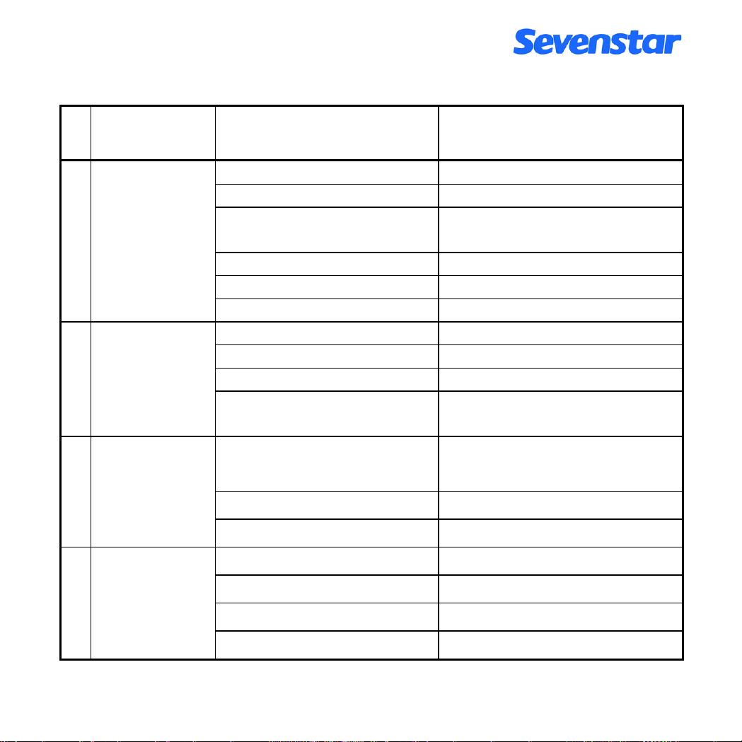
表 3. 故障判断和处理一览表
序
号
故 障 现 象 故 障 可 能 原 因 处 理 方 法
开机后, 无气流
1
流过
开机不通气的情
2
况下, 流量检
测不正常
在阀门关闭的情
3
况下,仍有较大的
流量流过
1.1 气源未开, 气路不通 接通气源, 开通气路
1.2 阀控开关关闭 将阀开关置于"阀控"位或"清洗"位
1.3 无设定信号
检查设定电位器和"内外"设定开关
的状态等
1.4 过滤器堵塞 *更换过滤器
1.5 调节阀故障 检查阀线包是否断, *清洗调节阀
1.6 电路故障 *维修电路
2.1 零点偏差 调整调零电位器
2.2 电源故障 *检查±15V 电源等
2.3 传感器故障 *更换传感器
2.4 运算放大器或其它电路故
障
*更换运放, 维修电路
3.1 入口气压过高,进出气口之
适当降低输入气压,减小气压差
间的压差超过额定值
3.2 阀门污染 *清洗阀门,更换密封件
3.3 调节阀故障 *重新调整调节阀
流量显示不能达
4
到满量程值
4.1 气压降低于额定值 提高入口气压
4.2 通道堵塞 *清洗 MFC 通道
4.3 设定电压低于 5.00V *检查设定电压
4.4 其它电路故障 *维修电路
第 21 页 共 26 页
Page 24

续表 3. 故障判断和处理一览表
序
号
故 障 现 象 故 障 可 能 原 因 处 理 方 法
5.1 气源压强太低或不稳 提高气源气压, 稳定气源压强
气流控制不稳定,有
5
较大的波动
5.2 气源内阻过大
5.3 电路或调节阀故障 *维修调整
6.1 供电系统的地线和零线
使用高频源时流量
6
控制器受干扰
连接或机壳接地有问题
6.2 信号参考端连接问题 检查信号连接线
6.3 空间干扰 适当屏蔽,远离干扰源, 选用屏蔽线
7.1 显示器量程或单位与控
制器不匹配
实际流量与显示流
7
量不一致
7.2 控制器通道被污染,引起
流量精度发生偏差
7.3 流量计零点有较大漂移,
不稳定
设定为零时仍有流
8
量流过
通道有很大气流流
9
过, 而输出无流量
8.1 调节阀漏气 *维修调节阀
8.2 流量计零点偏负 将流量计零点调为零或偏正
9.1 传感器堵塞
显示
9.2 电路故障 *维修电路
不通气时, 发现零
10
点不稳, 或零点长
10.1 传感器故障 *更换传感器
时间慢漂移
注意 :
标*号的项目必须由专业维修人员进行修理。
降低气源内阻 (大流量时要注意开
大阀门, 加粗管道, 以至并联气瓶,
提高气源供气能力)
检查接地系统, 注意一点接地
*重调显示器
*对控制器进行清洗标定
*更换传感器, 维修电路
*维修更换传感器
气源有粉尘, 应在通道前加装过
滤器。若使用硅烷等特殊气体,应注
意管路的密封性和气源干燥
第 22 页 共 26 页
Page 25

9. 保证、保修与服务
9.1 产品保证和保修
9.1.1 本公司生产的MFC/MFM产品在出货两年以内,如果用户按照说明书要求使用,并且产品没
有遭受物理损害、污染、改装或翻新,我们保证产品的材料、加工和性能的质量,若有问题,
免费维修。
9.1.2 用户收到货物后,有责任检查及核对货物,并通过传真、电话或电子邮件的方式及时通知
本公司销售部有关收货情况。
9.1.3 保修期内,产品必须由本公司或授权的服务中心修理,否则,产品的保修是无效的。
9.1.4 在两年保修期以内,维修是免费的。如果保修期过了,在维修前将会通知用户需要更换的
部件及维修费用。维修后,在90天以内对修理的部分进行保修,保修件包括易损件 (四氟或
密封圈等)。
9.1.5 用户使用过有毒、有污染或腐蚀性气体的产品, 如果没有出示清除污染及净化处理的证明,
本公司将不负责修理或保修。
9.2 保修对使用的要求
a.气体必须洁净且没有颗粒物, 没有液体, 这就要求在MFC/MFM的上游气路中安装<30μm
的过滤器。
b.输入的气体压力必须符合产品的耐压标准, 不能超过该产品要求的最大压力。
c.产品的使用气体必须与用户订货选择的密封材料相适应, 用户有责任按照可用的安全规章
使用每种气体。不正确的使用产品会使保修无效,由于不正确的使用所导致的损害不能
归咎于本公司。
d.对电子线路的要求:必须小心按规定连接系统的接线, 不正确的接线会导致产品内部电路
板的永久损坏。若自备MFC电源, 需要电压波动小于5mV的高抗干扰稳压电源。
e.气路的连接:必须仔细的安装密封管件, 保证所有的密封管件经过单独检查并且没有划痕。
f.禁止自行拆开MFC/MFM。如果自行拆卸造成损坏,则本公司承诺的保修无效。
9.3 服务
本公司的产品工程师将会帮助您解决关于操作、标定、机电连接、工作条件要求、气体
转换等方面的问题。我们提供技术支持与维护, 提供产品的使用培训。
请您访问mfc.sevenstar.com.cn
找到有关的产品资讯和离您最近的维修及服务中心。
第 23 页 共 26 页
Page 26
10. 附录
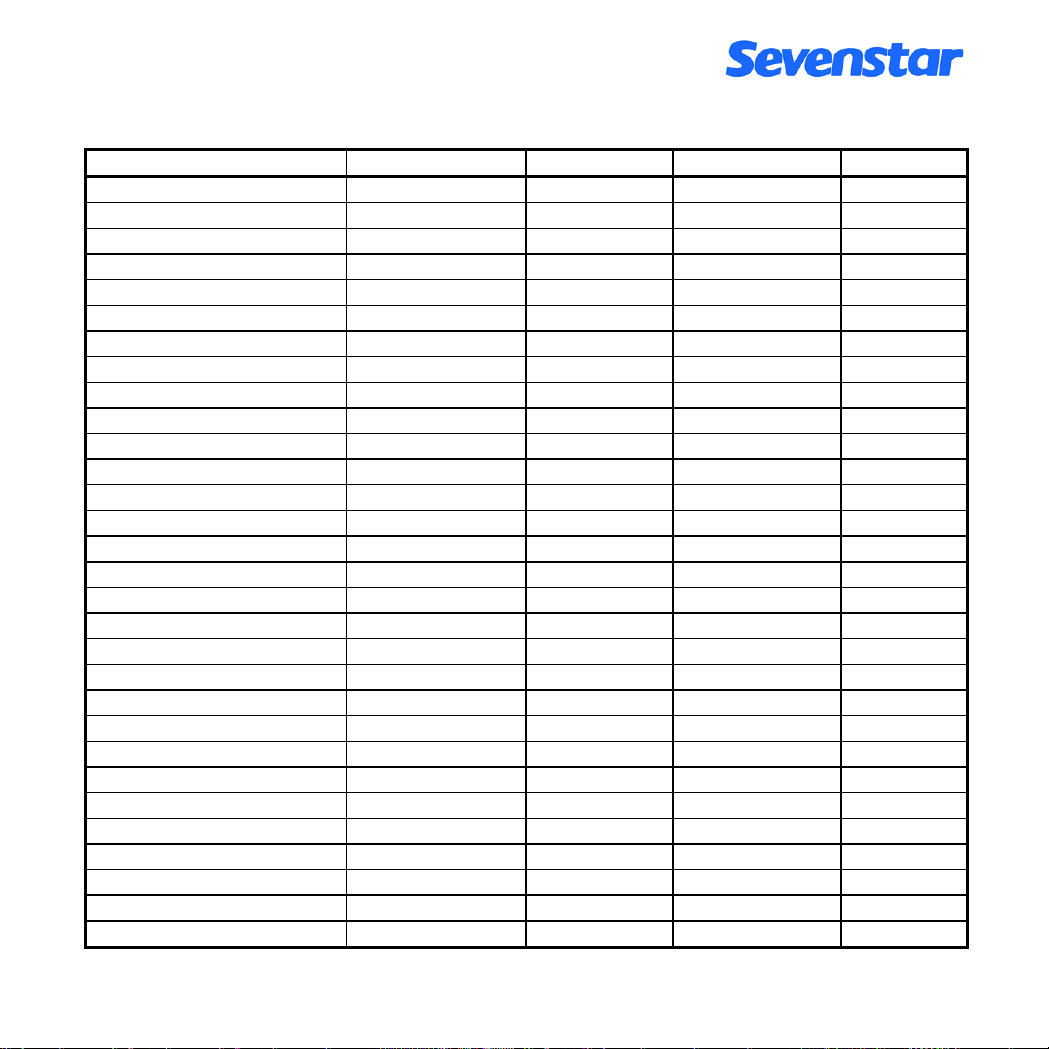
10.1 气体质量流量转换系数: 表 5. 气体质量流量转换系数表
Air
Ar
AsH3
BBr3
BCl3
BF3
B2H6
CCl4
CF4
CH4
C2H2
C2H4
C2H6
C3H4
C3H6
C3H8
C4H6
C4H8
C4H10
C5H12
CH3OH
C2H6O
C2H3Cl3
CO
CO2
C2N2
Cl2
D2
F2
GeCl4
气 体 代号
空气
氩气
砷烷
三溴化硼
三氯化硼
三氟化硼
硼烷
四氯化碳
四氟化碳
甲烷
乙炔
乙烯
乙烷
丙炔
丙烯
丙烷
丁炔
丁烯
丁烷
戊烷
甲醇
乙醇
三氯乙烷
一氧化碳
二氧化碳
氰气
氯气
氘气
氟气
四氯化锗
(SEMIE52-0302) 比热(卡/克℃) 密度(克/升 0℃) 转换系数
008
004
035
079
070
048
058
101
063
028
042
038
054
068
069
089
093
104
111
240
176
136
112
009
025
059
019
014
018
113
0.2400 1.2930 1.006
0.1250 1.7837 1.415
0.1168 3.4780 0.673
0.0647 11.1800 0.378
0.1217 5.2270 0.430
0.1779 3.0250 0.508
0.5020 1.2350 0.441
0.1297 6.8600 0.307
0.1659 3.9636 0.420
0.5318 0.7150 0.719
0.4049 1.1620 0.581
0.3658 1.2510 0.598
0.4241 1.3420 0.481
0.3633 1.7870 0.421
0.3659 1.8770 0.398
0.3990 1.9670 0.348
0.3515 2.4130 0.322
0.3723 2.5030 0.294
0.4130 2.5930 0.255
0.3916 3.2190 0.217
0.3277 1.4300 0.584
0.3398 2.0550 0.392
0.1654 5.9500 0.278
0.2488 1.2500 1.000
0.2017 1.9640 0.737
0.2608 2.3220 0.452
0.1145 3.1630 0.858
1.7325 0.1798 0.998
0.1970 1.6950 0.931
0.1072 9.5650 0.267
第 24 页 共 26 页
Page 27
GeH4
H2
HBr
HCl
HF
HI
H2S
He
Kr
N2
Ne
NH3
NO
NO2
N2O
O2
PCl3
PH3
PF5
POCl3
SiCl4
SiF4
SiH4
SiH2Cl2
SiHCl3
SF6
SO2
TiCl4
WF6
Xe
气 体 代号
锗烷
氢气
溴化氢
氯化氢
氟化氢
碘化氢
硫化氢
氦气
氪气
氮气
氖气
氨气
一氧化氮
二氧化氮
一氧化二氮
氧气
三氯化磷
磷烷
五氟化磷
三氯氧磷
四氯化硅
四氟化硅
硅烷
二氯氢硅
三氯氢硅
六氟化硫
二氧化硫
四氯化钛
六氟化钨
氙气
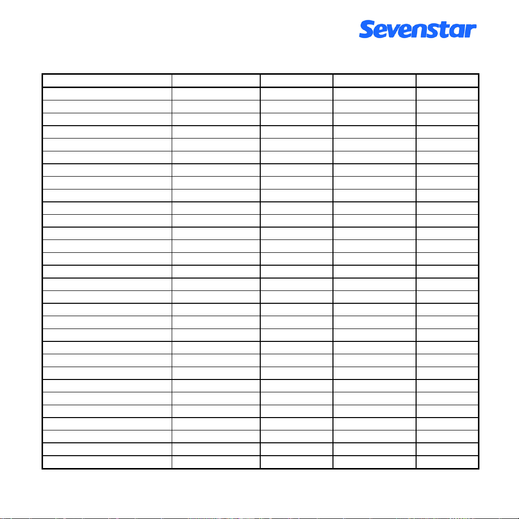
续表 5. 气体质量流量转换系数表
(SEMIE52-0302) 比热(卡/克℃) 密度(克/升 0℃) 转换系数
043
007
010
011
012
017
022
001
005
013
002
029
016
026
027
015
193
031
143
102
108
088
039
067
147
110
032
114
121
006
0.1405 3.4180 0.569
3.4224 0.0899 1.010
0.0861 3.6100 1.000
0.1911 1.6270 1.000
0.3482 0.8930 1.000
0.0545 5.7070 0.999
0.2278 1.5200 0.844
1.2418 0.1786 1.415
0.0593 3.7390 1.415
0.2486 1.2500 1.000
0.2464 0.9000 1.415
0.5005 0.7600 0.719
0.2378 1.3390 0.976
0.1923 2.0520 0.741
0.2098 1.9640 0.709
0.2196 1.4270 0.992
0.1247 6.1270 0.358
0.2610 1.5170 0.691
0.1611 5.6200 0.302
0.1324 6.8450 0.302
0.1270 7.5847 0.284
0.1692 4.6430 0.348
0.3189 1.4330 0.599
0.1472 4.5060 0.412
0.1332 6.0430 0.340
0.1588 6.5160 0.264
0.1489 2.8580 0.687
0.1572 8.4650 0.206
0.0956 13.2900 0.215
0.0379 5.8580 1.415
第 25 页 共 26 页
Page 28

10.2 转换系数使用说明
质量流量控制器、质量流量计出厂时一般用 N
标定,实际使用中如果是其它气体,必
2
要时可进行读数修正,方法是以流量显示仪显示的流量乘以流量转换系数。如是单组份气
体,其转换系数可在我厂产品技术说明书中查得;如是多组份气体(假定由 n 种气体组成),
请按下列公式计算其转换系数 C:
基本公式: C=0.3106 N /ρ(Cp)
其中:
ρ——为气体在标准状态下的密度
CP——为气体的定压比热
N ——为气体分子构成系数(与该气体分子构成的组份有关, 见下表)
气体分子构成系数表:
气体分子构成 举 例 N 取 值
单原子分子 Ar He 1.01
双原子分子 CO N2 1.00
三原子分子 CO2 NO2 0.94
多原子分子 NH3 C4H8 0.88
对于混合气体: N =N
1
(ω
1/ωT
)+N
2
(ω
) + ··· + Nn (ω
2/ωT
n/ωT
)
导出公式:
0.3106 [N
1
(ω
1/ωT
)+N
(ω
2
) + ··· + Nn (ω
2/ωT
n/ωT
)]
C = ————————————————————————
ρ1Cp1 (ω1/ωT )+ ρ2Cp2 (ω2/ωT )+ ··· + ρnCpn (ωn/ωT)
其中:
ω
ρ
CP
N
ω1 …ωn ——为相应气体的流量
——为混合气体的流量
T
——为相应气体在标准状态下的密度 (数值见气体转换系数表)
1…ρn
…CPn ——为相应气体的定压比热 (数值见气体转换系数表)
1
… Nn ——为相应气体的分子构成系数, 取值见气体分子构成系数表
1
说明:
1)标准状态为:压力—101325Pa (760 mm Hg),温度—273.15K (0 )℃ 。
2)气体质量流量转换系数表中未列出的气体的有关参数,可以向我们咨询。
第 26 页 共 26 页
Page 29

D07 系列
质量流量控制器
北京七星华创电子股份有限公司
质量流量计分公司
(北京七星弗洛尔电子设备制造有限公司制造)
地 址: 北京市朝阳区酒仙桥东路 1号
通讯地址: 北京 741 信箱 3 分箱
邮政编码: 100015
联系电话: +86-10-64362939 64362925
+86-10-64361831—8491/8315
传 真: +86-10-64362923
网 址: http://mfc.sevenstar.com.cn
电子信箱(E-mail): [email protected]
乘车路线: 乘地铁到东直门, 换乘 401路公共汽车,到陈各庄下车或
乘地铁到农业展览馆,换乘 516 路公共汽车,到酒仙桥东路北口下车
上海办事处: 上海闸北区天目西路 547 号联通国际大厦 1916 室(200070)
电 话: +86-21-33030324
传 真: +86-21-63533265
深圳办事处: 深圳市福田区振华路 45 号汽车大厦 B712(518031)
电 话: +86-755-88290258
传 真: +86-755-88294770
*公司承诺不断提升产品品质,保
留在不经通知的情况下对此手册
所含信息进行修改的权力。
*本手册内容,已经严格审校,如
有错误或遗漏,劳请及时告知。
*七星电子 版权所有
Page 30
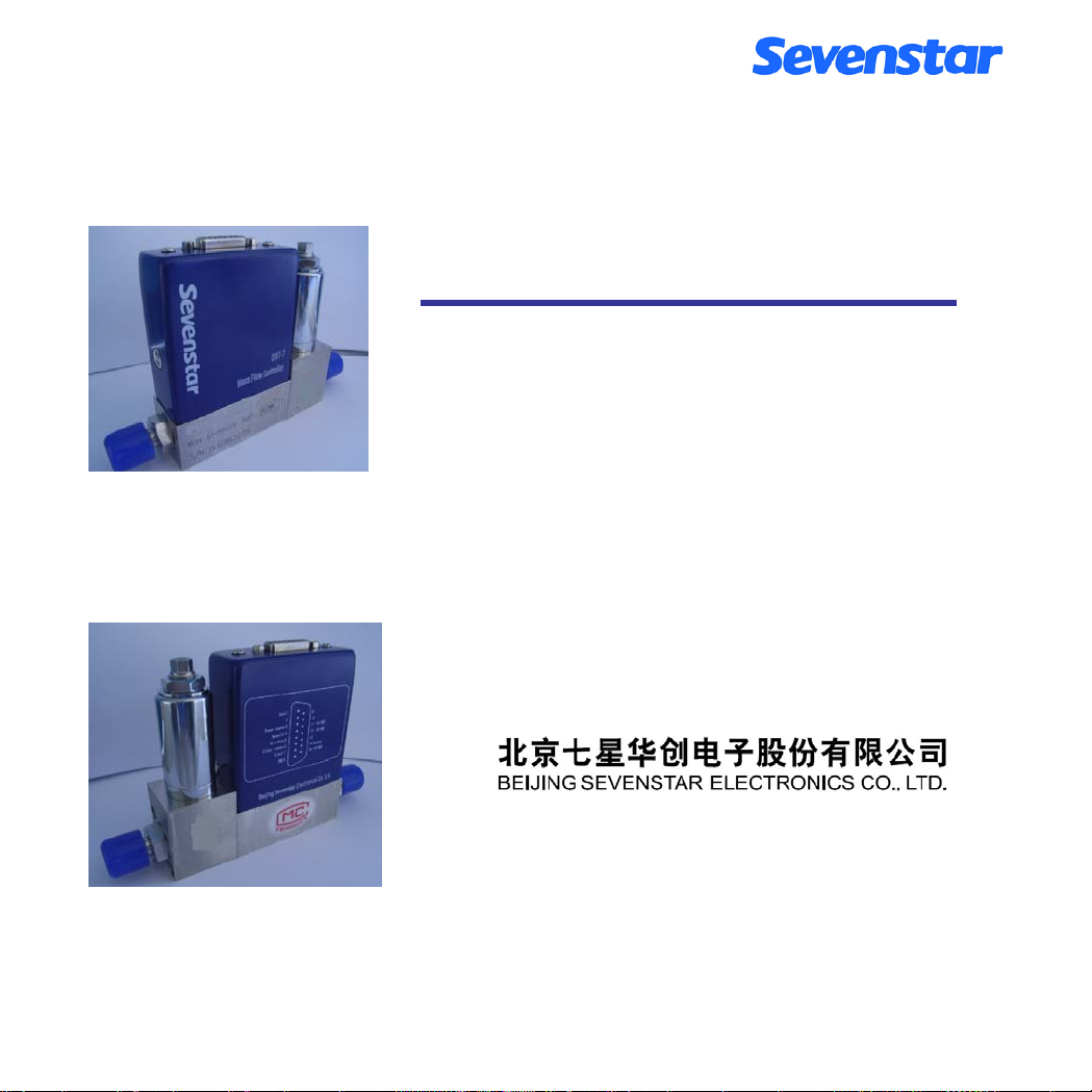
D07-7B / ZM
D07-7BM / ZM
Mass Flow Controller
Mass Flow Meter
INSTRUCTION MANUAL
Version Dec. 2011
Page 31

A NOTE TO OUR CUSTOMERS
Dear customer,
Thank you for purchasing SEVENSTAR D07 series Mass Flow Controller and Mass Flow Meter product.
This user manual is important when installing and doing maintenance. Please keep it carefully.
We strongly recommend that you read this manual thoroughly before you starting to use the product. This user manual
introduces the important issues including the proper and safe use of the products.
And please notice the words and section with the symbol
property caused by loss or personal injury, SEVENSTAR may not be responsible.
If you require any additional information or assistant of Sevenstar D07 series Mass Flow Controller and Mass Flow
Meter, please feel free to contact your local Sevenstar Sales Agent or Sevenstar Customer Service at:
(8610)- 6436 2925.
Yours sincerely,
Sevenstar
. Not in accordance with the user manual for the use of
Page 32

CONTENTS
1. APPLICATION & FEATURES……………. 1 5.2.1 Start Up ………………………………….. 15
2. SPECIFICATION………………………….. 2 5.2.2 Zero Test and Adjustment………………….. 15
3. STRUCTURE & PRINCIPLE……………... 4 5.2.3 Gas Supply…………………………………. 16
3.1 Structure……………………………………. 4 5.2.4 Shut Off……………………………………. 16
3.2 Operation Principle………………………… 4 6. CAUTION…………………………………… 17
4. INSTALLATION …………………………. 7 6.1 Medium Forbidden …………………………... 17
4.1 Receipt and Upacking………………………. 7 6.2 Corrosive Gas ……………………………….. 17
4.2 Dimension………………………………….. 7 6.3 Valves Sealing ……………………………….. 17
4.3 Fittings……………………………………… 8 6.4 Valves operating...……………………………. 17
4.4 Electrical Interfacing ……………………... 9 6.5 Installation Position ………………................. 17
4.5 PC Connections……………………………... 11 6.6 Operation Pressure Resistance………………. 18
4.6 Zero Adjustment……………………………. 12 6.7 Calibration and Conversion………………….. 18
5. OPERATION INSTRUCTIONS………….. 14 6.8 D07-7B, 7BM Ordering Code……………… 19
5.1 MFC Operation…………………………….. 14 7. TROUBLESHOOTING…………………….. 22
5.1.1 Start Up…………………………………… 14 8. WARRANTY & SERVICE………………….. 24
5.1.2 Purge……………………………………… 15 8.1 Product Warranty…………………………….. 24
5.1.3 Readout Box & PC Connections………..... 15 8.2 Specific warranty requirements ……………… 24
5.1.4 PC Connections..…………………………. 15 8.3 Service…………………..…………………… 24
5.1.5 Valves Drive...……………………………. 15 9. APPENDIX…………………………….……. 25
5.1.6 Shut Off Operation……………………….. 15 9.1 Mass Flow Conversion factors……………..... 25
5.2 MFM Operation…………………………….. 15 9.2 Conversion factors Introduction....................... 27
MASS FLOW CONTROLLER & MASS FLOW METER
Page 33
Operating Manual
1. APPLICATION & FEATURES
Mass Flow Meter (MFM) accurately measures mass flow rates, Mass Flow Controller (MFC) accurately
measures and controls mass flow rates despites gas volume fluctuated due to pressure or temperature changes.
Which is widely applied in the fields as: semiconductor and IC fabrication, special materials science, chemical
industry, petrolic industry, pharmaceutical industry, environmental protecting and vacuum system researching,
etc.. The typical applications include: microelectronic process equipment such as diffusion, oxidation, epitaxy,
CVD, plasma etching, sputtering, ion implantation; vacuum deposition equipment, optical fiber melting,
micro-reaction equipment, mixing & matching gas system, capillary flow control system, gas chromatograph and
other analytical instruments.
D07 series MFM & MFC bring the high accuracy, excellent repeatability, quick response, soft-start, better
reliability, wide variety ranges of operation pressure (good operation in high pressure and vacuum situations),
simple convenient operation, flexible installation, possible connecting with PC to carry out automatic control to
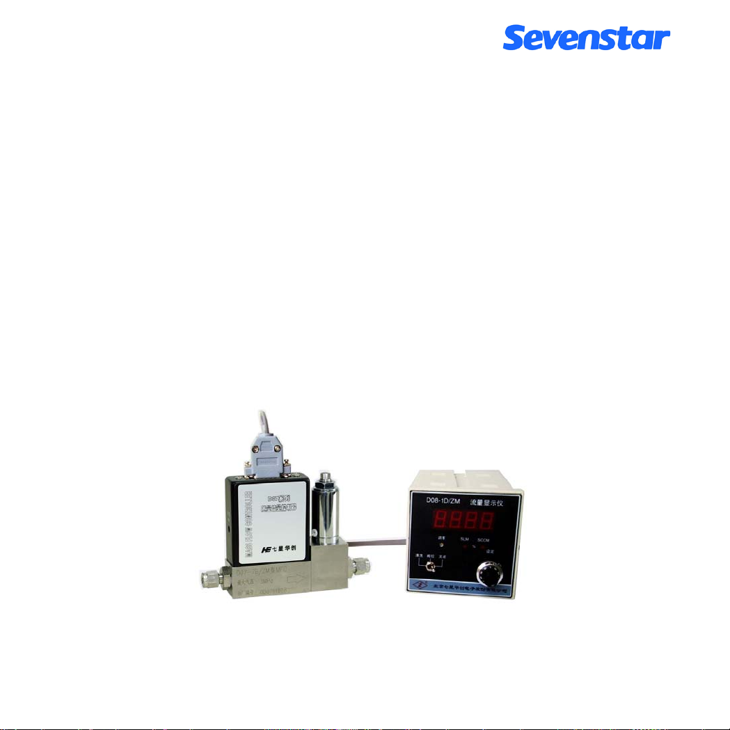
the users’ system. D07 series better is connected together with D08 series Readout Boxes, the cable connection is
showing as following (Figure 1):
Figure 1 MFC and Flow Readout Box
Page 1 of 27
Page 34

2. SPECIFICATION
Table 1.Specifications of D07-7B
No. Item D07-7B
1 Ranges of Flow ( 0~5,10,20,30,50,100,200,300,500) SCCM
2 Accuracy ±1.5 % F.S
3 Linearity ±1 % F.S
4 Repeatability ±0.2 %F.S
Response-Time
5
(0~100%)
6 Operation Pressure (0.1 ~ 0.5) MPa
7 Max Pressure 3 MPa
8 Operation Temperature 5 ~ 45 ℃℃
9 Input/Output Signal
10 Valve N.C.Solenoid
11 Power Supply
12 Dimension
13 Weight 1.1 kg
( 0~1,2,3,5,10) SLM
Electronic characteristic: 10 sec
Gas characteristic: ≤ 4
0 V ~ +5.00 V
(Input resistance value 100K, output current 3mA)
+15 V 50 mA
-15V 200 mA
sec
According to Figure 4
Notes :
MFC/MFM is calibrated by N2 as a standard gas.
Units: SCCM (Standard cubic centimeter/min);
SLM (Standard liter/min)
Standard situation: Temperature 273.15K (0 ºC); Air pressure 101325 Pa (760mm Hg)
F.S: Full Scale
Page 2 of 27
Page 35

Table 2. Specification of D07-7BM Mass Flow Meter
NO. Item D07-7BM
1 Ranges of Flow ( 0~5,10,20,30,50,100,200,300,500) SCCM
( 0~1,2,3,5,10) SLM
2 Accuracy ±1.5 % F.S
3 linearity ±1 % F.S
4 Repeatability ±0.2 %F.S
5 Response-Time 10 sec
6 Differential pressure <0.01 MPa
7 Max pressure 3 MPa
8 Operation temperature 5 ºC ~ 45 ºC
9 Setting/output signal
10 Power supply
11 Dimensions
12 Weight 0.92 kg
(input resistance value 100K, output current 3mA)
0 V ~ +5.00 V
+15 V 50 mA
-15 V 50 mA
According to Figure 5
The main specifications of D07 series could be found in table 1 and table 2. D07-7BM is the measuring part of
D07-7B.
Page 3 of 27
Page 36
3. STRUCTURE & OPERATION PRINCIPLE
3.1 Structure
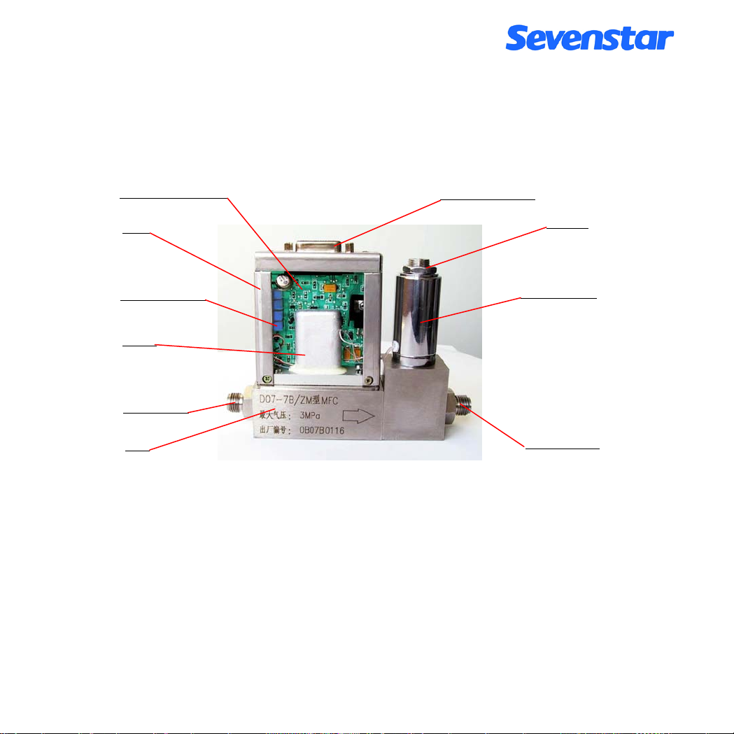
The MFC consists of four basic devices: flow sensor, flow-splitter bypass, control valve and printed circuit
board.
Printed Circuit Board
Stand
Electric Connector
Locknut
Zero Adjustment
Solenoid Valve
Sensor
Inlet-Fittings
Base
Outlet-Fittings
Figure 2. Structure of D07-7B
Structure of D07-7M is basically as same as structure of D07-7A except solenoid valve.
3.2 Operation Principle
The flow sensor that measure the mass flow (it don’t need pressure compensation) is a kind of capillary pipe
temperature difference flow sensor which consists of two dependent resistors winding on the thin-wall capillaries.
As the gas flows through the sensor tube, gas molecules carry heat down the tube from the upstream coil to the
downstream coil, and a temperature difference is produced. The resistance thermometers are parts of a bridge and
amplifier circuit, thus the change in resistance due to the temperature difference results in a 0~5 VDC electric
Page 4 of 27
Page 37
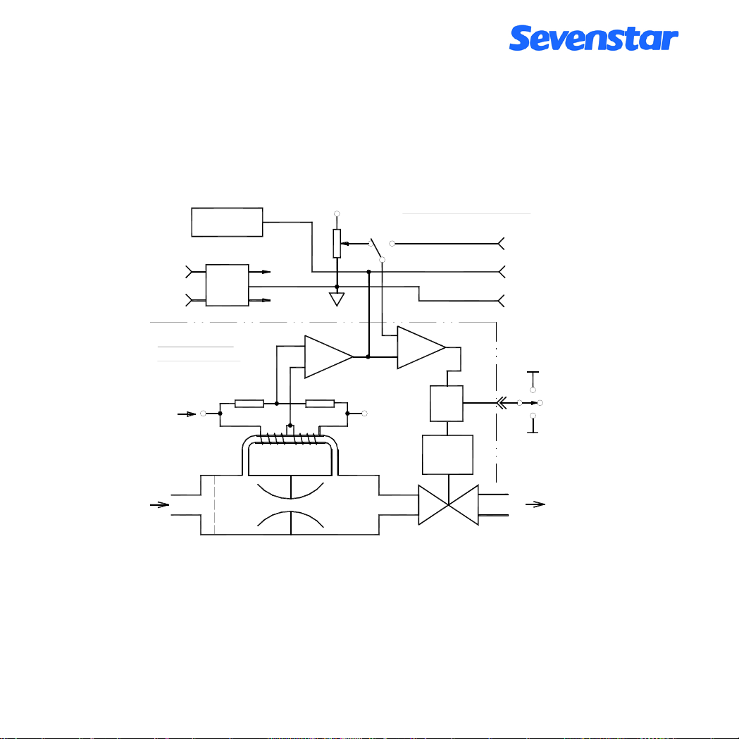
signal which is proportional to the mass flow rate of the gas through the tube. This 0~5 VDC signal is
compared to a set point voltage from a D08 series Flow Readout Box (or other voltage source). From this
comparison, any deviation between set point signal and measured signal are chapleted into a control valve
adjustment until two signals are identical.
D08 series is qualified with power supply, 3-1/2 digital voltage meter, and setting potential meter, inner or out
setting switch and others valve turn-on.
100.0
Readout
~220V
MASS FLOW
CONTROLLER
Power
+15V
Power Com.
-15V
+5.00V
INT
out
Amplifier
FLOW READOUT BOX
SET
(0 ~ +5.00V)
EXT
(0 ~ +5.00V)
set
Comparator
Setpoint
Output
Signal Com.
+15V
OFF
Valve
I
Rd
Ru
Drive
Override
AUTO
PURGE
-15V
Sensor
INLET
Bypass
Valve
OUTLET
Figure3. Principle of MFC
Flow test voltage output from MFC is direct ratio to the flow through the bypass, the full flow output is
corresponding DC 5V, the flow scope is (2~100) %F.S..
Page 5 of 27
Page 38

Attention :
When Valve controller of MFC is posited on PURGE, it can be used as a MFM. When it is used as a
MFM, the flow test voltage can reach beyond +10V, but it is important, if the flow is beyond F.S. (Full
Scale), flow will not have linearity relation with test voltage. When it is purging, output flow will be
incorrect, but it is no damage to MFM itself.
There are three situations on the panel of D08 series Flow Readout box: OFF, PURGE and AUTO. When it is set
to OFF, valve of MFC will shut off; when it is set to PURGE, valve will open to the tip of flow in order to clean
the gas systems; when it is set to AUTO, valve will control the flow rate automatically.
You can control the flow on the panel of the Flow Readout box, when the set point is on the INT, flow rate can be
set by inputting the Flow Readout box a signal from remote devices, When the set point is on the EXT, flow rate
can remotely input the signal of voltage that provided by users from remote devices.
Page 6 of 27
Page 39
4. INSTALLATION & CONNECTION
4.1 Receipt and Upacking
The D07-7B mass flow controller are manfactured under clean room conditions, and has been packed acordingly
upon receipt, after receiving the equipment, please carefully check the outer package for any damage incurred
during the transportation. Check that the delivery is complete and no parts are missing. Since the D07-7B can be
ordered in Several configuration, ensure that the scope of supply is corect. If you think there is a problem plase
contact the forwarder at once, with regard to liability.
4.2 Dimension
Dimensions of D07-7B, D07-7BM are showing as following:
Figure 4. Dimension of D07-7B
Page 7 of 27
Page 40
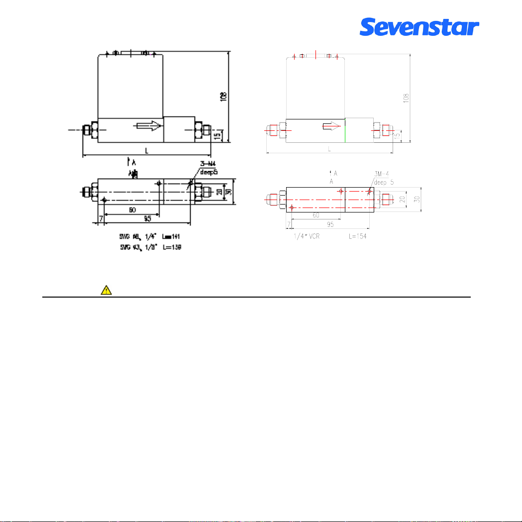
Figure 5. Dimension of D07-7BM/ZM
Attention :
The height of 108mm is the height without electric connector of cable. The height will be added 50mm
more after added the electric connector.
4.3 Fittings
The standard fittings are used Swagelok and VCR, there are five type’s fittings can be provided:
a. Swagelok ф3mm b. Swagelok ф6mm c. Swagelok 1/4" d. Swagelok 1/8" e. VCR 1/4"
Usually, Stainless steel tube was used to connect MFC and Gas System, and other material can be used such as
nylon tube or some flexible metal hose.
Figure 6 is an example of system construction. “ → ” shows the direction of flow, please pay attention for the
flow direction .
Page 8 of 27
Page 41
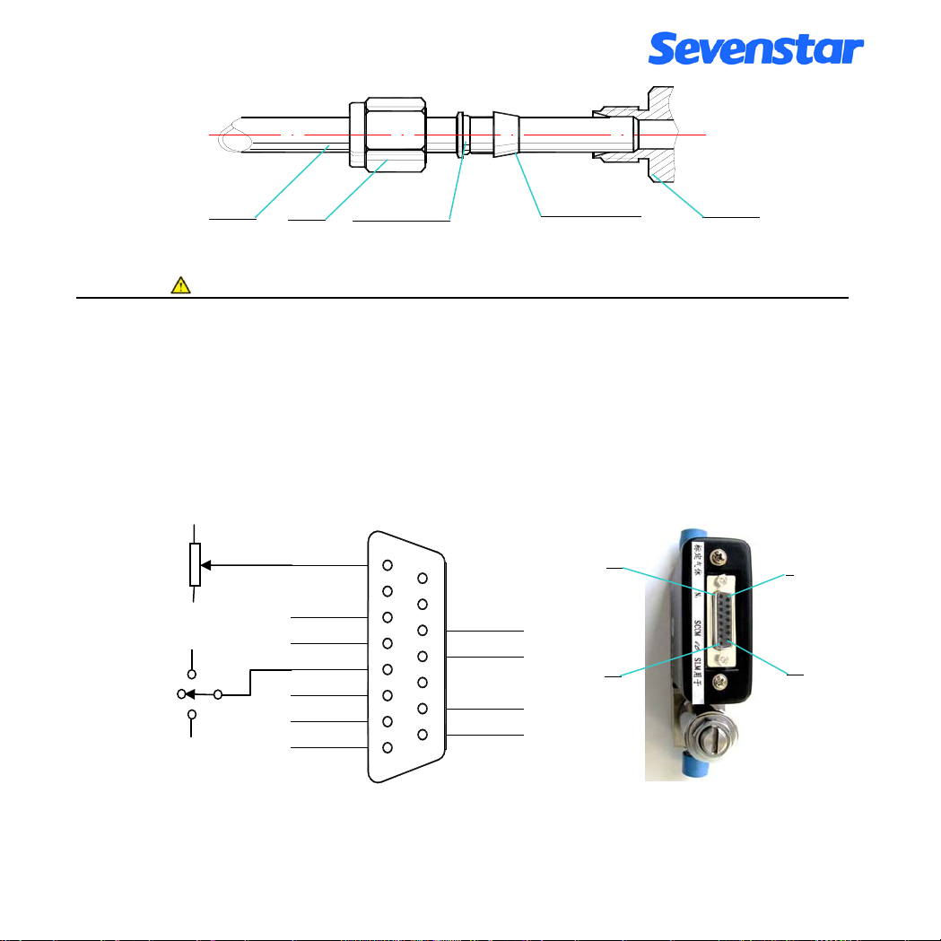
Tube
Nut
Back Ferrule
Front Ferrule
Fittings
Figure 6. Swagelok Connector Installation
Attention :
When installing the fitting, you should manually use spanner to wrench it tighten by 1/2 turn pulling up,
(imported Swagelok should use spanner to be tighten in 1,25 turns) to prove its not blow-by after your
installing the front ferrule ,back ferrule and nut. Please note you should use two spanners to operating,
one spanner for locking the fitting stable and another one for revolving the nut. Especially when yo u
dismantle the tube, you should operate by the two spanners otherwise fitting will become flexible which
will affect its airproof function.
4.4 Electrical Interfacing
Off
Auto
Purge
+15V
-15V
+15V
-15V
Zero adjustment
Power common
Set(0~5VDC)
Valv e d r iv e
Signal common
Output(0~5VDC)
GND
1
2
3
4
5
6
7
8
9
10
11
12
13
14
15
-15V D C
-15V D C
Common
+15VDC
Figure 7. D07-7B Electrical Interfacing
1
8
9
15
Page 9 of 27
Page 42
MFC could begin operating after it was well connected with professional cable and corresponding Flow Readout
Box. 7B-MFC connection is showing in the following figure 7.
Attention :
D07-7B is upgrade of D07-7A; D07-7B applied affixed components and international standard D
connector. Compared with 7A, they have the same position of connector lead but opposition of serial
numbers. 7B could possible substitute for 7A, cables of 7A could directly connect to 7B but only different
of its lock device, normally, it should change its connectors or cables while substitution.
7BM-MFM connector (figure11) is as same as connector of 7B-MFC, only compared with MFC accessories that
lacks of “ Valve drive” and “Set” two wires.
+15V
-15V
Zero adjustment
Power common
Signal common
Output(0~5VDC)
GND
1
2
3
4
5
6
7
8
9
10
11
12
13
14
15
-15VDC
-15VDC
Common
+15VDC
Figure 8. D07-7BM Electrical Connector
Page 10 of 27
Page 43
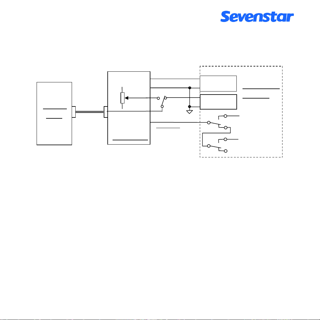
4.5 PC Connections
a. Connection through Flow Readout Box with PC or other external signal. (Figure 9)
MFC or
MFM
Connection
Cable
Flow Signal Output
Signal common
INT
SET
Valve drive
Readout Box
EXT
(ATTENTION:
No “Valve drive” and
“Set” in MFM )
A/D In
Signal common
D/A Out
Signal common
COMPUTER
Or PLC
Off
+15V
Purge
-15V
Auto
Figure9. Connection with PC through Readout Box
When need test the output signal Voltage(0-5VDC), users could connect to the “Flow Signal Output” and the
“Signal common” of external control signal socket of Flow Readout Box, also could directly connect with PC
modulus (A/D) converter, +5.00 V output voltage is corresponding as full scale rating flow rate of MFC. Please
be sure the flow testing output electric current will be no more than 3mA.
When the flow is setting by external signals , it should be turned the switch on “OUT”, meanwhile, it should be
input 0-5.00VDC external voltage from external control socket to the Flow Readout Box. In case of user’s
external potentiometer had settled, it could be used a 3.3K multi-turn potentiometer to connect to the external
control signal socket of “+5.00V” and “signal common”. It also could be directly connecting with modulus (D/A)
converter of PC to achieve auto-control, please be sure the flow setting input resistance should be higher than
100 KΩ.
If PC or PLC need perform the OFF and PURGE function of valve control, it could be accomplished by use two
RELAYS (two sets) transfer contacts. One relay controls OFF and anther one controls PURGE, when these two
relays are not operating then it reaches to auto-control mode. Please be careful, it should be not caused short
circuit by two relays simultaneously operating. Suggested relays connection as method as showing in Figure 11.
Page 11 of 27
Page 44
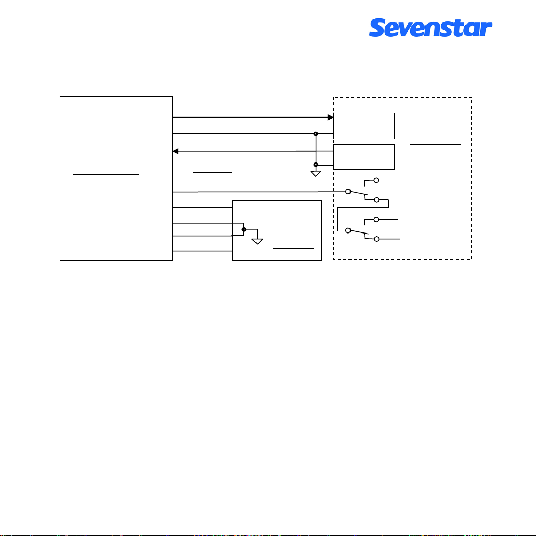
b. PC Directly Connection (Figure 10)
0~+5V
MFC or MFM
Flow Signal Output
Signal common
Set
Valve drive
+15V
common
power common
-15V
0~+5.00
(ATTENTION: No “Valve drive”
and “Set” in MFM )
+15V
COM
-15V
POWER
A/D In
Signal common
D/A Out
Signal common
-15V
+15V
PC or PLC
Auto
Purge
Off
Figure 10. PC Directly Connection
Under the case of MFM/MFC directly connects to PC without Flow Readout Box, ±15V power supply with good
anti-jamming should be provided by user itself; connects SET with PC D/A output; connects “Flow Testing” with
PC A/D input; “Signal common” connects signal reference point; low-current “common” and heavy-current
“power common”-down lead separately, and connects together to the ±15V power supply common port.
If users need PC performs “AUTO”, “OFF” and “PURGE” functions, we suggested connection as showing as in
Figure 13.
4.6 Zero Adjustment
It could be zero adjusted in case of zero excursions while the first time operating or a long period operating.
Users could adjust the Zero potentiometer from side face (showing in figure 15) or adjust it while removed its
overall (showing in figure 16). Please note it should be sure that gas flow tube could not be open while zero
adjustment (or shutoff the valves); it should be warming up not less than 15 minutes, adjustment performs after
its zero moving to the stable stop.
There is another external zero adjustment function, while MFC connected with our new zero adjustment
functional D08 Flow Readout box, it could be achieved by zero potentiometer of display panel. The important is
Page 12 of 27
Page 45
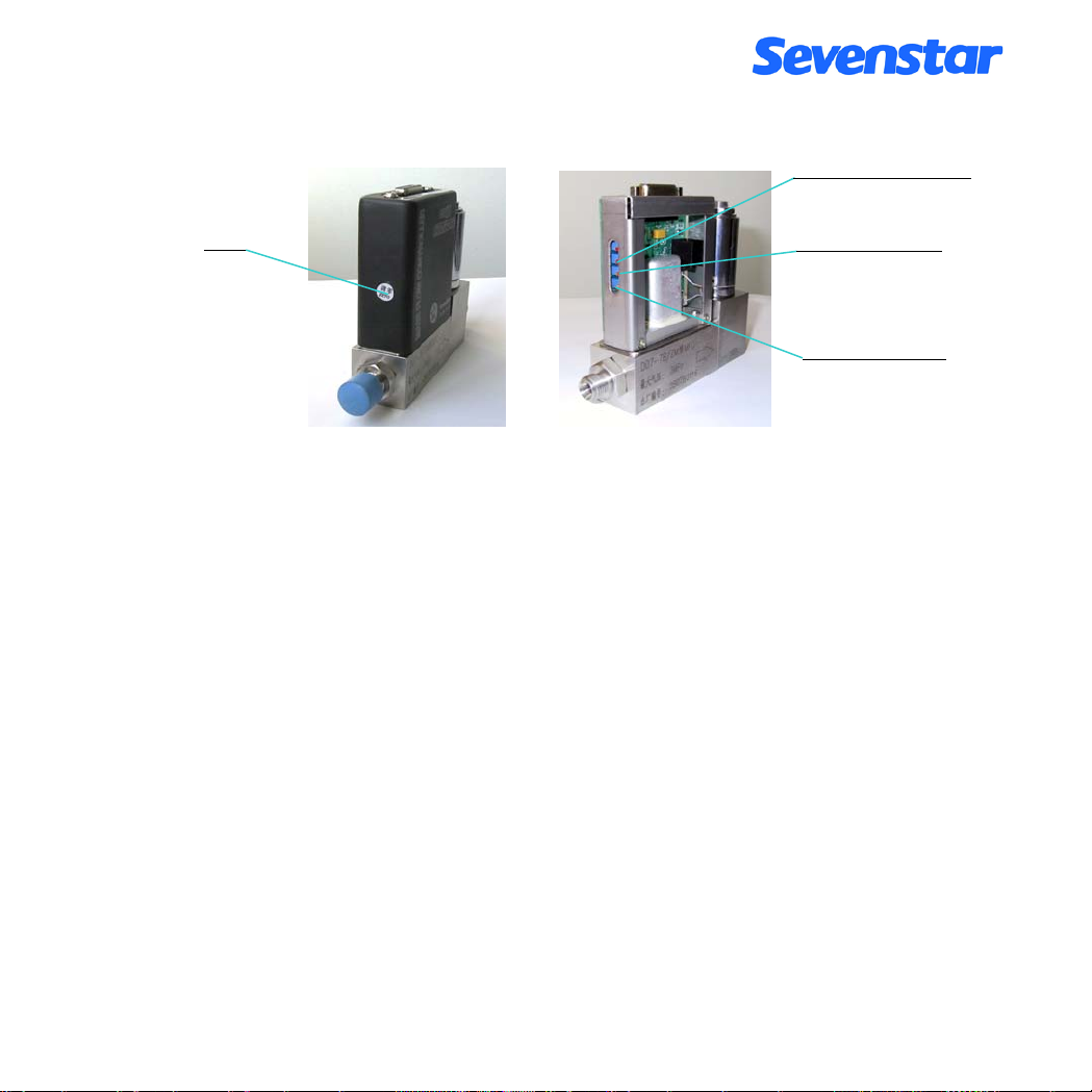
the ranges of external zero adjustment is narrow, when there is big zero excursion happened, it should be better
adjust zero from zero potentiometer of MFC.
Linearity potentiometer
Zero
Span potentiometer
Zero potentiometer
Figure 11. The Position of Potentiometer of 7B & 7BM
Another way to adjust zero is potentiometer adjustment from D08 series Flow Readout box.
Page 13 of 27
Page 46
5. OPERATING INSTRUCTIONS
5.1 MFC Operation
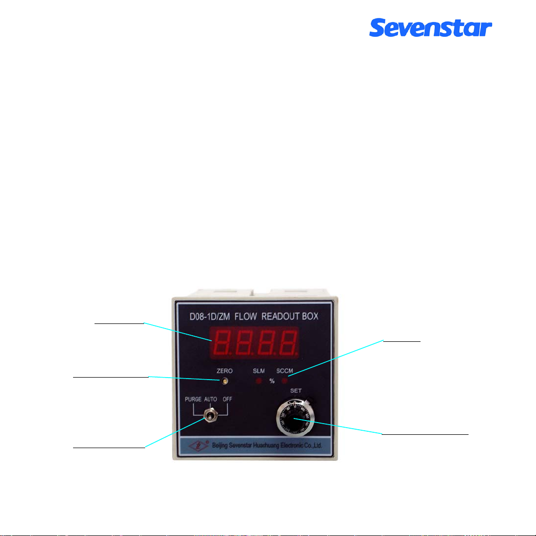
5.1.1 Start Up (Figure 12)
The main operating should perform in the Flow Readout Box. Valve Control Switches and flow setting
potentiometer are in the front of Readout Box panel, the flow setting internal or external signal control switches
are on the back of panel of Readout Box. When the switch is turned on the INT position, the potentiometer will
control flow rate; when the switch is turned on EXT position, the external signal will control flow rate (Please
check out the details in Flow Readout Box Instruction).
a. When valve switch is on the position of AUTO, gas supply should be open first and then turn on the power
supply, the flow rate will not be beyond 5% of presetting after flow soft-start about 20 seconds. General speaking
it should be warming up around 15 minutes in case valves shut off and gas flow cut off, after stable zero
movement, normal operation could begin. If there is big zero excursion, please see the reference 4.5, in the case
of non-gas flow, it’s better adjust zero by zero potentiometer.
b. If Valve switch is on the position of OFF, after power supplying, gas supplying and warming-up, turn switch to
AUTO position, flow rate will reach the presetting 2%(or lower) after a few seconds, which is the suggested
operating method.
Flow Display
Flow Unit
Zero potentiometer
Valve Drive Switch
Flow Set potentiometer
Figure 12. Flow Readout Box Operating Panel
Page 14 of 27
Page 47

c. If Valve switch is on the position of PURGE, the flow rate will reach up to the maximum value after gas and
power supplying, which will have the function of air blasting to the gas circuit.
d. If Valve switch is on the position of AUTO and presetting is not zero, open the gas after power supply, the flow
rate will have a big overshoot and then rapidly reach to the stable presetting value, this kind of operation should
better be avoided.
e. The best operating sequence should be:
1.Open the power supply; 2. Turn the Valve switch on OFF position; 3. Open the gas supply; 4. Warm up for
minutes to have stable zero point movement; 5. Turn the switch on AUTO position; 6. Set flow rate under
request. This is the best way to operate without an overshooting.
5.1.2 PURGE
When need air blasting and cleaning bypass and tube, users could turn the switch on PURGE position, during the
purging, flow rate value should reach up to times or even several decuples of the full scale flow value. If shutoff
gas supplying, it could be vacuum pumping to get rid of MFC internal or upper reaches remained gas matching
request. And then shut off valves, open gas supply again and turn it to AUTO position.
5.1.3 PC Connection By Displayer
Please find the reference in Figure 1 and Figure 9,it should set the switch of displayer to the
EXT and turn switch to the AUTO position, and then startup PC.
5.1.4 Directly PC Connection
Please have the reference in Figure 1 and Figure 10, after MFC warming up, it could have PC startup.
5.1.5 Valves Drive
When the valve switch sets to AUTO position, users could perform valves drive wire of external control signal
socket, please find the reference in Figure 3 and Figure 9. When valve drive wire connects with +15 V, valves
will be shutoff; when valve drive wire connects with –15 V, valves will be turned to the top of maximum to purge
position; when valve drive wire hangs in the air, it’s in the auto-control situation.
5.1.6 Shut Off Operation
After shutoff power supply, flow will be cut off automatically. It should be better shut off gas supply (Turn valve
switch to OFF position and close the cut-off valve of gas circuit) before power supply.
5.2 MFM Operation
5.2.1 Start Up
Please warm up for 15 minutes by power supply before MFM operating.
5.2.2 Testing and Zero Adjustment
Page 15 of 27
Page 48

Please check up zero point of MFM after its warming up (especially for the first time operating), it could have
reference in 4.5, without gas supplying, which could adjust zero by zero potentiometer.
5.2.3 Gas Supply
After zero movement reaches stable, MFM Could have gas supply. Please pay attention to the flow rate, it should
be better operate not beyond full scale range.
5.2.4 Shut Off
Turn off the power supply, which means MFM operating will be terminated, it could not affect the flow rate of
bypass.
Page 16 of 27
Page 49

6. CAUTION
6.1 Medium Forbidden
The gas of using should be purified without dust、liquid and oil stain. When necessary, it should be added filter to
gas circuit to make sure gas purification. If the outlet of MFC connects with liquid sources, which should be
added simple directional valve of MFC outlet to avoid the liquid is refluent to the tube to destroy MFC.
6.2 Corrosive Gas
The materials of bypass are anti-caustic materials like 00Cr17Ni14Mo2(same as 316Lstainless steel), Teflon, and
Viton. When users operate in condition of without vapor, low leakage, regular cleaning and proper operating,
MFC could possible control the normal corrosive gas. Using ammonia, organic solvent gas such as acetone or
other strong caustic gas (like BC13 and BBr3), please informed while your order statements. Valves sealing
materials usually are Viton, for D07-11/11A/12/12A MFC could also used Teflon. While Teflon has been selected,
there maybe leakage happened of valve port, valve sealing leakage rate will lower than 2% of full scale flow rate;
when use the special caustic gas, all sealing materials should be changed relatively.
For the cases that the MFC/MFM used with toxic, pyrophoric, flammable or corrosive gas, you should
ensure that the fixing and fitting are airtight. It becomes necessary to remove the controller from the
system, purge the controller thoroughly with a dry inert gas such as nitrogen, before disconnecting the gas
connections. Failure to purge the controller could cause a fire or explosion resulting in death.
6.3 Seal of Valves
The Valve of MFC is an electric-magnetic valve for adjustment, which is not a solenoid plug valve so that could
not perform that kind of function. Users should better have that plug valve by themselves. Especially when users
operate with caustic gas, general speaking, it should separately add one cut-off valve of MFC inlet and outlet to
protect operating security. After a long period operating, if the leakage rate of MFC valve outlet is not beyond 2%
F.S, which is the standard situation. Otherwise, it should be under maintaining.
6.4 Valves Operating
When valve is operating PURGE, which should not be directly turned to AUTO, operation should be turned the
switch to OFF position and then turn it into AUTO to operating.
6.5 Installation Position
Keeping installation surface horizontal while installation. Please provide the installation position when ordering
the MFC. We will calibrate products according to the requirement of customers. The MFC might show the zero
drift if it is not installed as the same position of calibration. Customer can adjust zero to fix it.
Page 17 of 27
Page 50

6.6 Pressure Resistance
Please be caution for the medium operating pressure of MFC, it should not be beyond the rage of specification of
inlet and outlet. Especially while operating under the high-pressure situation, the big differential pressure will
affect flow fail to shut off or lower adjustment. In case of using heavy flow rate of MFC, please be sure
appropriately widen tube and reduce gas internal resistance, if operating differential pressure is lower than the
value of request, it might could not be reach to the full scale flow rate value.
6.7 Calibration and Conversion
D07 series is calibrated by nitrogen. Other gas calibrations please inform while your order statements. When the
nitrogen calibration users use other gas operating, it could convert and calculate used gas flow rate by conversion
coefficient of appendix 9.1. Which means users could multiply the readout flow rate from MFC Flow Readout
box with the used gas corresponding conversion coefficient, the result will be the used gas corresponding mass
flow rate of standard situation.
For example, there is 100 SCCM (N2) calibrated MFC, the flow rate is displayed 86 SCCM while firedamp
flowing, the conversion coefficient of firedamp is 0.719 from reference of appendix 9.2, the real firedamp flow
rate is 86 × 0.719 which is 61.8 SCCM.
If users use the mixture gas, it could be calculated the conversion coefficient by the method which introducing in
appendix 9.2.
Page 18 of 27
Page 51

6.8 D07-7B, 7BM Ordering Code
D07-[t] [g,g,g] [r,r,r,r] [f,f] [s] [m] [d]
[t] –Type Number
- [7B ] MFC
- [7BM] MFM
[g,g,g] –Gas
Please consult SEMI52-0302
For Example:
-[ 013 ] N
-[ 007 ] H
2
2
-[ 000 ] Mixture gases (please consult [d] for detail)
[r,r,r,r] –Flow Range Full Scale
- [ 005C] 5SCCM
- [ 010C] 10SCCM
- [ 020C] 20SCCM
- [ 030C] 30SCCM
- [ 050C] 50SCCM
- [ 100C] 100SCCM
- [ 200C] 200SCCM
- [ 300C] 300SCCM
- [ 500C] 500SCCM
- [ 001L] 1SLM
- [ 002L] 2SLM
- [ 003L] 3SLM
- [ 005L] 5SLM
- [ 010L] 10SLM
- [ 000C] Customer Special Request (please consult [d] for detail)
Page 19 of 27
Page 52

D07-[t] [g,g,g] [r,r,r,r] [f,f] [s] [m] [d]
[f,f] –Inlet and Outlet Fittings
-[AA ] Swagelokφ3mm
-[GG] Swagelokφ6mm
-[BB ]
Swagelok 1/8"
-[CC ]
Swagelok 1/4"
-[MM] VCR 1/4"
-[XX ]
Customer Special fittings (please consult [d] for detail)
[s] –Seal Materials
-[ V ] Viton
-[ N ] Neoprene
[m] –Mounting Position
-[ H ] Horizontal
-[ E ] HESD(Horizontal Edge Side Down)
-[ U ] Vertical Inlet Up
-[ D ] Vertical Inlet Down
[d] –Description
-[ ] Default Value:
The letters on cover and tag:in Chinese
Differential Pressure:D07-7B: (0.1 ~ 0.5) MPa (14.5~72.5 psid)
D07-7BM:< 0.01MPa (1.5psid)
Max Operating Pressure: 3 MPa (435.1 psig)
Calibration Temperature:(22±2)℃
-[ S ] Customer Special Requirements:
For Example:The letters on cover and tag:in English;Customer Special Full Scale:9SLM;The proportion
of Mixture gases should be indicated:N
Pressure:(0.05 ~ 0.3) MPa;Customer Calibration Temperature:40℃ and other customer
special requirements.
For Example: D07-7B007001LCCNUS
D07-7B 007 001L CC N U S
2 (60%) + CO2(40%);Customer Differential
Page 20 of 27
Page 53

Type Number:D07-7B MFC
Gas:H2
Flow Range Full Scale:1SLM
Inlet and Outlet Fittings:Swagelok 1/4"
Seal Materials: NEOPRENE
Mounting Position:Vertical inlet up
Customer Special Requirements:For Example:The letters on cover and
tag:in English;Differential Pressure:(0.05~0.3) MPa;
Customer Special fittings(According to drawing) ;Customer
Special Calibration Temperature:40℃.
Page 21 of 27
Page 54

7. TROUBLESHOOTING
Table 3. Failure Handling
NO. FAILURE CAUSE TREATMENT
1 There is no gas flow
after turn on.
2 In case of turning on
but without gas flow,
the flow rate testing is
error.
3 In case of valve
shutting off, there is
still heavy flow rate
passing.
4 The flow rate display
could not reach to full
scale flow rate value.
1.1 Gas flow is shutting off, no gas
inputting
1.2 Valve control switch is shutoff Turn the switch to CONTROL or
1.3 No setting signal Check potentiometer or “In/Out” switch
1.4 Filter is blocked * Change a new filter
1.5 Valve failure Test or *clean valve
1.6 Circuit failure *Repair the electric circuit
2.1 Zero excursion Adjust the zeroing potentiometer
2.2 Power supply failure *Check input/output voltages( ±
2.3 Sensor failure *Replace the new sensor
2.4 Amplifier or other circuits failure *Replace amplifier or repair circuit
3.1 Over- load pressure of input
outlet, the differential pressure between
inlet and outlet is beyond rating.
3.2 Pollution of valve *Clean valve and replace seal ring
3.3 Valve failure *Re-adjust solenoid control valve
4.1 Pressure is lower than the rating Heighten the inlet pressure
4.2 Block of bypass *Clean bypass
4.3 Setting voltage is less than5.00V *Check the setting Voltage
Check the gas sourcing and make it
open
PURGE
setting position
15VDC, +5.00VDC)
Reduce the inlet operating pressure to
decrease differential pressure.
4.4 Others trouble *Repair circuit etc.
Page 22 of 27
Page 55

NO. FAILURE CAUSE TREATMENT
5 Fluctuant flow rate
6 Disturbed by high
frequency power
sourcing
7 Flow display is in-
accurate
passing while zero
setting.
9 The heavy flow is
passing but no
outputting display
10 Without gas flow, Zero
is fluctuate or
excursion happened.
5.1 Inlet pressure is too low or
instable
5.2. High internal gas resistance Lessen internal resistance (The heavy
5.3 Circuit or valve failure *Repair and adjust
6.1 Earth wire and zero wire
connecting of power supply is error
6.2 Signal reference port connecting
problem
6.3 Inter space disturbing
7.1 The range or unit of Display is not
matching to controller.
7.2 Bypass is polluted to cause the
flow rate excursion.
7.3 Zero excursion happened to be
instable.
8.1 Valves leakage *Repair solenoid control valve 8 There is still flow
8.2 Zero point is moving less than 0 Adjust zero
9.1 Block of sensor *Repair and replace the new sensor
9.2 Circuit failure *Repair circuit
10.1 Sensor failure *Replace a new sensor
Heighten inlet pressure
gas flow should have big valve open,
widen tube to parallel connecting gas
bottles to improve gas supply capacity.)
Check the earth wire connection, should
be one port connection.
Check signal connecting wire.
*Re-adjust Display
*Clean MFC and re-calibrate it
* Change sensor and repair circuit
Should add filter to block gas dust.
Using special gas should be sure of
good tube sealing and gas dryness.
Attention
:
* Mark indicates that reparation and adjustment must be dealt under specialist advices。
Page 23 of 27
Page 56

8. WARRANTY & SERVICE
8.1 Product Warranty
a. Our products are guaranteed within 2 years warranty against defects in materials and workmanship if used
in accordance with specifications and not subject to physical damage, contamination, alteration or retrofit.
b. Buyers undertake to check and inspect the goods and to notify SevenStar of shipment incidents by fax,
phone or e-mail as soon as possible after receipting the goods.
c. During the warranty period, products must only be repaired by Sevenstar or authorized SevenStar service
centers; otherwise, the SevenStar product warranty will be invalidated.
d. Repairs will be performed free of charge during the two-year warranty period. If MFCs/MFMs are out of
warranty, SevenStar will notify the owner of replacement or repair costs before proceeding. Factory service
and repairs are guaranteed 90 days. The warranty excludes consumable materials and wear parts (in teflon,
viton, etc.).
e. No MFC/MFM used with dangerous gas will be accepted for repair or warranty without a decontamination
and purge certificate.
8.2 Specific warranty requirements are as follows :
a. Gas must be clean and particle-free, which means a filter( <30μ) must be fitted in the gas line upstream of
the MFC/MFM.
b. Gas must comply with the pressure specifications, and never exceed the rated value.
c. Process gas should be in line with the seal materials chosen in the order, especially in case of corrosive gas.
We shall not be responsible for any damage caused by changing process gas or choosing the wrong seal
materials in order.
d. Electrical connection requirements are as follows: The system must be wired carefully: non-observance of
the pin out may irreversibly damage the electronic board inside the products. If user self scheme power
supply of MFCs, a stable and anti-jamming power supply is required, with ripple below 5mV.
e. Gas connections: the fittings must be handled carefully. We guarantee that all fittings have been individually
inspected and are scratch-free.
f. The MFC/MFM must not be dismounted: the MFC/MFM warranty will be invalidated if the seal between
the MFC/MFM block and cover is torn.
8.3 Service
Our product engineer will help you with issues related to operation, calibration, installation, process specification,
gas convention, etc. And we also provide you with technology support& maintenances, and products operation
training.
Please visit mfc.sevenstar.com.cn
for relevant information and the locations of our service centers.
Page 24 of 27
Page 57

9. APPENDIX
9.1 Mass Flow Conversion Factors
Table 4. Conversion Factors
GAS
Air 008 0.2400 1.2930 1.006
Ar 004 0.1250 1.7837 1.415
AsH3 035 0.1168 3.4780 0.673
BBr3 079 0.0647 11.1800 0.378
BCl3 070 0.1217 5.2270 0.430
BF3 048 0.1779 3.0250 0.508
B2H6 058 0.5020 1.2350 0.441
CCl4 101 0.1297 6.8600 0.307
CF4 063 0.1659 3.9636 0.420
CH4 028 0.5318 0.7150 0.719
C2H2 042 0.4049 1.1620 0.581
C2H4 038 0.3658 1.2510 0.598
C2H6 054 0.4241 1.3420 0.481
C3H4 068 0.3633 1.7870 0.421
C3H6 069 0.3659 1.8770 0.398
C3H8 089 0.3990 1.9670 0.348
C4H6 093 0.3515 2.4130 0.322
C4H8 104 0.3723 2.5030 0.294
C4H10 111 0.4130 2.5930 0.255
C5H12 240 0.3916 3.2190 0.217
CH3OH 176 0.3277 1.4300 0.584
C2H6O 136 0.3398 2.0550 0.392
C2H3Cl3 112 0.1654 5.9500 0.278
CO 009 0.2488 1.2500 1.000
CO2 025 0.2017 1.9640 0.737
C2N2 059 0.2608 2.3220 0.452
Cl2 019 0.1145 3.1630 0.858
D2 014 1.7325 0.1798 0.998
F2 018 0.1970 1.6950 0.931
GeCl4 113 0.1072 9.5650 0.267
GAS CODE
(SEMIE52-0302)
HEAT
( Cal/g )℃
ρ
(g/l 0 )℃
Factors
Page 25 of 27
Page 58

Continue To Table 4. Conversion Factors
GAS
GeH4 043 0.1405 3.4180 0.569
H2 007 3.4224 0.0899 1.010
HBr 010 0.0861 3.6100 1.000
HCl 011 0.1911 1.6270 1.000
HF 012 0.3482 0.8930 1.000
HI 017 0.0545 5.707 0.999
H2S 022 0.2278 1.5200 0.844
He 001 1.2418 0.1786 1.415
Kr 005 0.0593 3.7390 1.415
N2 013 0.2486 1.2500 1.000
Ne 002 0.2464 0.9000 1.415
NH3 029 0.5005 0.7600 0.719
NO 016 0.2378 1.3390 0.976
NO2 026 0.1923 2.0520 0.741
N2O 027 0.2098 1.9640 0.709
O2 015 0.2196 1.4270 0.992
PCl3 193 0.1247 6.1270 0.358
PH3 031 0.2610 1.5170 0.691
PF5 143 0.1611 5.6200 0.302
POCl3 102 0.1324 6.8450 0.302
SiCl4 108 0.1270 7.5847 0.284
SiF4 088 0.1692 4.6430 0.348
SiH4 039 0.3189 1.4330 0.599
SiH2Cl2 067 0.1472 4.5060 0.412
SiHCl3 147 0.1332 6.0430 0.340
SF6 110 0.1588 6.5160 0.264
SO2 032 0.14890 2.8580 0.687
TiCl4 114 0.1572 8.4650 0.206
WF6 121 0.0956 13.2900 0.215
Xe 006 0.0379 5.8580 1.415
GAS CODE
(SEMIE52-0302)
HEAT
( Cal/g )℃
ρ
(g/l 0 )℃
Factors
Page 26 of 27
Page 59

9.2 Conversion Factors Instruction
MFC and MFM are standard calibrated by N2 while it’s out of factory. Other gas calibrations can be
approximated by converting of conversion factors of our instruction. While using other gas operating:
One single gas: The conversion factors could find out in the users specification instruction.
A mixture of two or more gases: Assume there is “n” sorts of gases, could calculate the conversion factors C by
the following formula:
Basic Formula: C=0.3106 N /ρ(Cp)
ρ — Density of the gas
Cp — Specific heat of the gas
N — Structure factors of gas-molecule (See Table 5.)
Table 5. Gas-Molecule Composing factors
COMPOSITION EXAMPLE N VALUE
Single atom numerator Ar He 1.01
Double atom numerator CO N
2
Tree atom numerator CO2 NO
Multi-atom numerator NH3 C4H
2
8
1.00
0.94
0.88
For mixture gases: N =N1 (ω1/ωT )+N2 (ω2/ωT ) + ··· + Nn (ωn/ωT )
Then:
0.3106 [N1 (ω1/ωT) + N2 (ω2/ωT) + ··· + Nn (ωn/ωT)]
C = ————————————————————————
ρ1Cp1 (ω1/ωT )+ ρ2Cp2 (ω2/ωT )+ ··· + ρnCpn (ωn/ωT)
ω
…ωn — The flow of single gas
1
ω
— The flow of mixture gas
T
ρ
— The density of single gas
1…ρn
CP
…CPn —Specific heat of the single gas
1
N
—Structure factors of gas-molecule (See Table 5.)
1…Nn
Attention :
1) Standard:Temperature 273.15K (0 ºC ); Air Pressure— 101325 Pa (760mm Hg)
2) Please feel free to contact us if the request gas conversion factors could not be found in our
appendix.
Page 27 of 27
Page 60

*Description may be changed following improvements to product. The information
contained in this document is subject to change without notice
*If there is any mistake in this uses manual, please feel free to contact us.
*©2010 Beijing Sevenstar Electronics Co.,Ltd
Beijing Sevenstar Qualiflow Electronic Equipment Manufacturing Co.,Ltd.
D07 Series
Mass Flow Controller
Beijing Sevenstar Electronics Co., Ltd
Mass Flow Meter Subsidiary Co., Ltd
Address: No.1 Jiu x ianqiao East Rd., Chaoyang District, Beijing, China
P.O.BOX 3#741, Beijing, China
Post code: 100015
Tel: (+86)-10-64362939
(+86)-10-64361831 ext. 8491 or 8315
Fax: (+86)-10-64362923 or 64362939
Homepage: http://mfc.sevenstar.com.cn
E-Mail: [email protected]
Shanghai Office: Room 1916, Unicom International Tower, NO.547 Tianm u West
Road, Zhabei District, Shanghai, 200070, China
Tel: (+86)-21-33030324
Fax: (+86)-21-63533265
Shenzhen Office: Room 712, Section B, Qiche Tower, No.45 Zhenhua Road,
Futian District, Shenzhen, China
Zip code: 518031
Tel: (+86)-755-88290258
Fax: (+86)-755-88294770
All rights reserved.
 Loading...