

Page 1
Setra Velocity Monitor
SRIMV
Installation and Operation Manual
1
Page 2

2
Page 3

Table of Contents
1.0 Features and Intended Use
2.0 SRIMV Included parts
3.0 Installation
4.0 Menu Navigation and Configuration
5.0 Setting up the SRIMV menu
3
Page 4

1.0 FEATURES
The SRIMV is a multi-mode (air velocity, flow, pressure, temperature and humidity) monitor. It has a 3
color ba cklight display, a digital input for a door switch, 2 analog inputs for temperature and humidity,
1 relay output for remote alarm indication and an internal p ressure sensor. It can display and alarm on
Velocity, Flow, Pressure, Temperature and Humidity parameters.
User Interface
• Large LCD 2 line display shows values of the monitored parameters
• Green (Normal), Yellow (Warning), Red (Alarm) Backlit display for indicatin g the status
• Membrane keypad for ease of configuration and men u navigation
• Password Protection for security
Audible Visual and Remote Alarms
• Color Backlight LEDs
• Alarm on Pressure, Velocity, Flow, Temperature and Humidity
• Audible Buzzer
• Alarm delay, mute timeout, alarm enable/disable, buzzer enable/disable
• SPDT Relay for remote alarms, including Setra Remote Annunciator (SRAN)
Ease of Installation and Calibr a tion
• Flush mount (mounts flush to wall surface) and duct mount (surface mount) versions; both are
wipe-down compatible for decontamination
• Rotate-able pressure fittings to eliminate crimping of pressures hoses, allows installation
flexibility
• Snap on cover, no visible fasteners
• Modular plug-in design using sub-base. Simultaneous electrical and plumbing connections
reduce initial installation and c a libration costs. Unit can be calibrated in house or sent for
calibration service without removing the wiring or plumbing
• Push button zero and span calibration, no potentiometer adjustments
• PG9 and Conduit fitting in same unit, field sele c ta ble
Versatile
• Field selectable outputs, 4-20 mA, 0-5 VDC or 0-10 VDC
• One unit that can be field configurable for almost all duct and room measurement applications
4
Page 5
2.0 SRIMV Included Parts
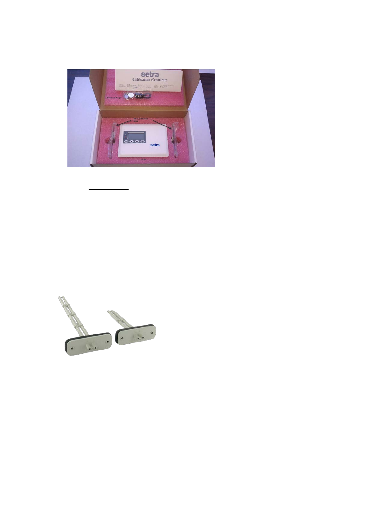
Fig. 2-1 Parts Provided
The SRIMV parts list includ e s:
• SRIMV Velocity Monitor
• Accessories: ordered separately
For Velocity and Flow measurement a Pitot tube, averaging probe or flow station is required as an input
to the pressure ports on the SRIMV. Setra offers the following averaging probe.
Averaging Flow sensor: Part # 242915-xx
The SRIMV can be used with any manufacturer’s probe. The “k” factor flow coefficient must be
entered into the SRIMV at commissioning. T he d e fault setti ng as shipped is K=1. K factor changes
based on probe length.
Installation
The 242915-xx units utilizes 1/4 ID, 3/8 OD tubing. First check that there are
no sharp bends in the tubing at any connection. Connect the “H” Po rt to the high input on the SRIMV
units. Conne ct the “L” Port to the low input on unit.
5
Page 6

Approximate K factors for models:
242915-01: 1.32
242915-02: 1.39
242915-03: 1.46
242915-04: 1.46
242915-05: 1.58
242915-06: 1.67
Mounting
1. Install the unit horizontally to ensure accurate readings fo r units ranging
from 3-5/32 to 9-29/32 . If using a unit longer than the 242915-05, which is 9-
29/32 , vertical mounting is recommended.
2. Determine the duct’s flow direction and install the model 2429150-xx based on
the unit’s flow arrow imprint.
3. Cut a 7/8 hole in the ducting to accept the unit; tip should be at least to the center of duct.
4. Attach using two self-tapping screws inserted in the 3/16 mounting hoes.
3.0 Installation
The SRIMV is available i n two models suitable for wall (flush mount) and surface
mounting (panel mounting). The front panel of the product and the rear housing are snapped
together. The two snaps are located on the left and right sides of the front p a nel. A 1.5mm(1/16
inch)Allen wrench or paper clip can be used to open the concealed snap fastening system.
The rear housing can be used to mount to a wall or into a 3 gang “off the shelf” electrical box.
Conduit (1/2”) or a PG9 cable connection are available for wiring to the terminals at the rear of the
unit. The rear housing acts much li ke a thermostat sub-base that does not have to be removed once
installed.
The front bezel contains the pressure sensor, PCBA and display. It is a complete module that can
be calibrated. The pressure and electrical connectors are disconnected simultaneously when the
front bezel is removed.
Before installing, determine a good installation location. For flush mount applications, the corridor
outside the room i s preferred. For surface mount applications the unit may be mounted on the duct
work (avoid high vibration), a stable surface near the ductwork or inside a panel.
6
Page 7
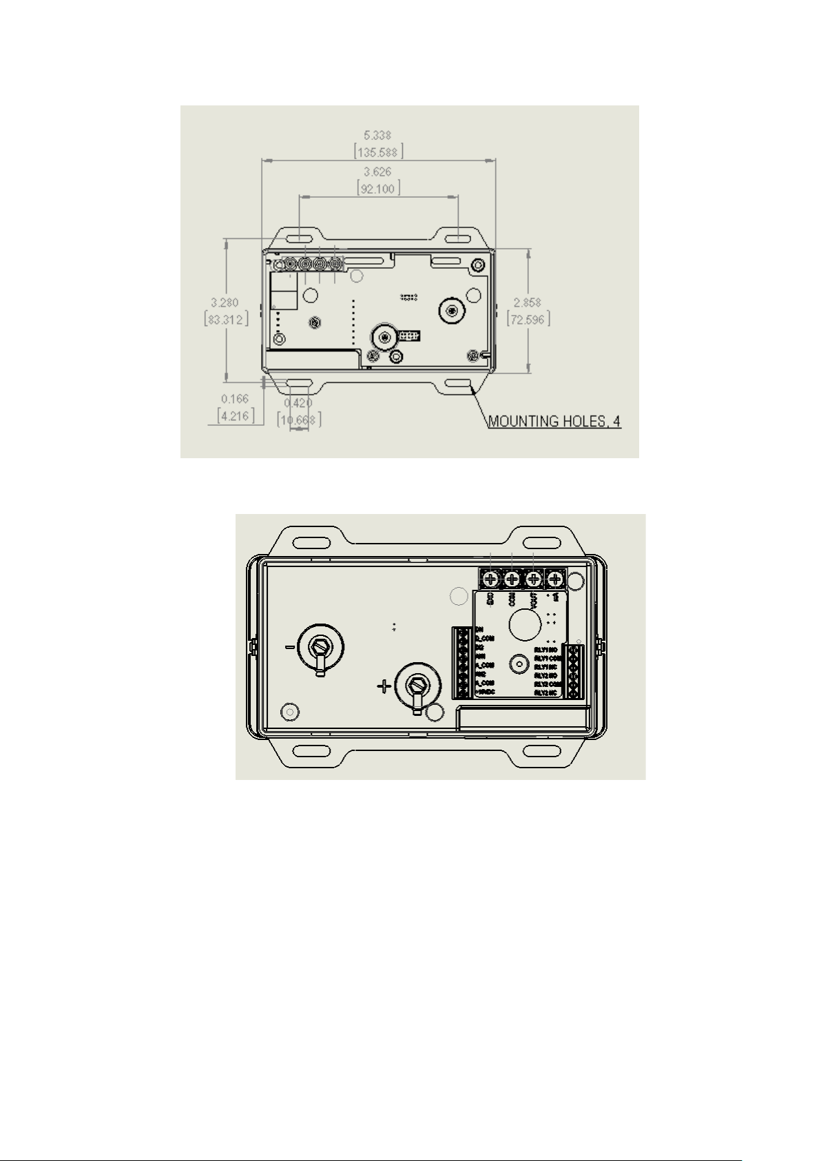
Fig 3-1 Wall (Flush) mount housing dimensions, front view
Fig 3-2 SRIMV Wall (Flush) mount ho us ing rear
view of pressure fittings and elec trical terminations
Unpack the product box. Do not remove the protective film on the fro nt d isplay screen until after
installation to prevent scratching of the display during the installation process. Remove parts and place
them on flat surface. Apply pr essure on the side of the box to open the snap fit or use an Allen wrench
or paper clip as shown See Figure 1-2. First one side then the other, then pull the bezel forward to
remove it fr om the housing.
7
Page 8
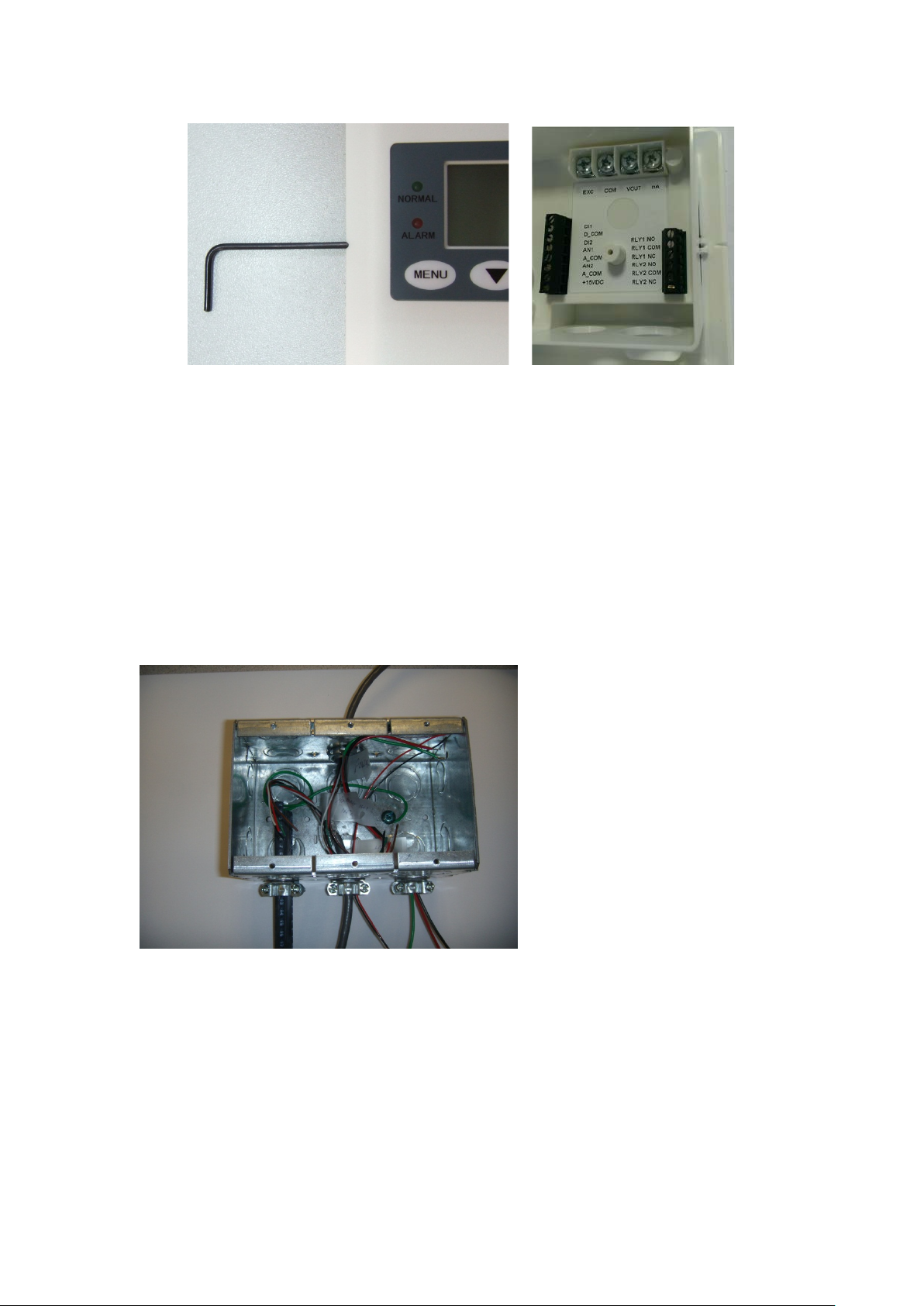
Fig. 3-4 Removing bezel from the base
Plumbing and Wiring to the Electrical Box (Rough in)
Flush mounting:
Use a 3 gang electrical box RACO 697 or equivalent or mount directly into the wall. If mounting directly
into the wall create an opening approximately 2.8” (71 mm) by 5.4” (134 mm). If using the 3 gang bo x
use #6 machine screws to mount the ears o f the SRIM rear housing to the electrical box. If mounting
directly into the wall without an electrical box, use drywall screws to mount the 4 ears of the SRIMV
box to the wall.
Fig. 3-5 Rough Plumbing and Wiring to Rough-in box, Flush Mount Uni t
8
Page 9

Fig. 3-6 Wiring Diagram SRIMV
9
Page 10

Fig 3-7 Pressure ports and electrical terminals, SRIMV
Rotating pressure Fittings, ca n point
up or down, SRIMV only
- Pressure
Terminal Function
EXC 18-30 VDC, 24 +/- 20% VAC
COM Power Supp ly COM and Analog Out COM
VOUT Analog Output + (VDC mode) 0-5 VDC, 0-10 VDC
mA Analog Output (mA output mode) 4-20mA
D1 Door status, wire to one side of NO contact
D_COM Door status, wire to other side of NO contact
DI2 Not used
AN1 + output of temperature sensor (if used) 0-5, 1-5, 0-10 VDC
A_COM
Common output of temperature and humidity sensors (if
used)
AN2 + output of humidity sensor (if used) 0-5, 1-5, 0-10 VDC
COM 15V Power Common (return)
+15VDC Power for remote annunciator (if used) 15 VDC, 50mA
RLY1 NO
RLY1
COM
Relay 1 Normally open contact, 3A 120 VAC, 28 VAC,
resistive load
Relay 1 Common contact
RLY1 NC Relay 1 Normally closed contact
RLY2 NO Not used
RLY2
COM
Not used
RLY2 NC Not used
Table 1 Wiring SRIMV
10
+(High)
Pressure
Pull wires through the openings in the
bottom of the base. ½” Conduit or
PG9 fitting openings are provided.
Page 11

Figure 3-8 Wiring, SRIMV
Notes:
Relay 1 (RLY1) is a SPDT relay that can be used to signal a remote unit of an al arm condition. The
relay contacts are rated for 3 A, 120 VAC, 3A, 28VDC
11
Page 12

Fig. 3-9 Installed plugs on unused openings in the base.
Connect the pressure tubes to the high and low pressu re ports. W ire to t he electrical term inals on the back
of the housing. If desired, place electrical plugs on the unused holes in the base.
Complete the installation by installing the bezel onto the base by aligning the two and pushing the
bezel into the base until the bezel snaps to the base on the 2 sides. Be sure to carefully align the 2 parts
and push straight in. There are alignment features on the front bezel and rear housing.
4. 0 Menu Navigation and Configuration
The LCD displa y is s tandard o n the SRIMV and the display provides valuable feedback during
configuration and for user feedback in the normal and alarm modes.
Apply 24 VDC or 24 VAC power.
Menu Flow Chart. The SRIMV flow chart is available on the setra.com web site to help with set up and
configuration. Use the QR code to get to setra.com.
12
Page 13

Display Parameters
Unit in the normal state, line 1 indicates differential pressure, veloc ity or flow and the corresponding
engineering units. Line 2 indicates the temperature and humidity reading, if enabled. The green
backlight indicates that the velocity (or pressure or f low), the temperature and humidity is within the
allowable alarm limits. Note that the alarm will occur if any of the 3 monitored parameters are outside
of their respective limits.
Unit shown in alarm state. There will be a red backlight with an arrow indicating which parameter is in
alarm and if it is above or below alarm limits. The audible buzzer will also be active if it has been
enabled.
13
Page 14

Menu Operation
Menu key – Provides access to the menu structure
Down arrow key – Allows selection of numerical parameters. Pushing the down arrow causes the digits
to move upwards in a 1 digit count and will wrap around. The cursor be low the indicated item in the
current menu item indicates that this is the digit that is being changed. If you don’t need to make a
change to that position press the enter key to move to the next position to the right.
Enter key – Use this key to move left to right in a curr ent menu screen. It is also used to save the
current menu items selected settings, or to confirm the current menu operation. Press the Enter key to
save the current settings; the display will show the current setting value and flas h twice, and prompt the
user that the value currentl y se t has been saved. There is no “back” button, so if the user proceeds past
the desire parameter they must go back to the start of that menu screen.
Return/Silence button – This button provides a quick way to return to the home screen from anywhere
within the menu structure. It has the secondar y purpose of temporarily silencing the audible alarm. If
the mute timeout setting is reached the aud ible alarm will again sound.
Menu Screens
1. Common Configuration
Menu Setup
Engineering Units
Output Mode
Runs through the setup screens to set all
parameters to desired set points. Below are all of
the parameters that must be selected.
User selectable for either English or Metric
units. Choose “enter” to activate the engineering
units menu. The engineering units will flash and
then press the “down arrow” to select desired
units. Press “enter” to select.
User selectable output mode: 0-5V, 0-10V or 420mA. Choose “enter” to activate the o utput
mode menu. The output mode will flash and t hen
press the “down arrow” to select desired mode.
Press “enter” to select.
14
Page 15

Velocity, Flow, Pressure, ACH Selection
Alarm Delay
Mute Timeout
Buzzer Enable
Door Switch
User Selectable for Velocity, Flow, Pressure or
Air Changes per Hour. Whichever option is
chosen in thi s menu will be shown as the default
in the secondar y men u und er the
V/Flow/Pressure section. Choose “enter” to
activate the V/Flow/Press menu. The menu will
flash and then press the “down arrow” to select
desired mode. Press “enter” to select.
Set the desired time for Alarm Delay. Choose
“enter” to activate the Alarm Delay menu. The
menu will flash, then press the “down arrow” to
select correct digit: “enter” moves to next digit.
Sets the desired amount of time to engage Mute
Timeout. Choose “enter” to activate the Mute
timeout menu. The menu will flash, then press
the “down arrow” to select correct digit: “enter
moves to next digit.
Enables or disables the audible buzzer alarm.
Choose “enter” to activate the Buzzer Enable
menu. The menu will fla sh, then press t he “down
arrow” to select enable or disable. Press “enter”
to select.
Door switch enable/disable. Enable if used with
a door switch to detect if door is open.
15
Page 16

Password Enab l e
Filter Setting
2. V/Flow/Pressure/ACH
If Velocity is chosen:
K Factor
Enables or disables the 4 digit numeric
password.
(0-99) is the filter setting. This is the number of
samples used to take an average; it is a weighted
rolling average, so the higher the number the
more filteri ng is done to smooth out the output
and display readings. Thus, for turbulent flows it
is recommended to use a higher filter number. For
faster response you would use smaller setting.
After choosing to display and monitor Velocity
from the Common Configure section, set the
parameters for that output.
The K factor is provided by the manufacturer of
the static pressure probe or Pitot tube
Barometric Pressure
16
Set current barometric pressure conditions. This
can either be entered manually or it will be set to
the standard default of 29.92 in Hg. Barometric
Pressure effects the flow rate due to changes in
air density. Choose “enter” to activate the
Barometric Pressure menu. The menu will flash,
then press the “down arrow” to select desired
digit. Press “enter” to sele ct and move to next
digit.
Page 17

Temperature Source
Enter T emperature
Zero Calibration
Choose between an analog sensor input (from
external sensor) or “set-up”. The sensor input
comes from the external sensor, whereas the
“set-up” option is added manually if there is no
temperature sensor used. Temp is used to
calculate air density; Default is 70 degrees
Fahrenheit or 21.1 degrees Celsius. Choose
“enter” to activate the Temp Source menu. The
menu will flash, then press the “down arrow” to
select desired temp source. Press “enter” to
select.
If Temp Source “set up” is chosen, manually
enter the temperature. Choose “enter” to activate
the Enter Temp menu. The menu will flash, then
press the “down arrow” to select desired d igit.
Press “enter” to select and move to nex t digit.
“Tares” out any Zero pressure error. This must
be done with Zero pressure applied to the unit.
V elocity Alarm High Limit
17
Sets the alarm for the high side velocity limit.
Choose “enter” to activate the V Alarm H Limit
menu. The menu will fla sh, then press t he “down
arrow” to select desired digit. Press “enter” to
select and move to next digit.
Page 18

V elocity Alarm Low Limit
V elocity Alarm Enable
Velocity Range
If Flow is cho sen:
K Factor
Sets the alarm for the low side velocity limit.
Choose “enter” to activate the V Alarm L Limit
menu. The menu will fla sh, then press t he “down
arrow” to select desired digit. Press “enter” to
select and move to next digit.
Enables or disables the velocity Alarm. Choose
“enter” to activate the V Alarm menu. The menu
will flash, then press t he “down arrow” to select
desired mode. Press “enter” to select.
Sets velocity range in either ft/min or m/s.
Choose “enter” to activate the Velocity Range
menu. The menu will flash, then p ress the “down
arrow” to select desired units. Press “enter” to
select.
After choosing to display and monitor flow from
the Common Configure section, set the
parameters for that output.
The K factor is provided by the manufacturer of
the static pressure probe or Pitot tube and varies
by probe length.
18
Page 19

Barometric Pressure
Temperature Source
Set current barometric pressure conditions. This
can either be entered manually or it will be set to
the standard default of 29.92 in Hg. Barometric
Pressure effects the flow rate due to changes in
air density. Choose “enter” to activate the
Barometric Pressure menu. The menu will flash,
then press the “down arrow” to select desired
digit. Press “enter” to sele ct and move to next
digit.
Choose between an analog se nsor input (from
external sensor) or “set-up”. The sensor input
comes from the external sensor, whereas the
“set-up” option is added manually if there is no
temperature sensor used. Temp is used to
calculate air density; Default is 70 degrees
Fahrenheit or 21.1 degrees Celsius. Choose
“enter” to activate the Temp Source menu. The
menu will flash, then press the “down arrow” to
select desired temp source. Press “enter” to
select.
Enter Temperature
Zero Calibration
19
If Temp Source “set up” is chosen, manually
enter the temperature. Choose “enter” to activate
the Enter Temp menu. The menu will flash, then
press the “down arrow” to select desired d igit.
Press “enter” to select and move to nex t digit.
“Tares” out any Zero pressure error . This must
be done with Zero pressure applied to the unit.
Page 20

Duct Area
Flow Alarm High Limit
Flow Alarm Low Limit
Flow Alarm Enable
Manually enter the area of the duct where the
probe is mounted. The ducts area is necessary
for calculating the flow rate. The menu will
flash, then press the “down arrow” to select
desired digit. Press “enter” to select and move to
next digit.
Sets the alarm for the high side flow limit.
Choose “enter” to activate the F Alarm H Limit
menu. The menu will fla sh, then press t he “down
arrow” to select desired digit. Press “enter” to
select and move to next digit.
Sets the alarm for the low side flow limit.
Choose “enter” to activate the F Alarm L Limit
menu. The menu will fla sh, then press t he “down
arrow” to select desired digit. Press “enter” to
select and move to next digit.
Enables or disables the flow Alarm. Choose
“enter” to activate the F Alarm Enable menu.
The menu will flash, then press the “down
arrow” to select desired mode. Press “enter” to
select.
If Pressure is chosen:
Pressure Alarm High Limit
20
After choosing to display and monitor pressure
from the Common Configure section, set the
parameters for that output.
Sets the alarm for the high side pressure limit.
Choose “enter” to activate the P Alarm H Li mit
menu. The menu wil l flash, then press the “down
arrow” to select desired digit. Press “enter” to
select and move to next digit.
Page 21

Pressure Alarm Low Limit
Pressure Alarm Enable
Zero Calibration
Sets the alarm for the low side pressure limit.
Choose “enter” to activate the P Alarm L Limit
menu. The menu wil l flash, then press the “down
arrow” to select desired digit. Press “enter” to
select and move to next digit.
Enables or disables the Pressure Alarm. Choose
“enter” to activate the F A larm Enable menu. The
menu will flash, then press the “down arrow” to
select desired mode. Press “enter” to select.
“Tares” out any Zero pressure error. This must
be done with Zero pressure applied to the unit.
Span Calibration
Resume Calibration Value
“Tares” out any span pressure error. This must
be done with the +F ull Range (FR) pressure
applied.
For ex: if the pressure range is +/-0.1” WC,
apply 0.1” WC.
Restores factory calibration settings in case a
calibration may have been performed
incorrectly.
21
Page 22

If Air Changes per Hour is Selected
After choosing to display and monitor Air
Changes Per Hour from the Common Config
section, set the parameters for that output.
K Factor
The
the static pressure
by probe length.
Barometric Pressure
Set
can either be entered manually or it will be set to
the standard default of 29 .92 in Hg. Barometric
Pressure effects the flow rate due to changes in air
density. Choose “enter” to activate the
Barometric Pressure menu. The menu will flash,
the
digit. Press “enter” to select and move to next
digit.
Temperature Source
Choose
external sensor) or “set
ensor input
comes from
up” option is added manually if there is no
temperature sensor used. Temp is used to
calculate air density; Default is 70 degrees
Fahrenheit or 21.1 degrees Celsius.
“enter” to activate the Temp Source menu. The
menu will flash,
select desired temp source. Press “enter” to select.
Enter Temperature
If Temp Source “set up” is chosen, manually
enter the temperature.
the Enter T e mp men u. T he menu will fla sh,
press the “down arrow”
Press “enter” to select and move to next digit.
K factor is provided by the manufacturer of
probe or Pitot tube and varies
current barometric pressure conditions. This
n press the “down arrow” to select desired
between an analog sensor input (from
-up”. The s
the external sensor, whereas the “set-
Choose
then press the “down arrow” to
22
Choose “enter” to activate
then
to select desired digit.
Page 23

Zero Calibration
“Tares” out any Zero pressure error. This must
be done with Zero pressure applied
Duct Area
Manually enter the area of the duct where
probe i
for calculating the flow rate.
flash,
desired digit. Press “enter” to select and move to
next digit.
Room Volume
E
length by height)
Default is 68, range is 0 to 99.9
ACH Alarm High Limit
Sets the alarm for the high side ACH limit.
Choose “enter” to activate the A Alarm H Limit
menu. The menu wil l flash,
arrow”
select and move to next digit. Default is 99.
ACH Alarm Low Limit
Sets the alarm for the low side ACH limit.
“enter” to activate the A Alarm L Limit menu.
The menu will flash,
to select desired digit. Press “enter” to select and
move to next digit. Default is 0.
ACH Alarm Enable
Enables or disables the ACH alarm. Choose
“enter” to activate the A Alarm Enable menu. The
menu will flash,
select desired mode. Press “enter” to select.
to the unit.
the
s mounted. The ducts area is necessary
The menu will
then press the “down arrow” to select
nter the Room Volume (multipl y width by
then press the “down
to select desired digit. Press “enter” to
Choose
then press the “down arrow”
23
then press the “down arrow” to
Page 24

ACH Range
Enter Range of ACH for the analog output
range is proportional to the chosen output.
3. Temperature Selection Menu
Temperature
Temperature Enable
. ACH
Runs through the Temperature setup screen to
set all parameters to desired set points.
Enables or Disables the Temperature Setting.
Choose “enter” to activate the F Alarm Enable
menu. The menu wil l flash, then press the “down
arrow” to select desired mode. Press “enter” to
select.
Temperature Min Vin
Temperature Min T
Enter the minimum temperature that corresponds
to the min. analog output- T_Min Vin. Choose
“enter” to activate the T Min T me nu. The menu
will flash, then press the “down arrow” to select
desired digit. Press “enter” to select next digit
.
Enter the minimum temperature that corresponds
to the min. analog output- T_Min Vin. Choose
“enter” to activate the T Min T me nu. The menu
will flash, then press the “down arrow” to select
desired digit. Press “enter” to select next digit.
24
Page 25

Temperature Max Vin
Temperature Max T
Input the maximum temperature that corresponds
to the max analog output- T _Max Vin. Choose
“enter” to activate the T Max Vin menu. The
menu will flash, then press the “down arrow” to
select desired digit. Press “enter” to select next
digit.
Input the ana log output of the temperature sensor
that corresponds to highest temperature to be
measured T_Max T. Ex: 5 V = 130 F. Choose
“enter” to acti vate the T Max T menu. The menu
will flash, then press the “down arrow” to select
desired digit. Press “enter” to select next digit.
T emperature Alarm High Limit
T emperature Alarm Low Limit
T emperature Alarm Enable
Sets the alarm for the high side temperature limit.
Choose “enter” to activate the T Alar m H Limit
menu. The menu wil l flash, then press the “down
arrow” to select desired digit. Press “enter” to
select next digit.
Sets the alarm for the low sid e te mperature li mit.
Choose “enter” to activate the T Alarm L Limit
menu. The menu will flash, then press the “down
arrow” to select desired digit. Press “enter” to
select next digit.
Enables or Disables the temperature alarm.
Choose “enter” to activate the T Alarm Enable
menu. The menu wil l flash, then press the “down
arrow” to select desired mode. Press “enter” to
select.
25
Page 26

4. Humidity Selection Menu
Runs through the H um i di ty setu p s c re en to s et a ll
parameters to desired set points.
Humidity Enable
Enables or disables humidity setting. Choose
“enter” to activate the Humidity Enable menu.
The menu will flash, then press the “down arrow”
to select desired mode. Press “enter” to select.
Humidity Minimum Vin
Humidity Minimum H
Input the minimu m humidity that corresponds to
the min. analog output- H Min Vin. Choose “enter”
to activate the H Min Vin menu. The menu will
flash, then press the “down arrow” to select
desired digit. Press “enter” to select next digit.
Input the analog output of the humidity sensor
that corresponds to lowest humidity to be
measured H_Min H. Ex: 0 V = 5%RH. Choose
“enter” to activate the H Min Vin menu. The
menu will flash, then press the “down arrow” to
select desired digit. Press “enter” to select next
digit.
26
Page 27

Humidity Max Vin
Input the maximum humidity that corresponds to
the min. analog output- H Max Vin. Choose
“enter” to activate the H Max Vin menu. The
menu will flash, then press the “down arrow” to
select desired digit. Press “enter” to select next
digit.
Humidity Max H
Input the analog output of the humidity sensor
that corresponds to the highest humidity to be
measured H_Max H Ex: 5V = 95% R H. Choose
“enter” to activate the H Max H menu. The menu
will flash, then press the “down arrow” to select
desired digit. Press “enter” to select next digit.
Humidity Alarm High Limit
Sets the alarm for the high side humidity limit.
Choose “enter” to activate t he H Alarm H Limit
menu. The menu wil l flash, then press the “down
arrow” to select desired digit. Press “enter” to
select next digit.
Humidity Alarm Low limit
Sets the alarm for the low side humidity limit.
Choose “enter” to activate the H Alarm L Li mit
menu. The menu wil l flash, then press the “down
arrow” to select desired digit. Press “enter” to
select.
Humidity Alarm Enable
Enables or disables the humidity alarm.
Choose “enter” to activate the H Alarm Enable
Limit menu. The menu will flash, then press the
“down arrow” to select desired mode. Press
“enter” to select.
27
Page 28

Examples for Setting up Menu
Example 1: Output mode setting
To enter the menu, press the Menu key to view “Common Confi guration. Next, press the ← button
twice until the
indicates output mode. 4-20 mA is the default output mode, if you want to change
display
to 0-5Vdc or 0-10Vdc press the down arrow and pr ess the return key to sele c t. The display will blink
twice to confirm the setting change.
Continue to press the menu key to progress all the way through the menu until you reach the ESCAPE
screen. Press the Enter key to exit out of the menu and return to home s creen.
Example 2.: Setting the password (4 digit numerical) protection
Press the menu key to get the “Co mmon Co n fi gur e” screen. Next, press the ← button until reaching the
PASSWORD ENABLE screen. If ENABLE password is chosen, press the MENU button again to get
to the ENTER PASSWORD screen. There will be a prompt to input the password. Using the down
arrow, select each number of the password. In order to move to the next character press the ← button.
When the inp ut is complete press the ← button to save the password and complete the setup. When
password protection is enabled, you must enter the correct password before you can enter the menu or
change parameters.
Save the password in a safe location. If you forget the password, use the backdoor password of 0159
and reset the password if desired.
28
Page 29

Example 3 Calibration
Remove the tubes from the pressure ports or shut of fans to the room and open the door so that zero
differential pressure is applied to the monito r.
Select menu item ZERO CALI BRATION. The display shows the current pressure value, press the
Enter key. If the reading is within allowed limits the unit will respo nd with the message that calibration
was successful.
Full scale calibration:
Note: the full range adjustment should be completed after zero adjustment.
Span adjustment should only be performed if a very accurate and stable Full Range pressure can be
applied, such as with a Setra Micro Cal Calibrator.
Apply full range pressure to the high and low pressure ports.
Select menu items SPAN CALIBRATION, the display will show t he current pressure value, press the
Enter key, if the applied pressure is within allowed limits then the un it r e spond that span calibration has
been successful .
29
Page 30

159 Swanson Rd, Boxborough MA 01719-1304
Email: sales@setra.com || Web: www.setra.com
RETURNING PRODUCTS FOR REPAIR
When retur ning a product to Set ra Systems, the material should be car efully packaged and shipped
prepaid to: Setra Systems, Inc.
To assure prompt handling, please refer to return instructions on our
http://ecatalog.setra.com/returns
WARRANTY AND LIMITATION OF LIABILITY
SETRA warrants its products to be free from defects in materials and workmanship, subject to the
following terms and conditions: Without charge, SETRA will repair or replace products found to be
defective in materials or workmanship within the warranty period; provided that:
a) The product has not been subjected to abuse, neglect, accident, incorrect wiring not our own,
improper installation or servicing, or use in violation of instructio ns furnished by SETRA;
b) The product has not been repaired or altered by anyone except SETRA or its authorized service
agencies;
c) The serial number or date code has not been removed, defaced, or otherwise changed; and
d) Examination discloses, in the judgment of SETRA, the defect in materials or workmanship
developed under normal installation, use and service;
e) SETRA is notified in advance of and the product is returned to SETRA transportation prepaid.
Unless otherwise specified in a manual or warranty card, or agreed to in writing and signed by a
SETRA officer, SETRA pressure, humidity, and acceleration products shall be warranted for one
year from date of sale.
The foregoing warranty is in lieu of all warranties, express, implied or statutory, including but not
limited to, any implied warranty of merchantability for a particular purpose.
SETRAʼs liability for breach of warranty is limited to repair or replacement, or if the goods cann ot be
repaired or replaced, to a refund of the purchase price. In no instance shall SETRA be liable for
incidental or consequential damages arising from a breach of warranty, or from the use or installation
of its products. No representative or person is authorized to give any warranty o ther than as set out
above or to assume for SETRA a ny other liability in connection with the sale of its prod ucts.
For all CE technical questions, contact Setra Systems, USA. EU customers may contact our EU
representative Hengstler GmbH, Uhlandstr 49, 78554 Aldingen, Ger many (Tel: +49-7424-890; Fax:
+49-7424-89500).
Tel: 800.257.3872 || 978.263.1400
30
SS-SRIMV-EN Rev C. 11/16
 Loading...