

Page 1
Setra Model SRH
Relative Humidity Sensor Series
with Active or Passive Temperature Sensing
Installation Instructions
1.0 GENERAL INFORMATION
Every SRH humidity sensor product is tested and calibrated before shipment. Setra’s
Humidity Sensor family consists of a wall mount, duct mount, and outside air unit.
This product line expands the solution opportunities for the HVAC/building automation market and other relative humid ity monitoring applications. All models utilize
a fi eld-replaceable sensor module, NIST traceability, accuracies of ±2%, ±3%, ±5%,
active or passive temperature sensing, and a durable capacitive sensor capable of
full-scale 0 to 100% RH measurement.
2.0 MECHANICAL INSTALLATION
2.1 Environment
The operating temperature limits of the SRH model are as follows:
Operating Temperature Range -40°F to 140°F (-40 to 60°C)
Storage Temperature -40°F to 158°F (-40 to 70°C)
2.1 Wall Mount
It is important to fi nd a place within a room where the transmitter can be exposed to unrestricted air circulation that will represent the average humidity and
temperature within that space. Try to avoid any locations that may be exposed
to fumes, extreme temperatures, and high moisture content. Also, make sure the
location is on an indoor wall that is about 4 to 6 feet above the fl oor. For ease of
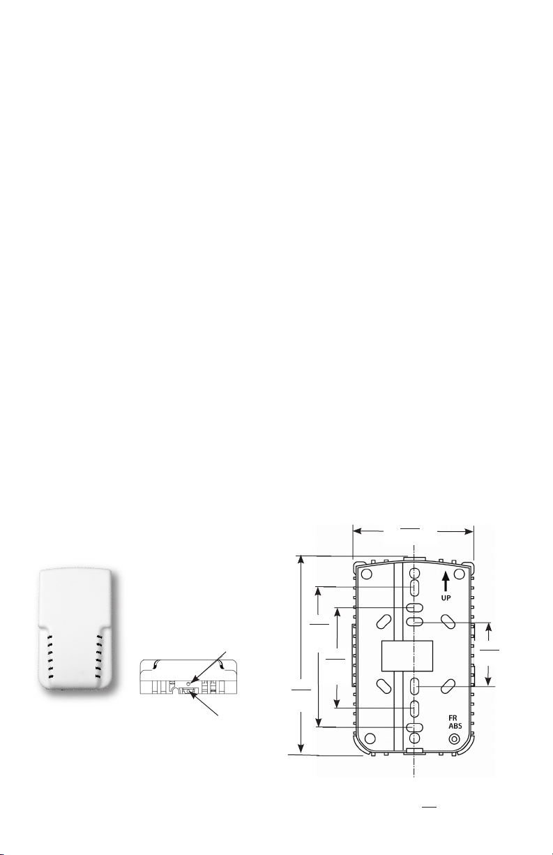
Model SRH
Wall Mount Unit
Top View
Security Screw
Security Latch
Front View
To open wall unit, back out the
security set screw (if used), then
press the security latch inward and
lift-up cover.
1
4.69
119
71.50
3.30
84
2.37
60
Wall Mount - Back Plate
2.81
1.41
36
in.
mm
Page 2
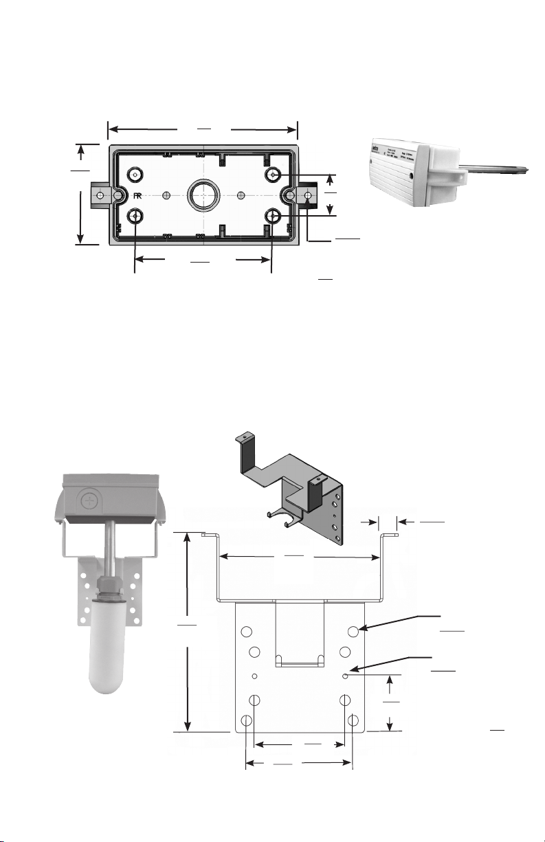
2.2 Duct Mount
For proper operation, it is necessary to locate the transmitter in the center of a section of duct
that receives adequate air flow. Conversely, it must be free of fans, corners, heating/cooling
coils, or any other equipment/ environmentals that could adversely affect relative humidity
measurement.
2.69
68
Duct Mount Base
5.1
130
3.72
94
1.11
28
in.
mm
X2
0.180
5
Model SRH
Duct Unit
shown w/sensing probe
Insert sensing probe through hole (5/8” dia. minimum) and attach full assembly via
the two mounting holes on each side.
2.3 Outside Air Mount
The outside air configuration is supplied with a mounting bracket and two 10-16 x 1/2’ hex
head screws. Locate a position on the building that is clear of exhaust ducts, high exposure
to the sun, direct rain, or other outdoor factors that could adversely affect the operation of
the unit. Ideally, a sheltered area (under an eave) on the north side of the building is best to
protect from the above effects.
Model SRH
Outside Air Unit
shown w/Porous Weather
Shield
4.05
103
5.00
127
1.75
44
2.81
71
3.31
84
Outside Air Mounting Plate
2
X2
0.550
14
X8
0.325
8.3
X2
0.154
4
in.
mm
Page 3
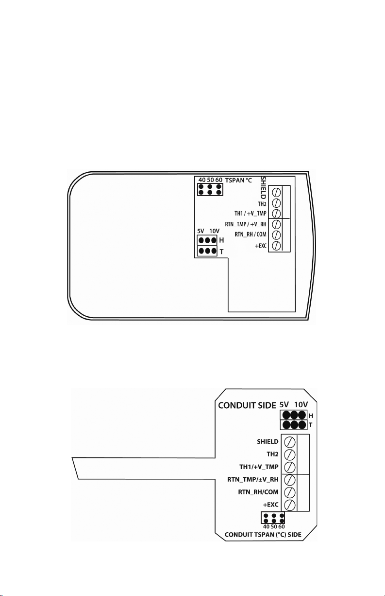
3.0 ELECTRICAL INSTALLATION
3.1 Wiring
Match your transmitter with the corresponding diagrams and set the jumpers and wire
accordingly. Ensure that all of the installation and wiring is in compliance with all national
and local codes. Use 18-22 AWG shielded, twisted pair, copper conductors.
Caution: Do not bundle transmitter wires with AC power wires. Shield must be connected to
earth ground for CE compliance.
Wall Mount
Connector/Jumper Locations - Inside cover
Duct and Outside Mount
Connector/Jumper Locations - Board Assembly/Duct Probe
3
Page 4
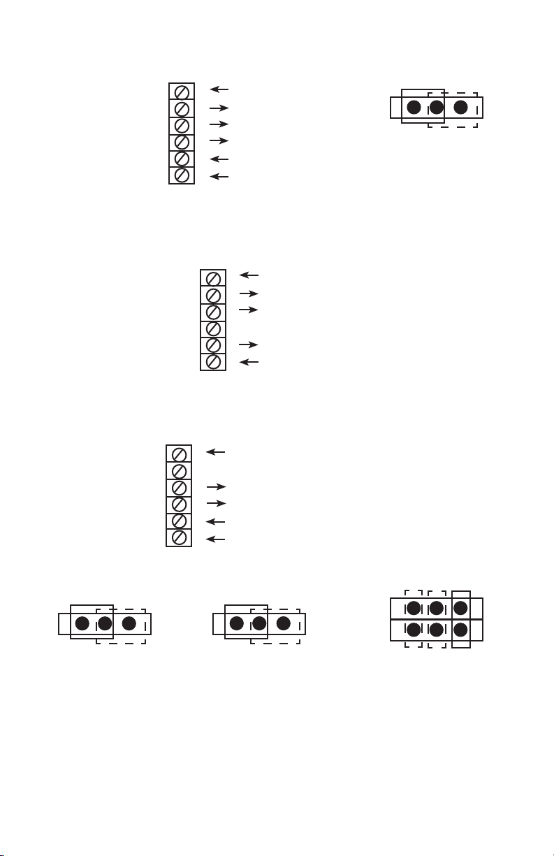
Wiring 0-5 V/0-10 V Output Units (3-wire / T0, T1 & T2)
Shield
TH2
TH1 / +V_TMP
RTN_TMP/ +V_RH
RTN_RH / COM
+EXC
Note: Unit shipped in 0 to 5V Mode. Move jumper to right for 0 to 10V Operation
Wiring 4 to 20 mA Output Units (2-wire / T0, T1 & T2)
6 Earth Ground Connection
5
Thermistor/PRTD
4
3 RH (0 to 5V/0 to 10V) Output
2 Ground
1 Vin
Selectable Outputs
5V
10 V
H
Shield
TH2
TH1 / +V_TMP
RTN_TMP / +V_RH
RTN_RH / COM
+EXC
Wiring 0-5 V/0-10 V Output Units (4-wire / T3 & T5)
Shield
TH2
TH1 / +V_TMP
RTN_TMP/ +V_RH
RTN_RH / COM
+EXC
Selectable Outputs
5V
10 V
H
6 Earth Ground Connection
5
Thermistor/PRTD
4
3 NC
2 RH (4 to 20 mA) Output
1 Vin
6 Earth Ground Connection
5
NC
4
Active Tmp (0-5V/0-10V )Output
3 RH (0 to 5V/0 to 10V) Output
2 Ground
1 Vin
Selectable Tspan
5V
10 V
T
40
50
60
(°C)
Note: Unit shipped in 0 to 5V mode with Tspan set to 60°C. Move Tspan jumper to select
optional ranges.
4
Page 5

Wiring 4 to 20 mA Output Units (3-wire / T3, T5)
Selectable Tspan
Shield
TH2
TH1 / +V_TMP
RTN_TMP / +V_RH
RTN_RH / COM
+EXC
Note: Unit shipped with Tspan set to 60°C. Move Tspan jumper to select optional ranges.
6 Earth Ground Connection
N/C
5
N/C
4
3 Active TMP (4-20 mA) Output
2 RH (4 to 20 mA) Output
1 Vin
40 50
60
(°C)
5
Page 6

4.0 CALIBRATION
All relative humidity products are fully tested and calibrated prior to shipment in
accordance with the National Institute of Standards and Technology (NIST), the
highest quality standard available.
Once installed in the field, no calibration of the units is required. Instead, this
product suite features field-replaceable sensor modules that allow the end user
to replace the sensors on-site. This eliminates time consuming and costly factory
calibration, while reducing downtime during service intervals. Additionally, the
duct mount probe is easily accessed by taking off the front cover, removing the
sensor board assembly, and replacing the sensor module on the tip of the sensor
board. This further contributes to a more user-friendly, lower cost product line
that is focused on customer needs and ease of use.
4.1 Remove/Install the Sensor Tip
Note: Power Must be removed from the main PCBA prior to replacing the sensor
tip module. Failure to comply could possibly damage the sensor tip module
Wall Mount
White
Retaining Clip
Outdoor and Duct Mount
6
Page 7

Replaceable Sensor with Sintered Filter
White
Retaining Clip
Top View
Side View
(PCB to PCB)
Remove the white retaining clip (shown above and on page 6). Remove the
sensor tip module by holdng the sides of the sintered filter along the pcb edges.
Then gently pull the sensor tip module out of the mating connector. Gently push
the replacement sensor tip module into the mating connector (as shown) and
replace the retaining clip to secure the connection.
4.2 Ordering Information - Replacement Sensor Assembly*
Example: Order Part No. SRH3-2P-T0 = Sensor Assembly with 2% accuracy, RH only.
S R H 3
Model Accuracy Temperature Outputs
SRH3 = SRH 2P = 2% T0 = None (RH only)
T3 = -50°C to 60°C (active)
T5
3P = 3% T1 = 10KΩ NTC (passive)
5P = 5%** T2 = 1000Ω RTD (passive)
= -10°C to 60°C (active)
*SRH1 units originally ordered with either a T3 or T5 temperature option MUST
be replaced with the same T(x) version.
**Not available with T3 or T5 option.
7
Page 8

5.0 SPECIFICATIONS
RH Performance Data
Sensing Element Capacitive Polymer
Humidity Operating Range 0 to 99% RH (non-condensing)
Accuracy at 68°F (20°C) 2%, 3%, 5%
Hysteresis <1.5%
Repeatability <0.5%
Long Term Stability <1%/year @ 68°F (20°C), 50% RH
Electrical Data
Signal Outputs
Current (2-wire ckt.) 4 to 20 mA
Field Selectable Voltage (3-wire ckt.) 0 to 5 VDC, 0 to 10 VDC
Excitation
0 to 10 VDC 13.5 to 30 VDC
0 to 5 VDC, 4 to 20 mA 12 to 30 VDC
Maximum Load (Current only) Ω = (Supply - 10) / 0.02
Electrical Termination Pluggable Terminal Block (5mm Pitch)
Wiring Protection Reverse Excitation
CE Compliance EMC Directive 2004/108/EC
Temperature Sensing Options (Passive)
T1 Thermistor Output NTC 10K Ω @ 77°F/25°C (Direct Connect)
Type II
T2 RTD Output 1000 Ω @ 32°F/0°C (Direct Connect)
385 Platinum Curve
Temperature Sensing Options (Active)
Signal Ouput Options (includes humidity output):
Current 4 to 20 mA
Field Selectable Voltage 0 to 5 VDC, 0 to 10 VDC
Available Ranges: Accuracy:
T3 (-50°C to 60°C) ±0.6°C (20°C @ 50%)
T5 (-10°C to 60°C) ±0.4°C (20°C @ 50%)
Environmental Data
Operating Temperature °F (°C) -40 to 140 (-40 to 60)
Storage Temperature °F (°C) -40 to 158 (-40 to 70)
Moisture Resistance IP65, NEMA-4 (Duct & Outside Air)
Solar UV Resistance (Outside Air)
Flammability Rating 94-V0
Compliance RoHS and CE Compliant
Physical Description
Enclosure
Wall Mount ABS 94-V0
Duct & Outside Air Poly Carbonate 94-V0
Probe (Duct & Outside Air) Aluminum
Weather Shield (Outside Air) Porous Polyethylene
8
Page 9

6.0 DIMENSIONAL DRAWINGS
2.81
71.50
5.10
129.5
5.60
142.2
2.68
68.1
4.69
119
0.98
24.7
Wall Mount
6.10
154.9
Security Latch
2.38
60.4
4.50
114.4
2.38
60.4
2.68
68
8,7
221
Duct Probe (5/8” dia.)
Duct Mount
4.04
102.6
12.52
318
4.05
102.7
Duct mount
shown w/optional
Duct Flange
in.
mm
Outside air
9
Page 10

7.0 DUCT MOUNT INSTALLATION
P/N 888415
2.25
57.15
1.125
28.58
1.50
38.10
2.25
57.15
3.00
76.20
Optional Duct Flange
(Top View)
10
4x
ø.180
4.57
1.75
44.45
in.
mm
Page 11

1.62
41.25
Conduit Hole
1.125
28.5
dia.
Optional Duct Flange
0.68
17.27
in.
mm
(Side View)
Mounting the transmitter using the optional duct flange.
1. Drill a 1.125” (28.5 mm) diameter hole into the duct
2. Insert the tapered bushing side into the conduit hole.
3. Press in and all around the outer exposed edge of bushing so the bushing
groove captures the inside edge of the conduit.
4. Secure flange using #10-16 x 1/2” self-drilling screws (recommended)
5. Insert duct probe to desired length plus 1/2”. Pull back unit approximately 1/2”
to create seal.
Note: To remove, simply twist duct housing side to side while pulling outward.
11
Page 12

8.0 RETURNING PRODUCTS FOR REPAIR
When returning a product to Setra Systems, the material should be carefully
packaged and shipped prepaid to:
Setra Systems, Inc.
159 Swanson Road
Boxborough, MA 01719-1304
Attn: Repair Department
To assure prompt handling, please refer to return instructions on our Web site
at http://www.setra.com/tra/repairs/cal_rep.htm.
9.0 WARRANTY AND LIMITATION OF LIABILITY
SETRA warrants its products to be free from defects in materials and workmanship, subject to the
following terms and conditions: Without charge, SETRA will repair or replace products found to be
defective in materials or workmanship within the warranty period; provided that:
a) the product has not been subjected to abuse, neglect, accident, incorrect wiring not our own,
improper installation or servicing, or use in violation of instructions furnished by SETRA;
b) the product has not been repaired or altered by anyone except SETRA or its authorized service
agencies;
c) the serial number or date code has not been removed, defaced, or otherwise changed; and
d) examination discloses, in the judgment of SETRA, the defect in materials or workmanship developed under normal installation, use and service;
e) SETRA is notified in advance of and the product is returned to SETRA transportation prepaid.
Unless otherwise specified in a manual or warranty card, or agreed to in writing and signed by a
SETRA officer, SETRA pressure, humidity, and acceleration products shall be warranted for one year
from date of sale.
The foregoing warranty is in lieu of all warranties, express, implied or statutory, including but not
limited to, any implied warranty of merchantability for a particular purpose.
SETRA’s liability for breach of warranty is limited to repair or replacement, or if the goods cannot be
repaired or replaced, to a refund of the purchase price. In no instance shall SETRA be liable for incidental or consequential damages arising from a breach of warranty, or from the use or installation
of its products. No representative or person is authorized to give any warranty other than as set out
above or to assume for SETRA any other liability in connection with the sale of its products.
For all CE technical questions, contact Setra Systems, USA. EU customers may contact our EU
representative Hengstler GmbH, Uhlandstr 49, 78554 Aldingen, Germany (Tel: +49-7424-890; Fax:
+49-7424-89500).
159 Swanson Road, Boxborough, MA 01719-1304
Tel: 800-257-3872/978-263-1400
Email: sales@setra.com; Web: www.setra.com
SS-SRH Rev. B 2/25/2010
12
 Loading...