

Page 1
Model SRCM
Operation
Page 2

Table of Contents
Operation …………………………………………………………………………………………1
Home Screen ……………………………………………………………………………………2
Condition banner …………………………………………………………………………………2
Condition Banner— Touch-Screen Operation ………………………………………3
Operating Condition Screen …………………………………………………………4
Pressure Value ………………………………………………………………………5
Slider Bar and Setpoint Values ………………………………………………………5
Slider Bar On/Off ……………………………………………………………………6
Occupied and Standby Modes …………………………………………………………6
Menu Screens …………………………………………………………………………7
Setup Unit ………………………………………………………………………………………8
Primary Room …………………………………………………………………………8
Secondary Room ……………………………………………………………………8
ROOM - Primary or Secondary ………………………………………………………8
Primary Analog Output ………………………………………………………………9
Engineering Unit ………………………………………………………………………9
Sensor Range ………………………………………………………………………… 9
Changing Room Name …………………………………………………………… 10
Setup Display ………………………………………………………………………………… 11
General Tab— Customizing the Condition Banner ………………………………… 11
Advanced Tab— Customizing the Operating Condition Screen ………………… 12
Display Averaging (tenths of seconds …………………………………………… 12
What Pressure To Display ……………………………………………………… 12
Supervisor and Operator Passwords …………………………………………… 13
Condition Banner Tab—Customizing Blinking Screens …………………………… 14
Setup Alarm ………………………………………………………………………………… 15
Alarm Set Point ……………………………………………………………………………… 17
Channel For BMS—Switching Room Pressure …………………………………… 17
Alarm Matrix. ………………………………………………………………………………… 18
Calibration and Self-Test …………………………………………………………………… 20
System Information ………………………………………………………………………… 22
USB Configuration Cloning ………………………………………………………………… 23
Returning Product for Repair ………………………………………………………………… 28
Warranty and Limitation of Liability ………………………………………………………… 28
Page 3

Page 4
Operation
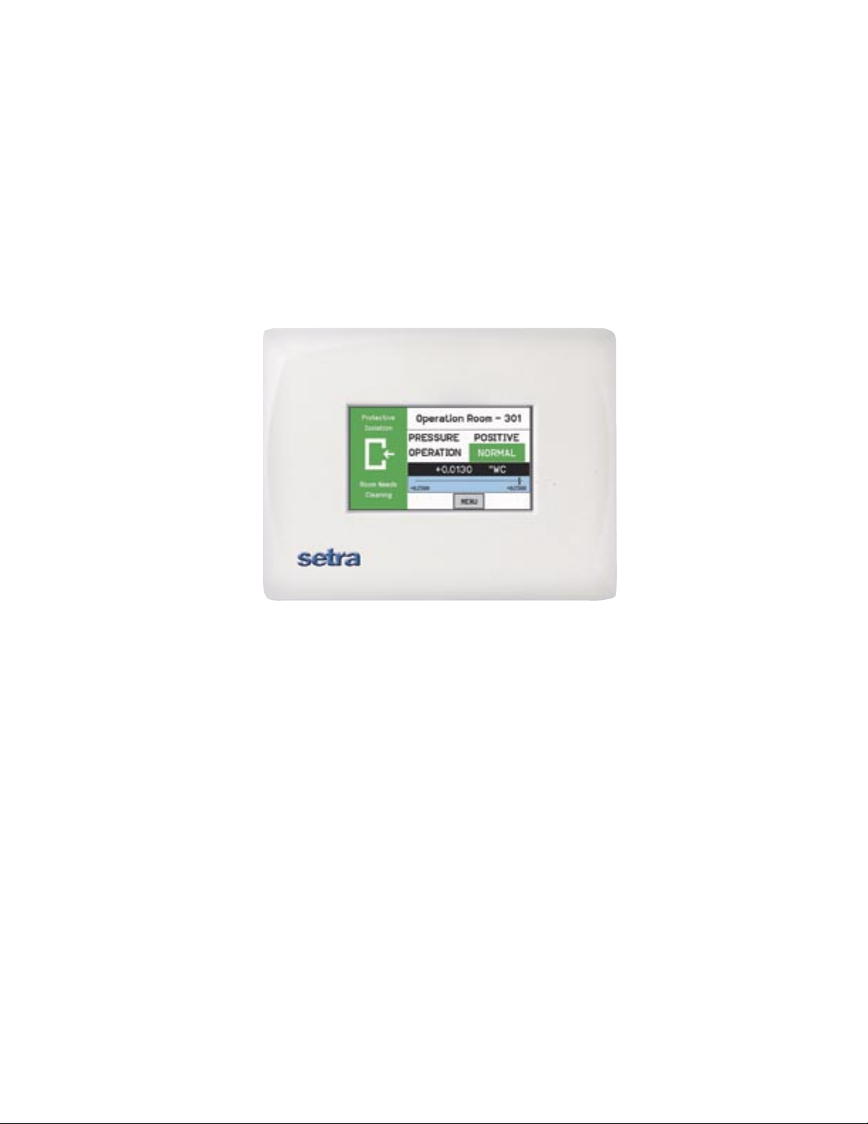
The following pages describe how to operate the SRCM using the touch-screen interface.
The screen has two basic functions. The primary mode of operation displays the Home
screen, which shows the end-user pressure values, messages, text, and other data intended
for visual pressure verification in the facility. The second mode of operation is the Administrative Menu (Menu) screen, which permits setup, configuration, and changes to
how the SRCM operates. After changes have been performed on the Menu screen, functions are saved and operation returns to the Home screen.
Home Screen
Menu Screen
-1-
Page 5
Condition Banner
Pressure Value
Condition Banner
Home Screen
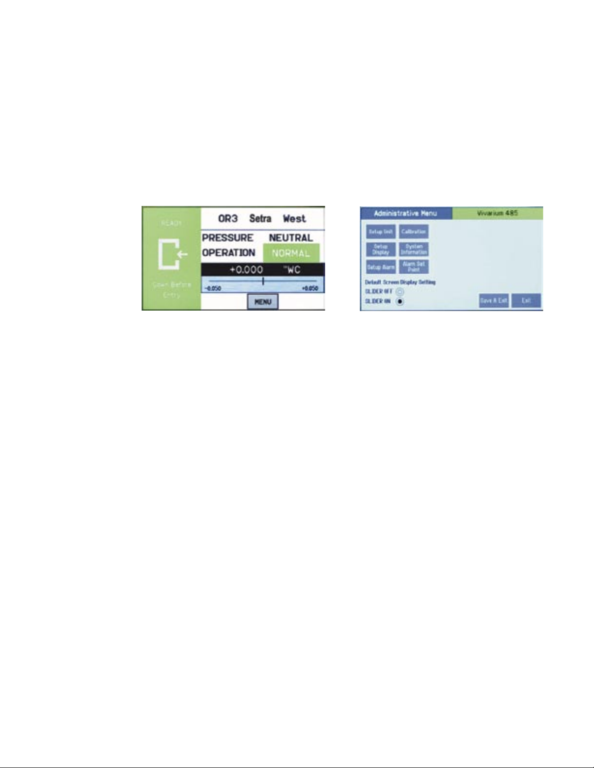
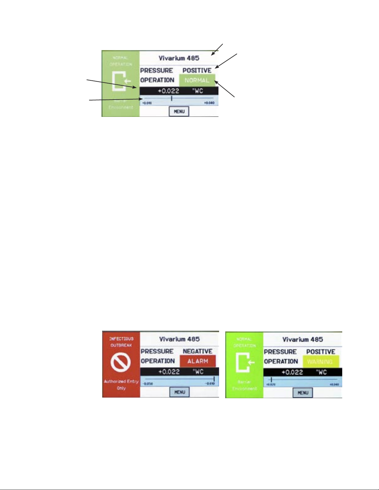
The Home screen is the normal continuous operating mode of the SRCM. The Home
screen shows a Condition Banner on the left one-third of the screen, and Operating Conditions on the right two-thirds of the screen.
Slider Bar and Setpoint Values
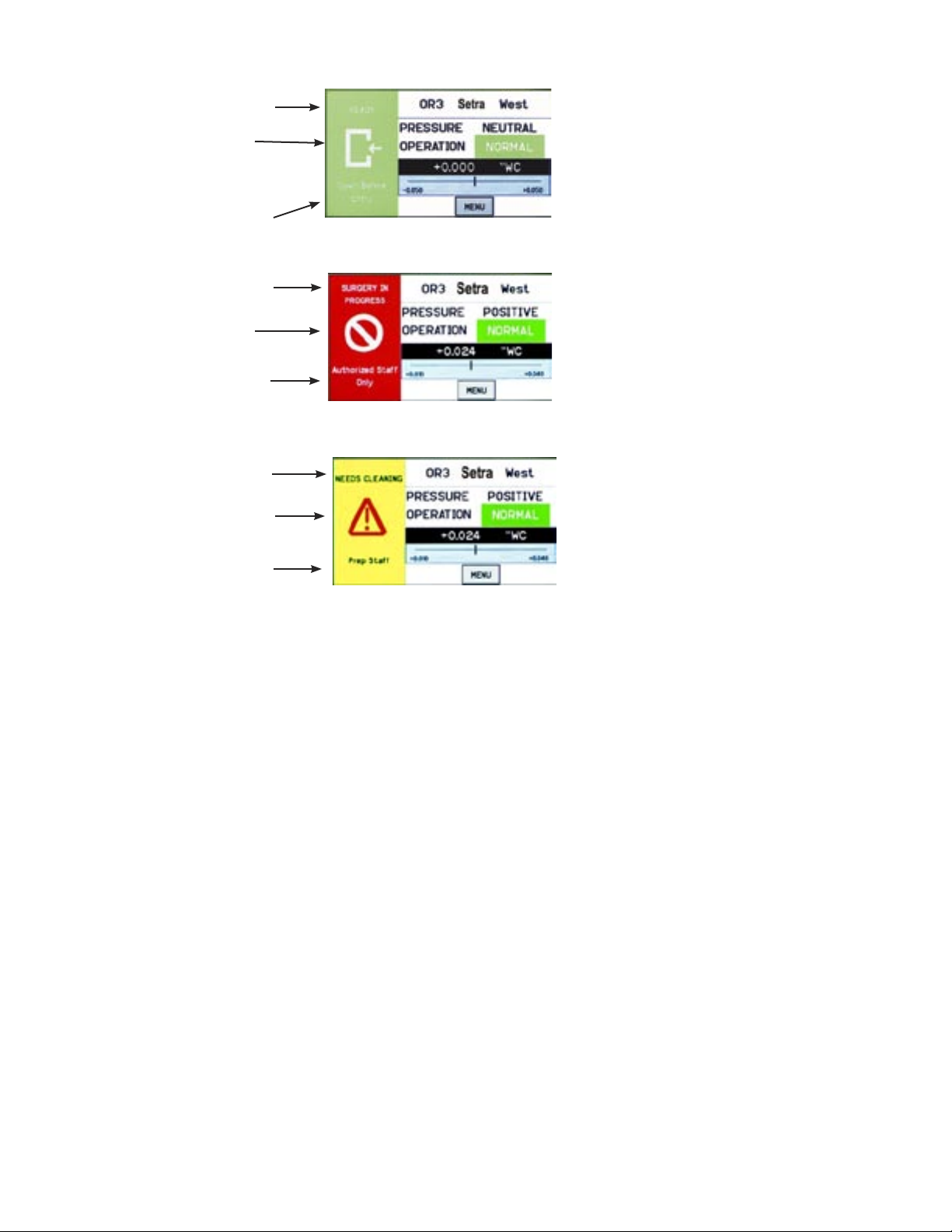
The Condition Banner is a screen that can be configured by the end-user or facility
manager to display a message to staff on the floor. The Condition Banner can be Green,
Yellow, or Red, depending on the type of message desired.
The Condition Banner does not affect or respond to pressure in the space. Banner screens
are only messages intended to be communicated to staff, personnel, and other people outside the room. The banner does not change color for any alarms, warnings, or changing
conditions of the space. The banner may be changed manually, as required, by pressing
the touch-screen anywhere within the banner color region.
Room Label
Pressure Mode
• Positive
• Negative
• Neutral (span)
• Standby
Operation
• Normal (green)
• Warning (yellow)
• Door (yellow)
• Alarm (red)
-2-
Page 6
User defined text
ENTRY PERMITTED
graphic (arrow is not intended
to indicate direction of airflow)
User defined text
Green Condition Banner—shows Entry Permitted graphic, and user defined
text above and below graphic image.
Use the GREEN banner to indicate
room is safe to enter.
User defined text
STOP graphic
User defined text
User defined text
Warning graphic
User defined text
Condition Banner –
Touch Screen
Operation
Red Condition Banner—shows
Stop graphic, and user defined text
above and below graphic image.
Use the RED banner to indicate
room is under critical use and entry
Yellow Condition Banner—shows
Warning graphic, and user defined text
above and below graphic image. Use
the YELLOW banner to indicate room
is under transient use and entry is restricted.
Once the messages of each of the three Condition Banners are defined in the
Menu section, the user can cycle through all three conditions by simply touching
the left one-third of the screen in any region. If passwords are enabled, the user
will be prompted to enter their password before proceeding. Each of the three colored screens can have a unique message defined. See Section: Setup Display, page
11, for instructions on how to setup the Condition Banner.
When the Operating mode of the SRCM is set for PRESSURE = STANDBY, the
top part of all three banners will display STANDBY to indicate that active use of
the SRCM has been suspended and no alarms will occur. See Section, Setup Display, page 11, for more information on STANDBY mode.
-3-
Page 7
Operating Condition
Screen
Pressure Value
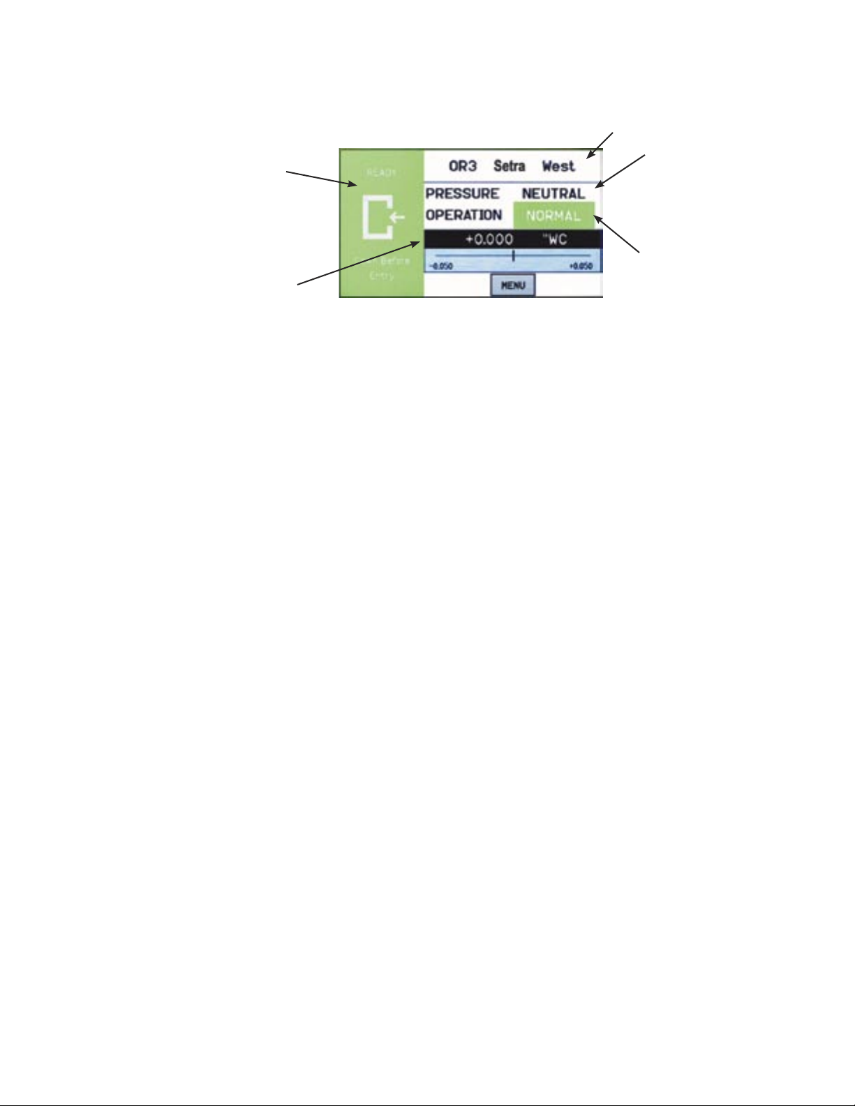
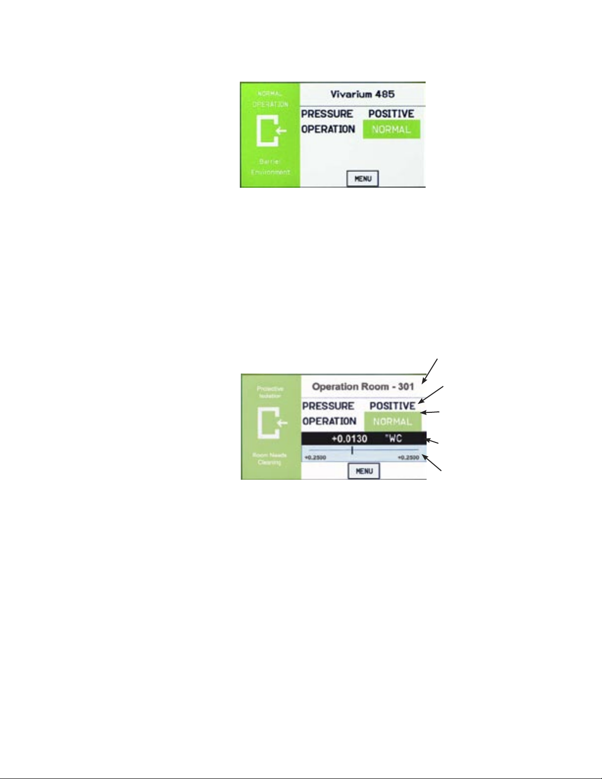
The Operating Condition screen shows the user the active operating conditions of the
pressurized space.
Room Label
Pressure Mode
• Positive
• Negative
• Neutral (span)
• Standby
Slider Bar and
AlarmSetpoint
Values
Operation
• Normal (green)
• Warning (yellow)
• Door (yellow)
• Alarm (red)
The Room Label at the top of the screen can be defined by the user to ensure the
viewer understands which room is actively being monitored by the SRCM. See Section, Setup Display, page 10, to enter text for your specific room.
The PRESSURE indication shows the intended direction of airflow for the space.
POSITIVE for airflow out of the space, NEGATIVE for airflow into the space, NEUTRAL for airflow conditions that may vary, and STANDBY for use when there is no
need to verify the direction of airflow (alarms are disabled).
The OPERATION indication shows whether the pressurized space is within normal operating parameters (within alarm thresholds), or whether there is an alarm or
warning condition. If operation is within alarm thresholds, a green NORMAL indication is shown. If operation is near either high or low alarm threshold limits, a yellow
WARNING indication is shown.
If operation is at or beyond high or low threshold limits, a red ALARM indication is
shown. If Audible Alarming is Enabled, a piezo buzzer will sound and a SILENCE
menu button will appear. Pressing the SILENCE button will shut off the alarm for
the period of time defined in the alarm configuration. Alarm operation can be configured to blink or sound an audible signal. See Section, Alarm Setup, page 15, for more
about setting up ALARM and WARNING conditions
In addition to pressure indication, OPERATION also displays whether a door is open.
If a door switch is configured, an open door contact will display a yellow DOOR
indication.
-4-
Page 8
Pressure Value
Slider Bar and
Setpoint Values
Pressure Value
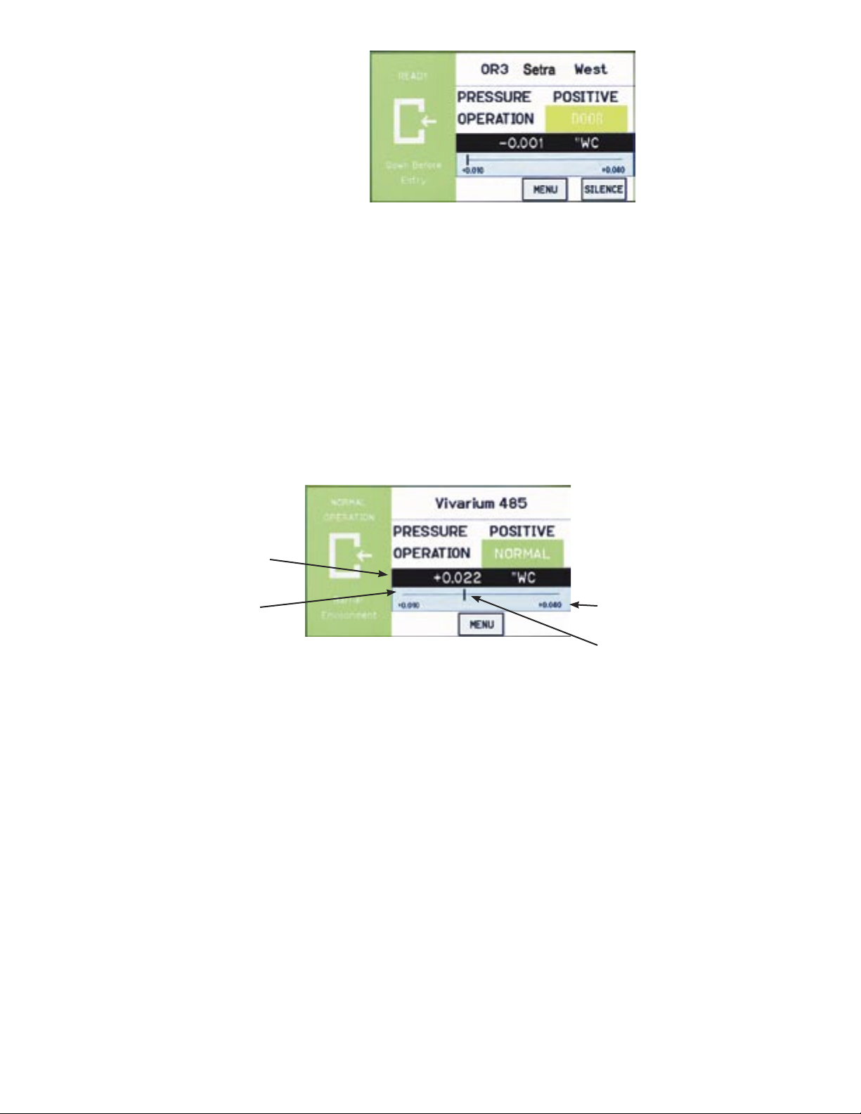
A black banner displays the actual pressure reading from the space, in either
Water Column inches (“ WC) or Pascals (Pa). The resolution of display can
vary, depending on desired configuration; either 2, 3, or 4 significant digits. The
accuracy of measurement remains the same regardless of the number of digits
displayed.
The blue banner below the pressure value shows where the current pressure
reading is in relation to alarm setpoints. The value at the left of the blue banner
is the low setpoint value, and the value on the right is the high setpoint value.
The middle “Cursor” represents the curremt measured pressure value.
.
Slider Bar and
Setpoint Values
High alarm setpoint
“Cursor” representing where
the pressure value lies relative
to the alarm setpoint
-5-
Page 9
Slide Bar On/Off
If the user does not wish to see the actual pressure value or slider bar, it can be turned
off using the Menu screen. Operation of the pressure sensing and alarming is unaffected. See Section, Menu Screens, page 7 .
Occupied and
Standby Modes
By pressing the touch-screen directly on the word POSITIVE (or NEGATIVE, NEUTRAL, or STANDBY), the user is able to change the condition of the room between
OCCUPIED and STANDBY modes. A pop-up menu appears to enable selection. If
passwords are enabled, the user must first enter a password to proceed with the change.
In OCCUPIED mode, the full function of the SRCM is active. In STANDBY mode, the
SRCM will perform all functions except that alarming will be disabled (both audible
and visual alarms). The STANDBY mode is designed to put the SRCM into a mode
where room pressurization is not critical, such as cleaning, patient transfer, or longerterm unoccupied status.
Room Label
Mode, Touch Sensitive
Room Status
Pressure Display
Pressure vs. setpoint
slide bar
-6-
Page 10

Menu Screens
Pressing the MENU button on the Home screen brings up the Administrative
Menu (Menu). If passwords are enabled, the user is required to enter the correct
password before being authorized to make changes. From the Administrative
Menu, the user can set all operating parameters of the SRCM. This includes
initial setup, commissioning, calibration, customizing the displays, and warning
and alarm parameters.
Calibration*—used to re-zero
or calibrate internal sensor
Setup Unit—for initial unit setup
Setup Display—customizes the display
Setup Alarm—setup the behavior
of how alarms are communicated
to the user
Slider ON/OFF—defines whether the
pressure value and alarm setpoints are
displayed on the home screen
* Calibration is only required for highly accurate measurement needs such as
those needed to comply with federally mandated regulations. See the SRCM
Product Data Sheet for more information.
Room Label that settings
apply to (global unless
Secondary is shown)
Serial number and other
system information
Alarm setpoint values
Save Settings and Exit
-7-
Page 11

Setup Unit
Upon initial installation, the Setup Unit screen should be used to define installation
parameters specific to the job site.
The SRCM can take as input, the signal from two separate pressure transducers. These
are configured for either Primary Room or Secondary Room (an anteroom is an example of a secondary room). When two transducers are used, the Home screen display of
the SRCM can toggle between each space to indicate the status of each room momentarily, cycling from one to the other a few seconds apart.
Primary Room sensor:
• OnBoard Sensor
• External Ch1
Secondary Room sensor:
• External Ch1*
• External Ch2
Setup selection to configure
either Primary or Secondary
Room
Pressure signal output (AO)
scale and units:
• 4-20 mA
• 0-5 Vdc
• 0-10 Vdc
*If Ch1 is selected for the Primary room, it will not be an available option for the
Secondary room.
Primary Room
Sensor
Change, if necessary, to match sensor being used. OnBoard is the default, which uses
the sensor manufactured on-board the unit. Alternatively, an external sensor (also
known as “external transducer” such as a Setra 264 or Setra 267) may be used. If an
external sensor is used, change this selection to Analog Ch1. The FS output and range
of the external sensor will need to be entered.
Secondary Room
Sensor
Change, if necessary, to match sensor being used, if there is one present. None is the
default. An external sensor (also known as “external transducer” such as a Setra 264 or
Setra 267) may be used for the secondary room, or anteroom. If an external sensor is
used, change this selection to Analog Ch1. The FS output and range of the external sensor will need to be entered.
Room label of selected room,
either Primary or Secondary
depending on ROOM radio
button
Full Scale (FS) range of
transducer selected, Primary
or Secondary
Pressure units, either “ WC or Pa
ROOM - Primary
Secondary
Use the radio button to select the setup parameters for either the Primary Room or
Secondary Room.
-8-
Page 12

Primary Analog
Output
This Analog Output (AO) is used to communicate the value of the differential
pressure to an external source such as a Building Management System (BMS).
The value is scaled as either 4-20 mA, 0-5 Vdc, or 0-10 Vdc, selectable. A normalized pressure value is generated once every 100 milliseconds. The analog
output is only available for the Primary room.
Engineering Unit
Sensor Range
If selecting Analog Ch1 or Analog
Ch2 for either Primary of Secondary
Room, enter full-scale (FS) range
that matches the transducer being
used
Units of measurement to show on the Home screen, selectable as either inches
of Water Column (“WC) or Pascals (Pa).
The SRCM is manufactured with an on-board differential pressure transducer.
This transducer is manufactured to specifications for fixed minimum and
maximum pressure measurement, known as the full-scale range of the transducer. When the on-board transducer is used exclusively, these values cannot
change. Alarm setpoints cannot be set above the positive value or below the
negative value. If a wider or narrower sensor range is required for the project,
an external pressure transducer such as a Setra 264 or Setra 267 may be chosen
to match the requirements. See more above under Primary Room or Secondary
Room.
If an external transducer is used, the full-scale values and other parameters need
to be configured into the SRCM so the unit understands the scale of measure-
Also enter voltage or milliamp
range that matches the transducer
being used
Select desired units of measure to display on the Home
screen, either “WC or Pa.
The unit of measure for the
external transducer must be
selected before entering range
and output of the unit. After
entering all data the units may
be changed and the range will
scale accordingly.
-9-
Page 13

Changing Room Name
ment being received on the inputs Analog Ch1 or Analog Ch2.
The room name shown on the top part of the Home screen is changed
using the Room Label button. The Room Name entry box appears in the
middle of the Setup Unit display. Depending on whether the Primary or
Secondary ROOM radio button is enabled, the matching Room Name
entry box appears.
Press anywhere in the Room Name selection box to bring up the onscreen keyboard to enter the room label text desired. Be sure to press the
Save button under the text entered before leaving this screen.
Touch anywhere within the
Room Name entry box to bring
up the on-screen keyboard and
enter text.
Data Entry screen with
QWERTY keyboard
Use CAP-ON button to switch between
lower-case and upper-case lettering and
other characters
Press Save after text entry is
complete.
When finished with data entry, select Enter to
confirm, or ESC to cancel and return to the
previous screen
-10-
Page 14

Setup Display
The Setup Display screen permits authorized users (based on password level) to
configure Condition Banner messages and other Home screen options. There are
three tabs for display customization; General, Advanced, and Condition Banner.
General Tab–
Customizing the
Condition Banner
Change color and text
of Condition Banner by
pressing anywhere in the
colored region
The General tab allows the user to define messages for each Condition Banner
color. Pressing anywhere in the colored region of the Condition Banner changes
each selection between GREEN, YELLOW, and RED. By pressing on the colored region of text, the on-screen keyboard pops up, enabling data entry. If User
Defined Text is Disabled, then data entry on the Condition Banner will not be
permitted.
Configure whether the user can
change the text of the Condition
Banner. Enabled or Disabled
Room Status. Occupied or Standby
When finished making changes, press Save & Exit to store
the modifications. Or press
Exit to discard changes and
return to the previous screen.
-11-
Page 15

Advanced Tab–
Customizing the Operation Condition Screen
Primary Pressure Resolution
The number of significant digits
displayed for the pressure value
Define Supervisor and Operator
passwords. Enable or Disable
use of passwords
The Advanced tab allows the user to make refinements in how information is displayed on the Operating Condition section of the Home screen.
The display contrast level is adjusted using Adjust Contrast Level, with
selections from 1-4. After modifying this parameter, press Save & Exit to
view the brightness and contrast on the Home screen display. Depending
on the lighting and viewing conditions in the final space, different contrast levels can improve readability of the SRCM.
Contrast level of Home
screen. Adjust from 1-4
for readability in varying
lighting conditions
Display Averaging.
Select a value from 1-40
What Pressure To Display:
• Primary Only
• Secondary Only
• Toggle
When finished making changes, press Save & Exit to store
the modifications. Or press Exit to discard changes and return
to the previous screen
Display Averaging (tenths of seconds)
This function is used to improve the stability of the pressure value displayed on the Home screen, so significant digits do not change rapidly.
It is used more often in environments where the user requires higher
display resolution (4 digits) but the ambient pressure is unstable. By increasing the number, the effective number of measured data points is increased and a weighted average is developed. Input the number in tenths
of a second for the response time of the display to a pressure change.
There is no ratcheting of the display or a deadband. The pressure change
is very smooth. For example, entering 10 equates to the display reaching
final value in 1 second. Entering 2 equates to final value in 200 ms.
Display Averaging does not affect the Analog Output response time, only
the apparent stability of the pressure display. Display Averaging also
does not affect Alarm Thresholds or Alarm Delay.
What Pressure To Display
This function defines what pressure value is shown on the Home screen
under normal operating conditions. This can be Primary Only, Secondary
Only, or Toggle, depending on what room is most important for visual
pressure verification.
If this is set to Primary Only, then the Home screen will show the pressure value read by the primary pressure transducer (either on-board, or
the alternate primary transducer configured from a separate transducer, if
one is used).
-12-
Page 16

If a secondary transducer is in use, and an alarm condition occurs in the secondary room, the display will toggle and remain on the secondary room and pressure value as long as the alarm condition is present in that space.
If this is set to Secondary Only, then the Home screen will show the pressure
value read by the secondary pressure transducer (anteroom for example). In this
case, if an alarm condition occurs in the primary room, the display will toggle
and remain on the primary room and pressure value as long as the alarm condition is present in that space. If no Secondary Room is configured on the Setup
Unit screen, attempts to choose Secondary Only will result in the error “Secondary room source is NONE.”
If this is set to Toggle, then the Home screen will show the pressure value read
by both transducers, alternating back and forth momentarily. If an alarm condition occurs in either room, the display will toggle to the appropriate room and
pressure value and remain on that room as long as the alarm condition is present. If both rooms are in alarm, then the alarm condition and pressure values
will toggle
Supervisor and Operator Passwords
The password function provides security against changed configurations by unauthorized users. This is accomplished by using two levels of password protection. These can be enabled or disabled.
The Operator level allows access to change between Occupied and Standby
room modes, but no other changes.
The Operator is the person that has day-to-day interaction with the monitor to
change operating modes from Occupied mode to Standby (where no alarms are
active), the operator can also respond to local audible and visual alarms. This
can be a Nurse or a Lab Technician. The SRCM was designed to make interaction with the unit as easy as possible for the Operator. Changes to messages and
to the room mode requires simply touching active areas of the display. If Operator Password is enabled then a password will be needed before the change can
be made.
The Supervisor Level allows full access to all menus. The Supervisor has access
to all levels of the menu structure. This mode is used during initial configuration
and follow-on reconfiguration.
NOTE: The master Supervisor password is 351, and will work for any
condition where a user may need to reset passwords.
-13-
Page 17

Condition Banner TabCustomizing Blinking
Screens
The Condition Banner tab allows the user to choose whether certain parts of the
screen blink or not. Blinking components on the Home screen are intended to
draw more attention to the Condition Banner or the OPERATION indicators, for
the purpose of making exception conditions more noticeable to staff concerned
with room pressurization status.
Alarm Blink Defines the behavior of the red
ALARM indicator on the Home
screen. Normal Blink is used for
the green NORMAL indicator.
Warning Blink Applies to the yellow WARNING,
DOOR indicator.
Blink in Red/Green/Yellow Applies to the Condition Banner
messages and icon on the left onethird of the Home screen.
Save & Exit Saves the selections made on this
screen.
-14-
Page 18

Setup Alarm
The Setup Alarm screen permits authorized users (based on password level) to
configure alarm behavior, such as the duration of alarms, methods of clearing
alarm condition, and how alarms are acknowledged.
Define which room the
Setup Alarm conditions will
apply to
For each room (Primary or
Secondary), define whether
the room pressure will be
Positive, Neutral, or Negative
Latch Alarm If enabled, causes the display of red ALARM on the
Home screen to remain, even if room pressurization
returns to NORMAL. Latch Alarm enabled requires that
an alarm event be acknowledged and that the pressure
returns to within the normal range. This is useful because it forces recognition that an alarm event occurred.
The alarm will still be on even if the pressure returns to
normal range. Only when the alarm is acknowledged will
alarming cease. When disabled, the alarm will be silenced
when the pressure returns to normal range without requiring acknowledgement.
When a Latch Alarm occurs, the Home screen displays a
RESET button to the right of the Menu button. Press the
RESET button to acknowledge and reset the Latch Alarm
condition.
Alarm Delay Time between when the pressure went outside alarm
setpoints and when the unit goes into alarm mode. This is
useful in preventing false alarms. For example, if Alarm
Delay is set to 20 seconds, the staff has 20 seconds to
open a door, enter the room and close the door before
the alarm sounds (if audible alarms are enabled). Alarm
Delay also applies to alarms annunciated to a remote annunciator via the SRCM Digital Output (hardware configuration).
-15-
Page 19

Audible Alarm Enables or disables the audible buzzer. Regardless of
whether audible alarming is enabled or disabled, the red
ALARM condition will show on the Home screen, annunciate to an SRAN, and propagate to a configured Digital
Output. If an alarm occurs and the audible alarm is enabled, a new SILENCE button will appear on the Home
screen so that the operator can silence the audible alarm.
The audible alarm is silenced only for the period of time
defined by Mute Time Out.
Mute Time Out Sets the time (in seconds) that the alarm will remain silent
after pressing the SILENCE button before the audible
alarm resumes again. This assumes that the room pressure
condition is still outside the normal setpoint operating
limits. Mute Time Out can be set from 0 to 9998 seconds.
Entering a value of 9999 will silence the audible alarm
“forever,” as long as a new alarm condition does not occur.
Digital Input (DI) Used for monitoring the door status, open or closed. The
DI is a Normally-Closed dry contact. A door jamb or
valve pressure switch must be wired to the terminals labeled DOOR in the rear of the unit. When the door opens
the contact will open, and this will show a yellow DOOR
Warning on the Home screen.
Deadband is adjustable from 0 to 10% and represents the region
within the setpoint range where yellow WARNING is displayed on the Home screen to indicate that the pressure is
near ALARM limits. If set to 0, no WARNING will occur,
only ALARM when the pressure value reaches setpoints.
If set to any other value, WARNING will be displayed if
the pressure value reaches that percentage of total pressure setpoint range.
When the unit goes outside of the deadband range the
alarm will occur. The alarm will remain until the pressure
returns within the alarm limit range (or acknowledged
Latch alarm) minus the setpoint.
Buzzer Volume The buzzer volume can be adjusted from one—four, with
four being the highest sound level. The alarm buzzer is
disabled using audible Audible Alarm disable function.
-16-
Page 20

Alarm Set Point
For each space, Primary Room or Secondary Room, this screen is used to define
the alarm setpoints. When the room is then set to Positive, Neutral, or Negative,
the setpoints and conditions configured here are in effect for alarm and warning
conditions.
-17-
Page 21

Alarm Matrix
The SRCM has a great deal of flexibility to define alarm conditions. Alarms and
warnings can be configured for primary and secondary rooms, and for the door.
Room display can toggle between Primary and Secondary. The following table
outlines what will occur in terms of priority and display under normal and alarm
conditions.
N=Normal; A=Alarm
Toggle High Priority Display
Primary
Pressure
Disabled N N Normal Green Displays primary pressure or
Disabled N A Alarm Red
Disabled N A Alarm Red Pressure has higher priority
Disabled N A Alarm Red Pressure has higher priority
Disabled N A Alarm Red Pressure has higher priority
Disabled A N Alarm Red If Primary Room is selected in the
Disabled A N Alarm Red
Disabled A N Alarm Red 1.Pressure has higher priority.
Disabled A N Alarm Red
Disabled A A Alarm Red
Disabled A A Alarm Red
Disabled A A Alarm Red
Disabled A A Alarm Red
Enabled N N Normal Green Toggle between primary and
Secondary
Pressure
Text (Maxi-
mum eight
characters)
Background Remarks
secondary pressure based on the
selection
pressure to display
2.Corresponds to Primary Room/
Secondary based on the selection
by the user.
secondary.
-18-
Page 22

Toggle High Priority Display Text
(Maximum
eight charac-
ters)
Primary
Pressure
Enabled A A Alarm Red Pressure has high priority
Enabled N A Alarm Red Pressure has high priority.
Enabled N A Alarm Red Pressure has high priority.
Enabled N A Alarm Red Primary Alarm. Stop tog-
Enabled A N Alarm Red Pressure has high priority.Pri-
Enabled A N Alarm Red Pressure has high priority.Pri-
Enabled A N Alarm Red Pressure has high priority.Pri-
Enabled A N Alarm Red Pressure has high priority.Pri-
Enabled A A Alarm Red Shows both primary and
Enabled A A Alarm Red Shows both primary and
Enabled A A Alarm Red Shows both primary and
Enabled A A Alarm Red Shows both primary and
Secondary
Pressure
Background Remarks
Secondary Alarm. Stop toggling.
Secondary Alarm. Stop toggling.
gling.
mary Alarm. Stop toggling.
mary Alarm. Stop toggling.
mary Alarm. Stop toggling.
mary Alarm. Stop toggling.
secondary alarm by toggling
secondary alarm by toggling
secondary alarm by toggling
secondary alarm by toggling
-19-
Page 23

Calibration and Self-Test
This page is used for calibration of the internal pressure transducer
sensor and testing operation of hardware circuitry. Calibration is only
required for highly accurate measurement needs such as those needed to
comply with federally mandated regulations. Calibration should only be
performed by qualified personnel.
1.Select Primary or Secondary room. When selected, the gray box to the
right will indicate if the calibration will be applied to the on-board sensor
or the external sensor (Analog Ch1 or Analog Ch2). The indicated pressure is shown.
2.Calibration of the on-board sensor requires that the faceplate be removed and the captive screw holding the display cover must be loosened
(at the bottom-center of the display bracket).
3.Lift the cover to expose the clear and red tubing connecting the onboard sensor to the pressure fittings in the rear of the unit.
4. Remove the Tubing
-20-
Page 24

Zero Adjust Pressing Zero Adjust button will bring up a “Is
zero pressure applied?” message. If yes, press OK.
If the zero measurement is within 10% of the factory zero measurement stored in the unit, the zero
value will be reset.
Span Adjust This requires the use of a Pressure Calibrator, such
as a Setra Model 869 or equivalent. Connect tubing from the Calibrator to the low and high ports
identified near the PCBA markings. Apply Full
Range pressure, for example ± 0.1” WC range, use
0.1” WC. When pressure reaches Full Range pressure, press OK button. The output at Full Range
must be within 10% of the factory calibration to
allow re-adjustment.
Restore Factory User
Zero and User Span
Test The Buzzer, Relay and Internal Memory check-
If the unit has been mis-calibrated in the field, the
factory zero and span settings can be restored.
sum can be tested and verified.
-21-
Page 25

System Information
The System Information screen reports Model Number, Serial Number,
Firmware Revision, Network Status, Last (Factory) Calibration Date and
Technical Support Contact.
Technical Support Any string 30 characters or shorter
can be entered in this field by pressing anywhere in the white text entry
box to enable the pop-up keyboard.
Enter an email address, name, or
phone number as needed.
Restore Factory Default Restores the default settings for all
configuration and setup screens. All
configured settings, including alarm
thresholds and audible alarming,
that were modified after installation will be lost if this function is
used. Primary and Secondary Room
Labels will show “???.” Normal
operation of pressure measurement
will not be affected.
-22-
Page 26

USB Configuration Cloning
The SRCM has USB port built in for the purpose of duplicating configurations
when multiple units are being setup with similar configurations. To use this
function, a USB 2.0 thumb drive of capacity 256 megabytes or larger must be
used. The thumb drive must have at least 100K or free memory available. The
USB port should only be accessed by qualified personnel.
Setra recommends the Kingston DataTraveler 112, 4GB (minimum) flash drive
along with the aid of a short mini-USB adapter cable from Tensility International Corporation, P/N 10-00003. No PC is required.
Manufacturer Model Size (GB) Comment
Kingston DataTraveler 1 No issue
256 MB No issue
DataTraveler 4 To make Kingston work,
DataTraveler 8
DataTraveler
112
Sandisk Cruzer 2 To make Sandisk work,
4 Passes out of the box with-
4
16
format as:
• Fat 32
• Must have volume label
• Do not use quick format
out formatting
format as:
• Fat 32
• Must have volume label
• Do not use quick format
To access the USB port, first remove the faceplate cover and set it aside. The
USB port is located on the right side of the touch-screen display driver board,
and is accessed by removing the security screw and flipping up the display
housing. A mini-USB 5-pin Male to USB A Female cable (from Tensility International Corporation, P/N 10-00003) is required to connect a standard USB 2.0
compliant thumb-drive to the SRCM USB port.
To make use of the cloning feature, first setup one SRCM with a configuration that represents most other SRCM units that will be used during installation. Configure the “master” unit with all parameters needed, including alarm
thresholds, condition banners, blinking operations, I/O configuration and so on.
Make sure the Save & Exit function is used to properly save your configuration.
This “master” setup will then be downloaded to the thumb drive and for use
uploading to other units.
-23-
Page 27

As soon as the thumb drive is connected the SRCM it will be recognized and
bring up a Drive Connected menu.
• Select Read to transfer the master SRCM configuration from the unit to the
thumb drive.
• Select START to initiate the copy operation.
Remove the thumb drive and cable and move to the first “slave” unit to be
configured. With power applied to that unit, connect the thumb drive and cable.
Select Write and START to write the master configuration to the new slave unit.
A Write Process Successful message will appear if the configuration has been
written to memory. Review the various Menu screens of the slave unit and
subsequent units to confirm the proper configuration is stored. In most cases the
only change that will be required to clone SRCM units is Primary and Secondary Room labels that match the location of installation.
Page 28

RETURNING PRODUCTS FOR REPAIR
When returning a product to Setra Systems, the material should be carefully packaged and shipped prepaid to:
Setra Systems, Inc.
159 Swanson Road
Boxborough, MA 01719-1304
Attn: Repair Department
To assure prompt handling, please refer to return instructions on our Web site at http://www.setra.com/tra/repairs/cal_rep.htm.
WARRANTY AND LIMITATION OF LIABILITY
SETRA warrants its products to be free from defects in materials and workmanship, subject to the following
terms and conditions: Without charge, SETRA will repair or replace products found to be defective in materials or workmanship within the warranty period; provided that:
a) the product has not been subjected to abuse, neglect, accident, incorrect wiring not our own, improper installation or servicing, or use in violation of instructions furnished by SETRA;
b) the product has not been repaired or altered by anyone except SETRA or its authorized service agencies;
c) the serial number or date code has not been removed, defaced, or otherwise changed; and
d) examination discloses, in the judgment of SETRA, the defect in materials or workmanship developed under
normal installation, use and service;
e) SETRA is notified in advance of and the product is returned to SETRA transportation prepaid.
Unless otherwise specified in a manual or warranty card, or agreed to in writing and signed by a SETRA officer, SETRA pressure, humidity, and acceleration products shall be warranted for one year from date of sale.
The foregoing warranty is in lieu of all warranties, express, implied or statutory, including but not limited to,
any implied warranty of merchantability for a particular purpose.
SETRA’s liability for breach of warranty is limited to repair or replacement, or if the goods cannot be repaired
or replaced, to a refund of the purchase price. In no instance shall SETRA be liable for incidental or consequential damages arising from a breach of warranty, or from the use or installation of its products. No representative or person is authorized to give any warranty other than as set out above or to assume for SETRA any
other liability in connection with the sale of its products.
For all CE technical questions, contact Setra Systems, USA. EU customers may contact our EU representative
Hengstler GmbH, Uhlandstr 49, 78554 Aldingen, Germany (Tel: +49-7424-890; Fax: +49-7424-89500).
SS-SRCM-OPER Rev A 04/02/10
159 Swanson Road, Boxborough, MA 01719-1304
Tel: 800-257-3872/978-263-1400
Email: sales@setra.com; Web: www.setra.com
 Loading...