

Page 1
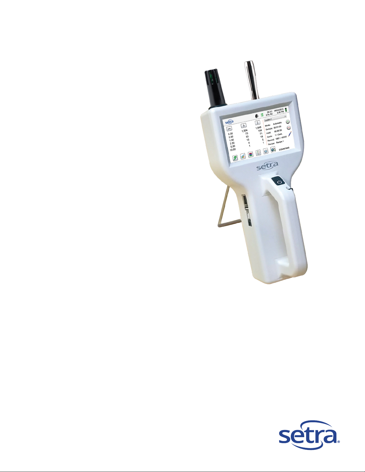
SPC8000 Series
Operating Instructions
Page 2

Copyright 2018 by Setra Systems, Inc., all rights reserved. No part of this publication may be reproduced, stored in a
retrieval system, or transmitted in any form or by any means, electronic, mechanical, photocopying, recording, or otherwise,
without the prior written permission of Setra Systems, Inc. The information contained in this docu men t const itut es proprietary
trade secrets of Setra Systems. You are not allowed to disclose or allow to be disclosed such information except as allowed
by Setra Systems in writing. No patent liability is assumed with respect to the use of the information contained herein. While
every precaution has been taken in the preparation of this manual, Setra Systems, Inc. assumes no responsibility for errors or
omissions. Neither is any liability assumed for damages resulting from the use of the information contai ned her e in.
Neither Setra Systems, Inc. nor its affiliates shall be liable to the purchaser of this product or third parties for damages, losses,
costs, or expenses incurred by purchaser or third parties as a result of: accident, misuse, or abuse of this product or
unauthorized modifications, repairs, or alterations to this product, or failure to strictly comply with Setra Systems operating and
maintenance instructions.
Setra Systems, Inc. shall not be liable against any damages or problems arising from the use of any options or any products
or accessories other than those designated as Original Setra Systems Products or Setra Systems Approved.
Products by Setra Systems, Inc. - 8000 Series
MODBUS is a registered trademark of Schneider Automation Inc.
Microsoft™, Windows™ and Excel™ are trademarks of Microsoft Corporation
NOTICE: The contents of this manual are subject to change without notice.
Product Name: Setra Systems. Inc. 8000 Series Handheld Particle Counter
Model Numbers: 8306, 8506, 8506-20, 8506-30, 8303 & 8503
The following standards are applied only to the particle counters that are so labeled. EMC is tested using Setra Systems
power supplies.
North America: EMI: FCC/ICES-003 Class A
FCC Compliance Statement for American Users
This equipment has been tested and found to comply with the limits for a Class A digital device, pursuant to Part 15 of the
FCC Rules. These limits are designed to provide reasonable protection against harmful interference when the equipment is
operated in a commercial environment. This equipment generates, uses, and can radiate radio frequency energy and, if not
installed and used in accordance with the instruction manual, may cause harmful interference to radio communications.
Operation of this equipment in a residential area is likely to cause harmful interference, in which case the user will be required
to correct the interference at their own expense.
2
Page 3

Table of Contents
Contents
1-1 Important Safety Information .................................................................................................................. 6
1-2 Ergonomic Recommendations ................................................................................................................ 7
1-3 Warnings for Use of Wireless Devices ................................................................................................... 7
1-4 Overview ................................................................................................................................................. 8
1-5 Specifications .......................................................................................................................................... 8
1-5 Specifications .......................................................................................................................................... 9
1-6 Included Accessories ............................................................................................................................ 11
1-7 Optional Accessories ............................................................................................................................ 12
1-8 Product Views ....................................................................................................................................... 14
2-1 Unpacking and inspecting the Instrument............................................................................................. 15
2-2 Registering Your Product ...................................................................................................................... 15
2-3 Contacting Setra Systems .................................................................................................................... 15
2-4 Storing and Shipping the Instrument .................................................................................................... 15
2-5 Power Considerations and Connecting to AC Mains Power ................................................................ 15
2-6 Power Considerations & Connecting to AC Mains Power .................................................................... 16
2-7 Installing Batteries ................................................................................................................................. 16
2-7 Installing Batteries (continued) ............................................................................................................. 17
2-8 Turning the Unit On ............................................................................................................................... 18
2-9 Power and Charging Status LED (on power button) ............................................................................ 19
3–1 Control and Menu Icons ..................................................................................................................... 19
4-1 Operational Flow Chart – Menu Map .................................................................................................... 23
5-1 Operation – Initial Power Up – First Time Use ..................................................................................... 24
5-2 Display .................................................................................................................................................. 24
5-3 Taking a Sample ................................................................................................................................... 25
5-4 Real-Time Meter, & Environmental PM2.5 Display Function ............................................................... 25
5-5 Recorded Data ...................................................................................................................................... 27
5-6 Reports.................................................................................................................................................. 28
6-1 Settings ................................................................................................................................................. 31
6-2 Sampling Setup ..................................................................................................................................... 31
6-3 Channel Management........................................................................................................................... 33
6-4 Locations & Recipes ............................................................................................................................. 35
6-5 Configuration ......................................................................................................................................... 39
6-6 Printer Setup ......................................................................................................................................... 40
6-7 Communication ..................................................................................................................................... 41
4
Page 4

6-8 Environment .......................................................................................................................................... 43
6-9 Passwords ............................................................................................................................................ 43
6-10 Clear All Samples ............................................................................................................................... 45
7-1 Power Management .............................................................................................................................. 45
8-1 Volume Controls ................................................................................................................................... 47
9-1 Instrument Management Software (IMS) .............................................................................................. 48
10-1 Particle Counter Host Mode – Remote Monitor and Operation .......................................................... 49
Appendix – A ................................................................................................................................................. 50
11-1 Returns ............................................................................................................................................... 51
12-1 Warranty and limitation of liability ....................................................................................................... 51
5
Page 5
1-1 Important Safety Information
This section presents important information intended to ensure safe and effective use of this product.
Please read this section carefully and store it in an accessible location.
• Do not use near explosive, flammable, or reactive gases.
• Do not attach directly to pressurized gases or liquids.
• Do not improperly discard electronic instruments, only dispose of in accordance with local
regulatory requirements or contact Setra Systems for trade-in option.
• Defective or non-working Lithium-Ion batteries must be recycled, do not throw in trash.
• This device contains a Class I laser product that is not accessible during normal operation, do not
take this device apart, exposure to harmful laser radiation can occur.
• Taking the device apart will void all warranties
• Do no use this device for any unintended purpose other than measuring of particles in ambient
environments.
• Do not operate the instrument with the inlet capped or plugged as this can cause damage to the
vacuum pump.
• Do not allow water or any other liquid to enter the inlet of the particle counter, this will damage the
unit.
• Any changes or modifications to Setra S ystems equipment not expressly approved by Setra
Systems could void the user’s authorization to operate the equipment, can risk serious injury, and
will void all warranties.
Key to Symbols
The symbols in this manual are identified by their level of importance, as defined below.
Read the following carefully before handling the product.
WARNING:
Warnings must be observed carefully to avoid serious bodily injury.
CAUTION:
Cautions must be observed to avoid minor injury to yourself or damage to your
equipment.
Important Note: The laser in this product is completely enclosed within a sensor with no user
serviceable parts. In addition, the emission level does not exceed the AEL (accessible emission limit) of
Class 1 under all conditions of operation, maintenance, service and failure.
6
Page 6
1-2 Ergonomic Recommendations
CAUTION: In order to prevent or reduce the potential risks of ergonomic injury, follow
the recommendations below. Consult with your local Health & Safety Manager to ensure
that you are adhering to your company’s safety programs to prevent employee injury.
• Reduce or eliminate repetitive motion
• Maintain a natural position while holding the Instrument
• Reduce or eliminate excessive force
• Keep objects that are used frequently within easy reach
• Perform tasks at correct heights
• Utilize a tripod or the built-in stand to use device in a freestanding mode
• Improve work procedures
1-3 Warnings for Use of Wireless Devices
Please observe all warning notices with regard to the usage of Setra Systems’ particle
counters with optional Wi-Fi communications module installed.
Safety in Hospitals
Wireless devices transmit radio frequency energy and may affect medical electrical
equipment. Wireless devices should be switched off wherever you are requested to do so
in hospitals, clinics, or health care facilities. These requests are designed to prevent
possible interference with sensitive medical equipment.
Pacemakers
Pacemaker manufacturers recommend that a minimum of 15cm (6 inches) be maintained
between a handheld wireless device and a pacemaker to avoid potential interference with
the pacemaker. These recommendations are consistent with independent research and
recommendations by Wireless Technology Research.
Persons with Pacemakers:
• Should ALWAYS keep the device more than 6 inches (15cm) from the pacemaker if
turned ON.
• Should not carry the device on your chest.
• Should use the arm furthest from the pacemaker to minimize the potential for
interference
• If you have any reason to suspect that interference is taking place, turn OFF your
device.
Other Medical Devices
Please consult your physician or the manufacturer of the medical device to determine if
the operation of your wireless product may interfere with the medical device.
7
Page 7

1-4 Overview
Thank you for purchasing a Setra Systems particle counter, the most advanced handheld instrument
available for measuring and monitoring particle counts in clean room and controlled environments for
the Aerospace, Life Science, Data Storage, IAQ and Industrial Hygiene Markets.
This user manual will provide the detailed explanation and instructions for the proper use and operation
of this feature-rich particle counter.
The Setra Systems 8000 series handheld particle counters provide the largest dynamic range of particle
size measurement from 0.3 µm to 25.0 µm of any handheld, providing for true variable binning and
allowing for channel size adjustment settings to 0.01 µm. This instrument utilizes 7 or more processors
to maintain and manage the various functions of operation. It allows for the fastest, most efficient
particle counting with high accur acy and resolution. The advanced processing also allows for many
operations to take place simultaneously, even while the unit is sampling. This includes adding
annotations to the current sample in progress, or adding annotations to previously recorded data while
sampling is in progress.
The Real-Time Meter™ function is unique in its ability to fine tune the instrument's sensitivity in order to
locate particle contamination sources with visual and audible indications. This versatile particle counter's
ability to count higher than typical particle concentrations allows the Real-Time Meter to find point
source contamination in cleanrooms as well as locating higher particle concentrations being generated
in many industrial environments.
The 8000 series handheld particle counters also have a mass concentration mode, providing for particle
mass monitoring of an environment for industrial health and safety regulatory purposes. The unit can
measure with all (6) adjustable particle size channels (3 for model 8303) or capture PM levels indicated
in µg/m3 with values corrected for particle density and refractive index correction.
The Technology designed into these particle counters includes advanced power management functions.
Onboard processors in the battery packs manage cell loading and battery life. Ad vanc ed po wer
monitoring features allow for >10 hours continuous monitoring use, or the industry’s first sleep mode that
permits the instrument to take intermittent samples over the course of a few months on one battery
charge (dependent on sample settings).
The 8000 Series handheld particle counters also boast the most versatile communication methods and
protocols of any particle counter on the market. The instruments allow for Ethernet or Wi-Fi, and USB
Host or USB Client connectivity, providing for MODBUS RTU, ASCII, TCP, web-hosted server for
remote operation, and USB connection to a PC or to a thumb drive for data uploads or downloads. The
remote web server hosting feature allows for monitoring and control of the particle counter from any PC,
smartphone or tablet simply by inputting the IP address of the particle counter on the local area network
and entering it into any browser. The main processors allow for multiple connections from operators,
staff and management, all with simultaneous access to review, monitor and control the operation of the
instrument.
Thank you,
1-5 Specifications
8
Page 8

1-5 Specifications
Model 8306
Model 8506
Model 8506-20
Model 8506-30
Size Range
0.3 to 25 μm (8506-20: 0.5 to 55 μm, 8506-30: 0.5 to 75 μm)
Size Channels: Model 8303
Factory calibrated at 0.3, 0.5, 5.0 μm variable binn ing
Size Range
0.3 to 25μm
Size Channels: Model 8503
Factory calibrated at 0.5, 1.0, 5.0 μm variable binning
Size Range
0.5 to 25μm
Flow rates
0.1 CFM (2.83 LPM)
Zero Count
<1 count / 5 minutes (<2 particles / ft³) (per ISO 21501-4 & JIS)
Automatic, manual, cumulative/differential, mass concentration, count or
concentration
Count Alarms
1 to 9,999,999 counts
Display
4.3″ (10.9 cm) WQVGA (480×272) color touch screen
Printer (Optional)
External thermal printer
Vacuum Source
Internal pump with automatic flow control
Filtered Exhaust
Internal HEPA filter
Number of Channels
6
Custom Size Channels
Calibration for custom size channels available
Audible Alarm
Adjustable built-in alarm
Removable Li-ion
>10 hours continuous operation and >16 hours normal operation
Battery Recharge Time
<2 hours
Reports
ISO 14644-1, EU GMP Annex 1, FS 209E
Recipes
50 user-configurable recipes
Alarms on counts for all particle sizes, low battery, sensor failure,
environmental sensors and flow
10” x 5” x 4.5” (25.4 cm x 12.9 cm x 11.4 cm) includes handle and does not
include probes
Size Channels:
Size Channels:
Channels:
Channels:
Light Source Long life laser diode
Counting Efficiency 50% @ 0.3 μm; 100% for particles >0.45 μm per JIS
Count Modes
Calibration NIST traceable
Factory calibrated at 0.3, 0.5, 1.0, 2.5, 5.0, 10.0 μm variable binning
Factory calibrated at 0.5, 0.7, 1.0, 3.0, 5.0, 10.0 μm variable binning
Factory calibrated at 0.5, 0.7, 1.0, 5.0, 10.0, 20.0 μm variable bi nni ng
Factory calibrated at 0.5, 0.7, 5.0, 10.0, 20.0, 30.0 μm variable binning
Battery
Communication Modes Ethernet and USB
Optional Communication
Modes
Environmental Sensor
Alarm
Standards ISO 21501-4 and JIS B9921
Calibration Recommended minimum once per year
External Surface High impact injection molded plastic
Dimensions (L x W x H)
Wireless 802.11 b/g, RS485 or RS232
Includes temperature and relative humidity probe 32º to 122ºF (0º to 50ºC)
±1ºF (0.5ºC), 15-90% ±2% relative humidity (OPTIONAL FOR 8303)
9
Page 9
1-5 Specifications (continued)
45,000 sample records (rotating buffer) including particle count data,
environmental data, locations and times. Scrollable on screen or printout
Sample Locations
Up to 1,000 locations 20 characters long
Sample Time
1 second to 99 hours
Power
110 to 240 VAC 50/60 Hz universal in-line power supply
Operating Conditions
41º to 104ºF (5º to 40ºC) / 20% to 95% non-condensing
Weight 2.2 lb. (1.0 kg)
Quick start guide, operating manual on USB flash drive, isokinetic probe,
Accessories
temperature relative humidity sensor, purge filter, battery, data download
software, USB cable, power supply & cable (8303 Rh/Temp Probe Optional)
Optional Accessories
Printed manual, carrying case, spare battery, external battery charger,
external printer and isokinetic probes
Buffer Memory
Storage Conditions 32º to 122ºF (0º to 50ºC) / Up to 98% non-condensing
Warranty 2 Years. Extended warranties available.
Please note that specifications are subject to change without notice.
10
Page 10
Description
Part Number
Image
Nickel Plated Aluminum
PS-12041
Purge Filter Assembly 0.1 CFM (2.83 LPM)
AS-99002A
Rechargeable Battery 55Wh
EE-80003A
(NOTE: This probe is optional for Model 8303)
EE-80014A
(Select adapter -US, -EU, -UK or -CN)
EE-80127-XX
USB Cable 6' (1.8m)
AS-99010
Management Software (USB Key)
MN-24001
1-6 Included Accessories
Isoprobe Threaded 0.1 CFM
Temperature / RH Probe 32-122°F (0-60°C)
±1°F (0.5°C), 15 - 90% ±2%
Power Supply 15V ~2amp 100-240VAC
Handheld User Manual and Instrument
11
Page 11
Description
Part Number
Image
Antenna
EE-80092
Handheld Carrying Case
AS-99015
External Battery Charger 55Wh
AS-99005A
Rechargeable Battery 55Wh
EE-80003A
External Thermal Printer with 2 rolls of paper
AS-99011
External Thermal Printer Paper - 1 Roll
AS-99012
10 Pack
AS-99013
External Thermal Printer Spare Battery
AS-99014
1-7 Optional Accessories
Wireless 802.11 b/g Output with Internal
External Thermal Printer Cleanroom Paper -
12
Page 12
Description
Part Number
Image
Stainless Steel
PS-12070
Stainless Steel
PS-12022
1/8" Inlet Barbed Fitting Stainless Steel
PS-12005
Sample Tubing 1/4" OD (1/8" ID) per foot
AS-99018
Handheld User Manual (Printed)
MN-24001P
Handheld Validation Manual
MN-24002
Certificate of Origin
MN-24000
1-7 Optional Accessories (Continued)
Isoprobe Threaded 0.1 CFM (2.83 LPM)
Isoprobe Barbed 0.1 CFM (2.83 LPM)
13
Page 13
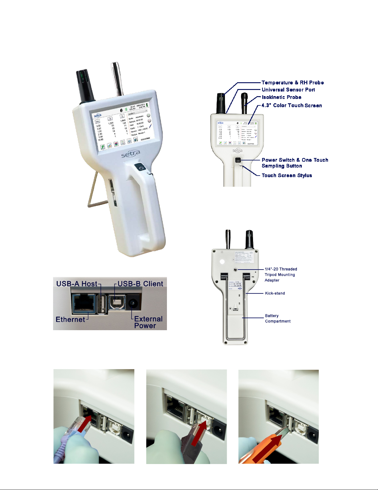
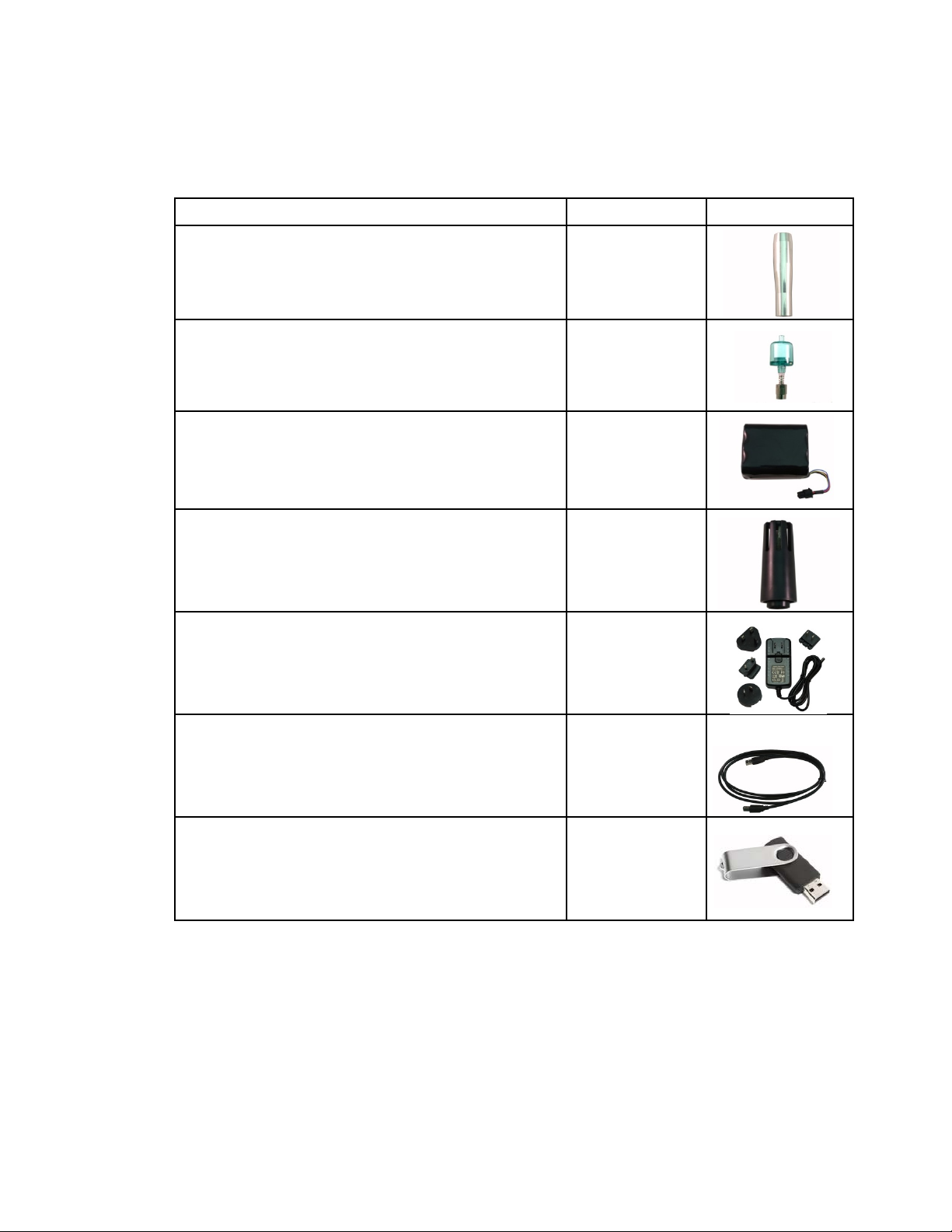
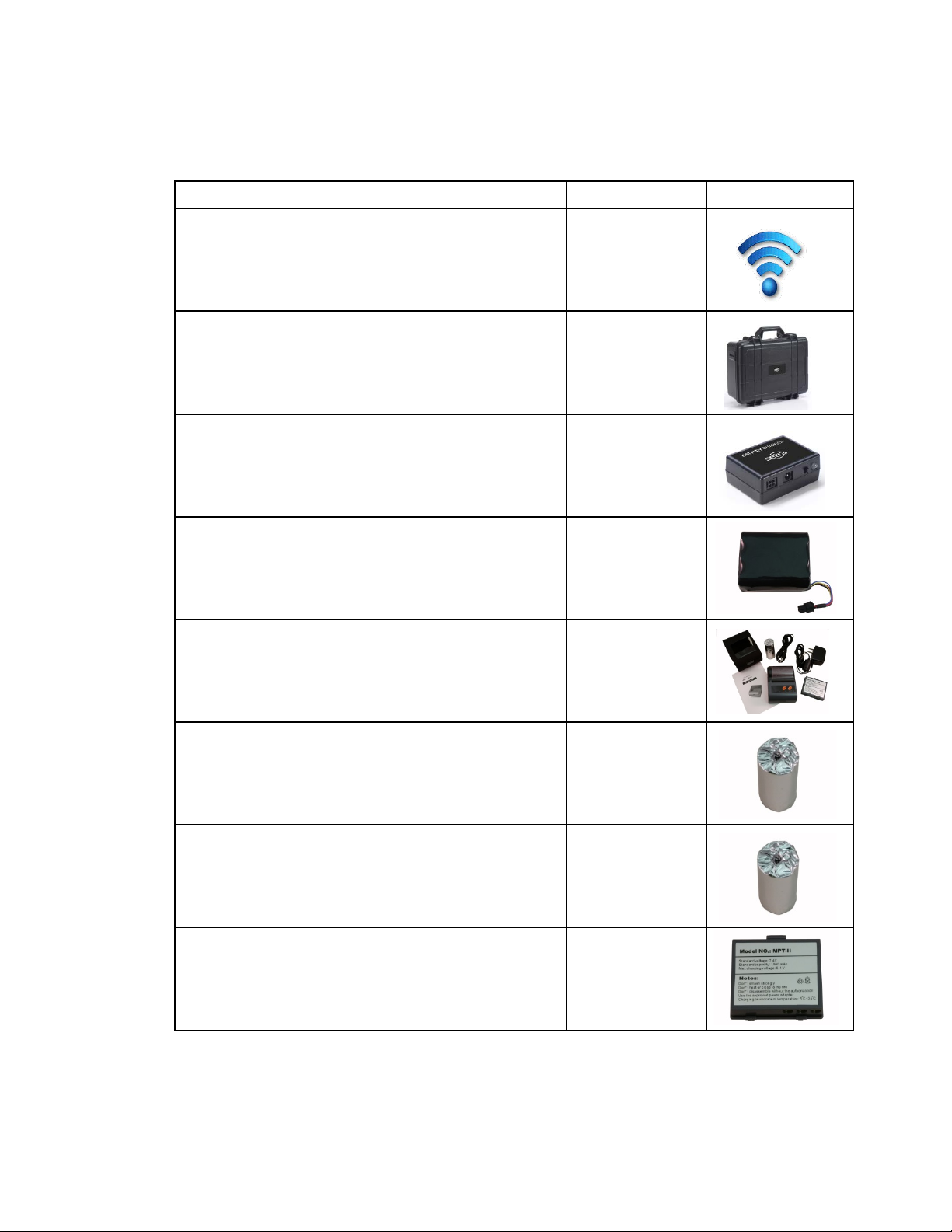
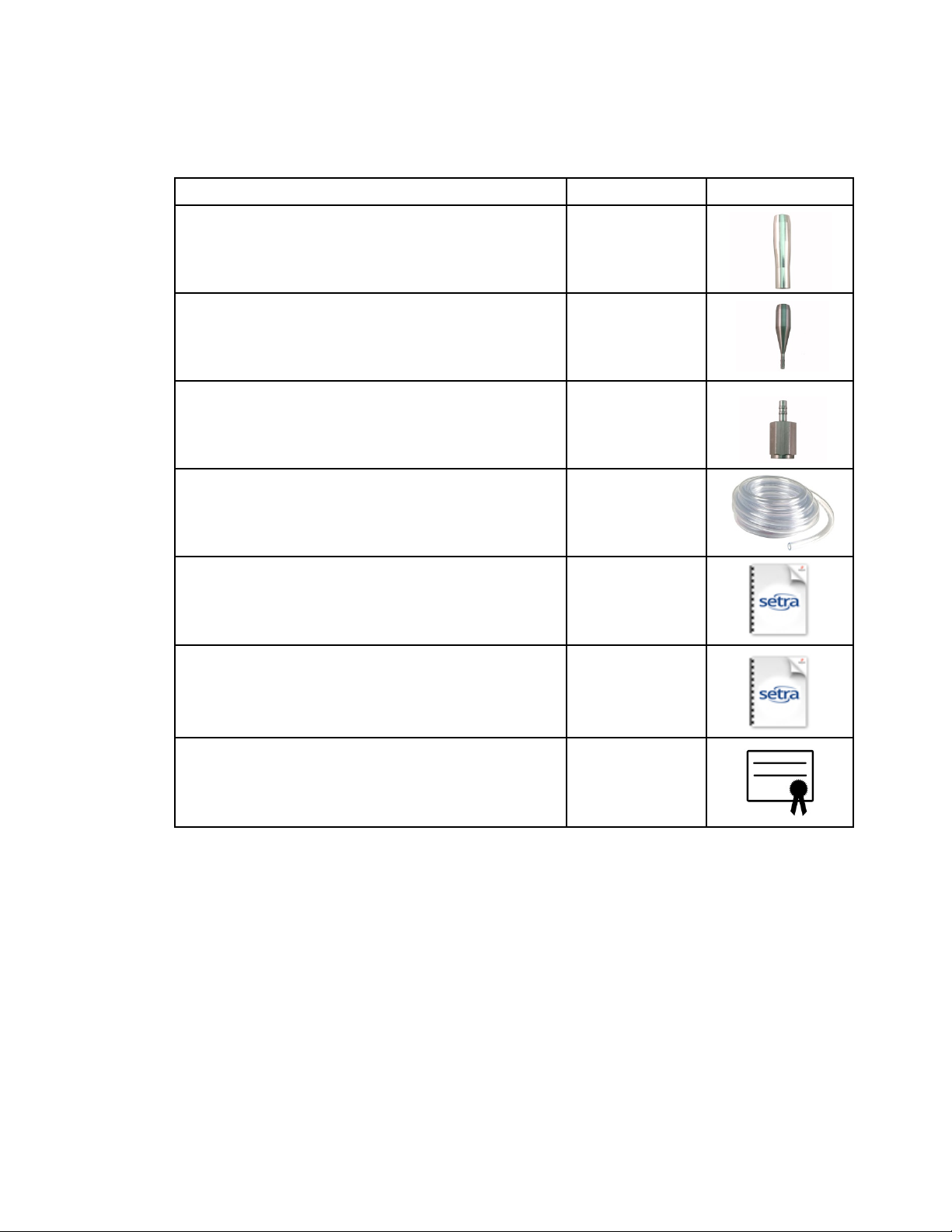
Left Side View – Input / Output Connections
Rear View
Connecting Ethernet Cable
Connecting USB - B Client
Connecting USB - A Host
Front View
1-8 Product Views
14
Page 14

Unpacking and Preparation for Use
2-1 Unpacking and inspecting the Instrument
Careful consideration was gi ven to our packing material to ensure that your Setra
Systems Instrument will reach you in perfect condition. If the Instrument has been subject
to excessive handling during shipping, there may be visible damage to the shipping
carton. In the event of damage, keep the shipping container and packing material for the
carrier’s inspection. Carefully unpack the Instrument from its shipping container and
inspect the contents for damaged or missing items. If the Unit appears damaged or
something is missing, contact the carrier and Setra Systems immediately. Please save
the container and packing material in case you have to return the Instrument.
2-2 Registering Your Product
All Setra Systems Instruments are automatically registered upon sale for the warranty
period and tracked by Serial number.
2-3 Contacting Setra Systems
To order accessories, receive technical assistance, report damaged or missing items
from your shipment, or get contact information for your nearest Setra Systems authorized
reseller, call +1-800-257-3872 or Local: +1-978-264-0292
2-4 Storing and Shipping the Instrument
This instrument utilizes a high quality advanced Lithium Ion Power Cell. This must be
removed from the device prior to shipping the unit. If the unit needs to be packed and
shipped for annual calibration or service, it is recommended to use the original packing
materials. If they are not available please insure that the instrument is packaged in a box
that is sturdy and that the unit is well protect e d with proper packing materials to cushion
and protect it from harm during transit.
To store the instrument, place it in its optional case or in a box, under cover, in an
environment as stated in our specifications
2-5 Power Considerations and Connecting to AC Mains Power
The Setra Systems Instrument comes with a power adapter line cord for AC mains
powered operation and battery charging. The power adapter is designed to operate with
line voltage from around the world. The correct plug adapter must be used to match your
local AC power adapter standard. If the Instrument power adapter does not have the
proper plug configuration, please contact Setra Systems or an authorized reseller for
service.
15
Page 15
2-6 Power Considerations & Connecting to AC Mains Power
To install the country specific plug adapter, simply slide the adapter into the power supply
as shown.
2-7 Installing Batteries
CAUTION - The Setra Systems’ rechargeable battery model EE-80003A is an intelligent
battery pack with onboard processing to ensure proper cell loading and other functions
that support the advanced power management features of this instrument. To ensure a
long life for the batteries and for adherence to any local regulatory guidelines for the use,
storage and disposal of Lithium Ion batter ies please follow these instructions carefully.
WARNING – Do not plug in, or charge the Setra Systems Lithium-Ion rechargeable
battery with any other power source other than the approved S etr a S ystem s
Rechargeable Batter y External Char ger - Model AS-99005A, or using the Setra Systems
Power Supply Model EE-80127-XX. Using any other charger can cause fire, shock or
serious injury.
Caution: Dispose of Setra Systems lithium-ion
batteries only at an approved local battery recycling
center.
16
Page 16

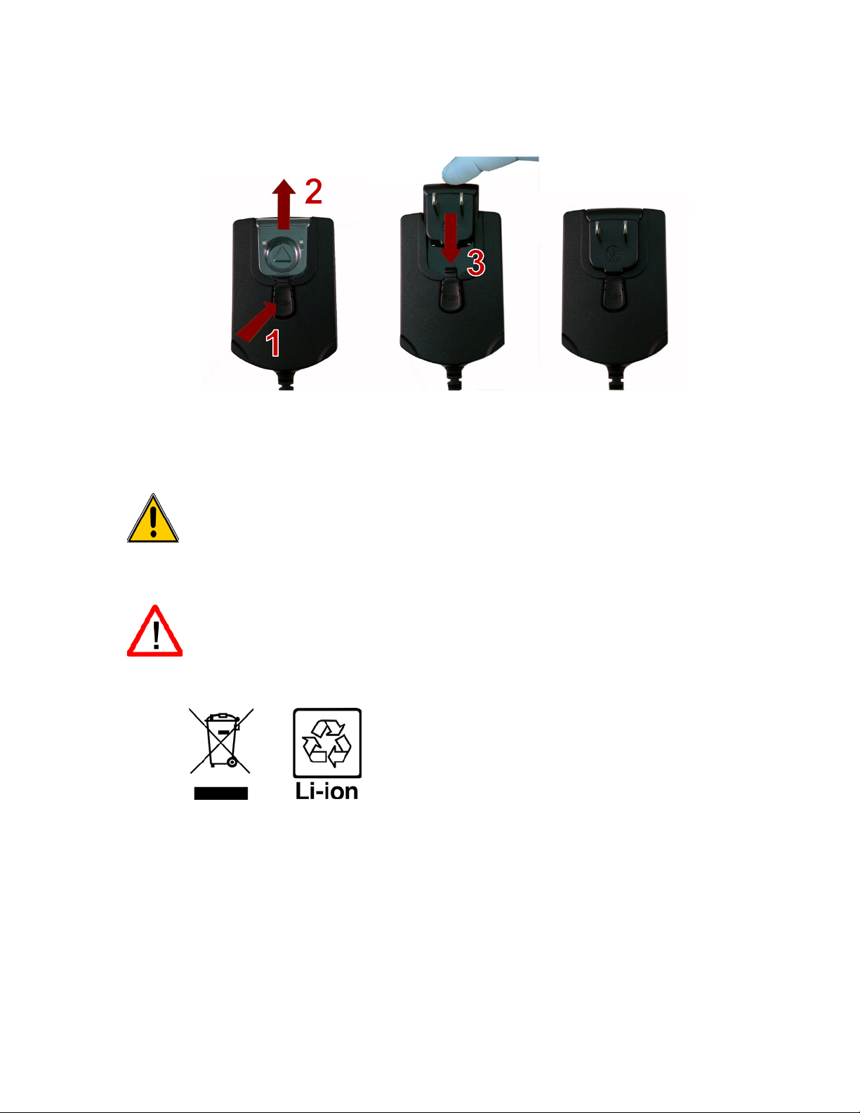
Step 1 - Remove security screw
Step 2 – Pull out kick-stand.
Step 3 – Push down latch while pulling
Step 4 –Insert battery connector plug
of connector.
2-7 Installing Batteries (continued)
Install the Setra Systems Battery pack into the instrument using the following steps:
with Phillips screwdriver.
3
battery compartment cover out and away.
into matching socket on PCB board in
battery compartment. NOTE: red and
black lead should be on bottom edge
17
Page 17

Step 5 – Carefully push bat tery into the
Step 6 – Seat the battery’s compartment cover into
2-7 Installing Batteries (continued)
compartment using an upward motion until
bottom of battery clears edge of the
compartment and drops in freely.
2-8 Turning the Unit On
The External one-touch power and sample button on the handle will power the instrument
on and off and will turn sampling on and off.
The one-touch external power button is conveniently located on the particle counter
handle to allow for easy one touch operation. Holding the handle, place thumb over the
button and press and hold until the particle counter turns on.
Pressing the button momentarily starts the
pump and begins sampling.
Pressing the one-touch button again for 1
second stops sampling.
Holding the button for 2.5 seconds turns the
instrument off.
bottom slot and push inward until the locking latch
clicks. The security screw can be reinstalled with a
screw driver or it can be removed for optional battery
replacement use.
The unit can also be turned off from the
power management screen.
18
Page 18
Function Name
Location/Screen
Description of Function
Unit plugged into AC (instrument screen on or off)
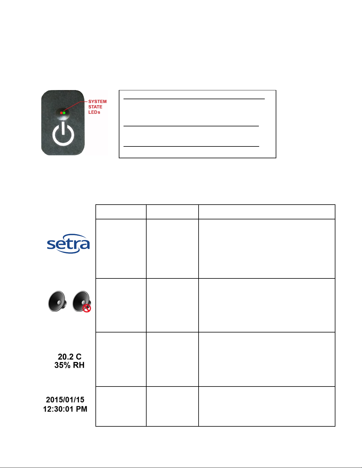
2-9 Power and Charging Status LED (on power button)
Power and charging status is indicated externally on the instrument in the middle of the
one-touch power and sample button. The indication provides information on the charging
rates and status (shown on right).
Charging: Red LED on
Charging Complete: Green LED on
Unit not plugged into AC (instrument screen on)
Battery Charge <10%: Red LED blinks every 3 seconds
Unit not plugged into AC (instrument screen off)
All LED’s off
3–1 Control and Menu Icons
Setra logo icon Home Screen
Press logo and a Product Information Scr e e n wil l
appear displaying your model number, serial
number, manufacture date, last calibration date,
next calibration due date and number of channels
activated on the unit. Press back arrow icon on
bottom left corner of the display to return to home
screen.
Speaker icon
Temperature &
RH indication
Time and Date
Indication
Home Screen
Home Screen
Home Screen
Speaker Icon allows for volume adjustment using
a pop-up slider bar. When pressed the cross bar
on slider and move up and down for volume
control. Icon will have red prohibited s ymbol
when sound is turned off or muted.
By pressing the temperature and RH value
indication the screen will change to a large
indication of the current Temperature, Relative
Humidity and the current Barometric Pressure.
Press back arrow icon on bottom left corner of
the display to return to home screen.
To change time and date, press the date and
time in the top right corner of the display and the
change time and date screen will appear allowing
for changes
19
Page 19

Function Name
Location/Screen
Description of Function
USB drive.
3–1 Control and Menu Icons (Continued)
Power
Management
Icon
Home Screen
On the top right of the display is the
battery/power adapter indication icon. Pressing
this icon displays the battery power
management screen as well as the current
battery status.
USB
Communication
Icon
Printer
Indication
System
Warning
Indication
Alarm
Indication
Run Icon Home Screen
Home Screen
Home Screen
Home Screen
Home Screen
If a USB drive is connected, the USB Icon will
appear. When pressed from the home screen
the current record displayed will be saved to the
If the Setra Systems Printer is connected to
USB Port, the Printer Icon will appear. When
pressed from the home screen the current
record on screen will be sent to the printer.
When the System Warning Indication Icon
appears, please contact Setra Systems
technical service for assistance. When pressed,
the Instrument will display additional
information.
Visual indication of alarm condition if the particle
count exceeds the user defined thresholds.
When pressed this will silence the alarm.
The Run Icon starts the instrument sampling.
Once pressed the Run Icon will be replaced by
the Stop Icon.
Stop Icon Home Screen
Real-Time
Meter &
Environmental
TPM Screen
Icon
Recorded Data
Icon
Home Screen
Home Screen
The Stop Icon stops the instrument from
sampling.
Pressing the Real-Time Icon switches between
the Real-Time Meter mode, graphing of
pulse/seconds, The environmental PM2.5
indication display (with mass mode enabled)
and the Main Screen.
When pressed, the Recorded Data Icon will
display the saved data records page. All saved
records can be accessed from this screen.
20
Page 20

Function Name
Location/Screen
Description of Function
When pressed, the Particle Data Icon changes
cumulative counts.
3–1 Control and Menu Icons (Continued)
Reports Icon Home Screen
Particle Data
Selection Icon
Home Screen
When pressed, the Reports Icon will display the
standards options page, where ISO 14644-1,
EU-GMP Annex 1, or Federal Standard 209E
modes can be selected.
the indicated values from particle count, count
per cubic meter, or count per cubic foot and
particle mass concentration (activated in
channel management). These values are
displayed simultaneously as differential and
Differential
Mode Icon
Cumulative
Mode Icon
Location Menu
Icon
Mode
Indication
Sample
Indication
Home Screen
Home Screen
Home Screen
Home Screen
Home Screen
When pressed, the Differential Mode Icon
toggles the differential data values off and on the
display during or after sampling.
When pressed, the Cumulative Mode Icon
toggles the cumulative data values off and on
the display during or after sampling.
When pressed, the Location Menu Icon displays
the Location and Recipe set up pages. This
feature allows for the input of up to 1000
locations 20 characters long and up to 50 unique
user-defined recipes.
The Mode Indication displays the current mode
of operation the instrument is set to. These
modes include automatic, manual, and
continuous.
The Sample Time Indication displays the current
sample time duration (Hours:Minutes:Seconds).
This value will countdown from the set value for
the sample time, displaying the amount of time
left in the current sample. See Sampling Setup
in Settings Menu.
Hold Indication Home Screen
Cycle
Indication
Home Screen
The Hold Time Indication displays the current
hold time, as an interval between samples. The
maximum hold time is 99 hours, 59 minutes and
59 seconds. See Sampling Setup in Settings
Menu.
The Cycle Indication displays the number of
count samples that will be taken at a location in
automatic mode. The maximum number of
possible cycles that can be set is 9,999. The
value is displayed as the sample number vs. the
total number of samples to be completed in this
cycle. See Sampling Setup in Settings Menu.
21
Page 21

Function Name
Location/Screen
Description of Function
The Annotation Icon, displays as a blue pencil.
Settings.
The three horizontal arrows indicate that the
pump is working and that the internal flow
Record: 1 / 45000
3–1 Control and Menu Icons (Continued)
Record
Indication
Settings Menu
Icon
Annotation
Icon
Home Screen
Home Screen
Home Screen
The Records Indication is a display of the total
number of sampling records saved in the
Instrument out of the total number of records the
instrument is capable of storing -- 45,000
possible saved records (rotating buffer) including
particle count data, environmental data,
locations and times per record.
When pressed, the Settings Menu Icon brings
you to the Settings Screen. All aspects of the
Instrument’s set-up can be managed from the
icon driven sub-menus.
When pressed, written notation (up to 32 letters,
can be added to a record during the time of the
sampling, or after a sample has been taken.
Advanced processing allows for annotations to
be inserted while the unit is sampling with no
interruption to the operation. The
over a document denotes that an annotation
exists on that record. This feature can be
disabled from the Configuration screen in
green pencil
Plus and Minus
Button
Green Flow &
No Flow
Indication
Back Arrow
Icon
Home Screen
Home Screen
Various Screens
throughout
program
When pressed, these icons scroll through 1000
possible locations that can be saved and
uniquely identified in the Locations set-up
screen. Locations can have set recipes
assigned to them in advance for ease-of-use
during sampling.
sensor is detecting the correct flo w rate through
the Instrument. If a red lin e appears di agonally
through three green arr ows , it is an indicat ion no
flow.
Press back arrow Icon to return to the previous
screen.
22
Page 22

Audio Volume
Communications
Channel Alarm
A
A
4-1 Operational Flow Chart – Menu Map
Print
Information
Shut Down
Information Environment
Print Current
Record
Set
Zoom
Real-Time
Meter
Main
Charts
Recorded
Data
Print
Records
Reports Settings
Sampling
Setup
Channel
Management
Locations &
Recipes
Date / Time
Set
Configuration
Power
Management
Location &
Recipes
Location
Advance
Annotate
Record
Printer
Setup
Setup
Environment
Setup
Password
Setup
Clear
Samples
Modbus
Setup
Setup
Configuration
Load/Save
Factory
Restore
ISO 14644-1
EU-GMP
Annex 1
FS 209E
Room
Definition
Report
Generate
Room
Definition
Report
Generate
Room
Definition
Report
Generate
Print
Report
Admin Password Not Required
Admin Password Required to Edit
23
Admin Password Required to View
Page 23

5-1 Operation – Initial Power Up – First Time Use
Date Format Select
Choose format for - Month/Day/Year, Day/Month/Year, or
Numeric Keypad
Touch date window, a numeric keypad will appear to allow for date
Time Format Select
Choose 12 hour or 24 hour clock indication by select in g the
Numeric Keypad
Touch time window, a numeric keypad will appear to allow for time
Back Arrow Icon
Press back arrow Icon to return to the previous screen.
Un-Zoomed View
Zoomed View
After the Particle Counter turns on for the first time a window will appear stating “Time of Day
Clock Not Set”. Press OK to Set Clock.
Button
Button
5-2 Display
The large color touch screen can zoom in and out on the home page at any time simply by
touching any blank space on the screen.
Year/Month/Day indication by selecting the corresponding button on the
touchscreen.
change. For change or correction of input values navigate using < or >
to move cursor. When complete press OK button
corresponding button on the touchscreen.
change. Use 24 hour clock format for time entry to properly indicate AM
or PM. For change or correction of input values navigate using <or> to
move cursor. When complete press OK button- Time will display with
AM/PM or in 24 hour format based on format selection.
24
Page 24

5-3 Taking a Sample
Taking a
Using the one touch
To take a sample, select the start sample icon on the
Stopping
Using One Touch
To stop the sampling event press the stop icon on the
Data Unit of Measure
The instrument can display the active sample or any
indication options.
Note:
Main Sampling Home Screen
Model 8303
only displays
(3) channels
Sample
the
Sample
Important Note: Use minimum of 3 second sample to avoid unwanted counts. If a default
of 3 seconds is not used, stray particles could be counted at start of sample.
power/sample button
on the handle or the
start sample Icon on
the display begins
the sample.
Handle button or the
Stop Sample Icon on
the display
Selection
display, or momentarily press the one touch button on
the particle counter's handle. This will begin the sample
according to the sampling set up parameters displayed
on the right side of the home display. The sample
setting can be changed in the settings sub-menus.
display or momentarily press the one touch button on
the particle counter's handle.
recorded and saved record in count, counter per cubic
meter, count per cubic foot, or micrograms per cubic
meter (in mass mode, if enabled from the Channel
Management Screen). This can be changed on the fly
by pressing the icon, rotating through the data output
5-4 Real-Time Meter, & Environmental PM2.5 Display Function
The Instrument will display a bar graph visualization that rises and falls with the
increase of pulses counted per second, per channel. This allows for the pinpointing of
the cause of the contamination that is being detected in the environment. The closer
the instrument is to the source, the higher the indication appears on the bar graph.
This feature also graphically displays the pulses per second if the graph function is
chosen, making the graph’s historical information useful in point source detection.
25
Page 25

5-4 Real-Time Meter and Graphing Function (continued)
Start/Stop Sampling
The Sampling can be started or stopped from this screen
Channel Select –
Select the channel size that is the focus of the
Range – Sensitivity
Using the touchscreen, drag the green Range slider bar up
Switch to Particles Per
Pressing the Real-Time Meter Icon again, switches to the
display to the home screen.
Range
Channel 3 selected & signal at maximum value
Range Slider Lowered to reduce Channel 3 value
Real-Time Meter Particles/Second Graph
PM 2.5 Environmental Conditions Display
Press the value to select and
change the PM size displayed
While on Real Time Meter Page, the following steps allow for the features operation.
while on Real-Time
Meter or Pulse Per
Second Screen
Radio Button
Adjustment Slider
Second Screen, or to
Environmental PM2.5
Display
using the Start/Stop icon buttons , or by using the one touch
button on the handle.
contamination being in vesti gate d by clicking on the radio
select button on the bottom of each channel. The channel
selected also represents the data being displayed in the
pulses per second graph mode.
towards the top of the slider. This allows for the greatest
sensitivity and signal from the contamination within the test
area. As the unit gets closer to the concentration source the
visual signal can increase and hit 100% of the indicated
scale long before the actual source of the contamination is
found. By pulling the Range Slider down, the sensitivity is
reduced and the indication scaled down. This allows for
more precise detection when getting closer to the
contamination source. This procedure can be repeated until
the source is identified.
Particles per second graphical display page. Pressing it
one more time displays the Environmental PM2.5 Air Quality
Display. Pressing the Icon one more time returns the
26
Page 26

5-5 Recorded Data
Print or Save the
If a Printer or USB thumb drive is attached to the instrument,
Turn off Indicated
All displayed channel values can be turned off or back on from
Change Indicated
The Recorded data indication can be changed to the
Adding Annotation
The Particle counter will save up to 45,000 records. These records can be accessed by
selecting the recorded data icon. The Recorded data page uses a horizontal slider bar
that allows scrolling left and right through all records. Click on the white arrows for fine
control in locating a specific record. Press the slider button with the stylus and drag left
or right to navigate through large amounts of records quickly.
IMPORTANT NOTE: After the 45,000th sample is recorded the software must delete
one block of flash memory to make room for the next record. Each block contains 28
records. After 28 records are deleted the next record number will become 44,972. The
instrument will then count back up to 45,000 again. Each block removed is from the
oldest records (first in, first out method).
Recorded
Data Screen
Current Record
being displayed
Cumulative or
Differential value
Columns
Data Units
To Recorded Data
To add an annotation to an existing record, click
on the Blue Pencil Annotation Icon. This allows for
the inclusion of a written notation for the current
sample record selected. The Annotation Keyboard
will be displayed and the note can be entered. The Green pencil denotes that an annotation exists on
that record. This feature can be disabled from the Configuration screen in Settings.
the current record on the Recorded Data Screen can be
downloaded or printed by pressing the corresponding Printer
or USB Icon.
the recorded sample record by toggling the mode icons.
corresponding calculated values by pressing the Particle Data
Selection Icon. Press the icon to change view between particle
count, count per cubic meter, count per cubic foot, or
micrograms per cubic meter (if enabled for mass concentration
mode in Channel Management).
27
Page 27

5-5 Recorded Data (continued)
Saved Annotation
The green pencil over a document denotes that an an notat io n
Special Notes –
Holding down the Shift button will activate or de-activate the
ISO 14644-1
Selecting this report icon allows for the generation of a report
EU-GMP Annex-1
Selecting this report icon allows for the generation of a report
FS 209E
Selecting this report icon allows for the generation of a report
Accessing ISO,
Annotation Keyboard
5-6 Reports
Indication and Icon
Cap Locks and
Delete
Statistics
GMP, or Federal
Standard Report
Functions
exists on that record. The annotation can be accessed or
edited at a later time.
cap locks functions. Holding down the backspace key will
delete all text entered on the text line.
Pressing the Statistics icon will prov ide an ons cr een di splay of
the min, max, and average values for the records selected.
This function is disabled if a printer or USB stick is connected
to the instrument.
based on the parameters and guidelines of the ISO standard.
based on the parameters and guidelines of the European
GMP Annex-1 standard.
based on the parameters and guidelines of the US Federal
Standard 209E.
28
Page 28
5-6 Reports (continued)
Create Report
Generate
Selecting the specific report icon from the Reports Screen displays information for the chosen standard.
The room parameters can be defined by pressing the Room Definition Button. To generate a report,
select the Generate Report button. This creates a report document that can be saved to an external
thumb drive, or printed to a connected printer.
By holding down the Create Report Button for 5 seconds, a sample report will be displayed with the
current test records. These records will be added to the system’s recorded data so that the va lues and
information can be reviewed prior to actually completing the report and saving to an external source.
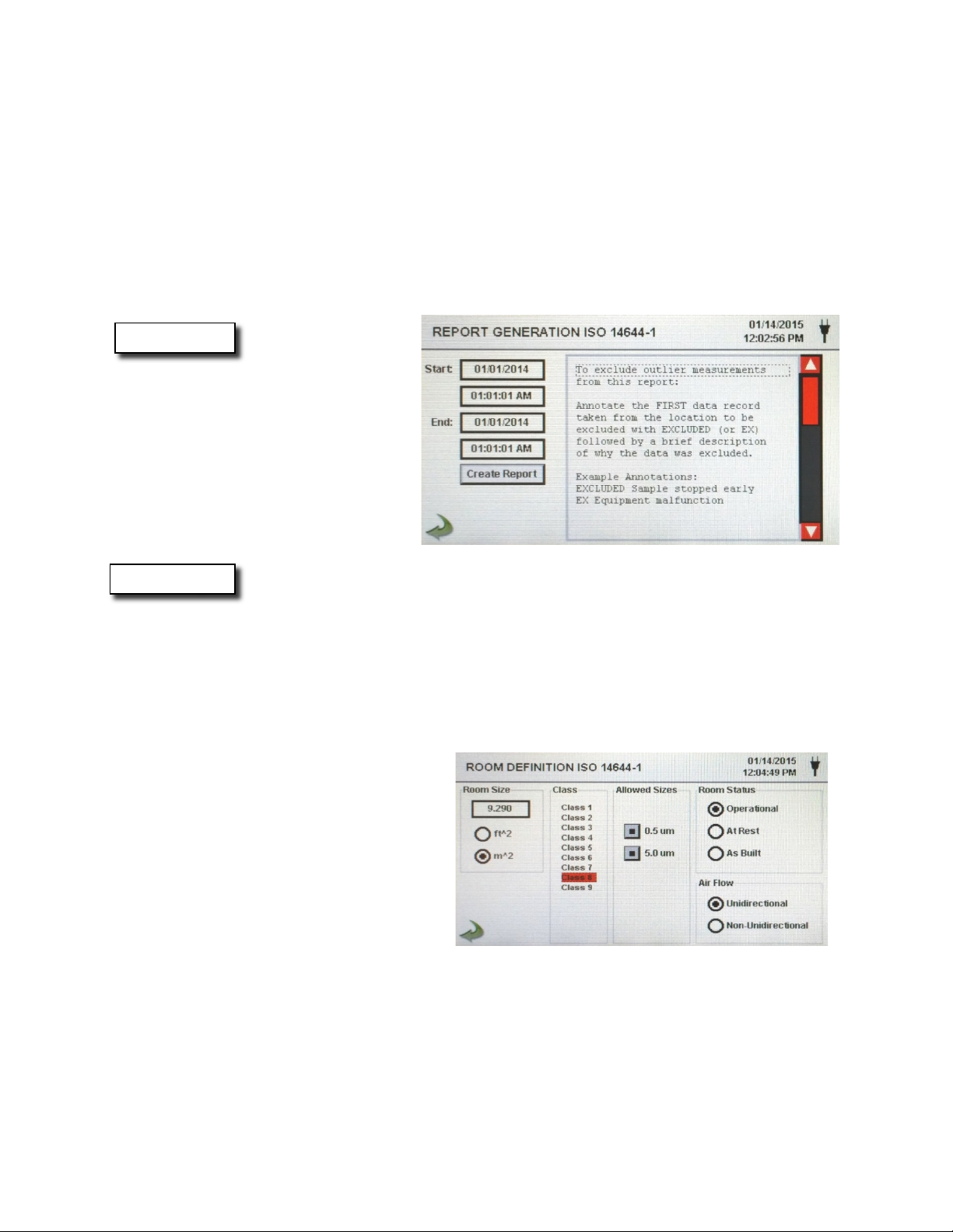
Create Report
After selecting Generate,
the Report Generation
screen displays.
The Start/End time and date are selected to enter the values. The report is created
using the Create Report Button. If the values of the count or sampling set-up are
incorrect, the report will indicate the errors prior to the report being generated. To
exclude outlier measurements from the report:
Annotate the FIRST data record taken from the location to be excluded with
EXCLUDED (or EX) followed by a brief description of why the data was excluded.
Example Annotations: EXCLUDED Sample stopped early or EX Equ ipment failure.
Room Definition
Each report standard has a Room Definition page that allows for information to be
input defining the output of the generated report. Room size is input in square feet
or square meters. The ISO class of the cleanroom being tested is selected, and the
allowable sizes may be included or excluded in the report. The Room Status is
selected as being Operation, At Rest, or As Built per the standard specification
requirements. Airflow is recorded as being Unidirectional or Non-Unidirectional.
29
Page 29
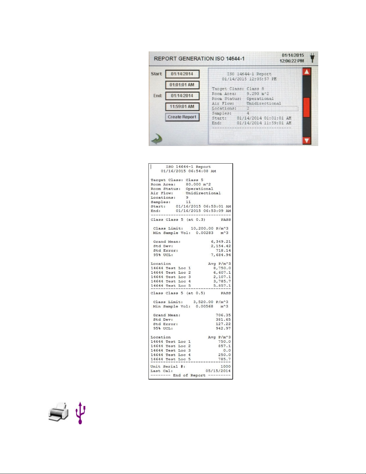
Printing or
To Print a report on screen, or save it to an installed thumb
5-6 Reports (continued)
Sample of
Report Output
Printed Report
Sample
Saving a Report
drive, press the corresponding icon on the.
Note: a thumb drive or printer must be connected to the
instrument to display these icons.
30
Page 30

6-1 Settings
Delay
Pressing the Delay time box opens the Enter Time screen. The
Settings Screen Select the Settings Icon to enter the main configuration menu.
6-2 Sampling Setup
All settings for the instrument are accessed through this
Settings screen. When the administrator password is in use,
this screen is not available to regular users and may only be
accessed and settings modified by the administrator.
Settings Screen The Sampling Setup Icon displays the Sample Timing, and
Sample Volume Units selection windows. The option to utilize
recipes instead of the general Sample Timing setup values is
also accessed on this page with a selection box.
numeric touchpad is used to enter the amount of time the counter
will wait before starting a sample in automatic mode.
The entry is made in Hours:Minutes:Seconds (HH:MM:SS). The
maximum delay time is 99 hours, 59 minutes and 59 seconds.
This feature is ideal to allow the operator to leave the area before
the sampling begins.
31
Page 31

5-6 Sampling Setup (continued)
Sample
Pressing the Sample Button opens the Enter Time screen with
Volume
Pressing Volume displays the numeric touchpad for the entry of
Hold
Pressing the Hold Button opens the Enter Time screen with
Cycles
Pressing Cycles displays the Enter Cycles Screen with numeric
Mode
The Mode icon opens the Select Sample Mode page. Select
Sample Volume
Choose from three different sample volume units:
Use Recipes
The Use Recipes button activates the Recipe Setup Page.
Back Arrow
Press back to last screen arrow on bottom left corner of the
Units selection
numeric touchpad for the entry of the amount of time the counter
will sample in automatic mode. The entry is made in
Hours:Minutes:Seconds (HH:MM:SS). The maximum sample
time is 99 hours, 59 minutes and 59 seconds.
the desired volume to be sampled. The volume will correspond to
the units selected in the Sample Volume Units Selection on the
Sample Setup Screen. The volume value entered will c ontrol the
length of time per sample to achieve the desired sample volum e.
numeric touchpad for the entry of the amount of time the counter
will hold between samples in automatic mode. The entry is made
in Hours:Minutes:Seconds (HH:MM:SS). The maximum Hold
delay time is 99 hours, 59 minutes and 59 seconds.
touchpad for entry of the number of sampling cycles to be taken
at a specific location when the unit is in automatic mode.
Enter ZERO (0000) to activate Continuous Sampling Mode.
Automatic mode or Manual Mode. After making a selection, press
OK to accept and return to the previous page, or select cancel.
Cubic Feet (ft^3), Cubic Meters (m^3) or Liters.
Button
Icon
Recipes associated with locat ions wil l be utili zed in place of the
general settings from the Sample Timing Setup screen.
display to return to main settings screen.
32
Page 32

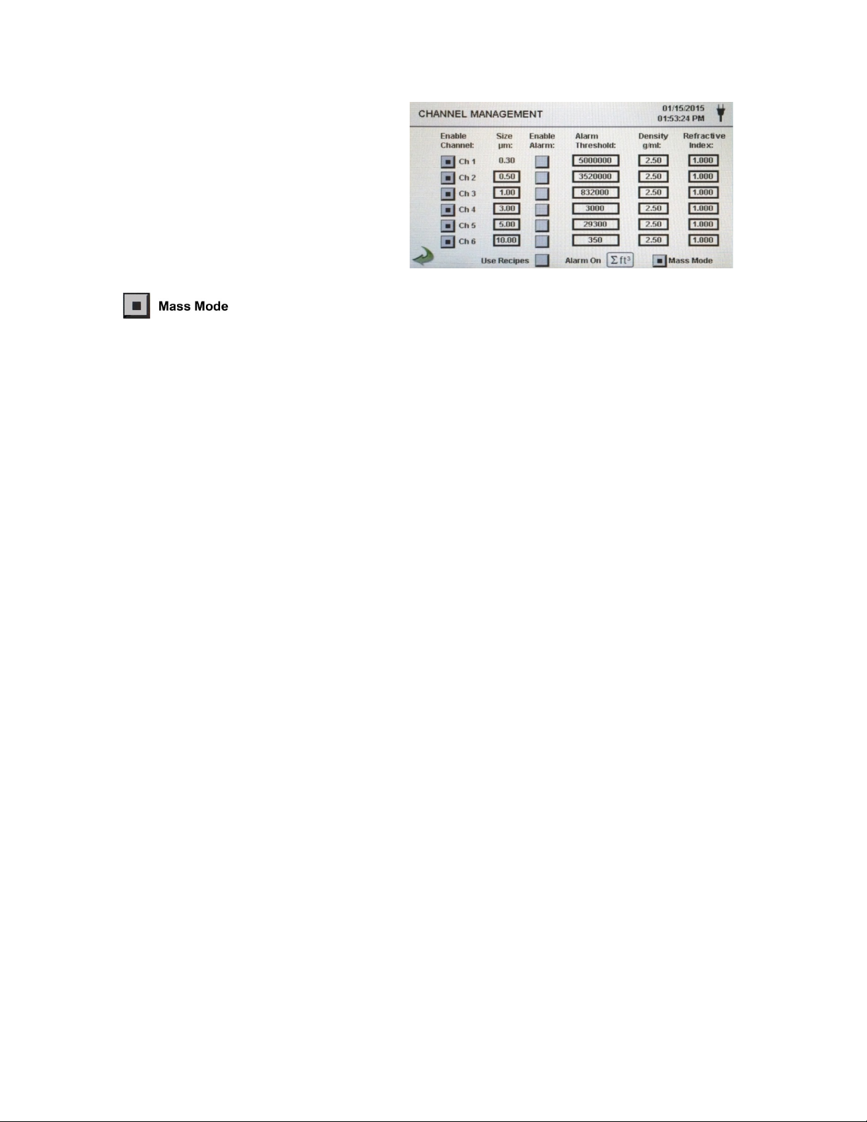
6-3 Channel Management
Enable Channel:
Each channel can be turned on or off by pressing the
Size
The individual channels (2 - 6) can have their target size
Enable Alarms
Each channel can have an alarm enabled or disabled by
Alarm On
By selecting the Cumulative Mode Icon the Channel Alarm
Channel Alarm
Δ - Differential count, Δft³ - Differential cubic feet,
micrograms per cubic meter,
Channel
Screen
This screen allows for many rich features to be controlled, including enabling or
disabling channels, setting custom channel sizes, enabling or disabling alarms by
channel and the setting of the alarm thresholds. The mass concentration mode may
also be activated to allo w entry of particle density and refractive index values by
channel.
Management
(micron - µm)
corresponding radio button. When the channel is turned
off all values related to that channel are ignored and will
not be displayed or recorded.
adjusted, by pressing the corresponding Size µm field and
entering the desired value with the numeric keypad.
This feature is also known as variable binning, and is ideal
for focusing on specific, known particle sizes.
pressing the selection button for the channel. The Alarm
Threshold can be entered by pressing this field and
entering a numerical value on the Enter Alarm Threshold
Screen. This displays a numeric touchpad in order to enter
the desired value. Once the value is entered, click ok, or
cancel to return to the Channel Management screen.
Setup Page
Setup Screen is displayed. The Alarm On Threshold
values will correspond to the eight (8) options listed on the
Channel Alarm Setup page.
Δm³ - Differential cubic meter, Σ - Cumulative count,
Σft³ - Cumulative cubic feet, Σm³ - Cumulative cubic
meter, µg/m3 or PM - Particle Mass
33
Page 33
6-3 Channel Management (continued)
Mass Mode
The Mass Mode button allows the instrument to display
Density g/ml:
The density of the particles to be measured can be entered
Refractive
The refractive index of the particles to be measured can be
µg/m3
When Mass Concentration Mode is selected, µg/m3 is the
Particle Mass
The column labeled PM shows the total particle mass of
as PM2.5.
Mass Mode
Settings
Enable
Index
Calculation of displayed Values on Main Screen for Mass Concentration Mode
Indicated
Values
Explained
particle count data as calculated particle mass
concentration in weight/volume units. The international SI
unit for mass is (kg/m3), which can be translated to micro
grams per milliliter (µg/ml) This is indicated as an accepted
value for particle mass monitoring for environmental as
well as health & safety applications.
to allow for higher accuracy and correlation to the actual
mass concentration values. To do so, select the numeric
field corresponding to the particle size channel and enter
the desired density value in g/ml with the numeric touch
pad. Press OK or cancel to return to the Channel
Management Screen.
entered in mass concentration mode. To do so, select the
numeric field corresponding to the particle size channel
and enter the desired density refractive index value with
the numeric touch pad. Press OK or cancel to return to the
Channel Management Screen.
measured value in the first column. The mass value for a
channel size is the particle count between that channel and
the next larger channel, calculated using the average
particle size of the two channels. For example, the value in
the 0.50 µm data field represents the mass of all particles
counted between this channel and the next highest
channel, calculated as the mass of a particle that is 0.75
µm.
Indicated
Valued
Explained
particles that are less than the displayed channel size. For
example, the value displayed in the PM column for the
2.5µm channel is the particle mass (µg/m³ column) of all
particles with a size less than 2.5µm, generally referred to
34
Page 34

6-4 Locations & Recipes
Location Auto
When a sample is completed and the instrument is set to
Navigate up or
Navigate with the up and down white arro ws on the right
Move Selected
Move the selected location up or down using the Silver
New Location
Press the New button to create a new location on the
Edit Location
Press the Edit button to modify the location highlighted
Remove Location
Press the Remove button to delete the currently
Pressing the Locations Icon opens the Select Location & Recipes screen. Up to
1000 unique location names can be created. This screen also provides for
Location-specific recipes which utilize preset sample times, delays, hold times,
cycles, etc. Over 50 unique recipes can be created to correspond to any number
of locations.
Select Location &
Recipe Screen
Advance
down through
location list
Location Up /
Down through
List Order
Entry
automatic mode, Pressing this button auto advances to
the next location.
side of the list. The red slider button can also be pressed
and dragged up or down with a stylus or finger to
navigate quickly up and down the list.
and Green up and down arrow buttons on the left side of
the locations list. Locations can be moved in order to
group common areas to be tested for more convenient
selection during setup, prior to a sampling event.
Location list. Selecting this button will display the Enter
Name For New Location screen. Use the touchscreen
keyboard to enter the name of the new location. Press
OK to return to the previous screen.
on the Location list. Selecting this button will display the
Enter New Name For Location screen. Use the
touchscreen keyboard to modify the name of the existing
location. Press OK to return to the previous screen.
highlighted location.
35
Page 35

6-4 Locations & Recipes (continued)
Use Recipes
Pressing this button displays the Recipes settings
Edit Recipe for
Press the Edit button on lower right hand side of screen
New Recipe Entry
Press the New button to create a new recipe. The Enter
Edit Recipe
Press the Edit button to modify the existing recipe
Remove Recipe
Press the Remove button to delete the recipe that is
Used By Tab
The Used By window displays all locations currently set
portion of the page. By selecting the Location on the left
box, then setting the recipes from the right box, the
location is configur ed with one of 50 possible user
defined sampling setups.
Selected Location
Recipe Information
Appears on Right
Side of Screen
The instructions that follow are related to the illustration on the top of page 36
under recipe setup window, to enter the Recipe setup.
Name For New Recipe screen will appear. Use the
touchscreen keyboard to enter the name of the new
recipe. Press OK to return to the previous screen.
highlighted on the Location list. Press ing this button will
display the Enter New Name For Recipe screen. Use
the touchscreen keyboard to modify the name of the
existing recipe. Press OK to return to the previous
screen.
highlighted on the Location list.
to use the current recipe when sampling.
36
Page 36

6-4 Locations & Recipes (continued)
Edit 1 Tab
The Edit 1 tab allows for the sampling settings, including
be set for that recipe.
minutes and 59 seconds.
minutes and 59 seconds.
per sample to achieve the desired sample volume.
the event.
59 minutes and 59 seconds.
Edit Recipe Tab 1 Delay
the delay time, sampling time, cycles and mode that can
Pressing the Delay time box opens the Enter Time
screen. The numeric touchpad is used to enter the
amount of time the counter will wait before starting a
sample in automatic mode.
The entry is made in Hours:Minutes:Seconds
(HH:MM:SS). The maximum delay time is 99 hours, 59
Edit Recipe Tab 1 Sample
Edit Recipe Tab 1 Volume
Edit Recipe Tab 1 Sample or Volume
selection buttons
Edit Recipe Tab 1 Hold
Pressing the Sample Button opens the Enter Time
screen with numeric touchpad for the entry of the amount
of time the counter w ill sample in automatic mode.
The entry is made in Hours:Minutes:Seconds
(HH:MM:SS). The maximum sample time is 99 hours, 59
Pressing Volume displa ys the numeric touchpad for the
entry of the desired volume to be sampled. The volume
will correspond to the units selected in the Sample
Volume Units Selection on the Sample Setup Screen.
The volume value entered will control the length of time
Selecting Sample will cause the sample to be time based
on the Sample time value entered. Selecting Volume will
cause the sample to be based on the actual volume of air
sampled to be measured and achieved before finishing
Pressing the Hold Button opens the Enter Time screen
with numeric touchpad for the entry of the amount of time
the counter will hold between samples in automatic
mode.
The entry is made in Hours:Minutes:Seconds
(HH:MM:SS). The maximum Hold delay time is 99 hours,
37
Page 37

6-4 Locations & Recipes (continued)
Edit Recipe Tab 1 Cycles
Pressing Cycles displays the Enter Cycles Screen with
Edit Recipe Tab 1 Mode
The Mode icon opens the Select Sample Mode page.
Edit Recipe Tab 2 Select Channel Alarm
Select the channels to activate the alarm threshold values
Back Arrow Icon
Press back to last screen arrow on bottom left corner of
numeric touchpad for entry of the number of sampling
cycles to be taken at a specific location when the unit is in
automatic mode.
Enter ZERO (0000) to activate Continuous Sampling
Mode.
Select Automatic mode or Manual Mode. After making a
selection, press OK to accept and return to the previous
page, or select cancel.
set in the Channel Management Screen.
the display to return to the last screen, repeat this action
to return to the settings screen or twice to return to the
main home screen.
38
Page 38

6-5 Configuration
Language
Select and highlight the language to be used with your
Store Partial
Select this option to save values from a prematurely ended
Alarm
During an alarm, the visual alarm bell and the audible
Enable
Selecting this option to allow annotations (notes) to be
Number Format
This selection box allows for setting the number formats:
Factory Restore
This option will display the Factory Restore screen. Use this
USB Icon
When a USB Thumb drive or mass storage device is
Pressing this Icon opens the Configuration screen. Various parameters can be set
from this page inc ludi ng la n guag e sett ings , US B conf igur atio n sa ve options , and
factory restore to default parameters.
Configuration Screen
device. English is the Default.
Samples
Acknowledge
Annotations
sampling. If this option is left unchecked, the Instrument will
ignore partial sampling events.
sounder will continue to sound until the alarm bell icon is
pressed when this option selected. If this option is not
selected, then the alarm sounder and visual alarm indicator
will function normally. Once the next sampling cycle starts
(in automatic mode) the alarm indications will reset
themselves.
entered on to the sample record while it is taking place, or
after the fact in the records history. These notes will be
included in downloaded record data. If this is unchecked, the
feature is disabled.
1,000.0 - 1.000,0 - 1 000,0
screen to restore Locations and Recipes, User Settings, and
Retain Language Settings. You must hit the Confirm button
to enact this feature.
plugged into the USB host port on the particle counter, the
USB Configuration Save/Load Icon appears on the right side
of the main Configuration screen. The Configuration
Load/Save feature allows for saving the current
configuration, including Recipes, locations and settings,
from the instrument to the thumb drive. The feature can be
used to restore the saved configuration back to any other
Setra Systems handheld Part icle Cou nter .
39
Page 39

6-5 Configuration (continued)
Settings to
Use the two check boxes to select Locations and Recipes or
Load Settings
This button initiates the loading of a previously saved settin gs
Save Settings
This button will save the current configuration settings to the
back arrow Icon
Press the back to last screen arrow on bottom left corner of
Automatic Printing
Selecting this option gives additional options to choose if
'On Alarm'
Include in Printout
Select each item of information to include with printed
Configuration
Load/Save Screen
Load/Save
6-6 Printer Setup
This screen allows for the configuration of your printing options.
User Settings for loading or saving with the USB thumb drive.
configuration into the current instrument.
attached thumb drive or mass storage device.
the display to return to the previous screen
the particle counter will print automatically 'On Sample' or
values and reports
40
Page 40

6-7 Communication
Wi-Fi
The particle counter can support an optional Wi-Fi
Wi-Fi SSID
Selecting this button allows for the entry of the name of the
Wi-Fi Password
Selecting this button allows for the entry of the password
these characters
Ethernet
The particle counter can support Ethernet RJ-45
connection to a network for communications.
IP Address, Subnet
Enter in the IP address for the device for your network
USE DHCP
Specifying this will allow the device to obtain an IP
The instrument has multiple modes of communication for uploading or downloading
data or configurations for operation. The modes of communication are Ethernet,
RS485, RS232, USB Host or Client, and Optional Wi-fi Communications.
Communications
Screen
Communication
Mask, & Gateway
Wi-fi Settings Screen
the Subnet mask and gateway for your router. A numeric
keypad will be displayed for entering these values.
address, subnet mask and gateway information from the
router automatically
communications module. If this is to be used select this
radio button, and input the IP address, Subnet Mask, and
Gateway. A numeric keypad will be disp layed for entering
these values.
wireless router or network ID in order to connect to that
router wirelessly. A keyboard will be displayed to allow for
entry of these characters
needed to access the wireless router on the network to be
used. A keyboard will be displayed to allow for entry of
41
Page 41

6-7 Communication (continued)
Modbus Address
Enter in the Modbus address for the device for your
TCP Port
Enter in the TCP Port for the device for your network, A
TCP
Enter in the TCP Configuration Port address for the device
Mode
Choose either ASCII, RTU or TCP
Baud
Select baud rate - 9600 / 19,200 / 38,400 / 57,600 /
Parity
Select Parity - Odd / Even / None
Register Set
Choose which register set to be communicated to your
IMPORTANT
The Setra Systems MODBUS register map can be found in
Internet of Things
The Setra Systems Instrument can communicate to remote
Modbus Settings
Screen
network, A numeric keypad will be displayed for entering
these values.
numeric keypad will be displa yed for enteri ng these va l ues .
Configuration
Port
NOTE:
(IOT)
for your network, A numeric keypad will be displayed for
entering these values.
115,200
network or monitoring system.
the Appendix at the back of this manual. Other Register
Maps to match your current system configuration are
available on request.
servers over a network or the Internet. The setup of this
JSON protocol for IOT can be found in the IMS software
communications settings options, while the instrument is
connected to the PC running IMS with the included USB
cable.
42
Page 42

6-8 Environment
Enable Alarms
Selecting the enable alarm function for Temperature or
Low Threshold
The low threshold value fields allow for the low threshold to
High Threshold
The High Threshold value fields allow for the high threshold
Units
This section allows for selection of metric or standard
The Environment screen allows for the setting of the temperature, humidity and
barometric pressure units, and to allow the instrument to activate an alarm
associated with the sensors.
Environment
Setting Screen
Relative Humidity will allow the instrument to indicate if a
low or high threshold for either environmental parameter is
exceeded or dropped below the minimum set threshold.
6-9 Passwords
The Password Setup Screen allows for the secure operation of the instrument by
authorized users, and configuration and setup changes by administrators in
accordance with 21 CFR 11.
Password Setup
Screen
be entered for either temperature, relative humidity, or
both. When the field is selected a numeric keypad appears
allowing for the values to be entered and saved.
to be entered for either temperature, relative humidity, or
both. When the field is selected a numeric keypad appears
allowing for the values to be entered and saved.
values for temperature and barometric pressure.
43
Page 43

6-9 Passwords (continued)
Admin Password
Selecting this radio butt on ac tivates the administrative
Admin Password -
The two password entry fields allow for the password to be
User Password
Selecting this radio button activates the user password
User Password -
The two password entry fields allow for the password to be
Password
Password timeout is the length of time in minutes there is
Lock Now
The lock now icon puts the instrument immediately to the
IMPORTANT
At any time during the operation of the particle counter,
If at any time the administrative password is lost or
password function for 21 CFR 1 compliance preventing any
settings, time/date, or configurations to be changed by
lower level users.
New Password /
Confirm New
Password
New Password /
Confirm New
Password
Timeout
NOTES
entered and saved. By selecting these fields it will bring up
an alpha-numeric keyboard allowing for the user to enter a
new administrator password. The default administrator
password from the factory is 4321
function preventing any unauthorized use of the particle
counter. User level access allows for using the instrument
in its current configuration, and saving samples.
entered and saved. By selecting these fields it will bring up
an alpha-numeric keyboard allowing for the user to enter a
new user level password. The default user password from
the factory is 1234
no activity on the particle counter. If the unit is operating
and inactive for more than the amount of time entered, the
next operation will require a User or Administrator
password to continue. The default is 5 minutes.
password enter screen. No activity is possible without
entering the password to unlock the particle counter.
while passwords are active, the administrative password
can be entered even if the user password is being
requested. This will cause the unit to allow all
administrative access to features, sett ings and
configuration changes screens.
forgotten, you can call or email Setra Systems for a
temporary password that will be valid only for that
day the password is requested. This is a unique
password that will automatically expire at the end of
the day it is issued. Due to 21 CFR 11 requirements,
proof of ownership and administrative rights will
need to be established.
44
Page 44
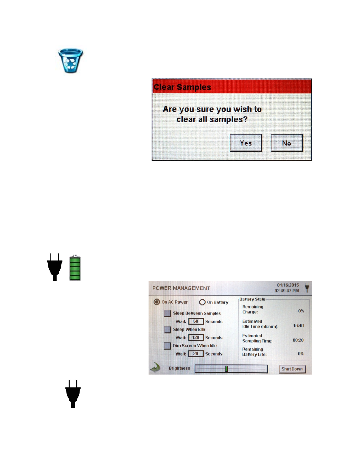
6-10 Clear All Samples
Confirmation
By selecting the Clear Samples Icon in the Settings Screen,
All records on the instrument can be cleared with this function. CAUTION – This is
not reversible and all data will be lost. Back up all data to a PC or USB Memory
device before using this function. This function is found in the Sample Settings Menu.
Screen
7-1 Power Management
The instrument utilizes advanced power management functions that are unique to
Setra Systems. Please be certain to read the battery and power safety instructions at
the beginning of this manual.
Power Management
Screen
the confirmation screen will appear asking if the request
should be completed. Selecting Yes will delete all recorded
samples. Selecting No returns the display to the settings
screen.
AC Adapter Icon This Icon is visib le w hen the instrument is plugged into AC
mains power and pressing this icon brings you to the Power
management screen.
45
Page 45

7-1 Power Management (continued)
Battery Level
This icon also allows for access to the Power Management
Icon
The battery power level icon will display differently depending
The Power Level Indication is displayed as follows:
Remaining
(0 to 100%) - this is the percent of battery life left for this
Estimated Idle
(hours:minutes) - this is the amount of time in hours and
Estimated
(hours:minutes) - this is the amount of time in hours and
Remaining
This is a percent indication of the total life left on this battery
On AC Power
When Selected, all dimming timers, sleep mode timers and
On Battery
When Selected, all dimming timers, sleep mode timers and
Sleep Between
Selecting this button activates the feature for power down
Indicator/Icon
Charge
Time
Sampling Time
Battery Life
screen, and also serves as a visual indication of the battery’s
power level
on the amount of battery power that is left in a percentage
(20% to 100%)
100% 80% 60% 40% 20%
current charge displayed as a percent
minutes left for this current battery charge if the unit remains in
the on power state, and without sampling.
minutes left for this current battery charge if the unit is on, the
pump is running and the unit is sampling.
pack during the life of the battery. This is useful for monitoring
when to replace your power cells.
Option
Option
Samples
screen brightness bar settings will be valid when the unit is
plugged into mains power using the AC adapter.
screen brightness bar settings will be vali d when the u nit is not
attached to mains power and operating on the removable
internal batteries.
operation to conserve battery life. A timer window will appear,
allowing for the input value of the amount of time, after
completing a sample, before the system will go to sleep. This
value is input by selecting the time input window box. This will
bring up the numeric keypad allowing for the input, in seconds
from 30 to 65,535 seconds. after entering value press ok to
return to last screen. (Please note that the minimum time
possible for the sleep mode will be 30 seconds, and if sampling
delay time is also selected, that time is automatically added to
this value.)
46
Page 46

7-1 Power Management (continued)
Sleep When Idle
Selecting this button activates the timer box for this option to
Dim Screen
Selecting this button allows the instrument to save power by
Brightness
Selecting the slider green vertical cross bar, move the slider to
Shutdown Icon
Power down the instrument through the interface immediately
Back Arrow Icon
Press back to last screen arrow on bottom left corner of the
Volume
By selecting the icon a volume slider control appears. Select the
value of the volume level appears at the bottom of the slider.
Option
When Idle
Select Slider
count the number of seconds after the unit is idle, with no
activity, to go into sleep mode conserving battery power.
The amount of time to wait before going to sleep is entered by
selecting the time input window box. This will bring up the
numeric keypad allowing for the input of the idle time value, in
seconds from 1 to 65,535 seconds. After entering the value
press ok to return to last screen. (Please note that the default
value is 120 seconds.)
dimming the display brightness after the touch screen is not
pressed for the selected time. The amount of time to wait
before dimming the screen is entered by selecting the time
input window box for this option. This will bring up the numeric
keypad allowing for the input of the wait to dim screen when
idle time value, in seconds, from 20 to 65535 seconds. After
entering the value press ok to return to last screen. (Please
note that the default value is 20 seconds.)
the left to decrease and to the right to increase the screen
brightness.
with this icon. The instrument can also be turned off from the
power switch on the handle.
display to return to main home screen.
8-1 Volume Controls
Control Icon
bar on the slider and increase or decrease the volume.
Decreasing the slider to zero, mutes the speaker. A numerical
47
Page 47

9-1 Instrument Management Software (IMS)
Load/Install
To load the Setra S ystem s Comm unic ation Sof t ware, install the
Start Software
Use the Setra Systems IMS Icon in the program folder or from
Connection
When the meter is connected to the PC by the provided USB
The particle counter also includes a PC based software utility that allows for the
remote access to download data, field calibration for sensors, upload firmware
updates, remote diagnostics direct to a service technician, and Real-Time Graphing
remotely controlling the instrument over a USB or Ethernet Cable.
Please note that detailed instructions for the use of the IMS software are
contained in the IMS Software Manual on the included USB thumb drive.
to PC
provided thumb drive in to your PC with the Windows (7™, 8™
and 10™) operating system. Open the thumb drive folder and
select the web installer application file. Follow the installation
prompts. Allow permissions with your PC and virus protection
software during the installation process.
the desktop to start the program.
(Communication Software Main Screen Window Shown Above)
Indication
cable, and the software has successfully linked with the device,
a Green USB Connection indication will appear on the bottom
left side of the program window. A No Connection in di c ation will
be displayed when no device is connected or detected.
48
Page 48
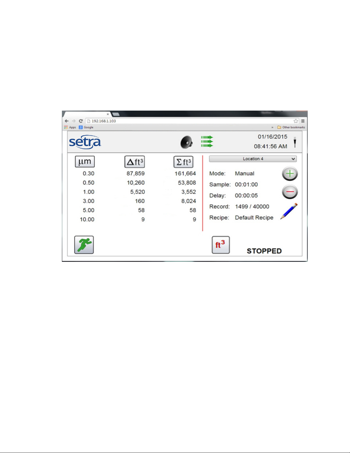
10-1 Particle Counter Host Mode – Remote Monitor and Operation
Access your
The Setra Systems particle counters can host and provide a
screen
The Instrument can have the sampling started, and stopped, It
corresponding icons.
enter that into any device browser to access the remote screen.
particle counter
from a web
browser from
any PC, Tablet or
smartphone
browser based remote operation interface session. With
advanced processing there can be many remote access
sessions taking place concurrently with the unit still operating
and recording samples. This is achieved through a built in web
server software. This allows for direct communication through a
local intranet (connected by Ethernet or Wi-Fi), using the
instrument’s IP address found in the communications setup
10-1 PC Communication Software (continued)
provides a full visual indication of the home page display, the +
The Functions of
Remote Web
Based Operation.
Connecting
using Ethernet or
Wi-Fi
& - keys can allow the remote user to scroll through and select
different locations to utilize; The Units can be changed from
Count, to CNT/M3, CNT/F3, or µg/m3. The value columns for
cumulative or differential can be turned on and off using the
The Instrument must be placed in Ethernet or optional Wi-Fi
mode to allow for this feature, and the unit must also be
connected to a working router on the same network as the PC.
In the Communications Setup page, select apply settings with
the use DHCP button selected, and the unit will autom atica lly
display the router issued settings to allow connection. Use that
IP address that is saved on the Communication page, and
Note: the URL address is the IP address that the DHCP Router assi gne d to the Par ticle Counter. You
can also provide a static IP address for the device through the communications setup screen and with
access to your router’s administrative functions to set a static IP in the client tables.
49
Page 49

Appendix – A
The MODBUS Register Map can be found on the USB memory stick as a separate PDF document file.
50
Page 50

SS-SPCMN-24001P Rev. A 02/2018
 Loading...