

Page 1

Page 2

S 411/415 HD, S 415 HDC, S 415/416/417 HDH/04.2012 GB
1
Page 3

04.2012 EvoBus GmbH
Not to be reprinted, reproduced or translated in any form without prior permission.
Address for orders:
EvoBus GmbH
Service Documentation
D-89077 Ulm, Germany
Printed in Germany
Order no.:
A 629 584 53 73
Page 4

Introduction
The user information supplied with
each bus is intended for use only
by persons who are qualified to
operate the bus. The user
information is split into the
following parts:
The Driver's Operating Instructions
are intended to answer all important questions concerning operation
of the bus in a concise and clearly
understandable manner.
More detailed and complete information, as well as further information
relevant to safety, can be found in
the Operating Instructions.
The Maintenance Record serves as
a guide to the technical care of the
bus. It contains all the information
on maintenance intervals and maintenance tasks as well as pages for
confirming that the maintenance
work has been carried out.
Please make sure that you read the
“Safety” section before you use the
vehicle for the first time. Before the
bus is driven, please make sure that you
have read and understood the contents
of these Operating Instructions.
Items of optional equipment are also described, if their operation needs explanation. The bus delivered to you has been
customised in accordance with your order, therefore some descriptions and
diagrams may differ from the equipment
on your bus.
The Driver's Operating Instructions, the
Operating Instructions and the Maintenance Record are important documents
and must always be carried in the bus.
Our buses are the subject of ongoing
development. You are therefore asked
to appreciate that we reserve the right
to make modifications to the design,
equipment and technical features. For
these reasons, no claims can be made
based upon the contents of this user
information.
Environmental protection
The declared policy of EvoBus GmbH
is one of integrated environmental protection. This policy starts at the root
causes and encompasses in its management decisions all the consequences for
the environment which could arise from
production processes or the products
themselves.
The objectives are for the natural resources which form the basis of our existence on this planet to be used sparingly and in a manner which takes the
requirements of both nature and humanity into account.
Operate your vehicle in an environmentally responsible manner and you will help
to protect the environment. Fuel consumption and wear in the drive train (engine, clutch, transmission, axles, brakes,
tyres) are extremely dependent on your
driving style.
We hope you enjoy driving your bus.
EvoBus GmbH
Page 5

Setra Omnibusse
Page 6

Table of contents
Vehicle identification . . . . . . . . . . . 1
Safety . . . . . . . . . . . . . . . . . . . . . . . 3
The use of symbols and their mean-
ings . . . . . . . . . . . . . . . . . . . . . . . . . 4
Notes on vehicle safety . . . . . . . . . . . 4
Operating safety . . . . . . . . . . . . . . . . 5
EU Directive 2001/85 . . . . . . . . . . . 5
Stickers . . . . . . . . . . . . . . . . . . . . . . 6
Navigation and global positioning
system . . . . . . . . . . . . . . . . . . . . . . 6
Operation of the radio and mobile
communications equipment . . . . . . . . 7
Operation of mobile phones and
radio equipment without an exterior
aerial . . . . . . . . . . . . . . . . . . . . . . . . 7
Washing the outside of the bus in an
automatic vehicle wash . . . . . . . . . . . 8
Storage space for hand luggage . . . . . 9
Driver's rest area safety precau-
tions . . . . . . . . . . . . . . . . . . . . . . . . 9
Windscreen wiper system safety
precautions . . . . . . . . . . . . . . . . . . . 9
Safety precautions for the air-
conditioning system . . . . . . . . . . . . 10
Operation of auxiliary heating . . . . . 10
General . . . . . . . . . . . . . . . . . . . . . 13
Preparation for the journey - daily
tasks . . . . . . . . . . . . . . . . . . . . . . . 14
Preparation for the journey - weekly
tasks . . . . . . . . . . . . . . . . . . . . . . . 15
Preparation for the journey - monthly
tasks . . . . . . . . . . . . . . . . . . . . . . . 16
Additional maintenance tasks
dependent on bus use . . . . . . . . . . 16
General bus care and mainten-
ance . . . . . . . . . . . . . . . . . . . . . . . 16
Care and cleaning . . . . . . . . . . . . . . 17
Operation . . . . . . . . . . . . . . . . . . . 19
Running-in guideline . . . . . . . . . . . . 22
Starting the engine . . . . . . . . . . . . . 22
Driving . . . . . . . . . . . . . . . . . . . . . . 24
Stopping the engine . . . . . . . . . . . . 25
Towing and tow-starting . . . . . . . . . 26
Trailer towing . . . . . . . . . . . . . . . . . 29
Loading a trailer . . . . . . . . . . . . . . . 30
Driving with a trailer . . . . . . . . . . . . 30
Ball hitch trailer coupling (fixed)
(option) . . . . . . . . . . . . . . . . . . . . . 31
Ball hitch trailer coupling and
open-jaw trailer coupling (detachable)
(option) . . . . . . . . . . . . . . . . . . . . . 32
Connecting the power supply . . . . . 32
Trailer coupling maintenance . . . . . . 33
Refuelling (diesel fuel) . . . . . . . . . . . 33
BlueTec exhaust gas cleaning
system . . . . . . . . . . . . . . . . . . . . . 35
AdBlue service product . . . . . . . . . . 37
Filling with AdBlue . . . . . . . . . . . . . 39
Operating/malfunction displays: fuel
system . . . . . . . . . . . . . . . . . . . . . 41
Function of the accident data
recorder (ADR) (option) . . . . . . . . . . 44
Brake system safety precautions . . . 45
Emergency braking . . . . . . . . . . . . . 45
Braking and stopping . . . . . . . . . . . 46
Brakes with anti-locking protec-
tion . . . . . . . . . . . . . . . . . . . . . . . . 46
Applying the parking brake . . . . . . . 47
Releasing the parking brake . . . . . . 48
S 411/415 HD, S 415 HDC, S 415/416/417 HDH/04.2012 GB
I
Page 7

Table of contents
Emergency braking in the event of
failure of both brake circuits . . . . . . 48
EBS brake system . . . . . . . . . . . . . 49
Acceleration skid control (ASR) . . . . 50
Brake Assist . . . . . . . . . . . . . . . . . . 50
Adaptive brake lamps . . . . . . . . . . . 50
Electronic Stability Program (ESP)
(system description) . . . . . . . . . . . . 51
Electronic Stability Program (ESP)
(function description) . . . . . . . . . . . 52
Deactivating the Electronic Stability
Program (ESP) . . . . . . . . . . . . . . . . 54
Operating/malfunction displays:
brake system . . . . . . . . . . . . . . . . . 54
Operating 230/400 V systems
(option) . . . . . . . . . . . . . . . . . . . . . 61
Fitting the skibox (option) . . . . . . . . 62
Swivelling the skibox (option) . . . . . 64
Further skibox (option) operating
instructions . . . . . . . . . . . . . . . . . . 65
Note on maintenance work . . . . . . . 65
Cleaning the underbody . . . . . . . . . 66
Care and cleaning . . . . . . . . . . . . . . 70
Care/cleaning of light-alloy
wheels . . . . . . . . . . . . . . . . . . . . . . 72
Care and cleaning of covers and
upholstery . . . . . . . . . . . . . . . . . . . 73
Care/cleaning of fabric covers . . . . 73
Care/cleaning of micro-fibre
covers . . . . . . . . . . . . . . . . . . . . . . 74
Care/cleaning of leather covers . . . . 76
At a glance . . . . . . . . . . . . . . . . . . 79
Driver's area overview . . . . . . . . . . . 82
Switches on the left section of the
instrument panel . . . . . . . . . . . . . . 83
Switches on the right section of the
instrument panel . . . . . . . . . . . . . . 88
Instrument cluster . . . . . . . . . . . . . 90
DTCO tachograph . . . . . . . . . . . . . . 92
Tachograph (display) . . . . . . . . . . . . 94
Door pushbuttons in the driver's
area . . . . . . . . . . . . . . . . . . . . . . . 94
Location of tools and emergency
equipment on the bus . . . . . . . . . . . 95
Location of the fire extinguish-
ers . . . . . . . . . . . . . . . . . . . . . . . . 96
Location of the first-aid kits . . . . . . 96
Tow bar location (option) . . . . . . . . 97
Location of the replacement mirror
(option) . . . . . . . . . . . . . . . . . . . . . 97
Reversing aid display in the exterior
mirror (option) . . . . . . . . . . . . . . . . 97
Emergency hammer (option) . . . . . . 99
Driver's rest area (bus with
roof-mounted air-conditioning
system) . . . . . . . . . . . . . . . . . . . . 100
Driver's rest area (bus with TopAir integrated air-conditioning
system) . . . . . . . . . . . . . . . . . . . . 102
Windscreen washer reservoir . . . . . 104
Reversing camera washer fluid
reservoir (option) . . . . . . . . . . . . . 106
Seat belt reminder display . . . . . . . 107
Exterior flaps on S 411 HD . . . . . . 108
Exterior flaps on S 415 HD . . . . . . 110
Exterior flaps on S 415/416/417
HDH . . . . . . . . . . . . . . . . . . . . . . 112
Layout and function description: fire extinguishing system
(option) . . . . . . . . . . . . . . . . . . . . 113
Fire extinguishing system operating
and malfunction displays . . . . . . . . 114
Driver's area controls . . . . . . . . . 115
Ignition switch . . . . . . . . . . . . . . . 119
Adjustable steering column . . . . . . 119
II
S 411/415 HD, S 415 HDC, S 415/416/417 HDH/04.2012 GB
Page 8

Table of contents
Exterior lighting . . . . . . . . . . . . . . 120
Steering column switch for light
and wiper functions . . . . . . . . . . . 123
Steering column switch for retarder
and cruise control (overview) . . . . . 125
Overview of steering wheel buttons
and display screen . . . . . . . . . . . . 132
Steering wheel buttons . . . . . . . . . 133
Display screen . . . . . . . . . . . . . . . 134
Display screen (description) . . . . . . 135
Permanent displays . . . . . . . . . . . . 136
Trailer turn signals . . . . . . . . . . . . 137
Overview of main menus and
submenus . . . . . . . . . . . . . . . . . . 138
Menu structure . . . . . . . . . . . . . . . 139
Display screen menu control
logic . . . . . . . . . . . . . . . . . . . . . . 146
Event notifications . . . . . . . . . . . . 148
Instrument cluster buttons . . . . . . 152
Resetting the trip meter . . . . . . . . 153
RESET button (to reset trip
computer data) . . . . . . . . . . . . . . . 153
Menu button . . . . . . . . . . . . . . . . 155
DIAG button (on-board dia-
gnostics) . . . . . . . . . . . . . . . . . . . 155
SET button . . . . . . . . . . . . . . . . . . 156
Setting the language . . . . . . . . . . . 156
Adjusting the volume of the turn
signal buzzer . . . . . . . . . . . . . . . . 158
Setting the wipe interval/rain
sensor sensitivity . . . . . . . . . . . . . 159
Setting the courtesy lighting
switch-on duration . . . . . . . . . . . . 160
Switching the daytime driving lights
on/off . . . . . . . . . . . . . . . . . . . . . 162
Activating the transmission shift
system failsafe mode (GO 240-8
PowerShift) . . . . . . . . . . . . . . . . . 163
Adjusting the display brightness
(daytime brightness) . . . . . . . . . . . 164
Adjusting the display brightness
(night brightness) . . . . . . . . . . . . . 165
Right-hand steering wheel but-
tons . . . . . . . . . . . . . . . . . . . . . . 168
Volume adjustment . . . . . . . . . . . . 169
Radio volume adjustment . . . . . . . 170
Driver's area on-board PA system
volume adjustment . . . . . . . . . . . . 171
Adjusting the volume of the intercom in the driver's rest area/
on-board kitchenette . . . . . . . . . . . 172
Telephone volume adjustment . . . . 173
Initiating an outgoing call using
the driver's rest area/kitchenette
intercom (option) . . . . . . . . . . . . . 174
Initiating an outgoing call using the
driver's area intercom (option) . . . . 174
Answering an incoming call using the driver's area intercom
(option) . . . . . . . . . . . . . . . . . . . . 176
Mobile phone Bluetooth link . . . . . 177
Initiating an outgoing call using a
mobile phone (option) . . . . . . . . . . 179
Answering an incoming call using a
mobile phone (option) . . . . . . . . . . 181
Operating/malfunction displays:
telephone (intercom) . . . . . . . . . . . 182
Parking brake and emergency
release device . . . . . . . . . . . . . . . 183
Air suspension safety precau-
tions . . . . . . . . . . . . . . . . . . . . . . 184
Raising/lowering the bus . . . . . . . 184
Normal level . . . . . . . . . . . . . . . . . 185
Operating/malfunction displays:
level control . . . . . . . . . . . . . . . . . 186
Activating and deactivating the
trailing axle axle load transfer . . . . 187
Activating/deactivating the bus
stop brake (option) . . . . . . . . . . . . 188
S 411/415 HD, S 415 HDC, S 415/416/417 HDH/04.2012 GB
III
Page 9

Table of contents
Drive-off lock at door II with hinged
step (HDH only) . . . . . . . . . . . . . . 189
Important notes on the steering
system . . . . . . . . . . . . . . . . . . . . 190
Turning the steering wheel when
the bus is stationary . . . . . . . . . . . 190
Switching on the panorama camera
(option) . . . . . . . . . . . . . . . . . . . . 191
Switch descriptions . . . . . . . . . . 193
Master safety switch (emergency-off
switch) (national variant) . . . . . . . . 196
Switch for windscreen roller
sunblind (option) . . . . . . . . . . . . . 197
Switch for co-driver's roller sunblind
(option) . . . . . . . . . . . . . . . . . . . . 197
Switch for upper wiper (option) . . . 198
Driver's area lighting switch . . . . . 198
Attendant call system switch
(option) . . . . . . . . . . . . . . . . . . . . 198
Passenger stop request system
enable switch (option) . . . . . . . . . . 199
Club corner lighting switch
(option) . . . . . . . . . . . . . . . . . . . . 199
Reading lamps switch . . . . . . . . . . 199
Centre aisle lighting switch . . . . . . 200
Passenger-compartment lighting
switch positions I+II . . . . . . . . . . . 200
Switch for school bus operation
(option) . . . . . . . . . . . . . . . . . . . . 200
Headlamp cleaning system OFF
switch . . . . . . . . . . . . . . . . . . . . . 201
Horn changeover switch (op-
tion) . . . . . . . . . . . . . . . . . . . . . . 201
Kitchenette enable switch (op-
tion) . . . . . . . . . . . . . . . . . . . . . . 201
Lavatory enable switch (option) . . . 202
Switch for electrical circuits > 100
V (option) . . . . . . . . . . . . . . . . . . 202
Active Brake Assist OFF pushbutton
(option) . . . . . . . . . . . . . . . . . . . . 202
Switch for the driver's window
heating/mirror heating . . . . . . . . . 203
Windscreen heating switch
(option) . . . . . . . . . . . . . . . . . . . . 203
Central locking switch for the
left-side luggage compartment . . . . 204
Central locking switch for the right-
side luggage compartment . . . . . . 204
Neutral gearshift pushbutton . . . . . 204
Driver's power window pushbut-
ton . . . . . . . . . . . . . . . . . . . . . . . 205
PA system switch . . . . . . . . . . . . . 205
Lane assistant warning system
pushbutton (option) . . . . . . . . . . . 205
Bus stop brake emergency release
switch (option) . . . . . . . . . . . . . . . 206
Mirror adjuster . . . . . . . . . . . . . . . 206
Door I pushbutton . . . . . . . . . . . . 207
Door II pushbutton . . . . . . . . . . . . 208
Switch for deactivating pedal-
activated continuous braking . . . . . 208
Axle load transfer switch (3-axle
buses only) . . . . . . . . . . . . . . . . . 209
Electronic Stability Program (ESP)
OFF pushbutton . . . . . . . . . . . . . . 209
Hazard warning lamps pushbut-
ton . . . . . . . . . . . . . . . . . . . . . . . 209
Bus stop brake pushbutton
(option) . . . . . . . . . . . . . . . . . . . . 210
Pushbutton for reversing camera
washer system (option) . . . . . . . . . 210
Roof hatch switch - air in/air
out . . . . . . . . . . . . . . . . . . . . . . . 211
Multichannel system switch
(option) . . . . . . . . . . . . . . . . . . . . 211
Reverse warning buzzer switch
(option) . . . . . . . . . . . . . . . . . . . . 212
IV
S 411/415 HD, S 415 HDC, S 415/416/417 HDH/04.2012 GB
Page 10

Table of contents
Pushbutton for raising/lowering the
bus . . . . . . . . . . . . . . . . . . . . . . . 212
Normal-level pushbutton . . . . . . . . 212
Tank changeover switch (op-
tion) . . . . . . . . . . . . . . . . . . . . . . 213
Driver’s seat/passenger
seats . . . . . . . . . . . . . . . . . . . . . 215
Driver’s seat safety precau-
tions . . . . . . . . . . . . . . . . . . . . . . 216
Grammer driver's seat controls . . . 218
ISRI 6860/875 driver's seat control
elements (option) . . . . . . . . . . . . . 220
Operation of the jump seat . . . . . . 222
Using the driver's seat belt . . . . . . 223
Operating the jump-seat seat
belt . . . . . . . . . . . . . . . . . . . . . . . 223
Passenger-compartment-seating
seat belt . . . . . . . . . . . . . . . . . . . 224
Adjusting a passenger seat (new
seat generation) . . . . . . . . . . . . . . 224
Removing a seat squab (new seat
generation) . . . . . . . . . . . . . . . . . 225
Fitting a seat squab (new seat
generation) . . . . . . . . . . . . . . . . . 225
Passenger seat service set . . . . . . 226
Transmission shift systems . . . . 229
Transmission shift system safety
precautions . . . . . . . . . . . . . . . . . 230
Operating the PSH (pneumatic shift
aid) transmission shift system . . . . 230
ZF-AS TRONIC transmission shift
system (option) safety precau-
tions . . . . . . . . . . . . . . . . . . . . . . 231
ZF-AS TRONIC transmission shift
system (option) overview . . . . . . . . 232
ZF-AS TRONIC transmission
shift system (option) (system
description) . . . . . . . . . . . . . . . . . 233
Operating the ZF-AS TRONIC trans-
mission shift system (option) . . . . . 234
ZF-AS TRONIC transmission shift
system operating/malfunction
displays . . . . . . . . . . . . . . . . . . . . 246
GO 240-8 PowerShift transmission shift system (option) (system
description) . . . . . . . . . . . . . . . . . 250
GO 240-8 PowerShift transmission
shift system (option) gearshift unit
(selector lever) . . . . . . . . . . . . . . . 252
Operation of the GO 240-8
PowerShift transmission shift
system (option) . . . . . . . . . . . . . . 253
Operation of the GO 240-8
PowerShift failsafe mode using the
steering wheel keypad (option) . . . 264
Driving systems . . . . . . . . . . . . . 267
Driving systems (overview) . . . . . . 269
Automatic speed limiter . . . . . . . . 270
Automatic speed limiter (function
description) . . . . . . . . . . . . . . . . . 270
Variable speed limiter (Tem-
poset) . . . . . . . . . . . . . . . . . . . . . 271
Activating the variable speed limiter
(Temposet) . . . . . . . . . . . . . . . . . . 271
Drive/brake cruise control . . . . . . 274
Activating drive/brake cruise
control . . . . . . . . . . . . . . . . . . . . . 275
Distance cruise control (ART)
(option) . . . . . . . . . . . . . . . . . . . . 278
Distance sensor for distance cruise
control (ART) . . . . . . . . . . . . . . . . 279
S 411/415 HD, S 415 HDC, S 415/416/417 HDH/04.2012 GB
V
Page 11

Table of contents
Activating distance cruise control
(ART) (option) . . . . . . . . . . . . . . . . 280
Setting the specified distance . . . . 282
Vehicle ahead detected . . . . . . . . . 284
How to respond to a distance
warning . . . . . . . . . . . . . . . . . . . . 285
Operating/malfunction displays:
distance cruise control (ART) . . . . . 286
Active Brake Assist (ABA) (system
description) . . . . . . . . . . . . . . . . . 287
Activation/deactivation of Active
Brake Assist (automatic) . . . . . . . . 288
Activating Active Brake Assist (ABA)
(manually) . . . . . . . . . . . . . . . . . . 289
Deactivating Active Brake Assist
(ABA) (manually) . . . . . . . . . . . . . . 289
Sequence of events when emergency braking initiated by Active
Brake Assist (ABA) . . . . . . . . . . . . 292
Function description: warning levels
and emergency braking . . . . . . . . . 293
Operating/malfunction displays:
Active Brake Assist (ABA) . . . . . . . 297
Special driving situations with distance cruise control/Active Brake
Assist . . . . . . . . . . . . . . . . . . . . . 301
Important information on the
lane assistant warning system
(option) . . . . . . . . . . . . . . . . . . . . 305
Deactivating the lane assistant
warning system . . . . . . . . . . . . . . 307
Operating/malfunction displays:
lane assistant warning system . . . . 308
Heating/ventilation/air-condi-
tioning . . . . . . . . . . . . . . . . . . . . 311
Operating instructions for the air-
conditioning system . . . . . . . . . . . 312
Heating/ventilation/air-conditioning
(HVAC) control panel . . . . . . . . . . 314
Manually regulating the blower
speed in the driver's area . . . . . . . 317
Preselecting the passenger-
compartment temperature . . . . . . . 318
Manually regulating the blower
speed in the passenger compart-
ment . . . . . . . . . . . . . . . . . . . . . . 320
Activating the air-conditioning . . . . 321
Switching on air-recirculation mode
in the driver's area and passenger
compartment . . . . . . . . . . . . . . . . 322
Activating the reheat function . . . . 323
Activating the auxiliary heating
unit . . . . . . . . . . . . . . . . . . . . . . . 324
Programming auxiliary heating
switch-on times . . . . . . . . . . . . . . 325
Activating a programmed auxiliary
heating switch-on time . . . . . . . . . 328
Deactivating an activated switch-on
time . . . . . . . . . . . . . . . . . . . . . . 329
Programming the auxiliary heating
switch-on duration . . . . . . . . . . . . 330
Switches/controllers in the driver's
rest area (bus with roof-mounted
air-conditioning system) . . . . . . . . 332
Switches/controllers in the driver's
rest area (bus with TopAir integ-
rated air-conditioning system) . . . . 334
Opening/locking . . . . . . . . . . . . . 337
Anti-entrapment protection (reversing) in the door closing
direction . . . . . . . . . . . . . . . . . . . 338
Anti-entrapment protection
(reduced-power pushback) in the
door opening direction . . . . . . . . . 338
VI
S 411/415 HD, S 415 HDC, S 415/416/417 HDH/04.2012 GB
Page 12

Table of contents
Door II anti-entrapment protection
(reduced-power pushback) activated
by hinged step (HDH only) . . . . . . 339
Emergency operation of the doors
in the event of an electrical system
failure or CAN bus malfunction . . . 340
Operating/malfunction displays:
doors . . . . . . . . . . . . . . . . . . . . . 341
Unlocking the door circuit (using
the remote control, front right door
or driver's door front left) . . . . . . . 345
Unlocking the luggage compartment
flaps using the remote control . . . . 347
Unlocking the luggage compartment
flaps using the pushbuttons in the
driver's area . . . . . . . . . . . . . . . . . 347
Locking (using the remote con-
trol) . . . . . . . . . . . . . . . . . . . . . . . 348
Central locking system (system
description) . . . . . . . . . . . . . . . . . 350
Operating/malfunction displays:
central locking . . . . . . . . . . . . . . . 354
Emergency operation (depressurising the doors using the
emergency valves) . . . . . . . . . . . . 355
Emergency closing of the
doors . . . . . . . . . . . . . . . . . . . . . 357
Emergency unlocking of the luggage
compartment flaps in the event of a
compressed-air supply failure . . . . 359
Emergency exit through emergency
operation of the roof hatches . . . . 360
On-board kitchenette (op-
tion) . . . . . . . . . . . . . . . . . . . . . . 363
General information . . . . . . . . . . . 366
Instructions for operating a
microwave oven . . . . . . . . . . . . . . 367
Use for the intended purpose . . . . 369
Approved personnel . . . . . . . . . . . 369
First use of the galley . . . . . . . . . . 370
Switching on the galley . . . . . . . . . 371
Filling the fresh water tank inside
the bus . . . . . . . . . . . . . . . . . . . . 372
Filling the fresh water tank outside
the bus . . . . . . . . . . . . . . . . . . . . 374
Checking and cleaning the fresh
water filter . . . . . . . . . . . . . . . . . . 374
Drawing water from the water
tap . . . . . . . . . . . . . . . . . . . . . . . 375
Switching on the boiler . . . . . . . . . 376
Descaling the boiler . . . . . . . . . . . 377
Switching on the sausage heat-
er . . . . . . . . . . . . . . . . . . . . . . . . 379
Cleaning the sausage heater . . . . . 383
Descaling the sausage heater . . . . 383
Switching on the 40-cup coffee
machine . . . . . . . . . . . . . . . . . . . . 383
Brewing coffee in winter . . . . . . . . 387
Cleaning the 40-cup coffee
machine . . . . . . . . . . . . . . . . . . . . 388
Switching on the 2-carafe filter
system . . . . . . . . . . . . . . . . . . . . 389
Brewing 1/2 a carafe of coffee (10
cups of coffee) . . . . . . . . . . . . . . . 389
Brewing 1 carafe of coffee (20 cups
of coffee) . . . . . . . . . . . . . . . . . . . 390
Brewing 2 carafes of coffee (40
cups of coffee) . . . . . . . . . . . . . . . 391
Manual operation of the 2-carafe
filter system . . . . . . . . . . . . . . . . . 392
Descaling the coffee machine . . . . 392
Winter operation . . . . . . . . . . . . . . 394
Draining the fresh water tank . . . . 394
Draining the water lines . . . . . . . . 395
Draining the boiler . . . . . . . . . . . . 395
S 411/415 HD, S 415 HDC, S 415/416/417 HDH/04.2012 GB
VII
Page 13

Table of contents
Draining the 40-cup coffee
machine . . . . . . . . . . . . . . . . . . . . 396
Draining the 2-carafe filter sys-
tem . . . . . . . . . . . . . . . . . . . . . . . 397
Draining the siphon . . . . . . . . . . . 398
Replacing fuses . . . . . . . . . . . . . . 398
Malfunctions . . . . . . . . . . . . . . . . 400
Restoring boiler operation following
a malfunction . . . . . . . . . . . . . . . . 400
Using the sausage heater again
after a malfunction . . . . . . . . . . . . 401
Using the 40-cup coffee machine
again after a malfunction . . . . . . . 402
Using the 2-carafe filter system
again after a malfunction . . . . . . . 403
Other malfunctions . . . . . . . . . . . . 404
Switching off the galley . . . . . . . . . 405
On-board kitchenette (integrated into the lavatory cabin)
(option) . . . . . . . . . . . . . . . . . . . . 407
Safety precautions/general
information . . . . . . . . . . . . . . . . . 409
Use for the intended purpose . . . . 410
Approved personnel . . . . . . . . . . . 410
First use of the galley . . . . . . . . . . 410
Switching on the galley . . . . . . . . . 411
Filling the fresh water tank inside
the bus . . . . . . . . . . . . . . . . . . . . 413
Filling the fresh water tank outside
the bus . . . . . . . . . . . . . . . . . . . . 414
Checking and cleaning the fresh
water filter . . . . . . . . . . . . . . . . . . 414
Drawing water from the water
tap . . . . . . . . . . . . . . . . . . . . . . . 415
Switching on the sausage heat-
er . . . . . . . . . . . . . . . . . . . . . . . . 415
Cleaning the sausage heater . . . . . 418
Descaling the sausage heater . . . . 418
Switching on the coffee ma-
chine . . . . . . . . . . . . . . . . . . . . . . 419
Brewing 1/2 a carafe of coffee (10
cups of coffee) . . . . . . . . . . . . . . . 419
Brewing 1 carafe of coffee (20 cups
of coffee) . . . . . . . . . . . . . . . . . . . 420
Descaling the coffee machine . . . . 421
Dispensing cups of hot water
(alternative to coffee machine) . . . 422
Water heater (option) . . . . . . . . . . 423
Setting the thermostat of the water
heater . . . . . . . . . . . . . . . . . . . . . 424
Descaling the water heater
boiler . . . . . . . . . . . . . . . . . . . . . . 425
Winter operation . . . . . . . . . . . . . . 426
Draining the fresh water tank . . . . 427
Draining the water lines . . . . . . . . 427
Draining the boiler . . . . . . . . . . . . 428
Draining the siphon . . . . . . . . . . . 429
Replacing fuses . . . . . . . . . . . . . . 430
Malfunctions . . . . . . . . . . . . . . . . 432
Using the sausage heater again
after a malfunction . . . . . . . . . . . . 433
Using the coffee machine again
after a malfunction . . . . . . . . . . . . 433
Using the water heater (option)
again after a malfunction . . . . . . . 434
Other malfunctions . . . . . . . . . . . . 436
Switching off the galley . . . . . . . . . 437
Lavatory . . . . . . . . . . . . . . . . . . . 439
Enabling the lavatory . . . . . . . . . . 440
Switchover between water (WC)
and chemical (CC) operation
(option) . . . . . . . . . . . . . . . . . . . . 442
Flushing the WC . . . . . . . . . . . . . . 443
VIII
S 411/415 HD, S 415 HDC, S 415/416/417 HDH/04.2012 GB
Page 14

Table of contents
Drawing water at the handwash
basin . . . . . . . . . . . . . . . . . . . . . . 444
Filling the soap dispenser . . . . . . . 444
Adding paper hand towels . . . . . . . 445
Adding toilet paper . . . . . . . . . . . . 445
Opening the basin undercabin-
et . . . . . . . . . . . . . . . . . . . . . . . . 445
Changing waste bags . . . . . . . . . . 446
Filling the fresh water storage
tank . . . . . . . . . . . . . . . . . . . . . . 446
Emptying the fresh water storage
tank . . . . . . . . . . . . . . . . . . . . . . 447
Emptying the holding tank . . . . . . . 448
Winter operation . . . . . . . . . . . . . . 449
Checking the residual current
device for the 230 V socket
(option) . . . . . . . . . . . . . . . . . . . . 450
Lavatory cabins with air heater
(option) . . . . . . . . . . . . . . . . . . . . 451
Greasing the impeller of the CC
pump . . . . . . . . . . . . . . . . . . . . . . 453
Practical advice . . . . . . . . . . . . . 455
Overview of the operating, function
and malfunction display screen . . . 461
Engine oil level display . . . . . . . . . 468
Oil level alerts . . . . . . . . . . . . . . . 469
Oil level information . . . . . . . . . . . 471
Checking the engine oil level with
the dipstick (option) . . . . . . . . . . . 474
Checking the engine oil level with
the dipstick (OM 501/502 LA)
(option) . . . . . . . . . . . . . . . . . . . . 475
Safety instructions for working in
the engine compartment . . . . . . . . 476
Removing the drive belts
(OM 457 LA) . . . . . . . . . . . . . . . . 476
Fitting the drive belts (OM 457 LA) . .479
Removing the drive belts (OM 501
LA) . . . . . . . . . . . . . . . . . . . . . . . 482
Fitting the drive belts (OM 501
LA) . . . . . . . . . . . . . . . . . . . . . . . 484
Removing the drive belts (OM 502
LA) . . . . . . . . . . . . . . . . . . . . . . . 486
Fitting the drive belts (OM 502 LA) . .488
Engine cooling system fan drive
emergency operation . . . . . . . . . . 490
Checking the coolant level of the
engine and heating system . . . . . . 491
Tyres - operating safety and
roadworthiness . . . . . . . . . . . . . . . 492
Tyre pressure . . . . . . . . . . . . . . . . 492
Tyre tread . . . . . . . . . . . . . . . . . . 493
Tyre condition . . . . . . . . . . . . . . . 493
Tyre age . . . . . . . . . . . . . . . . . . . 494
Invisible tyre damage . . . . . . . . . . 494
Tyre load capacity, top speed of
tyres and types of tyres . . . . . . . . 494
Retreaded tyres . . . . . . . . . . . . . . 495
Tyre pressures table 295/80 R
22.5 . . . . . . . . . . . . . . . . . . . . . . 496
Safety measures to be taken in
the event of a flat tyre or a wheel
change . . . . . . . . . . . . . . . . . . . . 497
Fitting snow chains . . . . . . . . . . . . 498
Removing the spare wheel from the
spare wheel cover . . . . . . . . . . . . 498
Positioning the jack . . . . . . . . . . . 499
Removing the wheel trims . . . . . . . 500
Removing the wheels . . . . . . . . . . 501
Fitting the spare wheel . . . . . . . . . 505
Fitting the wheel trims . . . . . . . . . 507
Inflating tyres using the tyre inflator
connection . . . . . . . . . . . . . . . . . . 508
Pneumatic system test ports under
the driver's area, vehicles with
Raufoss unions . . . . . . . . . . . . . . . 512
S 411/415 HD, S 415 HDC, S 415/416/417 HDH/04.2012 GB
IX
Page 15

Table of contents
Pneumatic test ports behind door
2 . . . . . . . . . . . . . . . . . . . . . . . . . 514
Other pneumatic test ports . . . . . . 516
Charging the compressed-air
system of another bus . . . . . . . . . 517
Operating the bus stop brake emer-
gency release switch (option) . . . . 519
Operating/malfunction displays:
steering system . . . . . . . . . . . . . . 520
Checking the oil level in the power-
steering expansion tank . . . . . . . . 521
Draining the fuel prefilter . . . . . . . 522
Replacing the filter element for the
fuel prefilter . . . . . . . . . . . . . . . . . 522
Changing the main fuel filter
(OM 457 LA) . . . . . . . . . . . . . . . . 524
Replacing the main fuel filter (OM
501 LA) . . . . . . . . . . . . . . . . . . . . 526
Changing the main fuel filter
(OM 502 LA) . . . . . . . . . . . . . . . . 529
Changing the water heater fuel
filter . . . . . . . . . . . . . . . . . . . . . . 531
Bleeding the fuel system . . . . . . . . 532
Electrical system safety precau-
tions . . . . . . . . . . . . . . . . . . . . . . 532
Safety precautions for handling
batteries . . . . . . . . . . . . . . . . . . . 533
Measures required for the prevention of damage to buses or
components during electric welding
work . . . . . . . . . . . . . . . . . . . . . . 534
Electrical system overview - TopClass 400 (illustration shows S 415
HD (2-axle bus) as an example)
. . . . . . . . . . . . . . . . . . . . . . . . . . 536
Driver's area interior switch
panel . . . . . . . . . . . . . . . . . . . . . . 538
Main switch panel (under the
driver’s area) . . . . . . . . . . . . . . . . 540
Auxiliary switch panel . . . . . . . . . . 542
Ceiling switch panel . . . . . . . . . . . 544
PDB fuse switch panel . . . . . . . . . 546
Battery compartment in 2-axle
buses . . . . . . . . . . . . . . . . . . . . . 548
Battery compartment in 3-axle
buses . . . . . . . . . . . . . . . . . . . . . 550
Notes on fuse assignments . . . . . . 551
Fuse assignment for the driver’s
area interior switch panel, TopClass
400 . . . . . . . . . . . . . . . . . . . . . . . 552
Fuse assignment for the main
switch panel (under the driver’s
area), TopClass 400 . . . . . . . . . . . 556
Fuse assignment for auxiliary
switch panel, S 411 HD and
S 415 HDC . . . . . . . . . . . . . . . . . 558
Fuse assignment for auxiliary
switch panel with PDB (S 415/
416/417 HDH) . . . . . . . . . . . . . . 562
Fuse assignment for PDB on
auxiliary switch panel (S 415/
416/417 HDH) . . . . . . . . . . . . . . 566
Fuse assignment for auxiliary switch
panel, S 415 HD . . . . . . . . . . . . . 568
Fuse assignment for power distribution board (PDB), S 411/415 HD
and S 415 HDC . . . . . . . . . . . . . . 572
Fuse assignment for the ceiling
switch panel, TopClass 400 . . . . . . 576
Handling fuses . . . . . . . . . . . . . . . 578
Disconnecting vehicle batteries . . . 579
Recharging vehicle batteries . . . . . 580
Notes on jump-starting . . . . . . . . . 581
Jump-start procedure . . . . . . . . . . 582
Activating the on-board dia-
gnostics . . . . . . . . . . . . . . . . . . . . 582
Interpreting the on-board dia-
gnostics screen display . . . . . . . . . 584
Clearing the fault memory of the
selected system . . . . . . . . . . . . . . 585
X
S 411/415 HD, S 415 HDC, S 415/416/417 HDH/04.2012 GB
Page 16

Ending on-board diagnostics . . . . . 585
Changing bulbs . . . . . . . . . . . . . . 585
Adjusting the headlamps for driving
on the left or right . . . . . . . . . . . . 592
Changing the batteries in the radio
remote control . . . . . . . . . . . . . . . 594
Removing the exterior mirror, fitting
the emergency mirror (option) . . . . 594
Emergency operation of the passen-
ger compartment heating . . . . . . . 596
Maintenance tasks on the bus air-
conditioning system . . . . . . . . . . . 597
Scopes of maintenance for the
roof-mounted air-conditioning
system . . . . . . . . . . . . . . . . . . . . 600
Scopes of maintenance for the
TopAir integrated air-conditioning
system . . . . . . . . . . . . . . . . . . . . 603
Cleaning the heating system water
filter . . . . . . . . . . . . . . . . . . . . . . 606
Bleeding the coolant circuit for the
“TopAir” heating system in the S
415 HD. . . . . . . . . . . . . . . . . . . . 609
Bleeding the coolant circuit for the
“TopAir” heating system in the S
415/416/417 HDH . . . . . . . . . . . 616
Cleaning the reversing camera . . . . 622
Table of contents
Technical data . . . . . . . . . . . . . . 623
Vehicle data . . . . . . . . . . . . . . . . . 624
Overview of bulbs . . . . . . . . . . . . . 626
Index . . . . . . . . . . . . . . . . . . . . . 627
S 411/415 HD, S 415 HDC, S 415/416/417 HDH/04.2012 GB
XI
Page 17

Table of contents
XII
S 411/415 HD, S 415 HDC, S 415/416/417 HDH/04.2012 GB
Page 18
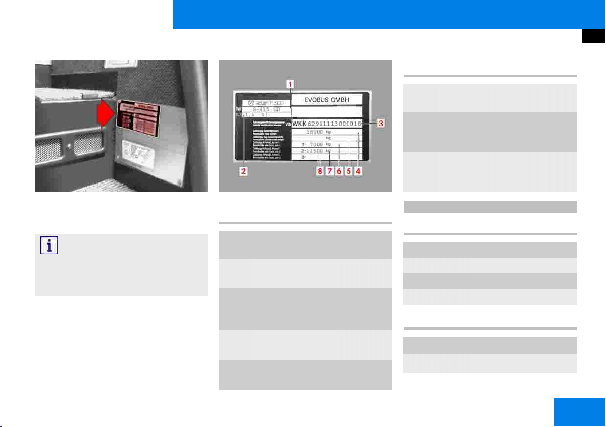
Vehicle identification
No. Designation Value
M00_00-0083-01
The identification plate is located at the
front entrance on the right
Note:
It is very important to identify the vehicle
exactly so that the correct “vehicle data”
can be assigned.
M00_00-0155-01
No. Designation Value
1
Vehicle designation
2
Headlamp basic
setting
3
Vehicle identification number
(VIN)
4
Permissible gross
vehicle weight
5
Permissible gross
towing weight
6
Permissible axle
load for front axle
7
Permissible axle
load for driven
axle
8
Permissible axle
load for trailing
axle
S 415 HD
415 Vehicle length
411 10.16 m
415 12.20 m or 12.30 m
416 13.19 m
417 14.05 m
HD Vehicle height
HD
HDH
High decker
High decker, high
S 411/415 HD, S 415 HDC, S 415/416/417 HDH/04.2012 GB
1
Page 19

Vehicle identification
M00_00-0552-71
Vehicle identification number (1) is also
marked on the skeleton at the front of
the bus. It can be accessed via the
spare wheel cover (to open, use the
lever in the front right doorway).
2
S 411/415 HD, S 415 HDC, S 415/416/417 HDH/04.2012 GB
Page 20

Safety
Table of contents
The use of symbols and their meanings . . . . . . . . . . . . . . . . . . . . . . . . . . . . . . . . . . . . . . . . . . . . . . . . . . . . . . . . . 4
Notes on vehicle safety . . . . . . . . . . . . . . . . . . . . . . . . . . . . . . . . . . . . . . . . . . . . . . . . . . . . . . . . . . . . . . . . . . . . . . 4
Operating safety . . . . . . . . . . . . . . . . . . . . . . . . . . . . . . . . . . . . . . . . . . . . . . . . . . . . . . . . . . . . . . . . . . . . . . . . . . . . 5
EU Directive 2001/85 . . . . . . . . . . . . . . . . . . . . . . . . . . . . . . . . . . . . . . . . . . . . . . . . . . . . . . . . . . . . . . . . . . . . . . . . 5
Stickers . . . . . . . . . . . . . . . . . . . . . . . . . . . . . . . . . . . . . . . . . . . . . . . . . . . . . . . . . . . . . . . . . . . . . . . . . . . . . . . . . . . . 6
Navigation and global positioning system . . . . . . . . . . . . . . . . . . . . . . . . . . . . . . . . . . . . . . . . . . . . . . . . . . . . . . . 6
Operation of the radio and mobile communications equipment . . . . . . . . . . . . . . . . . . . . . . . . . . . . . . . . . . . . . 7
Operation of mobile phones and radio equipment without an exterior aerial . . . . . . . . . . . . . . . . . . . . . . . . . . 7
Washing the outside of the bus in an automatic vehicle wash . . . . . . . . . . . . . . . . . . . . . . . . . . . . . . . . . . . . . . 8
Storage space for hand luggage . . . . . . . . . . . . . . . . . . . . . . . . . . . . . . . . . . . . . . . . . . . . . . . . . . . . . . . . . . . . . . . 9
Driver's rest area safety precautions . . . . . . . . . . . . . . . . . . . . . . . . . . . . . . . . . . . . . . . . . . . . . . . . . . . . . . . . . . . 9
Windscreen wiper system safety precautions . . . . . . . . . . . . . . . . . . . . . . . . . . . . . . . . . . . . . . . . . . . . . . . . . . . . 9
Safety precautions for the air-conditioning system . . . . . . . . . . . . . . . . . . . . . . . . . . . . . . . . . . . . . . . . . . . . . . . 10
Operation of auxiliary heating . . . . . . . . . . . . . . . . . . . . . . . . . . . . . . . . . . . . . . . . . . . . . . . . . . . . . . . . . . . . . . . . 10
S 411/415 HD, S 415 HDC, S 415/416/417 HDH/04.2012 GB
3
Page 21
Safety
The use of symbols and their meanings
The use of symbols and their
meanings
Safety precautions and other important
instructions are highlighted by symbols.
In addition to the instructions listed in
the contents, the safety and accident
prevention regulations issued by German
Employer's Liability Insurance Associations must be observed.
Instructions and information printed on
the packaging for components, tools and
service products must also be observed.
Where information and instructions are
to be observed, it is also assumed that
the user information is intended for persons who are suitably qualified to carry
out the tasks by nature of their education, training and experience.
At the same time, these persons should
be able to identify risks that may arise in
the undertaking of their tasks and take
the necessary measures to avoid them.
Meaning of symbols:
Note:
Notes about important additional information
Caution:
Warning notes about damage that may
occur in the event of non-compliance
Danger.
Warning notes for risks to persons
Environmental protection
Notes about environmental protection
measures
Reference to more detailed and addi-
tional user information
Notes on vehicle safety
We recommend that you:
Use only genuine parts that are
OMNIplus quality tested and conversion parts and accessories that
have been expressly approved by
EvoBus for the bus model concerned
in order to rule out the possibility
of jeopardising road safety and
invalidating the warranty and general
operating permit. These parts have
been specially tested for their safety,
reliability and suitability.
You can obtain further information from
any EvoBus Service Partner.
4
S 411/415 HD, S 415 HDC, S 415/416/417 HDH/04.2012 GB
Page 22

Safety
Operating safety
Operating safety
Important notes:
Any work or modifications that have
been carried out incorrectly on the
bus may result in malfunctions.
Tampering with electronic components and their software may cause
malfunctions. As electronic components are networked, these malfunctions may also cause other, indirectly related systems to malfunction.
These malfunctions may jeopardise
the operating safety and reliability of
the bus.
Retrofitted electrical or electronic
devices must possess type-approval
complying with Directive 95/54/EC
or ECE Directive 10/02.
Materials that are fitted in the bus
during the course of installation, conversion or modification work and
that are subject to mandatory firetesting requirements must also satisfy the conditions of EU Directive
95/28/EC.
Materials and components in
seats and seat fixtures that are
also fitted in the bus during the
course of installation, conversion or
modification must also satisfy the
following directives: 76/115/EEC
as amended by 96/38/EC, 74/
408/EEC as amended by 96/
37/EC, 77/541/EEC as amended by
96/36/EC
When such materials and components are purchased or installed, care
shall be taken to ensure that they
are appropriately certified. Use of
materials and components that do
not possess the certificate referred
to above can result in the operating
permit being invalidated.
We recommend that you have any
work or modifications carried out by
an EvoBus Service Partner.
EU Directive 2001/85
Registration as class 1: city public
service bus
Vehicles constructed with areas for
standing passengers, to allow frequent passenger movement
Registration as class 2: long-distance
public service bus
Principally for the carriage of seated
passengers. Designed to allow the
carriage of standing passengers in
the gangway and/or in an area which
does not exceed the space provided
for two double seats.
Registration as class 3: tourist coach
Exclusively for the carriage of seated
passengers.
Important information for buses
classified in accordance with EU
Directive 2001/85 into class 2 and 3
(mixed approval):
The operator of the bus is responsible for ensuring that the bus is restored to the condition consistent
S 411/415 HD, S 415 HDC, S 415/416/417 HDH/04.2012 GB
5
Page 23
Safety
Stickers
with the permissible type of operation of the class concerned.
For instance, this means that, in the
case of a bus being used in accordance with class 2, it is necessary to
ensure that the bus is operated with
seating having no aisle-side sideways
adjustment.
Stickers
There are various warning stickers affixed to your bus. These are intended to
make you and others aware of various
dangers. Therefore, do not remove any
warning stickers unless it is expressly
stated on the sticker that you may do
so.
Danger.
If you remove warning stickers, this could
result in you or other persons failing to
recognise dangers. You or others could
be injured as a result.
Navigation and global positioning system
Please follow the instructions below if
your bus is fitted with a navigation system:
Danger.
Please devote your attention primarily to
road and traffic conditions. Do not operate the navigation and positioning system unless the bus is stationary. Please
remember that your bus covers 14 m
every second when it is only travelling
at approximately 30 mph (50 km/h).
The navigation system is unable to detect the maximum load-bearing capacity
for bridges or the maximum permissible
height for driving through underpasses.
The driver is responsible for ensuring that
bridge load-bearing capacities and maximum headroom clearance are not exceeded.
6
S 411/415 HD, S 415 HDC, S 415/416/417 HDH/04.2012 GB
Page 24
Safety
Operation of the radio and mobile communications equipment
Operation of the radio and mobile
communications equipment
(e.g. telephone, radio, fax machine, etc.)
Danger.
Please devote your attention primarily
to road and traffic conditions. Do not
operate the display unit, radio or mobile
communications equipment unless the
traffic situation permits this to be done
safely. Please remember that your bus
covers 14 m every second when it is only
travelling at approximately 30 mph (50
km/h).
Note:
In the Federal Republic of Germany, Section 23, Paragraph 1a of the German road
traffic regulations (StVO) prohibit a vehicle
driver from using a mobile phone or an
on-board telephone/intercom if this use
involves lifting up or holding the mobile
phone or the telephone/intercom handset.
Danger.
Please observe local legal requirements
governing the use of mobile phones or
on-board telephones/intercoms in force in
the country of vehicle operation.
Operation of mobile phones and radio equipment without an exterior aerial
We advise against making or receiving
telephone calls in buses not equipped
with an exterior aerial as the operation
of radio transmitters, which include but
are not limited to radio telephones (mobile phones), may cause inadequately
shielded equipment (cardiac pacemakers
included) to malfunction.
Note:
If a mobile phone, radio system or fax
machine is retrofitted in the bus in a
manner that does not comply with EvoBus
installation specifications, the operating
permit for the bus could be invalidated
(EU Directive 95/54/EC).
S 411/415 HD, S 415 HDC, S 415/416/417 HDH/04.2012 GB
7
Page 25
Safety
Washing the outside of the bus in an automatic vehicle wash
Note:
Older peripherals (e.g. ticket-printing machines, ticket-cancelling machines, destination displays, etc.) that are still used in
new buses must comply with the technical requirements of EC Directive 72/245
EEC.
Danger.
Please observe local legal requirements
governing the use of mobile phones or
on-board telephones/intercoms in force in
the country of vehicle operation.
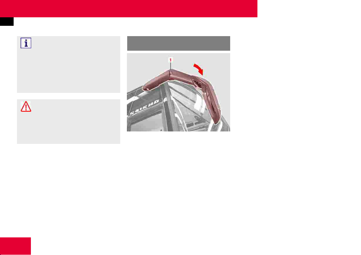
Washing the outside of the bus in
an automatic vehicle wash
M88_00-0013-01
Prior to washing the bus you must check
that the roof hatches, driver's window
and the doors are closed.
Set the heating/ventilation/air-conditioning system to air-recirculation mode
(Smog button).
The windscreen wiper must be set to
speed 0, otherwise the rain sensor could
be activated and trigger undesired wiping. This could result in damage to the
vehicle.
Before you wash the bus, fold both integral mirrors inwards towards the windscreen either manually by means of pivot
joint (1) on the mirror arm or, with electric mirrors, using the mirror adjustment
button on the instrument panel (option).
Remove any attachment parts that may
be fitted (e.g. satellite receiver on the
roof) prior to washing.
After the bus has been washed, you
must fold the integral mirrors outwards
again (manually or electrically, depending
on vehicle equipment).
8
S 411/415 HD, S 415 HDC, S 415/416/417 HDH/04.2012 GB
Page 26
Safety
Storage space for hand luggage
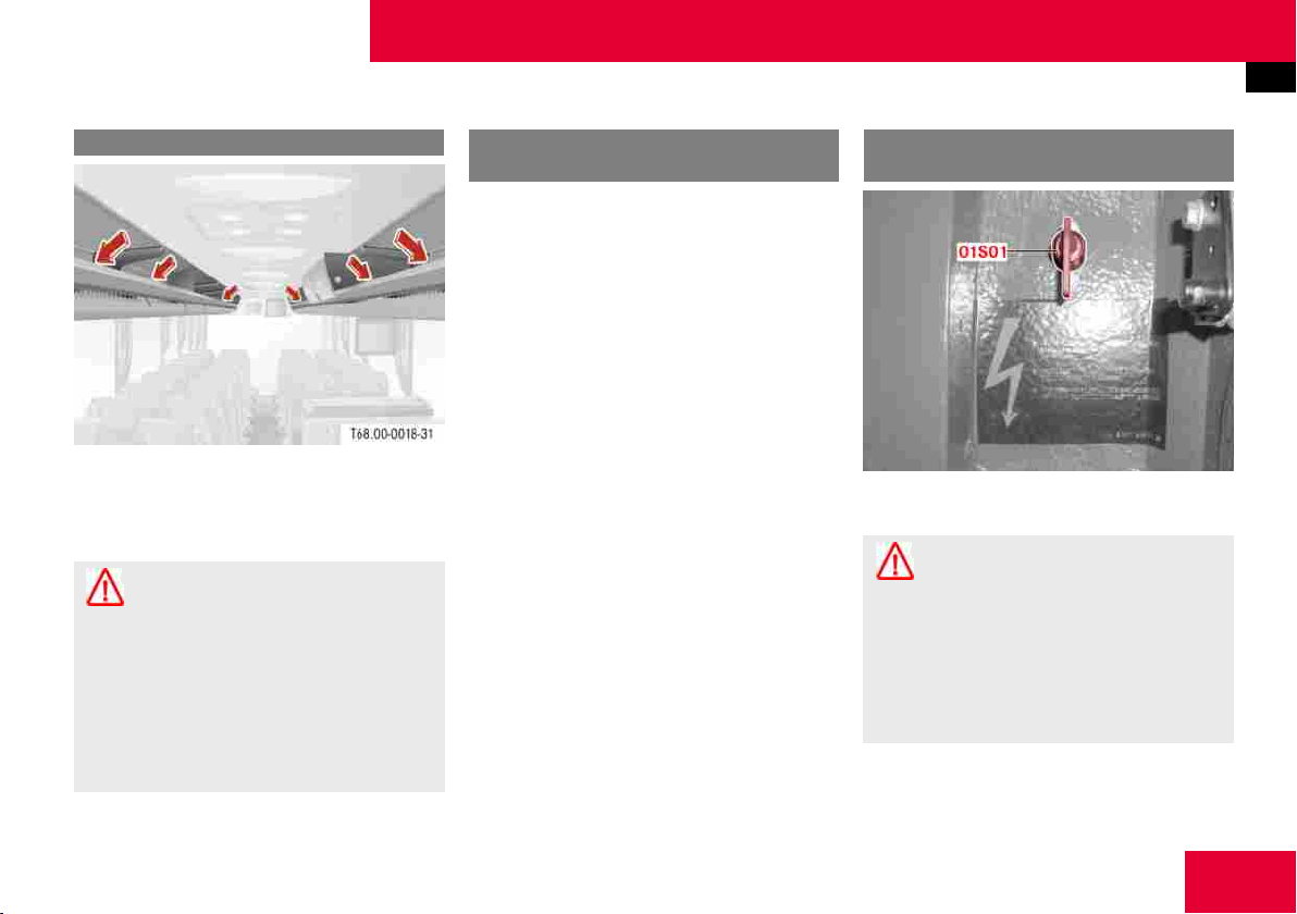
Storage space for hand luggage
T68_00-0018-31
The storage spaces above the passenger
seats are suitable for light hand luggage
items only.
Danger.
Occupants may be injured if the bus is
braked sharply, changes direction suddenly or is involved in an accident due
to objects being thrown around the bus.
Heavy or hard objects should therefore
not be carried inside the bus without being secured.
Driver's rest area safety precautions
The driver's rest area must only be used
by the bus driver (second driver).
The on-board telephone may only be
used by the driver in accordance with
legal requirements. Observe the legal
requirements of the country concerned.
Windscreen wiper system safety precautions
M54_00-1058-71
Danger.
RISK OF INJURY. The battery isolating
switch 01S01 must always be switched
off before any work is carried out on the
windscreen wiper system (wiper blade
cleaning, replacement of wiper blades or
wiper motor etc.).
S 411/415 HD, S 415 HDC, S 415/416/417 HDH/04.2012 GB
9
Page 27
Safety
Safety precautions for the air-conditioning system
Safety precautions for the airconditioning system
Air-conditioning systems that are operated with refrigerant R 134 a are labelled with appropriate stickers and/or
plates on the compressor.
Never mix R 134 a refrigerant and the
corresponding Triton SE 55 refrigerator
oil with other products.
In accordance with current good engineering practices, it is prohibited to allow
refrigerant to escape into the environment when operating, servicing or decommissioning air-conditioning systems.
Refrigerants and refrigerator oils must
be disposed of or recycled separately by
type and nature.
Only persons having the relevant and
necessary specialist knowledge, technical equipment and official approval (by
health and safety inspectorate, local authority, TÜV or equivalent) are permitted
to carry out maintenance work on airconditioning systems and take back refrigerants and oils.
The operator must maintain a logbook
auditing the consumption of refrigerant
and refrigerator oils.
Danger.
In automatically controlled air-conditioning
systems, the ventilation blowers of condenser or evaporator units may start up
at any time. Therefore, always switch
the ignition starter switch to OFF before any cleaning work is carried out.
Do not reach into the fan blades or fan
rollers. Avoid any contact with refrigerant as there is a risk of frostbite. Treat
affected skin areas as for frostbite, and
seek medical attention immediately. Carry
out maintenance and repair tasks with the
engine switched off whenever possible.
Keep a safe distance from moving parts
(e.g. belt drive) when the engine is running.
Operation of auxiliary heating
Danger.
Risk of fire and burns. There is a risk of
fires and burns due to the high exhaust
temperatures and the hot exhaust pipe
for the auxiliary heating. For this reason,
do not stop or park the bus over ignitable
materials (e.g. grass) when the auxiliary
heating is in operation, has recently been
in operation or has been operated by the
immediate heating button/preset clock.
Danger.
Risk of poisoning and suffocation. The
auxiliary heating must not be used in enclosed spaces such as garages or workshops due to the risk of poisoning and
suffocation. It must also not be used in
timer or preselection mode.
10
S 411/415 HD, S 415 HDC, S 415/416/417 HDH/04.2012 GB
Page 28

Danger.
Risk of explosion. The auxiliary heating
must be switched off at filling stations
and fuel dispensing systems due to the
risk of explosion.
Danger.
Risk of fire. The auxiliary heating must
remain switched off in places where ignitable vapours or dust can accumulate (e.g.
in the vicinity of filling stations, fuel, coal,
sawdust and grain stores or similar).
Safety
Operation of auxiliary heating
S 411/415 HD, S 415 HDC, S 415/416/417 HDH/04.2012 GB
11
Page 29

12
S 411/415 HD, S 415 HDC, S 415/416/417 HDH/04.2012 GB
Page 30

General
Table of contents
Preparation for the journey - daily tasks . . . . . . . . . . . . . . . . . . . . . . . . . . . . . . . . . . . . . . . . . . . . . . . . . . . . . . . 14
Preparation for the journey - weekly tasks . . . . . . . . . . . . . . . . . . . . . . . . . . . . . . . . . . . . . . . . . . . . . . . . . . . . . . 15
Preparation for the journey - monthly tasks . . . . . . . . . . . . . . . . . . . . . . . . . . . . . . . . . . . . . . . . . . . . . . . . . . . . . 16
Additional maintenance tasks dependent on bus use . . . . . . . . . . . . . . . . . . . . . . . . . . . . . . . . . . . . . . . . . . . . . 16
General bus care and maintenance . . . . . . . . . . . . . . . . . . . . . . . . . . . . . . . . . . . . . . . . . . . . . . . . . . . . . . . . . . . . 16
Care and cleaning . . . . . . . . . . . . . . . . . . . . . . . . . . . . . . . . . . . . . . . . . . . . . . . . . . . . . . . . . . . . . . . . . . . . . . . . . . 17
S 411/415 HD, S 415 HDC, S 415/416/417 HDH/04.2012 GB
13
Page 31

General
Preparation for the journey - daily tasks
Preparation for the journey - daily
tasks
Check the windscreen washer fluid level and the operation of the
windscreen washer system and windscreen wipers.
Check the fuel supply for the bus
engine and water heater (option)
Danger.
Switch off the engine and auxiliary heating before refuelling.
Check the AdBlue additive reservoir
for the BlueTec exhaust gas cleaning
system
Check the electrical system, paying
particular attention to the headlamps,
turn signals, tail lamps, brake lamps
and licence plate lamps.
Note:
Under certain weather and operating conditions, moisture may form on the inside
of the headlamps and other lights when
the bus is stationary. This does not indicate a fault or defect. The ventilation
openings in the headlamps allow this
moisture to dry off automatically after
the bus has been driven for a short time.
Check that the luggage compartment
flaps and the service covers are securely locked
Check the emergency exits
Insert the tachograph recording disc
or the driver card.
Note:
The indicator lamp in the speedometer
lights up if no disc or driver card has
been inserted.
Check that the emergency equipment is accessible and complete, e.g.
first-aid kit, fire extinguisher, warning
triangle, emergency hammer for side
windows, jack.
Check the adjustment of the
rear-view mirrors, clean the mirrors,
check the mirror heating for correct
function.
Check tyre pressures and tyre condition (including the spare wheel).
Check that the wheel nuts are firmly
seated.
14
S 411/415 HD, S 415 HDC, S 415/416/417 HDH/04.2012 GB
Page 32

General
Preparation for the journey - weekly tasks
M40_00-0115-71
Check wheel hubs (1) on all wheels
for leaks inside and out (visual
check).
Note:
If the wheel hubs are leaking, there may
be grease or oil residue on the tyres
themselves or deposits on the parking
area on which the bus is standing. Consult an EvoBus Service Partner in the
event of a leak.
Preparation for the journey - weekly
tasks
Check the coolant level in the cooling system and top it up if necessary.
Check the corrosion inhibitor/antifreeze concentration each time the
coolant has been topped up and correct if necessary.
Note:
Observe the Specifications for Service
Products.
Check the oil level in the hydraulic
steering system and top it up if necessary.
Caution:
If the oil level is low, have the steering
system checked at an authorised specialist workshop.
Check the belt tension of all belt
drives.
Carry out a visual check to ensure
there are no leaks in the engine,
transmission, driven axle, steering
or the cooling and heating systems.
Check the seat belts (belt arrester).
Check the belt straps for damage
(visual check).
Drain the fuel prefilter in the engine
compartment.
Note:
Refer to the “Practical advice” section.
Check the acid level in the starter
batteries (only on buses with leadacid batteries).
Danger.
Observe the safety precautions in the
“Practical advice” section.
S 411/415 HD, S 415 HDC, S 415/416/417 HDH/04.2012 GB
15
Page 33

General
Preparation for the journey - monthly tasks
Preparation for the journey monthly tasks
Check the residual current device
for the 230 V socket (option) in the
lavatory.
Note:
Refer to the “Lavatory” section
Additional maintenance tasks dependent on bus use
The bus operator must plan further
maintenance tasks for the heating/
ventilation/air-conditioning system
(driver’s area and passenger compartment) in addition to those indicated in the Maintenance Record.
General bus care and maintenance
Carry out the work specified in the
Maintenance Record
Caution:
Regular maintenance of the chassis and
drive train is essential to maintaining
the operating safety and roadworthiness
of the bus. The time intervals and the
scope of work required are specified in
the Maintenance Record supplied with the
bus.
Caution:
It is strongly recommended that the specified maintenance intervals be observed.
Note:
Our terms and conditions of sale and
delivery do not permit us to recognise
claims made under the warranty if the
periodic service and maintenance tasks
have not been carried out at the specified
distances (odometer reading) or times.
Have confirmation of the completion of
16
S 411/415 HD, S 415 HDC, S 415/416/417 HDH/04.2012 GB
Page 34

General
Care and cleaning
the work specified in the Maintenance
Record recorded by an EvoBus Service
Partner.
Care and cleaning
You will find instructions for and notes
on cleaning and caring for your bus in
the “Operation” section.
S 411/415 HD, S 415 HDC, S 415/416/417 HDH/04.2012 GB
17
Page 35

18
S 411/415 HD, S 415 HDC, S 415/416/417 HDH/04.2012 GB
Page 36

Operation
Table of contents
Running-in guideline . . . . . . . . . . . . . . . . . . . . . . . . . . . . . . . . . . . . . . . . . . . . . . . . . . . . . . . . . . . . . . . . . . . . . . . . 22
Starting the engine . . . . . . . . . . . . . . . . . . . . . . . . . . . . . . . . . . . . . . . . . . . . . . . . . . . . . . . . . . . . . . . . . . . . . . . . . 22
Driving . . . . . . . . . . . . . . . . . . . . . . . . . . . . . . . . . . . . . . . . . . . . . . . . . . . . . . . . . . . . . . . . . . . . . . . . . . . . . . . . . . . 24
Stopping the engine . . . . . . . . . . . . . . . . . . . . . . . . . . . . . . . . . . . . . . . . . . . . . . . . . . . . . . . . . . . . . . . . . . . . . . . . 25
Towing and tow-starting . . . . . . . . . . . . . . . . . . . . . . . . . . . . . . . . . . . . . . . . . . . . . . . . . . . . . . . . . . . . . . . . . . . . . 26
Trailer towing . . . . . . . . . . . . . . . . . . . . . . . . . . . . . . . . . . . . . . . . . . . . . . . . . . . . . . . . . . . . . . . . . . . . . . . . . . . . . . 29
Loading a trailer . . . . . . . . . . . . . . . . . . . . . . . . . . . . . . . . . . . . . . . . . . . . . . . . . . . . . . . . . . . . . . . . . . . . . . . . . . . . 30
Driving with a trailer . . . . . . . . . . . . . . . . . . . . . . . . . . . . . . . . . . . . . . . . . . . . . . . . . . . . . . . . . . . . . . . . . . . . . . . . 30
Ball hitch trailer coupling (fixed) (option) . . . . . . . . . . . . . . . . . . . . . . . . . . . . . . . . . . . . . . . . . . . . . . . . . . . . . . . 31
Ball hitch trailer coupling and open-jaw trailer coupling (detachable) (option) . . . . . . . . . . . . . . . . . . . . . . . . 32
Connecting the power supply . . . . . . . . . . . . . . . . . . . . . . . . . . . . . . . . . . . . . . . . . . . . . . . . . . . . . . . . . . . . . . . . . 32
Trailer coupling maintenance . . . . . . . . . . . . . . . . . . . . . . . . . . . . . . . . . . . . . . . . . . . . . . . . . . . . . . . . . . . . . . . . . 33
Refuelling (diesel fuel) . . . . . . . . . . . . . . . . . . . . . . . . . . . . . . . . . . . . . . . . . . . . . . . . . . . . . . . . . . . . . . . . . . . . . . . 33
BlueTec exhaust gas cleaning system . . . . . . . . . . . . . . . . . . . . . . . . . . . . . . . . . . . . . . . . . . . . . . . . . . . . . . . . . . 35
AdBlue service product . . . . . . . . . . . . . . . . . . . . . . . . . . . . . . . . . . . . . . . . . . . . . . . . . . . . . . . . . . . . . . . . . . . . . . 37
Filling with AdBlue . . . . . . . . . . . . . . . . . . . . . . . . . . . . . . . . . . . . . . . . . . . . . . . . . . . . . . . . . . . . . . . . . . . . . . . . . . 39
S 411/415 HD, S 415 HDC, S 415/416/417 HDH/04.2012 GB
19
Page 37

Operation
Table of contents
Operating/malfunction displays: fuel system . . . . . . . . . . . . . . . . . . . . . . . . . . . . . . . . . . . . . . . . . . . . . . . . . . . 41
Function of the accident data recorder (ADR) (option) . . . . . . . . . . . . . . . . . . . . . . . . . . . . . . . . . . . . . . . . . . . . 44
Brake system safety precautions . . . . . . . . . . . . . . . . . . . . . . . . . . . . . . . . . . . . . . . . . . . . . . . . . . . . . . . . . . . . . 45
Emergency braking . . . . . . . . . . . . . . . . . . . . . . . . . . . . . . . . . . . . . . . . . . . . . . . . . . . . . . . . . . . . . . . . . . . . . . . . . 45
Braking and stopping . . . . . . . . . . . . . . . . . . . . . . . . . . . . . . . . . . . . . . . . . . . . . . . . . . . . . . . . . . . . . . . . . . . . . . . 46
Brakes with anti-locking protection . . . . . . . . . . . . . . . . . . . . . . . . . . . . . . . . . . . . . . . . . . . . . . . . . . . . . . . . . . . . 46
Applying the parking brake . . . . . . . . . . . . . . . . . . . . . . . . . . . . . . . . . . . . . . . . . . . . . . . . . . . . . . . . . . . . . . . . . . 47
Releasing the parking brake . . . . . . . . . . . . . . . . . . . . . . . . . . . . . . . . . . . . . . . . . . . . . . . . . . . . . . . . . . . . . . . . . . 48
Emergency braking in the event of failure of both brake circuits . . . . . . . . . . . . . . . . . . . . . . . . . . . . . . . . . . . 48
EBS brake system . . . . . . . . . . . . . . . . . . . . . . . . . . . . . . . . . . . . . . . . . . . . . . . . . . . . . . . . . . . . . . . . . . . . . . . . . . 49
Acceleration skid control (ASR) . . . . . . . . . . . . . . . . . . . . . . . . . . . . . . . . . . . . . . . . . . . . . . . . . . . . . . . . . . . . . . . 50
Brake Assist . . . . . . . . . . . . . . . . . . . . . . . . . . . . . . . . . . . . . . . . . . . . . . . . . . . . . . . . . . . . . . . . . . . . . . . . . . . . . . . 50
Adaptive brake lamps . . . . . . . . . . . . . . . . . . . . . . . . . . . . . . . . . . . . . . . . . . . . . . . . . . . . . . . . . . . . . . . . . . . . . . . 50
Electronic Stability Program (ESP) (system description) . . . . . . . . . . . . . . . . . . . . . . . . . . . . . . . . . . . . . . . . . . . 51
Electronic Stability Program (ESP) (function description) . . . . . . . . . . . . . . . . . . . . . . . . . . . . . . . . . . . . . . . . . . 52
Deactivating the Electronic Stability Program (ESP) . . . . . . . . . . . . . . . . . . . . . . . . . . . . . . . . . . . . . . . . . . . . . . 54
20
S 411/415 HD, S 415 HDC, S 415/416/417 HDH/04.2012 GB
Page 38

Operation
Table of contents
Operating/malfunction displays: brake system . . . . . . . . . . . . . . . . . . . . . . . . . . . . . . . . . . . . . . . . . . . . . . . . . . 54
Operating 230/400 V systems (option) . . . . . . . . . . . . . . . . . . . . . . . . . . . . . . . . . . . . . . . . . . . . . . . . . . . . . . . . 61
Fitting the skibox (option) . . . . . . . . . . . . . . . . . . . . . . . . . . . . . . . . . . . . . . . . . . . . . . . . . . . . . . . . . . . . . . . . . . . 62
Swivelling the skibox (option) . . . . . . . . . . . . . . . . . . . . . . . . . . . . . . . . . . . . . . . . . . . . . . . . . . . . . . . . . . . . . . . . 64
Further skibox (option) operating instructions . . . . . . . . . . . . . . . . . . . . . . . . . . . . . . . . . . . . . . . . . . . . . . . . . . . 65
Note on maintenance work . . . . . . . . . . . . . . . . . . . . . . . . . . . . . . . . . . . . . . . . . . . . . . . . . . . . . . . . . . . . . . . . . . 65
Cleaning the underbody . . . . . . . . . . . . . . . . . . . . . . . . . . . . . . . . . . . . . . . . . . . . . . . . . . . . . . . . . . . . . . . . . . . . . 66
Care and cleaning . . . . . . . . . . . . . . . . . . . . . . . . . . . . . . . . . . . . . . . . . . . . . . . . . . . . . . . . . . . . . . . . . . . . . . . . . . 70
Care/cleaning of light-alloy wheels . . . . . . . . . . . . . . . . . . . . . . . . . . . . . . . . . . . . . . . . . . . . . . . . . . . . . . . . . . . . 72
Care and cleaning of covers and upholstery . . . . . . . . . . . . . . . . . . . . . . . . . . . . . . . . . . . . . . . . . . . . . . . . . . . . 73
Care/cleaning of fabric covers . . . . . . . . . . . . . . . . . . . . . . . . . . . . . . . . . . . . . . . . . . . . . . . . . . . . . . . . . . . . . . . . 73
Care/cleaning of micro-fibre covers . . . . . . . . . . . . . . . . . . . . . . . . . . . . . . . . . . . . . . . . . . . . . . . . . . . . . . . . . . . 74
Care/cleaning of leather covers . . . . . . . . . . . . . . . . . . . . . . . . . . . . . . . . . . . . . . . . . . . . . . . . . . . . . . . . . . . . . . 76
S 411/415 HD, S 415 HDC, S 415/416/417 HDH/04.2012 GB
21
Page 39

Operation
Running-in guideline
Running-in guideline
Running in the chassis and drive train
Note:
The way in which the chassis and drive
train of the new bus are treated during
the first 3,000 miles (5,000 km) is critical to the bus' future performance and
service life.
Note:
The load to which the bus is subjected
during this period should be increased
only gradually. The maintenance and lubrication tasks specified in the Maintenance Record should be carried out conscientiously.
Caution:
Do not place the engine under full load
during the running-in period. Up to
1,200 miles (2,000 km): run in with
care. Drive at no higher than 3/4 of the
maximum rpm in each gear. After 1,200
miles (2,000 km): slowly increase to the
economic rpm in each gear. During the
running-in period, do not drive the bus for
long distances at the same road speed =
same rpm. Varying engine speeds and
therefore varying loads demanded of the
entire drive train are favourable to the
running-in of the bus.
Starting the engine
The parking brake must be applied.
Transmission in neutral.
Note:
Do not depress the clutch pedal while
starting the engine.
Note:
At outside temperatures of below -20 °C,
preheat the engine with the water heater
(refer to “Heating/ventilation/air-conditioning control panel”).
Note:
The bus is equipped with an immobiliser
as standard. The engine cannot be started without one of the authorised keys.
22
S 411/415 HD, S 415 HDC, S 415/416/417 HDH/04.2012 GB
Page 40

Operation
Starting the engine
M54_00-0083-01
Turn the ignition switch to position
2, the bus carries out an indicator
lamp check (all indicator lamps must
light up briefly), then turn the ignition switch to position 3 but do not
depress the accelerator pedal.
If necessary, cancel the starting
procedure after a maximum of 15
seconds and wait for about 1 minute
before repeating the starting procedure. Turn the key fully back before
making a further attempt to start the
engine.
Note:
After a maximum of 3 starting attempts,
wait (about 15 minutes) before trying
again.
If this icon appears on the display
screen in conjunction with a yellow
alert, you have made 5 starting attempts using an invalid key. The immobiliser has been activated.
Note:
Use a valid key or valid spare key.
Note:
Each further starting attempt with an invalid key increases the waiting period by
1 further minute.
Note:
For emergencies, we recommend that you
always carry a spare key to which you
have access at all times.
Release the key when the engine
starts.
Caution:
It is not permitted to increase the engine
speed while the “Oil pressure too low”
symbol is shown on the display screen.
If the “Oil pressure too low” symbol appears for more than 10 seconds, turn off
the engine immediately and establish the
cause.
Observe the screen display: if malfunction messages appear, determine
the cause and rectify it.
S 411/415 HD, S 415 HDC, S 415/416/417 HDH/04.2012 GB
23
Page 41

Operation
Driving
Danger.
If there is insufficient pressure in the
compressed-air supply system (supply
pressure operating displays remain on
the display screen), a warning signal
sounds until the required pressure has
been reached. Do not release the parking
brake until there is sufficient operating
pressure.
Driving
Note:
Under certain conditions, the driver may
feel a slight judder when stationary (3axle bus). This is due simply to a function
test of the steering system and should
not be regarded as a fault.
Environmental protection
Never warm up the engine by allowing it
to idle with the bus stationary. Instead,
drive off and operate the engine at moderate engine speeds.
Danger.
All doors must be unlocked before the
bus is driven off.
Danger.
The freedom of movement of the pedals must not be restricted. The operating safety and roadworthiness of the bus
would otherwise be at risk. Objects could
fall and get caught between the pedals if
you were to accelerate or brake suddenly,
with the result that you would no longer
be able to brake, depress the clutch pedal or accelerate. You could cause an accident and endanger yourself and others.
24
Note:
The engine should not be placed under
full load until it has reached normal operating temperature (75 °C - 90 °C depending on operating conditions and the
outside temperature).
S 411/415 HD, S 415 HDC, S 415/416/417 HDH/04.2012 GB
Check the freedom of movement of
the pedals
Page 42

Operation
Stopping the engine
Danger.
Where floormats and carpets are fitted,
make sure that these are safely secured
against slipping and that the pedals have
sufficient clearance.
Danger.
Do not stow any objects in the driver's
footwell.
Danger.
Stow and secure all loose objects in
such a way that they cannot get into
the driver's footwell when the bus is in
motion.
Always pull away in 1st gear at 600 800 rpm.
Danger.
Test the service brake immediately after
pulling away.
Keep an eye on the rev counter while
driving.
Note:
Keep within the economical operating
range. Make sure that the engine speed
does not enter the danger zone (red
zone).
Danger.
If a warning buzzer sounds during a gearshift, the gear that you have attempted to
engage is too low. In this event, be sure
to keep the clutch pedal depressed and
select a suitable gear for the current road
speed.
Stopping the engine
M54_00-0083-01
Stop the bus - Shift the transmission into neutral - Apply the parking
brake. Turn the ignition switch from
position 2 (drive position) back to
position 1.
S 411/415 HD, S 415 HDC, S 415/416/417 HDH/04.2012 GB
25
Page 43

Operation
Towing and tow-starting
Danger.
There is a risk of fire and burns due to
the high exhaust temperatures and the
hot exhaust pipe for the auxiliary heating.
For this reason, make sure when stopping
the bus that there is no ignitable material
(e.g. dry grass, leaves, etc.) in the area
around the exhaust system, the engine
and the auxiliary heating exhaust system.
Towing and tow-starting
Danger.
Only authorised specialists (recovery service) are permitted to tow away brokendown buses. The rules and regulations in
the country concerned must be observed.
Caution:
Special measures are required in order
to protect the transmission if the bus is
to be towed: for safety reasons the propeller shaft must always be removed. The
propeller shaft securing screws at the
axle flange must be removed and those
at the transmission flange secured against
displacement.
Note:
Before you switch off the engine, allow
it to continue running at idling speed for
approximately 1-2 minutes (to allow the
exhaust turbochargers to cool down if the
coolant temperature is high or if you have
been driving at full engine output (e.g. on
hilly roads)).
26
S 411/415 HD, S 415 HDC, S 415/416/417 HDH/04.2012 GB
Danger.
The ignition starter switch of the vehicle
being towed must always remain in position 1 during the towing procedure.
The steering lock must not be allowed
to engage. Failure to comply with this
guideline could result in the steering locking.
Danger.
In buses with the Electronic Stability Program (ESP), this function must be deactivated without exception - refer to the
“Operation” section.
For notes on safety and operation relating to the trailer coupling, refer to the
“Operation” section.
Page 44

Operation
Towing and tow-starting
Note:
For notes on charging the compressed-air
system of a bus to be towed, refer to the
“Practical advice” section.
Screw the towing coupling into locating bore (1).
M00_00-0152-01
Removing the front panel
Note:
Open the spare wheel flap by pulling the
lever in the front right doorway.
Note:
Front panel (2) that conceals the locating
bore for the towing jaws can be removed
by undoing the 4 securing screws (1).
M00_00-0358-71
Front/rear towing hitch:
Note:
To tow the bus, there are some towing
jaws in the vehicle tool kit that have to
be screwed into locating bore (1) provided
behind the front panel or in the rear
member.
S 411/415 HD, S 415 HDC, S 415/416/417 HDH/04.2012 GB
27
Page 45

Operation
Towing and tow-starting
M00_00-0340-71
Insert the rigid tow bar into towing
coupling (3) and secure with the
linchpin. Turn linchpin (1) towards
the rear until it engages in lock (2).
Note:
Linchpin (1) must always remain engaged
in lock (2) when the bus is being towed.
Removal of the rigid tow bar in reverse order
Note:
Pull lock (2) up slightly in order to disengage linchpin (1) towards the front.
Towing with the front axle
Danger.
The ignition starter switch must not be
switched to position 2 while the front axle
is raised. The wheels on the driven axle
may lock. Failure to comply could result
in brake intervention by the ABS/ASR
system, which could cause the rear axle
to skid.
Tow-starting (only for manual transmission)
Note:
The bus cannot be tow-started unless the
batteries are fully charged (at least 21 V).
Caution:
Always tow-start the bus with the batteries connected. Turn the ignition starter
switch to the drive position. Depress the
clutch pedal fully. Select 2nd or 3rd gear.
Have the towing vehicle pull away and
then release the clutch pedal and depress
the accelerator pedal until the engine
starts.
Caution:
Vehicles with automated manual transmission (option) cannot be tow-started.
28
S 411/415 HD, S 415 HDC, S 415/416/417 HDH/04.2012 GB
Page 46

Note:
Jump-starting - refer to the “Practical advice” section.
This warning must be observed if the
vehicle is to be towed.
Caution:
There is a risk of damage to the lefthand exterior mirror caused by the towing
vehicle as the bus is being towed through
tight left-hand bends. There is a risk of
damage to the bus caused by the tow bar
as the bus is being towed through tight
right-hand bends. Observe the information/instructions on the sticker on the
tow bar.
Trailer towing
Danger.
Proceed with utmost care and caution
when hitching up the trailer. Make sure
that no persons are present between the
trailer and vehicle as the vehicle is being reversed into engagement with the
trailer. The overrun brake of a trailer can
rebound uncontrollably when in overrun
mode. To reduce the risk of serious injuries, do not uncouple any trailer that has
an overrun brake if the trailer has overrun and the overrun brake is applied. A
trailer that has been coupled to the towing vehicle incorrectly could break away.
A correctly coupled trailer must stand horizontal behind the vehicle. Use a trailer
with a height-adjustable drawbar if necessary. The maximum permissible noseweight and rear axle load of the bus must
not be exceeded.
Operation
Trailer towing
Note:
Observe the operating instructions issued
by the trailer manufacturer.
Note:
If the trailer coupling is a detachable
coupling, the operating instructions issued by the trailer coupling manufacturer
must be observed.
Note:
Trailers having a maximum gross weight
of higher than 3.5 t require that appropriate body reinforcement measures be
implemented during vehicle manufacture.
In this case, ESP (Electronic Stability Program) would no longer be available (even
with no trailer coupled).
S 411/415 HD, S 415 HDC, S 415/416/417 HDH/04.2012 GB
29
Page 47

Operation
Loading a trailer
Note:
It is prohibited to a couple a turntable
trailer or any trailer equipped with ESP.
Loading a trailer
Observe the following values when
loading the trailer:
the permissible gross weight of the
trailer
the permissible trailer load of the
vehicle and the trailer tow hitch
the permissible noseweight
the permissible rear axle load of the
towing vehicle
the permissible gross weight of both
the towing vehicle and the trailer
The definitive maximum permissible values are listed in the vehicle documents
and on the identification plates of the
trailer tow hitch, trailer and vehicle. If
there are discrepancies between any of
these sources, always consider the lowest value to be valid.
Driving with a trailer
The following changes in handling
characteristics can be observed when
driving with a trailer attached:
acceleration and gradient-climbing
capability are reduced
braking distance is increased
sensitivity to crosswinds is increased
directional stability is adversely af-
fected
fuel consumption is increased
Avoid driving a vehicle/trailer combination faster than 80 km/h, even in countries where higher speeds are permitted.
Maintain a greater distance from the
vehicle in front than you would when
driving without a trailer.
Avoid sudden braking where possible.
Brake gently at first to allow the trailer to run on and quickly increase your
braking force.
30
S 411/415 HD, S 415 HDC, S 415/416/417 HDH/04.2012 GB
Page 48

Operation
Ball hitch trailer coupling (fixed) (option)
If the trailer begins to swing from side to
side:
release the accelerator pedal
do not countersteer
brake if necessary
do not attempt to draw the vehicle/
trailer combination out by accelerating
The gradient-climbing capabilities from a
standstill refer to sea level. When driving in mountainous areas, you should
bear in mind that the power output of
the engine and thus its gradient-climbing capability decrease with increasing
altitude.
On long and steep downhill gradients,
select a lower gear/shift range in good
time. This makes use of the braking effect of the engine, reducing the amount
of braking effort required to maintain a
safe speed. The load on the brake system is therefore reduced, which helps to
prevent the brakes from overheating and
wearing too rapidly. If additional braking effort is required, do not depress the
brake pedal with one continuous press,
but operate it at intervals.
Danger.
While the vehicle is in motion, never keep
the brake pedal continuously depressed,
e.g. avoid allowing the brakes to slip as a
consequence of you resting your foot on
the pedal. This causes the brake system
to overheat, increases the braking distance and may result in a complete loss
of braking effect.
Ball hitch trailer coupling (fixed)
(option)
Note:
Observe the operating instructions issued
by the trailer manufacturer.
Secure the trailer against rolling
away.
Reverse the vehicle until the towing
ball on the trailer drawbar is positioned precisely above the ball end
on the vehicle.
Hitch the trailer as described in the
operating instructions issued by the
trailer manufacturer.
S 411/415 HD, S 415 HDC, S 415/416/417 HDH/04.2012 GB
31
Page 49

Operation
Ball hitch trailer coupling and open-jaw trailer coupling (detachable) (option)
Ball hitch trailer coupling and openjaw trailer coupling (detachable)
(option)
Note:
Observe the operating instructions issued
by the trailer manufacturer.
Note:
Observe the operating instructions issued
by the trailer coupling manufacturer.
Secure the trailer against rolling
away.
The trailer coupling is fitted to the
mounting on the end cross member.
To gain access to the mounting, remove the cover from the bumper and
stow the cover inside the bus.
M00_00-0512-71
Installation: slide catch (2) backwards and hold in this position. Turn
cover (3) through approximately 30°
and remove. Fit the trailer coupling
in reverse order.
Note:
Removal in reverse order. The trailer
coupling must be removed whenever it
is not in use.
Connecting the power supply
Note:
Before connecting the cable, check that
the voltage of the consumers on the trailer is the same as the voltage of the consumers on the towing vehicle.
To gain access to the trailer socket,
remove the cover from the bumper
and stow the cover inside the bus.
Insert the trailer connector into the
socket on the bus.
Note:
Route the cable in such a way that it
yields to any movement without tension,
kinking or friction, including movements
associated with cornering.
Check that the lights on the trailer
are clean and working correctly.
32
S 411/415 HD, S 415 HDC, S 415/416/417 HDH/04.2012 GB
Page 50

Operation
Trailer coupling maintenance
Trailer coupling maintenance
Clean the trailer coupling and lubricate it with multipurpose grease.
Check the screws securing the trailer coupling to the end cross member
for firm seating. Look for the inspection paint.
Danger.
If the threadlocking paint is damaged,
the trailer coupling must be checked and
resecured by a Service Partner. It is prohibited to use trailer coupling until then.
Refuelling (diesel fuel)
The vehicle has a 2-tank system fitted to
the front of the front axle (S 415 HD) or
to the rear of the driven axle (S 411 HD)
or to the rear of the trailing axle (S 415/
416/417 HDH). The fuel tanks are interconnected through their bases by a
fuel line. The bus can be refuelled from
either side. If the fuel tanks on your bus
are interconnected, it is necessary to remove the fuel cap from each of the fuel
tanks.
Use only diesel fuels compliant with EN
590 (refer to the Specifications for Service Products). Engines with BlueTec
exhaust gas aftertreatment system must
be run only on fuels having a fuel sulphur content of less than 50 ppm. In
the cold season, use winter-grade diesel fuel (effective down to approximately
-20 °C). If outside temperatures fall even
further, the flow properties of the diesel fuel could deteriorate to an unusable
level due to paraffin separation. As a
preventive measure for this situation, it
is permissible to add a specific amount
of an approved flow improver proportionate to the outside temperature. Engine
output may be degraded in line with the
amount of additive. The amount of additive should therefore be kept as low as
possible under consideration of expected outside temperatures. Observe all
relevant safety regulations.
Flow improvers are fuel additives that
improve the flow characteristics of
the fuel. Do not add flow improvers
to winter diesel fuel rated as effective
down to -22 °C. Flow improvers could
have a negative impact on the cold flow
characteristics of this fuel. In the case
of summer diesel fuels or less coldresistant winter diesel fuels, add an
amount of flow improver appropriate
to the expected outside temperature.
Add the fuel additive to the diesel fuel
well before the flow characteristics of
the diesel fuel have been degraded as a
result of paraffin separation. The only
way to eliminate malfunctions that arise
as a direct result of paraffin separation
is to raise the temperature across the
entire fuel system.
S 411/415 HD, S 415 HDC, S 415/416/417 HDH/04.2012 GB
33
Page 51

Operation
Refuelling (diesel fuel)
Switch off the engine and auxiliary heating before refuelling. Park the bus on a
level surface.
Cleanliness is of utmost importance
when refuelling. Do not leave cotton
rags or cloths in the vicinity of the open
filler neck.
Danger.
Fuel is toxic and harmful to health. For
this reason, make sure that the fuel does
not come into contact with skin, eyes
or clothing, that you do not inhale fuel
vapours and that children are kept away
from the fuel.
Environmental protection
If handled improperly, fuels constitute a
hazard to health and the environment.
Fuels must not be allowed to enter the
sewerage system, surface water, groundwater or soil.
Danger.
Risk of injury and explosion. Fuel is
highly flammable. Fire, naked flames and
smoking are therefore prohibited when
fuel is being handled.
Danger.
Before refuelling, switch off the auxiliary
heating to prevent fuel vapours from igniting on the auxiliary heating exhaust
system.
34
S 411/415 HD, S 415 HDC, S 415/416/417 HDH/04.2012 GB
Danger.
If you or others have come into contact
with fuel: In case of contact with the
eyes, rinse them immediately and copiously with clean water and seek medical
attention. Clean affected areas of skin
immediately with soap and water. Immediately change out of clothing that has
come into contact with fuel. If fuel has
been swallowed, seek medical attention
immediately.
Caution:
Use only approved flow improvers (MB
sheet 137.1).
Caution:
Biodiesel (FAME) may be used as an alternative to diesel fuel only in buses that
have been approved for operation with
biodiesel (FAME) ex works (custom requirement/code) or as a result of a conversion measure.
Page 52

Operation
BlueTec exhaust gas cleaning system
Caution:
The biodiesel (FAME) used must comply
with EN 14214. The use of pure vegetable oils is not permitted.
BlueTec exhaust gas cleaning
system
M47_00-0055-71
The BlueTec exhaust gas cleaning system
essentially comprises a supply tank, a
catalytic converter and an AdBlue metering system. It is electronically monitored
and controlled. Pollutants in the exhaust
gas are converted into environmentally
friendly substances through a combination of the addition of AdBlue and the
effect of the catalytic converter in the
exhaust silencer.
The illustration shows filler neck (1) for
the AdBlue supply tank (next to the diesel tank).
Note:
AdBlue is consumed at a rate of approximately 5 % of the rate of diesel fuel consumption. It is recommended that the
AdBlue supply tank also be refilled at
every regular refuelling stop.
To function correctly, the BlueTec exhaust gas cleaning system requires the
addition of a reducing agent (AdBlue).
The addition of AdBlue does not form
part of the routine scope of bus maintenance – it is the responsibility of the
vehicle operators to ensure that the
AdBlue supply tank is regularly replenished. Filling and operating the bus with
AdBlue is mandatory for compliance with
emission regulations and is thus one of
the conditions for the road traffic approval of the bus. The road traffic approval of the bus will be invalidated if
the bus is operated without AdBlue. The
legal consequence would be that the bus
S 411/415 HD, S 415 HDC, S 415/416/417 HDH/04.2012 GB
35
Page 53

Operation
BlueTec exhaust gas cleaning system
would no longer be permitted to be operated on public roads. In some countries,
operation of the bus without AdBlue may
be considered to be a criminal offence
or a violation of administrative law punishable by fine. Support in the purchase
or operation of the bus, i.e. tax relief,
road tax, may also be invalidated retrospectively. This may be the case both
in the country in which the vehicle is registered and in other countries in which
the vehicle is operated.
Danger.
It is essential that work relevant to safety
or work on safety-related systems be carried out at a qualified specialist workshop.
Danger.
Always have maintenance work carried
out at a qualified specialist workshop
which has the necessary knowledge and
tools.
Note:
AdBlue freezes at a temperature of
approximately -11 °C. The bus is
equipped with an AdBlue preheating
system as standard. Winter operation is
thus ensured, even at temperatures below
-11 °C.
Environmental protection
AdBlue is biologically degradable. Unless
it is handled properly, however, AdBlue
constitutes an environmental hazard. Do
not allow AdBlue to enter the sewage system, surface water, ground water or soil
in significant volumes.
Danger. Risk of poisoning and
injury.
AdBlue® is not classified as a hazardous
substance by German regulations governing hazardous substances. Nevertheless,
certain points should be observed when
handling AdBlue®.
The AdBlue® line system and the system
components connected to it are pres-
surised while the engine is warm. There
is a risk of scalding from hot AdBlue®
spraying out if the line system is suddenly
opened. There is also the risk of skin irritation or damage to the eyes if AdBlue®
comes into contact with the skin or eyes.
Wear protective gloves
Wear protective clothing
Wear safety goggles
Work on the exhaust gas aftertreat-
ment system should not be commenced until approximately 4 minutes
have passed as individual lines continue to be flushed with compressed
air even after the engine has been
switched off.
Turn the ignition starter switch to the
OFF position and remove the key before work is carried out on the SCR
system.
Allow the AdBlue® line system to
cool down
Open line connections and system
component covers/caps slowly.
Capture any AdBlue® that escapes in
a suitable container and dispose of
36
S 411/415 HD, S 415 HDC, S 415/416/417 HDH/04.2012 GB
Page 54

Operation
AdBlue service product
it in an environmentally responsible
manner.
Do not pour AdBlue® into drinks containers.
Wipe up any spilled AdBlue®, especially as there is a risk of slipping.
AdBlue® collected in this way must
not be poured back into the AdBlue®
supply tank.
Rinse affected areas of skin copiously
with clean water.
Quickly change out of clothing that
has come into contact with the substance.
In case of contact with the eyes,
rinse them immediately and copiously
with clean water and seek medical
attention if necessary.
If AdBlue® enters the mouth or is
swallowed, rinse the mouth out with
clean water and then drink plenty of
water.
Seek medical attention if symptoms
persist.
AdBlue service product
AdBlue is a non-flammable, colourless,
odourless water-soluble liquid.
Caution:
Use only AdBlue compliant with DIN 70
070. Special additives are not permitted.
Caution:
If, during refilling, AdBlue is spilled on
painted surfaces or aluminium surfaces,
rinse down the surfaces concerned
without delay.
AdBlue and high temperatures
Note:
Ammonia vapours may be released as a
product of the decomposition of AdBlue if
the content of the AdBlue tank is heated
to over 50 °C for a lengthy period (e.g.
as a consequence of direct sunlight).
Note:
Ammonia vapours have an acrid odour.
For this reason, you should avoid inhaling
any ammonia vapours that may escape
when you remove the AdBlue filler cap.
Ammonia vapours are neither toxic nor
hazardous to health in this concentration.
AdBlue and low temperatures
Note:
AdBlue freezes at a temperature of
approximately -11 °C. The bus is
equipped with an AdBlue preheating
system as standard. Winter operation is
thus ensured, even at temperatures below
-11 °C.
AdBlue additives
S 411/415 HD, S 415 HDC, S 415/416/417 HDH/04.2012 GB
37
Page 55

Operation
AdBlue service product
Caution:
Do not add any additives to AdBlue. Do
not dilute AdBlue with tap water. This
can destroy the exhaust gas cleaning system. Damage to the exhaust gas cleaning
system caused by additives/tap water will
invalidate the warranty.
Storage
Caution:
Use only containers made from high-alloy
CrNi steels or MoCrNi steels complying
with EN10088-1/2/3 for the storage of
AdBlue. Containers made of aluminium,
copper, alloys containing copper and nonalloy or galvanised steels are not suitable
for the storage of AdBlue. If stored in
such containers, AdBlue could dissolve
out constituents of these metals and destroy the exhaust gas cleaning system.
The vehicle warranty will be invalidated
if damage to the exhaust gas cleaning
system is found to have been caused
by constituents dissolved out of non-approved storage containers.
Disposal of AdBlue
Note:
Observe country-specific legislation and
requirements governing the disposal of
AdBlue.
AdBlue purity
Note:
It is not permitted to return to the tank
any AdBlue that has been pumped out,
e.g. during a repair, because the purity of
the liquid would no longer be guaranteed.
Service life and shelf life
Note:
In storage, AdBlue may decompose into
ammonium hydroxide and carbon dioxide.
In this event, it would no longer meet the
requirements of the DIN V 70070 standard. If AdBlue is stored at the recommended storage temperature of 25 °C, it will
continue to meet the requirements of this
standard for at least 6 months from the
date of manufacture. If the recommen-
ded storage temperature is exceeded, this
period will become shorter. At temperatures below -11 °C AdBlue will freeze and
solidify.
38
S 411/415 HD, S 415 HDC, S 415/416/417 HDH/04.2012 GB
Page 56

Filling with AdBlue
Note:
An accidental filling of the AdBlue supply tank with diesel fuel and vice versa is
prevented by various technical precautionary measures.
Note:
AdBlue is consumed at a rate of approximately 5 % of the rate of diesel fuel consumption. It is recommended that the
AdBlue supply tank also be refilled at
every regular refuelling stop.
Caution:
Use only AdBlue compliant with DIN 70
070. Special additives are not permitted.
Caution:
If, during refilling, AdBlue is spilled on
painted surfaces or aluminium surfaces,
rinse down the surfaces concerned
without delay.
Note:
AdBlue freezes at a temperature of
approximately -11 °C. The bus is
equipped with an AdBlue preheating
system as standard. Winter operation is
thus ensured, even at temperatures below
-11 °C.
Operation
Filling with AdBlue
M54_00-1372-71
Read AdBlue fill level (2).
S 411/415 HD, S 415 HDC, S 415/416/417 HDH/04.2012 GB
39
Page 57

Operation
Filling with AdBlue
M47_00-0091-71
If the fill level in the AdBlue supply
tank falls to approximately 10 %, a
yellow alert (1) appears on the display screen. The yellow alert displays “AdBlue” icon (1.1) and the
message “AdBlue Vorrat zu gering” (AdBlue level too low) (1.2).
The driver can acknowledge yellow alert (1) at any time using main
menu buttons (1.3) on the steering
wheel. AdBlue indicator (2) turns yellow and remains lit to remind the
driver that an AdBlue top-up is due.
Yellow warning lamp (3) does not go
out until the vehicle has been refilled
with AdBlue.
M47_00-0097-71
If the AdBlue supply tank runs empty,
a yellow alert (1) appears on the display screen. The yellow alert displays icon (1.1) and the message
“Motor Störung” (Engine malfunction) (1.2). In this situation, a fault
is also present in the exhaust gas
cleaning system, i.e. malfunction
indicator lamp (2) flashes. In this
event, it is necessary to fill up with
AdBlue immediately.
Note:
The driver must have actively acknowledged the “AdBlue Vorrat zu gering”
(AdBlue level too low) yellow alert (see
above) at some time previously.
M47_00-0096-71
If the AdBlue supply tank runs empty,
a 60 % engine power reduction is initiated and yellow alert (1) appears on
the display screen. Yellow alert (1)
displays icon (1.1) and the message
“Motor Leistungsreduzierung” (Engine
power reduction) (1.2). The driver
can acknowledge yellow alert (1)
40
S 411/415 HD, S 415 HDC, S 415/416/417 HDH/04.2012 GB
Page 58

Operation
Operating/malfunction displays: fuel system
at any time using main menu buttons (1.3) on the steering wheel.
M47_00-0055-71
Filling the tank with AdBlue.
Note:
On 2-axle buses, the AdBlue supply tank
is located directly next to the diesel fuel
tank. On 3-axle buses, the AdBlue supply
tank can be found behind the flap on the
right-hand side above the driven axle.
Note:
An accidental filling of the AdBlue supply tank with diesel fuel and vice versa is
prevented by various technical precautionary measures.
Operating/malfunction displays:
fuel system
Fuel reserve
M47_00-0092-71
If the fuel level drops below approximately 10 % of tank capacity, a yellow
alert (1) appears on the display screen.
The yellow alert displays icon (1.1) and
the message “Kraftstoffvorrat zu gering” (Fuel level too low) (1.2). The driver
can acknowledge yellow alert (1) at any
time using main menu buttons (1.3) on
the steering wheel. Fuel indicator (2)
turns yellow and remains lit to remind
the driver that the vehicle needs to be
S 411/415 HD, S 415 HDC, S 415/416/417 HDH/04.2012 GB
41
Page 59

Operation
Operating/malfunction displays: fuel system
refuelled. Yellow warning lamp (3) does
not go out until the vehicle has been refuelled.
AdBlue level
M47_00-0091-71
If the fill level in the AdBlue supply tank
falls to approximately 10 %, a yellow
alert (1) appears on the display screen.
The yellow alert displays “AdBlue”
icon (1.1) and the message “AdBlue
Vorrat zu gering” (AdBlue level too
low) (1.2). The driver can acknowledge
yellow alert (1) at any time using main
menu buttons (1.3) on the steering
wheel. AdBlue indicator (2) turns yellow
and remains lit to remind the driver
that an AdBlue top-up is due. Yellow
warning lamp (3) does not go out until
the vehicle has been refilled with AdBlue.
Exhaust gas cleaning malfunction
M47_00-0093-71
Malfunction indicator lamp (1) lights up
in the event of a malfunction in the exhaust gas cleaning system (SCR system).
Danger.
Have the malfunction rectified by an
EvoBus Service Partner immediately.
Fault in the exhaust gas cleaning
system
M47_00-0097-71
In the event of a fault in the exhaust
gas cleaning system (display indicating permissible NOx concentration exceeded slightly) or if the AdBlue supply tank runs dry, malfunction indicator lamp (2) flashes and yellow alert (1)
appears on the display screen. Yel-
42
S 411/415 HD, S 415 HDC, S 415/416/417 HDH/04.2012 GB
Page 60

Operation
Operating/malfunction displays: fuel system
low alert (1) displays icon (1.1) and the
message “Motor Störung” (Engine malfunction) (1.2). The driver can acknowledge yellow alert (1) at any time using
main menu buttons (1.3) on the steering
wheel. If the malfunction message was
triggered by AdBlue supply tank (3) running empty, it is necessary to top up the
AdBlue level immediately. If the AdBlue
supply tank has run empty, the driver
must have actively acknowledged the
“AdBlue Vorrat zu gering” (AdBlue level
too low) yellow alert (see above) at some
time previously.
Danger.
Have NOx faults rectified immediately by
an EvoBus Service Partner.
Note:
If the AdBlue supply tank runs empty,
engine power is automatically reduced to
approximately 60 %.
Engine power reduction
M47_00-0096-71
In the event of an NOx fault (display indicating NOx concentration exceeded
significantly) or if the AdBlue supply tank
runs empty, engine power is automatically reduced to approximately 60 %
and yellow alert (1) appears on the display screen. The yellow alert displays
icon (1.1) and the message “Motor Leistungsreduzierung” (Engine power reduction) (1.2). The driver can acknowledge yellow alert (1) at any time using
main menu buttons (1.3) on the steering wheel. The driver must have actively
acknowledged the “Motor Störung” (Engine malfunction) yellow alert beforehand
(see above). In this situation, a fault is
also present in the exhaust gas cleaning system, i.e. malfunction indicator
lamp (2) flashes. If the fault was caused
by AdBlue supply tank (3) running empty,
the driver has manually acknowledged
the “AdBlue Vorrat zu gering” (AdBlue
level too low) yellow alert (see above) at
some time previously. The AdBlue supply
tank must be filled immediately.
Danger.
Have NOx faults rectified immediately by
an EvoBus Service Partner.
S 411/415 HD, S 415 HDC, S 415/416/417 HDH/04.2012 GB
43
Page 61

Operation
Function of the accident data recorder (ADR) (option)
Function of the accident data
recorder (ADR) (option)
The accident data recorder (ADR) is
a system for detecting and recording accidents and driving events, e.g.
pulling away against a kerb or sudden braking.
The accident data recorder (ADR)
is activated automatically when the
ignition is switched on.
M54_00-1502-71
Note:
The accident data recorder (ADR) remains
active for 3 days after the ignition has
been switched off and continues to register all vehicle movements (e.g. parking
collisions).
As soon as the ignition is switched
on, the accident data recorder (ADR)
carries out a self-test and provides
audible notification of the current
operating status or the presence of a
hardware fault.
Note:
A brief, one-off audible signal (buzzer in
the control panel) (4) indicates that the
accident data recorder (ADR) is ready for
operation.
Note:
Indicator lamp (2) lighting up and a brief,
one-off buzzing sound means that at least
one event is stored.
Note:
A sequence of four long buzzes indicates
that the accident data recorder (ADR) has
detected a parking collision. Check your
vehicle for damage.
Note:
Eight short buzzes mean that the memory
of the accident data recorder (ADR) is
almost full to capacity. Export the events
and have the memory cleared.
Note:
Ten short buzzes mean that the accident
data recorder (ADR) has malfunctioned.
Similarly, a malfunction is present if no
signal sounds.
44
S 411/415 HD, S 415 HDC, S 415/416/417 HDH/04.2012 GB
Page 62

Operation
Brake system safety precautions
Following any critical traffic or accident situation, it is possible to record
an entry manually.
Note:
When pushbutton (1) is pressed following an accident, the event (approximately
43 seconds before, during and after the
accident) is stored and remains write-protected for an extended period.
Brake system safety precautions
Caution:
The braking characteristics of the bus
may change if a yellow warning level
malfunction in the brake system is displayed on the screen in the instrument
cluster. Drive with extreme care. Have
the fault rectified as soon as possible by
an EvoBus Service Partner.
Danger.
The braking characteristics of the bus
have changed if a red warning level malfunction in the brake system is displayed.
Pedal travel may increase under braking.
ABS is switched off. Stop the bus immediately and disable it (traffic conditions
permitting). Have an EvoBus Service Partner rectify the fault immediately.
Emergency braking
In the event of danger, depress the
brake pedal fully.
Note:
If you brake heavily at a speed of over
30 mph (50 km/h) and Brake Assist is
active, the brake lamps will flash rapidly.
This provides a warning to road users
behind the vehicle.
S 411/415 HD, S 415 HDC, S 415/416/417 HDH/04.2012 GB
45
Page 63

Operation
Braking and stopping
Braking and stopping
When the bus is driven over long
downhill stretches, you should make
use of the braking effect of the engine by shifting into a lower gear.
Use the continuous brakes (retarder,
engine brake) to relieve the load on
the service brake.
Note:
Except for emergencies, the service brake
does not usually need to be applied
sharply.
Note:
Always apply the parking brake before
you disembark. On uphill and downhill
gradients, you must also chock the
wheels and turn the steering towards the
kerb.
Brakes with anti-locking protection
In the event of danger, the brake
pedal should be fully depressed. This
guarantees that all wheels are regulated and the bus decelerates optimally.
On a slippery road surface, you
should also declutch so that the
braking effect of the engine cannot
affect the ABS control intervention.
Note:
The retarder is automatically deactivated
for the duration of an ABS control intervention.
Danger.
The anti-locking protection of ABS does
not relieve the driver of the responsibility
for adopting a driving style which takes
traffic and road conditions into account.
The directional stability and steerability
of the bus are improved under braking.
However, the anti-locking protection is
not able to avert the consequences of,
for example, driving at an unsafe distance
behind a vehicle in front or driving at too
high a speed through bends.
Danger.
If the bus is towing a trailer that does not
have ABS, this trailer could be overbraked
if the brakes were applied with maximum
force. In this event, the driver must keep
the trailer in view by checking the rearview mirror. The bus equipped with ABS
remains steerable, thereby enabling the
driver to keep the entire vehicle combination stable.
46
S 411/415 HD, S 415 HDC, S 415/416/417 HDH/04.2012 GB
Page 64

Operation
Applying the parking brake
Applying the parking brake
M42_00-0689-71
Pull hand lever (1) from the released
position (a) into the applied position
(b) and allow to lock into place.
Danger.
Do not apply the parking brake unless the
bus is stationary. Always apply the parking brake before you leave the driver's
area. On uphill and downhill gradients,
you must also chock the wheels and turn
the steering towards the kerb.
Danger.
With the parking brake applied, ABS can
no longer perform its intended function risk of skidding.
Note:
A warning tone sounds if the ignition is
switched off without the parking brake
engaged.
Danger.
Check the hand lever for full engagement. To do so, attempt to press the
hand lever in the “release” direction (a)
without pulling release ring (1.1) out of
the detent position. The lever must not
move.
The parking brake indicator lamp
lights up on the instrument panel
and this operating symbol appears on
the screen at the same time.
S 411/415 HD, S 415 HDC, S 415/416/417 HDH/04.2012 GB
47
Page 65

Operation
Releasing the parking brake
Releasing the parking brake
M42_00-0689-71
Pull release ring (1.1) out of the detent position (b) and move hand lever
(1) as far as the stop towards the
released position (a).
M42_00-0678-71
Indicator lamp (2) and operating symbol (1) must go out.
Note:
To guarantee a faultless release of the
parking brake, the supply pressure must
be at least 6.3 bar. If parking brake indicator lamp (2) goes out despite there
being sufficient supply pressure, there is
a fault in the spring actuator or the emergency release circuit. Have the brake system checked by an EvoBus Service Partner immediately.
Emergency braking in the event of failure of both brake circuits
Danger.
A failure in brake circuits 1 and 2 will
jeopardise the operating safety and roadworthiness of the bus. Stop the vehicle
immediately (traffic conditions permitting).
Have the brake system checked by an
EvoBus Service Partner immediately.
Note:
In the event of a failure in brake circuits
1 and 2, it is possible to initiate emergency braking using the parking brake
lever.
48
S 411/415 HD, S 415 HDC, S 415/416/417 HDH/04.2012 GB
Page 66

M42_00-0689-71
Pull release ring (1.1). Pull lever (1)
slowly in the applied direction (b)
and hold it in the required position to
prevent it from automatically returning to the released position (a).
Danger.
When performing emergency braking using the parking brake, make sure that the
parking brake lever does not engage in
the parking position. Hold the release
ring (1.1) in the applied position.
The bus is braked at the rear wheels
only.
Note:
Lever (1) on the parking brake can be
moved to any position to the rear to prevent the rear wheels from locking and to
moderate the braking effect.
Danger.
Risk of accident. Applying the parking
brake deactivates the anti-lock braking
system (ABS). You should exercise even
more caution when driving on slippery
roads because there is a risk that the
rear wheels could lock.
Operation
EBS brake system
EBS brake system
The electronic brake system (EBS) controls the vehicle's braking. The anti-lock
braking system (ABS) and acceleration
skid control (ASR) functions are integrated into the brake system (EBS).
EBS helps to achieve a more rapid braking effect at the wheels. ABS prevents
the wheels from locking above a speed
equivalent to walking pace, regardless of
the road conditions.
EBS comprises two circuits: a purely
pneumatic brake circuit and a superimposed electropneumatic brake circuit.
Each wheel is equipped with sensors
that continuously record the rate of
brake pad wear. An overly worn brake
pad is indicated on the display screen
by a service notification and by a yellow
alert with the “Brake pad” symbol.
During partial brake applications, the
brake pressures are adjusted between
the front and rear axles as a function of
the brake pad thickness to ensure even
wear of the brake pads.
S 411/415 HD, S 415 HDC, S 415/416/417 HDH/04.2012 GB
49
Page 67

Operation
Acceleration skid control (ASR)
Acceleration skid control (ASR)
Acceleration skid control prevents the
drive wheels from spinning when pulling
away or accelerating, regardless of road
surface conditions.
Danger.
Acceleration skid control does not relieve
the driver of the responsibility for adopting a driving style which takes traffic and
road conditions into account. The bus
may skid out of control if ASR has been
deactivated and the drive wheels start to
spin.
Brake Assist
Brake Assist detects a dangerous situation by the speed with which the brake
pedal is depressed and immediately applies full braking force. Brake Assist acts
to minimise braking distances.
Adaptive brake lamps
If you brake heavily at a speed of over
30 mph (50 km/h) and Brake Assist is
active, the brake lamps will flash rapidly.
This provides a warning to road users
behind the vehicle.
50
S 411/415 HD, S 415 HDC, S 415/416/417 HDH/04.2012 GB
Page 68

Operation
Electronic Stability Program (ESP) (system description)
Electronic Stability Program (ESP)
(system description)
Dynamic handling control (FDR) prevents,
within the laws of physics, the bus from
skidding or tilting, regardless of the load
status of the bus, road and traffic conditions or in critical driving situations (e.g.
sudden swerving manoeuvre or high cornering speed). This is achieved by moderated braking of individual wheels and,
if necessary, the entire bus. Combined
with acceleration skid control (ASR), this
system is called the Electronic Stability
Program (ESP). ESP is operational regardless of whether the service brake is
applied or the continuous brake is active.
Danger.
RISK OF ACCIDENT. The Electronic Stability Program (ESP) does not relieve the
driver of the responsibility for adopting a
driving style which takes traffic and road
conditions into account. ESP can restabilise the bus only within the laws of physics. The bus may skid out of control if
the Electronic Stability Program (ESP) has
been deactivated and the drive wheels
start to spin.
Note:
In wintry conditions, optimum performance of the Electronic Stability Program
(ESP) cannot be achieved unless winter
tyres (M+S) are fitted.
M42_25_0004_01
Note:
It is recommended that the Electronic
Stability Program (ESP) be deactivated using ESP OFF pushbutton (1) in the event
of traction problems when driving with
snow chains fitted or over loose surfaces
(e.g. sand or gravel).
S 411/415 HD, S 415 HDC, S 415/416/417 HDH/04.2012 GB
51
Page 69

Operation
Electronic Stability Program (ESP) (function description)
Electronic Stability Program (ESP)
(function description)
Functions:
Electronic Stability Program (ESP)
function description
Initialisation phase
Handling in the event of understeer-
ing
Handling in the event of oversteering
Electronic Stability Program (ESP)
function description
M42_00-0677-71
The Electronic Stability Program (ESP)
is an extension of the Electronic Brake
System (EBS), which already features
the anti-lock braking system (ABS) and
acceleration skid control (ASR). If ESP
detects a critical driving situation, automatic control interventions stabilise the
bus by:
– reducing engine power output
– selectively braking individual wheels
– applying the brakes at all wheels
Note:
Indicator lamp (1) in the instrument panel flashes while the Electronic Stability
Program (ESP) is intervening.
Note:
Dynamic handling control (FDR) is active
only at speeds of over 5 mph (10 km/h).
Dynamic handling control (FDR) is deactivated when reverse gear is selected.
Note:
The Electronic Stability Program (ESP) is
automatically deactivated in the event of
an ESP malfunction or a technically related malfunction in the Electronic Brake
System (EBS).
Initialisation phase
M42_00-0677-71
Whenever the ignition switch is switched
on, the Electronic Stability Program (ESP)
undergoes an initialisation process that
lasts until the first few metres have been
driven and the sensors are checked for
correct function. Dynamic handling con-
52
S 411/415 HD, S 415 HDC, S 415/416/417 HDH/04.2012 GB
Page 70

Operation
Electronic Stability Program (ESP) (function description)
trol (FDR) is not yet functional during the
initialisation phase, although acceleration
skid control (ASR) is operational. If the
system determines that correct operation
is guaranteed, initialisation is completed
and the system is ready for operation.
Indicator lamp (1) lights up for the duration of the initialisation phase.
Handling in the event of
understeering
M42_25_0003_01
The front axle of the bus deviates from
steered course (1) towards the offside
of the road (2). Selective braking of the
rear wheel on the nearside (3) restabilises the bus.
Note:
The illustration shows a 2-axle bus as an
example. On 3-axle buses with an RAS
axle, the 3rd axle is regulated separately
when necessary.
Handling in the event of
oversteering
M42_25_0002_01
The bus breaks out at the rear axle. The
bus deviates from steered course (4) and
turns towards the near side of the road
(5). Selective braking of the front wheel
on the offside (6) restabilises the bus.
Note:
The illustration shows a 2-axle bus as an
example. On 3-axle buses with an RAS
axle, the 3rd axle is regulated separately
when necessary.
S 411/415 HD, S 415 HDC, S 415/416/417 HDH/04.2012 GB
53
Page 71

Operation
Deactivating the Electronic Stability Program (ESP)
Deactivating the Electronic Stability
Program (ESP)
Press the ESP OFF pushbutton.
Note:
Pressing the ESP OFF pushbutton again or
switching the ignition off and on again reactivates the Electronic Stability Program
(ESP).
Danger.
RISK OF ACCIDENT. The bus may skid
out of control if the Electronic Stability
Program (ESP) has been deactivated and
the drive wheels start to spin.
Note:
It is recommended that the Electronic
Stability Program (ESP) be deactivated using the ESP OFF pushbutton in the event
of traction problems when driving with
snow chains fitted or over loose surfaces
(e.g. sand or gravel).
M42_00-0677-71
Dynamic handling control (FDR) and
acceleration skid control (ASR) are
disabled. Indicator lamp (1) lights up
permanently.
Operating/malfunction displays: brake system
Brake pad wear
An overly worn brake pad is indicated by
a yellow alert.
Danger.
The braking characteristics of the bus
may change if a yellow warning level malfunction in the brake system appears on
the instrument cluster display screen. Adopt a particularly cautious driving style.
Have the malfunction rectified as soon as
possible by an EvoBus Service Partner.
Brake system malfunction
54
If a speed sensor fault was detected during the last drive cycle, a yellow warning
S 411/415 HD, S 415 HDC, S 415/416/417 HDH/04.2012 GB
Page 72

Operation
Operating/malfunction displays: brake system
level malfunction is displayed on the display screen together with this icon. This
continues to be shown until the static
and dynamic system tests have been
completed.
Note:
Not all components can be tested for
faults while the bus is stationary. For this
reason, you should switch on the ignition
and depress the brake pedal fully for 2
seconds with the parking brake released.
If the display does not then go out, pull
away and stop after a short distance. If
the fault continues to be displayed, have
the malfunction rectified by an EvoBus
Service Partner.
Danger.
The braking characteristics of the bus
may change if a yellow warning level malfunction in the brake system appears on
the instrument cluster display screen. Adopt a particularly cautious driving style.
Have the malfunction rectified as soon as
possible by an EvoBus Service Partner.
ABS/ASR malfunction
In the event of an ABS/ASR failure or
malfunction, a red or yellow warning
level malfunction, depending on fault
severity, is displayed on the display
screen.
Danger.
The wheels could lock, especially on a
slippery surface - risk of skidding.
Danger.
The braking characteristics of the bus
may change if a yellow warning level malfunction in the brake system appears on
the instrument cluster display screen. Adopt a particularly cautious driving style.
Have the malfunction rectified as soon as
possible by an EvoBus Service Partner.
Danger.
The braking characteristics of the bus
have changed if a red warning level
malfunction is displayed. Pedal travel may
increase under braking. ABS has been
disabled. Stop the bus immediately and
disable it (traffic conditions permitting).
Have the malfunction rectified by an
EvoBus Service Partner immediately.
Acceleration skid control (ASR)
active
M42_00-0677-71
ASR is activated automatically if the
drive wheels on one or both sides start
S 411/415 HD, S 415 HDC, S 415/416/417 HDH/04.2012 GB
55
Page 73

Operation
Operating/malfunction displays: brake system
to spin. Indicator lamp (1) flashes while
an ASR intervention is in progress. If the
drive wheels on one side start to spin,
they will be braked automatically. - If
the drive wheels on both sides start to
spin, engine output will automatically be
reduced.
Note:
In 3-axle buses, the ASR intervention is
accompanied by activation of the pullaway aid (axle load transfer). The pullaway will be deactivated automatically
approximately 4 seconds after the ASR
intervention has completed.
Danger.
RISK OF ACCIDENT. Acceleration skid
control does not relieve the driver of the
responsibility for adopting a driving style
which takes traffic and road conditions
into account.
Electronic Stability Program (ESP)
active
M42_00-0677-71
If the Electronic Stability Program (ESP)
is active, the control intervention and
therefore the critical driving condition
are indicated by a flashing indicator lamp
(1).
Note:
The indicator lamp flashes in the event
of an intervention by dynamic handling
control (FDR) and by acceleration skid
control (ASR).
Note:
During the dynamic handling control initialisation phase, indicator lamp (1) lights
up permanently. Dynamic handling control
is not yet functional while acceleration
skid control (ASR) is active.
Danger.
RISK OF ACCIDENT. The Electronic Stability Program (ESP) does not relieve the
driver of the responsibility for adopting a
driving style which takes traffic and road
conditions into account. ESP can restabilise the bus only within the laws of physics.
56
S 411/415 HD, S 415 HDC, S 415/416/417 HDH/04.2012 GB
Page 74

Operation
Operating/malfunction displays: brake system
Deactivating ESP
M42_00-0677-71
The Electronic Stability Program (ESP)
can be deactivated using the ESP OFF
pushbutton on the instrument panel. The
dynamic handling control (FDR) and acceleration skid control (ASR) functions
are also disabled. Indicator lamp (1)
lights up permanently.
Note:
Press the pushbutton again or switch the
ignition starter switch to OFF and back to
ON to reactivate the Electronic Stability
Program (FDR and ASR).
Danger.
RISK OF ACCIDENT. The bus may skid
out of control if the Electronic Stability
Program (ESP) has been deactivated and
the drive wheels start to spin.
ESP malfunction
M42_00-0677-71
If dynamic handling control (FDR) has
malfunctioned, the driver is notified by a
yellow alert and indicator lamp (1) lights
up permanently.
Note:
Other brake system functions may continue to work correctly. If any of these
fail, a separate fault message will be displayed.
S 411/415 HD, S 415 HDC, S 415/416/417 HDH/04.2012 GB
57
Page 75

Operation
Operating/malfunction displays: brake system
Danger.
The braking characteristics of the bus
may change if a yellow warning level malfunction in the brake system appears on
the instrument cluster display screen. Adopt a particularly cautious driving style.
Have the malfunction rectified as soon as
possible by an EvoBus Service Partner.
Circuit 1 supply pressure
M42_00-0679-71
If the supply pressure in circuit 1 falls
below 6.8 bar, a red alert (1) is displayed
on the screen. Red alert (1) displays
icon (1.1) and the message “Bremskre-
is 1 Störung” (Brake circuit 1 malfunction) (1.2). At the same time, red parking brake indicator lamp (2) lights up
in the instrument cluster. In addition,
a signal sounds and STOP lamp (4) and
red warning lamp (3) light up. The malfunction warning is not cleared until the
pressure has risen back above 7.2 bar.
Danger.
The braking characteristics of the bus
have changed if a red warning level
malfunction is displayed. Pedal travel may
increase under braking. ABS has been
disabled. Stop the bus immediately and
disable it (traffic conditions permitting).
Have the malfunction rectified by an
EvoBus Service Partner immediately.
Note:
Once the vehicle has been brought to a
halt and the parking brake has been applied, the driver is able to view the pressure value in main menu 4, submenu 1.
Circuit 2 supply pressure
M42_00-0680-71
If the supply pressure in circuit 2 falls
below 6.8 bar, a red alert (1) is displayed
on the screen. Red alert (1) displays
icon (1.1) and the message “Bremskreis 2 Störung” (Brake circuit 2 malfunction) (1.2). At the same time, red parking brake indicator lamp (2) lights up
in the instrument cluster. In addition,
a signal sounds and STOP lamp (4) and
red warning lamp (3) light up. The malfunction warning is not cleared until the
pressure has risen back above 7.2 bar.
58
S 411/415 HD, S 415 HDC, S 415/416/417 HDH/04.2012 GB
Page 76

Danger.
The braking characteristics of the bus
have changed if a red warning level
malfunction is displayed. Pedal travel may
increase under braking. ABS has been
disabled. Stop the bus immediately and
disable it (traffic conditions permitting).
Have the malfunction rectified by an
EvoBus Service Partner immediately.
Brake circuit 1 or 2 supply
pressure sensor malfunction
Operation
Operating/malfunction displays: brake system
Danger.
The braking characteristics of the bus
have changed if a red warning level
malfunction is displayed. Pedal travel may
increase under braking. ABS has been
disabled. Stop the bus immediately and
disable it (traffic conditions permitting).
Have the malfunction rectified by an
EvoBus Service Partner immediately.
Note:
Once the vehicle has been brought to a
halt and the parking brake has been applied, the driver is able to view the pressure value in main menu 4, submenu 1.
M42_00-0681-71
The supply pressures in circuits 1 and 2
are monitored by sensors. A red alert (1)
is displayed if a sensor in at least one
circuit fails. Red alert (1) displays
icon (1.1) and the message “Bremse
Störung” (Brake malfunction) (1.2).
At the same time, red parking brake
indicator lamp (2) lights up in the
instrument cluster. In addition, a signal
sounds and STOP lamp (4) and red
warning lamp (3) light up.
S 411/415 HD, S 415 HDC, S 415/416/417 HDH/04.2012 GB
Note:
Once the vehicle has been brought to a
halt and the parking brake has been applied, the driver is able to view the pressure value in main menu 4, submenu 1.
Note:
If a data transmission error has occurred,
the display of the supply pressure concerned alternates between the minimum
value (0 bar) and maximum value (12 bar)
once every second.
59
Page 77

Operation
Operating/malfunction displays: brake system
Circuit 3 supply pressure
If the supply pressure in circuit 3 falls
below 6.3 bar, a yellow warning level
malfunction is shown on the display
screen. This malfunction warning is not
cleared until the pressure has risen back
above 6.6 bar.
Danger.
The braking characteristics of the bus
may change if a yellow warning level malfunction in the brake system appears on
the instrument cluster display screen. Adopt a particularly cautious driving style.
Have the malfunction rectified as soon as
possible by an EvoBus Service Partner.
Parking brake applied
This symbol appears on the instrument
cluster display screen while the parking
brake is engaged.
Deactivating continuous braking
A retarder installed in the bus is controlled in addition to the service brake
whenever the driver depresses the brake
pedal (brakes management). The proportion of braking output contributed by
the retarder during this combined braking action is reduced if the speed of the
bus falls below 12 mph (20 km/h). The
braking effect of the retarder is restored
when the bus is subsequently braked at
speeds of over 15 mph (25 km/h). This
function can be switched off using the
continuous brake OFF switch on the instrument panel. This is indicated in the
“Driving operating display” menu on the
display screen by this icon.
Bus stop brake active
This symbol is shown on the instrument
cluster display screen whenever the bus
stop brake is active. It is also shown
whenever the drive-off lock is active (one
or more doors are open).
Note:
The bus stop brake or the drive-off lock
cannot be deactivated unless the doors
are closed. The “Ready to depart” symbol
is shown on the display screen.
60
S 411/415 HD, S 415 HDC, S 415/416/417 HDH/04.2012 GB
Page 78

Operation
Operating 230/400 V systems (option)
Danger.
Always apply the parking brake correctly
before you leave the driver's area. Risk of
accident. To park the bus, always apply
the parking brake. If necessary (e.g. on
steep uphill or downhill gradients), chock
the wheels as an additional measure to
prevent the bus from rolling away.
Ready to depart
This symbol is displayed as soon as all
the doors are closed. The symbol goes
out and the bus stop brake/drive-off
lock is deactivated as soon as the accelerator pedal is depressed.
Bus stop brake OFF
This symbol appears on the instrument
cluster display screen if the sealed emergency release switch (red, sealed security cap) is operated or if control of the
bus stop brake/drive-off lock is interrupted.
Danger.
Have the brake system checked by an
EvoBus Service Partner immediately.
Operating 230/400 V systems
(option)
Special safety precautions must be taken
when operating 230/400 V systems;
these will be described below:
Danger.
Maintenance and repair work may only be
carried out by personnel who have undergone the appropriate special training.
The system manufacturer's safety and
operating information must be observed
without fail.
Danger.
Residual current devices fitted in the bus
must be checked for correct operation at
regular intervals (see “Checking the residual current device for the 230 V socket
(option)” in the “Toilet” section).
The following safety precautions are an
absolute requirement if the 230/400 V
S 411/415 HD, S 415 HDC, S 415/416/417 HDH/04.2012 GB
61
Page 79

Operation
Fitting the skibox (option)
system is to be supplied by an outside
feed:
Note:
Check any extension lead used for damage before plugging it in.
Note:
The networks to which the 230/400 V
system is connected must have protection
in the form of a residual current device.
Otherwise, plug in an external RCD as an
adapter.
Note:
Check the correct operation of this RCD
by pressing the test button. Only then
should you connect the 230/400 V system of the bus to the mains supply.
Fitting the skibox (option)
Danger.
The skibox may only be transported,
stored and assembled by using the subassemblies and fastening elements that
are designed for that purpose.
Danger.
The installation of a skibox changes the
bus length and any installed reversing
monitor (park pilot) no longer functions.
M88_00-0019-01
The skibox is fitted to the bus by
pinning the four swivel bearings on
the left and right-hand side of the
outer frame to the bearing pedestals
on the bus using pins secured with
split pins (1).
Note:
A fork lift truck should be used to raise
the box to the correct height to ease assembly onto the bus.
62
S 411/415 HD, S 415 HDC, S 415/416/417 HDH/04.2012 GB
Page 80

M88_00-0021-01
Only ever stake the lower locating
eyes with one pin at a time - never
two at once.
Danger.
Risk of injury. Make sure that the rear
gas strut (1) prestresses the bar.
M88_00-0019-01
The skibox can only be fitted to
buses upon which the correct brackets are installed.
Note:
The electrical connection must be established between the bus and skibox once
the skibox has been mounted.
Operation
Fitting the skibox (option)
Danger.
Before the bus is driven, it is necessary
to check that all pins (1) are firmly seated
and correctly secured by split pin (2).
Danger.
All lighting equipment must be checked
for correct operation before the bus is
driven. In addition, it is necessary to
check that the rear foglamp only works
on the skibox and no longer on the bus.
Danger.
The skibox cover must be closed and
locked when the bus is being driven.
S 411/415 HD, S 415 HDC, S 415/416/417 HDH/04.2012 GB
63
Page 81

Operation
Swivelling the skibox (option)
Swivelling the skibox (option)
Caution:
Before the box is swivelled it must firstly
be unloaded (follow instructions on the
sticker on the skibox frame).
64
M88_00-0019-01
Pull both locating pins (1) on the lefthand side when viewed in the direction of travel (after removing securing split pin (2)) and swivel the box
to the right side until the gas strut
has reached its end position and the
catch for preventing the box from
swivelling back unintentionally has
snapped in place.
S 411/415 HD, S 415 HDC, S 415/416/417 HDH/04.2012 GB
M88_00-0021-01
This catch (2) (orange-yellow push
handle on the gas strut (1)) must
firstly be raised to allow the box to
swivel back.
Reinsert the locating pins and secure
with securing split pins.
Page 82

Operation
Further skibox (option) operating instructions
Further skibox (option) operating
instructions
Danger.
The permissible total weight of 600 kg
must not be exceeded. (Follow instructions on the sticker inside the skibox)
Danger.
Belts over the support arms are to be
firmly lashed over the retaining frames
after loading in order to secure the load.
Caution:
Corrosive soaps must not be used to
clean and maintain the box (follow the
manufacturer's instructions). Whenever
there is an excessive amount of dirt the
box may be cleaned with water and car
shampoo. A high-pressure cleaner can
also be used as long as this is operated
carefully.
Adjust the height of the support arms
by removing the securing components.
Danger.
After the height has been adjusted the
securing component is to be attached to
the support arm and clipped into the wall
bracket.
Pull the folding step for loading and
unloading out of the retaining tubes,
hook it in using the hooks and fold it
out.
If there are defective bulbs in the
lamp holders, they must be replaced
by pulling out the connector sockets
and unscrewing the bayonets fitting.
Note on maintenance work
Note:
All the maintenance work is described in
special instructions. The tasks listed here
are not subject to any maintenance interval in particular, rather they should be
carried out as frequently as appropriate
given the conditions of vehicle use.
S 411/415 HD, S 415 HDC, S 415/416/417 HDH/04.2012 GB
65
Page 83

Operation
Cleaning the underbody
Cleaning the underbody
Note:
The underbody refers to the entire underbody of the bus, including the bus floor,
the wheel housings and the underbody
carcass.
Note:
The underbody should be inspected at
regular intervals and cleaned according to
the level of dirt, but at least once a year
in conjunction with the annual maintenance service. This enables underbody protection coating which is flawed or damaged to be identified and remedied in
good time.
Cleaning the underbody with a
hot-water high-pressure cleaner
Note:
Remove the protective cladding on the
underbody and clean it separately.
Note:
The underbody is protected by protective coatings against corrosion and stones
being thrown up. Clean as carefully as
possible to avoid washing off or damaging
the good protective layers. Match the water temperature and pressure to the spray
nozzle and spraying distance appropriately.
Note:
The underbody should be washed primarily using clean water. Only use a cleaning
product on dirt which is very difficult to
remove.
Environmental protection
Observe waste water guidelines. Only
clean the bus in an area appropriately
equipped for cleaning.
Inspect the underbody and pay at-
tention to damage and an unusually
heavily impregnated and discoloured
dirt layer.
Note:
It will be possible to detect faults on the
dirty underbody which will no longer be
visible after cleaning. For example, leaking unions on oil, fuel and coolant pipes
and reservoirs, leaking points on assemblies, hidden corrosion in the stained layers of dirt may be detected. Remedy any
faults and damage remaining after cleaning.
Use a hot-water high-pressure clean-
er in accordance with the manufac-
turer's instructions.
66
S 411/415 HD, S 415 HDC, S 415/416/417 HDH/04.2012 GB
Page 84

Operation
Cleaning the underbody
Organisational resource
Hot-water high-pressure cleaner
Alfred Kärcher GmbH & Co.
Wap-Reinigungssysteme GmbH & Co
Danger.
Risk of injury due to improper use of the
high-pressure cleaner and damaged accessories. Observe the manufacturer's
operating instructions, comply with safety
notes and wear protective clothing.
Mix cleaning products with the washing water if necessary according to
the manufacturer's instructions or in
the concentration given on the container intended for use on the unit.
Repair agent
RM 55 XXL
Alfred Kärcher Vertriebs GmbH,
www.kaercher.de, tel.: +49(0) 71 95-90
30
Repair agent
P3-grato 80
Henkel KGaA, www.henkel.de,
Repair agent
HAKAPUR 50-268
CHEMISCHE WERKE KLUTHE GmbH,
www.kluthe.com, tel.: +49 (0)6221/
5301-0
Danger.
Risk of injury from corrosive components
in the cleaning products. Follow the manufacturer's safety instructions.
Caution:
Only use recommended cleaning products.
Unsuitable cleaning products could damage the bus. Highly concentrated cleaning
products must be diluted according to the
manufacturer's instructions.
Fit the spray lance with a flat-spray
jet or use a variable adjustable
nozzle to set the spray angle.
Setting values
Designation Value
Spray angle of the
25°
flat jet nozzle at
least
Caution:
Round-spray jets and power-concentrated
jets must not be used. The effect of the
water jet on these tools is too aggressive for cleaning the bus and could cause
serious damage to the bus.
Note:
The nozzle spraying angle determines
the level of cleaning. The greater the
nozzle spraying angle, the more protection offered when cleaning.
Set the water pressure, water temperature and the concentration of the
cleaning product on the high-pressure cleaner.
S 411/415 HD, S 415 HDC, S 415/416/417 HDH/04.2012 GB
67
Page 85

Operation
Cleaning the underbody
Setting values
Designation Value
Maximum permissible water pressure
Setting values
Designation Value
Maximum permissible water temperature
Caution:
The protective coating on the underbody
or components may be damaged if the
water pressure and/or water temperature
are too high or a wrong spray nozzle is
fitted.
60 bar
60 °C
Caution:
The addition and concentration of the
cleaning products should be adjusted according to the type and level of dirt on
the area to be cleaned. Excess cleaning
product can cause damage.
Turn on the water jet pointing it towards the ground or open-air and
then move it onto the surface to be
cleaned. Maintain the maximum permitted jet distance.
Setting values
Designation Value
Spray distance from
30 cm
the object at least
Danger.
Risk of injury from hot water. The spray
lance could rebound if the jet hits the
surface to be cleaned directly from a
short distance.
Danger.
Risk of injury from high pressure and hot
water. Do not direct the spray lance at
animals or people.
Spray the layer of dirt on the underbody thoroughly with the water jet.
Note:
Let the sprayed water take effect. You
may need to spray several times, depending on the level of dirt.
68
S 411/415 HD, S 415 HDC, S 415/416/417 HDH/04.2012 GB
Page 86

Operation
Cleaning the underbody
Note:
Pay particular attention to dirt deposits in
corners, cavities, wheel housings and on
lines, as well as between the ramp and
underbody.
Rinse the layer of dirt on the underbody with a high-pressure water jet.
Danger.
Do not direct high-pressure jets directly
on to tyres, suspension air bags or brake
hoses, special hose connections made of
rubber, gaiters and mountings of moving
parts, electrical lines, components and
their connections. Move the high-pressure
jet continually and change the direction at
which it hits the surface to be cleaned.
Note:
Only direct the high-pressure jet at
seams, gaps or cavities for brief periods.
Water penetrating deep into the bus,
enhanced by the cleaning product, could
lead to hidden corrosion and weaken
supporting components of the carcass.
Stop using the cleaning product and
rinse the entire underbody area with
water.
Note:
Cleaning products should not be allowed
to dry on. Cleaning agent residues may
permanently damage surfaces and especially movable parts.
Clean openings and drainage holes
for condensate in pipes, sections and
cavities by hand, e.g. with a pen.
Note:
Do not wash out drainage openings using
a pressure cleaner. The openings guarantee that any water or condensation which
has penetrated during cleaning can drain
out or dry.
Let the underbody dry.
Caution:
Do not blow away any remaining moisture
using compressed air.
Finally, carry out a visual inspection
of the underbody.
Note:
During the visual inspection, look in particular for complete and undamaged protective coating (wax and stone impact
protection) and corrosion damage. Also
check for damage to tyres, suspension
air bags, brake hoses, sealing gaiters and
bearings for moving parts, as well as electrical lines and their connections.
S 411/415 HD, S 415 HDC, S 415/416/417 HDH/04.2012 GB
69
Page 87

Operation
Care and cleaning
Note:
Repair established faults or damage properly and lubricate mountings and joints.
Replace damaged tyres, suspension air
bags and pressure hoses.
Carry out a test run with a braking
test and observe the operation of the
level control.
Note:
Have any faults remedied professionally.
Care and cleaning
Note:
Observe the laws and regulations in all
countries concerned.
Danger.
Risk of injury. Observe the safety regulations when working on the bus (e.g. operational instructions, environmental laws
and regulations, work safety and accident
prevention regulations, etc.).
Danger.
Risk of poisoning. Observe the instructions for use of the care and cleaning
products.
Danger.
Risk of poisoning. Always keep care and
cleaning products sealed and out of the
reach of children.
Danger.
Risk of poisoning. Diesel, regular and
premium-grade fuels are harmful to
health. They should not be used as a
cleaning product.
Danger.
Risk of fire. Diesel, regular and premiumgrade fuels are highly flammable. They
should not be used as a cleaning product.
Danger.
Do not use round-spray jets to clean tyres
or suspension air bags. The pulsating jet
of water could cause concealed damage
to the tyre substructure or suspension
air bags. This damage would not become
70
S 411/415 HD, S 415 HDC, S 415/416/417 HDH/04.2012 GB
Page 88

apparent until much later and could cause
the tyre or suspension air bag to burst.
This could result in you losing control of
your bus and causing an accident, thereby
injuring yourself and other people.
Caution:
We recommend that only tested and approved care products should be used. Information about acceptable care products
can be obtained from your EvoBus Service
Partner.
Caution:
For cleaning work in the engine compartment, the use of cleaning agents containing acetone or chloroethylene is prohibited.
Note:
If you are using a steam cleaner to perform cleaning work in the engine compartment, do not aim the jet directly at
belt tensioners or idler pulleys.
Caution:
Stone chips and areas of soiling, especially insect remains, bird droppings,
tree resins, oils and greases, fuels or tar
stains should be removed immediately using approved care products.
Caution:
The bus must be cleaned more frequently
in winter to remove salt residues from
road gritting.
Operation
Care and cleaning
Environmental protection
Dispose of empty containers, cleaning
cloths and polishing wads in an environmentally responsible manner.
S 411/415 HD, S 415 HDC, S 415/416/417 HDH/04.2012 GB
71
Page 89

Operation
Care/cleaning of light-alloy wheels
Care/cleaning of light-alloy wheels
Danger.
Observe the general information/safety
precautions in this section.
Note:
It is advisable to clean the light-alloy
wheels regularly to maintain their value.
Carry out basic cleaning more regularly
if necessary, depending on use and the
level of dirt.
Danger.
Do not use round-spray jets for cleaning
tyres. The pulsating jet of water could
cause concealed damage to the tyre substructure. Damage to the tyre substructure would not become apparent until
much later and could cause the tyre to
burst. This could result in you losing control of your bus and causing an accident,
thereby injuring yourself and other people.
For heavy soiling, use a cleaner for
light-alloy wheels.
Caution:
We recommend that only tested and approved care products should be used. Information about acceptable care products
can be obtained from your EvoBus Service
Partner.
Caution:
Do not use acidic or alkaline cleaners.
They can cause corrosion to the wheel
bolts (wheel nuts) or the retaining springs
of the balance weights.
Clean the light-alloy wheels regularly with warm water (preferably with
a high-pressure cleaner) and a soft
sponge.
72
S 411/415 HD, S 415 HDC, S 415/416/417 HDH/04.2012 GB
Note:
Alcoa Dura-Bright® wheels need only
soap and water to retain their sheen.
These wheels should not be polished using a standard polish such as ALpolish.
Page 90

Operation
Care and cleaning of covers and upholstery
Care and cleaning of covers and
upholstery
Special notes on care and cleaning
of covers and upholstery
Note:
Observe the instructions on your upholstery fittings and covers in the detailed
description of the bus.
Caution:
Do not use cleaning products containing
solvents (e.g. cleaning benzine, acetone,
alcohol, etc.). This would damage covers
and equipment parts made of plastic or
foam beyond repair.
Caution:
Only use pH neutral care and cleaning
agents to avoid bleaching out the colours.
Care/cleaning of fabric covers
Danger.
Observe the general information/safety
notes in this section.
Note:
Regular care and basic cleaning help to
maintain the value and high-quality appearance of fabric covers. For this reason, carry out basic cleaning regularly.
Carry out basic cleaning more regularly,
depending on use and the level of dirt.
Basic cleaning - weekly
Vacuum the covers thoroughly following the nap of the fabric.
Caution:
Do not use vacuuming nozzles made of
rubber or rubber components. These
could pull threads out of the upholstery
covers.
Brush the fabric with a soft brush
following the nap of the fabric.
Basic cleaning - every six months
First carry out the weekly basic
cleaning.
Make a foam from a mild, lukewarm
soap (e.g. from a mild-action detergent).
Apply the foam evenly over all the
covers using a soft, slightly damp
sponge.
Wait until the freshly cleaned covers
are completely dry.
Caution:
The covers must be completely dry before
they are used again. Permanent pressure
marks could otherwise form.
Brush following the nap of the fabric
using a soft brush, without applying
pressure.
S 411/415 HD, S 415 HDC, S 415/416/417 HDH/04.2012 GB
73
Page 91

Operation
Care/cleaning of micro-fibre covers
Removing stains
Caution:
Remove dirt as quickly as possible to
avoid permanent stains and prevent damage to the covers.
Remove as much dirt as possible
using a lint-free cloth.
Work mild, lukewarm soap into the
dirt using a soft sponge in circular
movements from the outside in. Apply light pressure when doing this.
Note:
Always work on the dirt from the outside
in so that the dirt is not spread over the
fabric.
Remove the soap used using a clean,
soft sponge.
Wait until the freshly cleaned areas
are completely dry.
Caution:
The covers must be completely dry before
they are used again. Permanent pressure
marks could otherwise form.
Finally, brush the cover and the
cleaned areas using a soft brush
following the nap of the fabric.
Caution:
If in any doubt, use a professional textile
cleaning company.
Care/cleaning of micro-fibre covers
Danger.
Observe the general information/safety
notes in this section.
Note:
Regular care and basic cleaning help to
maintain the value and high-quality appearance of micro-fibre and wool covers.
For this reason, carry out basic cleaning
regularly. Carry out basic cleaning more
regularly, depending on use and the level
of dirt.
Basic cleaning - weekly
Vacuum the covers following the nap
of the fabric, without applying pressure.
74
S 411/415 HD, S 415 HDC, S 415/416/417 HDH/04.2012 GB
Page 92

Caution:
Do not use vacuuming nozzles made of
rubber or rubber components. These
could pull threads out of the upholstery
covers.
Brush covers following the nap of
the fabric using a soft brush, without
applying pressure.
Basic cleaning - every six months
First carry out the weekly basic
cleaning.
Make a foam from a mild, lukewarm
soap (e.g. from a mild-action detergent).
Apply the foam evenly over all the
covers using a soft, slightly damp
sponge.
Wait until the freshly cleaned covers
are completely dry.
Caution:
The covers must be completely dry before
they are used again. Permanent pressure
marks could otherwise form.
Brush following the nap of the fabric
using a soft brush, without applying
pressure.
Removing stains
Caution:
Remove dirt as quickly as possible to
avoid permanent stains and prevent damage to the covers.
Caution:
Do not use cleaning products containing
solvents (e.g. cleaning benzine, acetone,
alcohol, etc.). This would damage the
micro-fibre covers and equipment parts
made of plastic or foam beyond repair.
Operation
Care/cleaning of micro-fibre covers
Work mild, lukewarm soap into the
dirt using a soft sponge in circular
movements from the outside in. Apply light pressure when doing this.
Note:
Always work on the dirt from the outside
in so that the dirt is not spread over the
fabric.
Caution:
Do not use cleaning products containing
solvents (e.g. cleaning benzine, acetone,
alcohol, etc.). This would damage the
micro-fibre covers and equipment parts
made of plastic or foam beyond repair.
Remove the used soap using a clean,
soft sponge.
Wait until the freshly cleaned areas
are completely dry.
Remove as much dirt as possible
using a lint-free cloth.
S 411/415 HD, S 415 HDC, S 415/416/417 HDH/04.2012 GB
75
Page 93

Operation
Care/cleaning of leather covers
Caution:
The covers must be completely dry before
they are used again. Permanent pressure
marks could otherwise form.
Finally, brush the cover and the
cleaned areas using a soft brush
following the nap of the fabric.
Caution:
If in any doubt, use a professional textile
cleaning company.
Care/cleaning of leather covers
Danger.
Observe the general information/safety
precautions in this section.
Caution:
To avoid leaving chalky outlines or water
marks, use only distilled water for cleaning.
Caution:
Minimise exposure to direct sunlight to
avoid colour fading.
Note:
Regular care and basic cleaning help to
maintain the value and high-quality appearance of leather covers, as well as the
long-term durability and suppleness of the
leather. For this reason, carry out basic
cleaning at least four times a year. Carry
out basic cleaning more regularly if necessary, depending on use and the level of
dirt.
Basic cleaning - every quarter
Remove coarse dirt with a very soft
brush or a vacuum cleaner.
Caution:
Do not use a sharp-edged vacuuming
nozzle or too hard a brush, otherwise you
could damage the leather beyond repair.
76
Moisten a soft, lint-free cloth with
distilled water.
Wipe leather upholstery down with a
damp cloth.
S 411/415 HD, S 415 HDC, S 415/416/417 HDH/04.2012 GB
Page 94

Caution:
Do not use a cloth or sponge with a
rough surface as this could scratch the
leather upholstery or damage it beyond
repair.
Remove the soap solution used using
clean, distilled water.
Note:
All dirt and soap residues must be completely removed. If in doubt, rinse again.
Operation
Care/cleaning of leather covers
Caution:
If in any doubt, use a professional leather
cleaning company.
Leather care products
Caution:
To prevent the formation of permanent
pressure marks, leather upholstery has to
be dried off fully before subsequent use.
Removing stains
Caution:
Remove dirt as soon as possible to prevent permanent stains or damage to the
covers.
Remove as much dirt as possible
using a soft, lint-free cloth.
Gently work a mild, lukewarm soap
solution into the dirty area.
Then wipe the dirt up using a clean
cloth.
Note:
To avoid the formation of outlines, not
only should the mark be treated but also
the wider area around it.
Then dry the cleaned areas using a
hairdryer set to medium heat, keeping it moving in a circular motion at a
distance of 30 cm to 40 cm.
Caution:
The leather covers must be completely
dry before they are sat on again. Permanent pressure marks could otherwise form.
S 411/415 HD, S 415 HDC, S 415/416/417 HDH/04.2012 GB
Note:
Information about suitable leather
care products can be obtained from
your EvoBus Service Partner or from a
professional leather cleaning company.
77
Page 95

78
S 411/415 HD, S 415 HDC, S 415/416/417 HDH/04.2012 GB
Page 96

At a glance
Table of contents
Driver's area overview . . . . . . . . . . . . . . . . . . . . . . . . . . . . . . . . . . . . . . . . . . . . . . . . . . . . . . . . . . . . . . . . . . . . . . 82
Switches on the left section of the instrument panel . . . . . . . . . . . . . . . . . . . . . . . . . . . . . . . . . . . . . . . . . . . . . 83
Switches on the right section of the instrument panel . . . . . . . . . . . . . . . . . . . . . . . . . . . . . . . . . . . . . . . . . . . . 88
Instrument cluster . . . . . . . . . . . . . . . . . . . . . . . . . . . . . . . . . . . . . . . . . . . . . . . . . . . . . . . . . . . . . . . . . . . . . . . . . . 90
DTCO tachograph . . . . . . . . . . . . . . . . . . . . . . . . . . . . . . . . . . . . . . . . . . . . . . . . . . . . . . . . . . . . . . . . . . . . . . . . . . . 92
Tachograph (display) . . . . . . . . . . . . . . . . . . . . . . . . . . . . . . . . . . . . . . . . . . . . . . . . . . . . . . . . . . . . . . . . . . . . . . . . 94
Door pushbuttons in the driver's area . . . . . . . . . . . . . . . . . . . . . . . . . . . . . . . . . . . . . . . . . . . . . . . . . . . . . . . . . 94
Location of tools and emergency equipment on the bus . . . . . . . . . . . . . . . . . . . . . . . . . . . . . . . . . . . . . . . . . . 95
Location of the fire extinguishers . . . . . . . . . . . . . . . . . . . . . . . . . . . . . . . . . . . . . . . . . . . . . . . . . . . . . . . . . . . . . 96
Location of the first-aid kits . . . . . . . . . . . . . . . . . . . . . . . . . . . . . . . . . . . . . . . . . . . . . . . . . . . . . . . . . . . . . . . . . . 96
Tow bar location (option) . . . . . . . . . . . . . . . . . . . . . . . . . . . . . . . . . . . . . . . . . . . . . . . . . . . . . . . . . . . . . . . . . . . . 97
Location of the replacement mirror (option) . . . . . . . . . . . . . . . . . . . . . . . . . . . . . . . . . . . . . . . . . . . . . . . . . . . . 97
Reversing aid display in the exterior mirror (option) . . . . . . . . . . . . . . . . . . . . . . . . . . . . . . . . . . . . . . . . . . . . . . 97
Emergency hammer (option) . . . . . . . . . . . . . . . . . . . . . . . . . . . . . . . . . . . . . . . . . . . . . . . . . . . . . . . . . . . . . . . . . 99
Driver's rest area (bus with roof-mounted air-conditioning system) . . . . . . . . . . . . . . . . . . . . . . . . . . . . . . . . 100
Driver's rest area (bus with TopAir integrated air-conditioning system) . . . . . . . . . . . . . . . . . . . . . . . . . . . . . 102
S 411/415 HD, S 415 HDC, S 415/416/417 HDH/04.2012 GB
79
Page 97

At a glance
Table of contents
Windscreen washer reservoir . . . . . . . . . . . . . . . . . . . . . . . . . . . . . . . . . . . . . . . . . . . . . . . . . . . . . . . . . . . . . . . . 104
Reversing camera washer fluid reservoir (option) . . . . . . . . . . . . . . . . . . . . . . . . . . . . . . . . . . . . . . . . . . . . . . . 106
Seat belt reminder display . . . . . . . . . . . . . . . . . . . . . . . . . . . . . . . . . . . . . . . . . . . . . . . . . . . . . . . . . . . . . . . . . . 107
Exterior flaps on S 411 HD . . . . . . . . . . . . . . . . . . . . . . . . . . . . . . . . . . . . . . . . . . . . . . . . . . . . . . . . . . . . . . . . . . 108
Exterior flaps on S 415 HD . . . . . . . . . . . . . . . . . . . . . . . . . . . . . . . . . . . . . . . . . . . . . . . . . . . . . . . . . . . . . . . . . . 110
Exterior flaps on S 415/416/417 HDH . . . . . . . . . . . . . . . . . . . . . . . . . . . . . . . . . . . . . . . . . . . . . . . . . . . . . . . . 112
Layout and function description: fire extinguishing system (option) . . . . . . . . . . . . . . . . . . . . . . . . . . . . . . . 113
Fire extinguishing system operating and malfunction displays . . . . . . . . . . . . . . . . . . . . . . . . . . . . . . . . . . . . 114
80
S 411/415 HD, S 415 HDC, S 415/416/417 HDH/04.2012 GB
Page 98

At a glance
S 411/415 HD, S 415 HDC, S 415/416/417 HDH/04.2012 GB
81
Page 99

At a glance
Driver's area overview
Driver's area overview
82
S 411/415 HD, S 415 HDC, S 415/416/417 HDH/04.2012 GB
Page 100

At a glance
Switches on the left section of the instrument panel
No. Description Page
1
Switches on the
83
left section of the
instrument panel
2 Instrument cluster 90
3
Switches on the
88
right section of
the instrument
panel
4
Navigation system
display screen
5
6
Tachograph
Control panel for
audio/video system in driver’s
area and passenger compartment
7
Parking brake and
emergency release
183
device
8
Left-hand steering
wheel buttons
No. Description Page
9
Right-hand steering wheel buttons
10
Steering column
switch for light
123
and wiper functions
11
Steering column
switch for retarder
and cruise control
12
13
Ignition switch
Adjustable steering column
119
119
Switches on the left section of the
instrument panel
Note:
The overview shows the maximum utilisation of the instrument panel with switches
in their designated position. To accommodate the customisation requirements
of the customer, the switches may have
been assigned to different positions on
the instrument panel.
S 411/415 HD, S 415 HDC, S 415/416/417 HDH/04.2012 GB
83
 Loading...