

Page 1
October 2017
Operator’s Guide
Power Squad 12
Power Battalion 48
Networked Metering Systems
and
Headstart
Software
Page 2

ii
Operator’s Guide: Power Squad 12 & Battalion 48 Power Meters ©2017 Setra Systems, Inc. All rights
reserved.
This manual may not be reproduced or distributed without written permission from Setra Systems.
Windows®, Windows® 7, Windows® 8, Windows® 10, and Notepad® are registered trademarks of
Microsoft Corporation.
Setra Systems | 159 Swanson Road | Boxborough, MA 01719 USA
Phone 1-800-257-3872 | www.setra.com
Page 3

iii
Table of Contents
TABLE OF CONTENTS
Table of Contents .............................................................................................................. iii
Introduction ....................................................................................................................... 5
Unpacking the Unit .......................................................................................................................... 5
Power Meter Anatomy .................................................................................................................... 6
Power Meter Safety Summary and Specifications ........................................................................... 7
Symbols on Equipment .................................................................................................................... 7
Symbols in Documentation .............................................................................................................. 7
Meter SAFETY .................................................................................................................... 9
Planning For Field Installation .......................................................................................... 10
Project Manager Aspects ............................................................................................................... 10
Configuration & Data Viewing Options ................................................................................... 10
Information Access by Interface Type ..................................................................................... 11
Meter Configuration Overview ...................................................................................................... 12
Meter Installation Overview ......................................................................................................... 12
Verification & Communication Overview ...................................................................................... 13
RTU Programming and Scripting Overview .................................................................................... 13
Meter Configuration - Details ........................................................................................... 14
Install the Software ........................................................................................................................ 14
Connect the Meter using USB (Power & Communications) .......................................................... 14
Alternate Connection .............................................................................................................. 15
Headstart Software Overview ........................................................................................................ 16
Headstart Documentation ............................................................................................................. 17
Headstart Documentation—Instructional Videos ............................ Error! Bookmark not defined.
Configuring Electrical Components using Headstart Software ......... Error! Bookmark not defined.
Configuring Communications using Headstart .............................................................................. 18
Web Application Overview ............................................................................................................ 19
Connect to Web Application using USB .................................................................................. 19
Connect to Web Application using Ethernet ........................................................................... 19
Meter Installation - Details ............................................................................................... 20
Meter Mounting Configurations .................................................................................................... 20
Installation Sequence .............................................................................................................. 21
Connecting Voltage ................................................................................................................. 23
Wiring the Meter in a 3-wire, Split ɸ Service Panel....................................................................... 24
Wiring the Meter in a 4-wire, 3 ɸ Service Panel ............................................................................ 25
Current Transformer Basics ........................................................................................................... 26
Wiring the CTs to the Meter .......................................................................................................... 27
Communication & Verification - Details ............................................................................ 28
Physical Connections on an RS-485 Multidrop Network ............................................................... 28
Page 4

iv
Table of Contents
Communication Verification .......................................................................................................... 29
Headstart/ Web Application .................................................................................................... 29
Physical Interface Verification ....................................................................................................... 30
Serial Setup Verification .......................................................................................................... 30
LAN Ethernet Network Verification ......................................................................................... 30
DHCP ........................................................................................................................................ 30
STATIC IP .................................................................................................................................. 30
Protocol Verification ...................................................................................................................... 31
Modbus Settings ............................................................................................................................ 31
Modbus RTU Settings .............................................................................................................. 31
Modbus TCP Settings ............................................................................................................... 31
BACnet Settings .............................................................................................................................. 31
BACnet MSTP ........................................................................................................................... 31
BACnet IP ................................................................................................................................. 31
Pulse Outputs ................................................................................................................................. 32
Open Collector Output ............................................................................................................ 32
ALARM (SPDT) ................................................................................................................................ 33
12 Volt Auxiliary Power .................................................................................................................. 33
Security PIN Protection .................................................................................................................. 34
Access Restriction Limitations ................................................................................................. 34
Headstart – UnRestricted Access ............................................................................................ 34
USING THE PERMISSION REGISTERS........................................................................................ 34
Read Only Permission Register ................................................................................................ 34
Read/Write Permission Register ............................................................................................. 35
Verification of CT Installation ........................................................................................................ 36
Installation Phase Verification ................................................................................................. 36
Phase Checking By Phaser Plot ................................................................................................ 37
CT Orientation Check ..................................................................................................................... 38
RTU Programming and Scripting - Details .......................................................................... 39
Register Organization..................................................................................................................... 39
Element vs System Scope ........................................................................................................ 39
Configuring Element and Channel Register for Service Types ................................................ 40
Configuring System Registers .................................................................................................. 41
Modbus Protocol Commands ........................................................................................................ 42
BACnet ........................................................................................................................................... 43
Appendix A— LCD Menu Navigation ................................................................................. 44
Appendix B—Enclosure Dimensions ................................................................................. 47
Appendix C—Mounting Templates ................................................................................... 48
Appendix D—Technical Specifications .............................................................................. 51
Page 5

5
INTRODUCTION
There are two meters in the Setra Power Meter Series: the Power Squad 12 (SPS12) and the Power
Battalion 48 (SPB48). These meters monitor the voltage, current, power, energy, and many other
electrical parameters on single and three-phase electrical systems. Both meters use direct connections
to each phase of the voltage and current transformers to monitor each phase of the current.
Information on energy use, demand, power factor, line frequency, and more are derived from these
voltage and current inputs.
The Setra power meters are not meant to be a standalone energy recorders; rather they are connected
as a slave device to a data logger, Remote Terminal Unit (RTU), or Building Management host network.
The meter communication interfaces include Ethernet (LAN) and RS-485 serial. BACnet MS/TP and
Modbus RTU are the two communication protocols that operate over an RS-485 serial network and
BACnet IP and Modbus TCP are supported over Ethernet. A USB port is also provided as the preferred
connection for on-site configuration and can be run concurrently with an RTU.
Unpacking the Unit
The Power Squad 12 & Power Battalion 48 can be ordered with optional product features which are
identifiable on the part number label.
Part Numbering Scheme
Each Setra power meter shipment also includes the following items:
▪ Meter with Options Installed – Serial Number, MAC ID, and FCC ID indicated on side label.
▪ Pluggable Connectors (2 voltage, 50 three-position terminals, 3 two-position terminals)
▪ Thumb drive containing Headstart Software, Register List, Manual, Tutorial Videos
▪ Certificate of Calibration (COC) for each unit
Page 6
6
Introduction
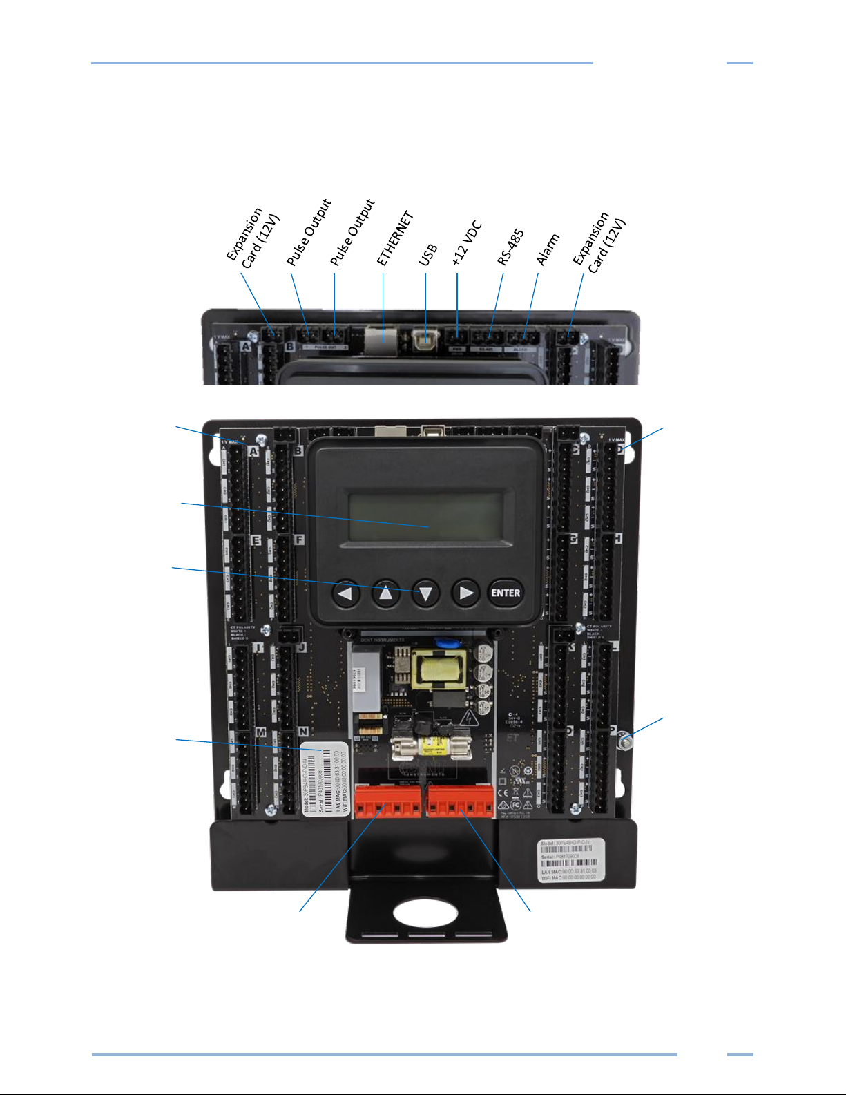
Power Meter Anatomy
All user connections are made on the circuit board. Connectors are identified by function and include
polarity markers.
Element ID
Element ID
LCD Display
Navigation
Buttons
Plate
Ground
Serial #
Model #
MAC ID(s)
Voltage
Input 1
Voltage
Input 2
SPB48 (mounting plate version shown)
Page 7
7
Introduction
Power Meter Safety Summary and Specifications
This general safety information is to
be used by both the Logger operator
and servicing personnel. Setra
Systems, Inc. assumes no liability for
user’s failure to comply with these
safety guidelines.
SPS12-B-y-z, SPS12-C-y-z
SPB48-B-y-z, SPB48-C-y-z
SPS12-C-y-z
SPB48-C-y-z
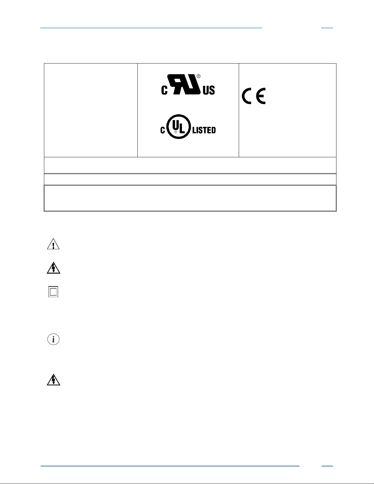
The Meter Family conforms to the
following:
Setra Power Meter Series:
Conforms to UL Std 61010-1, 3rd
Edition
Certified to CSA Std C22.2 No.
61010-1, 3rd Edition
Setra Power meters need to be installed in a user-supplied UL Listed/ uR Recognized enclosure in order to comply with
NEC and local electrical codes.
The Setra Power Meter is an Over-Voltage Category III device. Use approved protection when operating the device.
CAUTION: THIS METER MAY CONTAIN LIFE THREATENING VOLTAGES. QUALIFIED PERSONNEL MUST DISCONNECT
ALL HIGH VOLTAGE WIRING BEFORE SERVICING THE METER WITH THE HIGH VOLTAGE TOUCH SAFE
COVER REMOVED.
Symbols on Equipment
Denotes caution. See manual for a description of the meanings.
DENOTES HIGH VOLTAGE. RISK OF ELECTRICAL SHOCK. LIFE THREATENING VOLTAGES MAY BE PRESENT.
QUALIFIED PERSONNEL ONLY.
Equipment protected throughout by double insulation (IEC 536 Class II).
Symbols in Documentation
Contains additional information pertinent to current subject
DO NOT EXCEED 346V Line to Neutral or 600 volts Line to Line. This meter is equipped to
monitor loads up to 346V L-N. Exceeding this voltage will cause damage to the meter and
danger to the user. Always use a Potential Transformer (PT) for voltages in excess of 346V LN or 600 volts line to line. The Setra meters are 600 Volt Over Voltage Category III device.
Page 8

8
Introduction
MAINTENANCE
There is no required maintenance with the Power Squad 12 or Battalion 48. Abide by the following items:
Cleaning: No cleaning agents, including water, shall be used on the Power Squad 12 or Battalion 48.
If the meter appears damaged or defective, first disconnect all power to the meter. Then call or email technical
support for assistance.
Setra Systems, Inc.
Boxborough, MA USA
Phone: 1-800-257-3872
www.setra.com
Email: techsupport@setra.com
Page 9
9
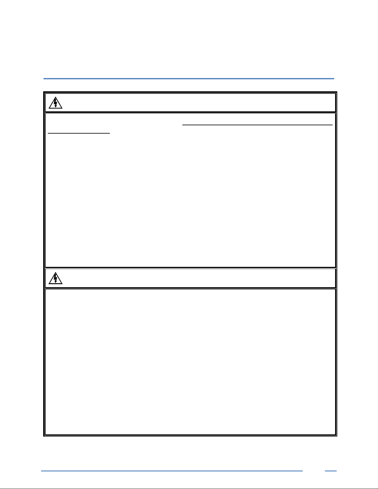
METER SAFETY
Building Service Safety Requirements (Load Center, etc.)
Equipment intended for use with field-installed current transformers that could be installed in panel
boards or switchgears shall observe the following:
Always open or disconnect circuit from power-distribution system (or service) of building before
installing or servicing current transformers.
A circuit breaker used as a disconnect must meet the requirements of IEC 60947-1 and IEC 60947-3
(Clause 6.11.4.2)
Current transformers may not be installed in equipment where they exceed 75 percent of the wiring
space of any cross-sectional area within the equipment.
Current transformers may not be installed in an area where they block ventilation openings.
Current transformers may not be installed in an area of breaker arc venting.
Not suitable for Class 2 wiring method nor intended for connection to Class 2 equipment.
Secure current transformer and route conductors so that they do not directly contact live terminals or
bus.
CTs shall be listed to UL2808
Meter Installation Safety Requirements
Setra meters must be installed in accordance with local electrical codes.
Use copper conductors only.
Connection to the mains terminals shall be made with 14 AWG minimum wire gauge.
External secondary inputs and outputs should be connected to devices meeting the requirements of
IEC 60950
The following additional requirements apply for Recognized board versions of the Setra meter
1) For use only with Listed Energy-monitoring Current Transformers
2) Associated leads of the current transformers shall be maintained within the same overall
enclosure.
3) Unless the current transformers and its leads have been evaluated for REINFORCED
INSULATION, the leads must be segregated or insulated from different circuits.
4) The current transformers are intended for installation within the same enclosure as the
equipment. These may not be installed within switchgears and panel boards” or similar.
Page 10
10
Planning for Field Installation
PLANNING FOR FIELD INSTALLATION
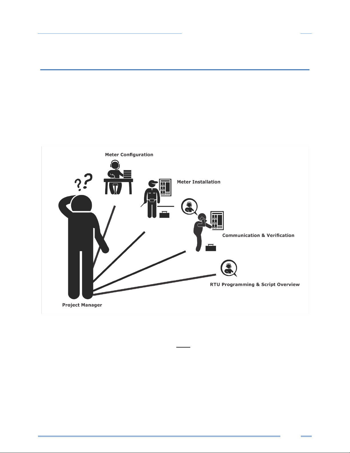
Project Manager Aspects
Meter installation often includes coordination between individuals or groups of people with different
responsibilities. Spend a few minutes considering who will be executing each portion of the installation
and what tools are needed at each stage. Things to consider include determining how to communicate
with the meter, setting address configuration, installing Headstart, access to passwords, etc. The more
tasks completed before installation means less time in the field. The following section gives an overview
of these activities followed by details in the next section.
CONFIGURATION & DATA VIEWING OPTIONS
The Power Squad 12 and Battalion 48 meters have three methods for configuration and data viewing.
The most powerful interface is provided with a PC, Laptop or Tablet running Windows and is encouraged
for complex installations. The second interface is intended for smart phones or tablets that can connect
over USB or Ethernet. The third interface (LCD) is intended for intermittent end user observation and is
restricted in capability. The RTU can also be used for configuration if communication settings are already
established. The feature set of each interface is summarized next.
Page 11

11
Planning for Field Installation
INFORMATION ACCESS BY INTERFACE TYPE
Setra Interface Options
Customer
Device
PC or Laptop Running
Headstart Software
Smart Device or Tablet
via
WebPage
LCD on Meter
(if equipped)
RTU
(Host System)
Modbus /BACnet
When
Used
Meter Setup
Field Visit
Field Visit
End User
Building
System
Real Time Values
All Meter Parameters
Waveform Capture
Harmonic Analysis
All Element View
Phasor Plot
All Meter Parameters
Multi Element View
Voltage
Current
VA
VAR
kWh
Single Element View
All Meter Parameters
Configuration
Entire Meter
Visual Guides
Copy / Paste
Entire Meter
Text Based
Communications Only
Entire Meter
Register Based
Security PINs
Enforced
Factory Support – Level 3
Read Only – Level 1*
Read / Write – Level 2*
Read Only – Level 1*
Read / Write Level 2*
(limited to communication)
Factory Support – Level 3
* If PINs are configured
Page 12
12
Planning for Field Installation
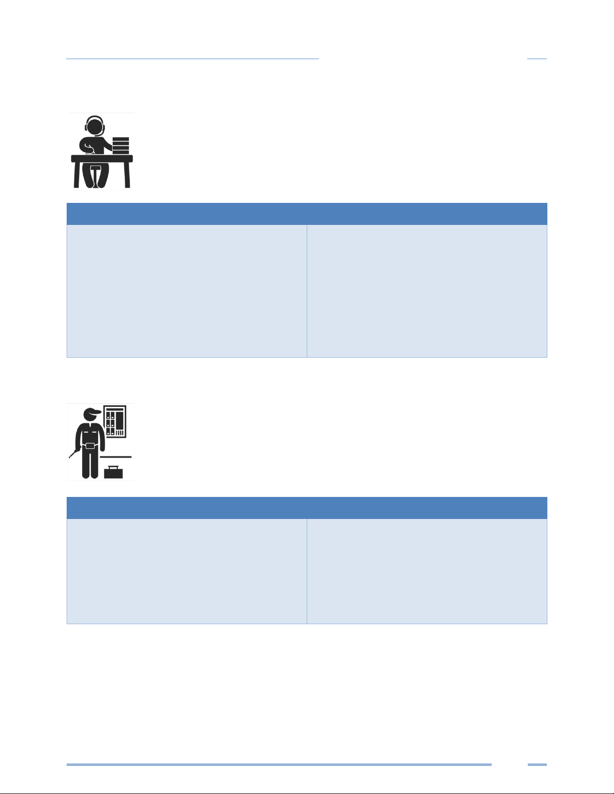
Meter Configuration Overview
▪ Work performed ahead of the installation saves time in the field and results in fewer
mistakes!
Tools
Typical Work
• Desktop or Laptop PC
• USB Type AB Cable (preferred) or
Ethernet & USB wall charger (> 500 mA)
• Thumb Drive (Headstart Installer)
• Electrical Schematics of project
• Installation of Headstart Software
• Connect USB/Ethernet cable from PC to
meter
• Establish communication with meter
• Firmware update (if desired)
• Configure software for anticipated meter
setup
• Field wiring documentation
Meter Installation Overview
▪ Performed by licensed electrician.
Tools
Typical Work
• Mounting hardware (customer supplied)
• Wiring & supplies, labels, wire ties
• Tablet, Smart Device, or
Laptop PC
• Multi Meter, Current Clamp
• Camera
• Mechanical mounting
• Electrical installation
• Install voltage cover
• Apply power to meter
• Confirm basic operation of meter
Page 13
13
Planning for Field Installation
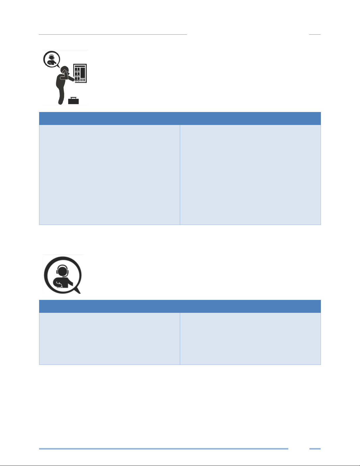
Verification & Communication Overview
▪ Can be modified with power applied to the meter.
Tools
Typical Work
• Tablet, Smart Device (Web Page Based), or
Laptop PC (Headstart Software)
• On site trouble shooting
• Multi Meter, Current Clamp
• Camera
• Locate the power meter
• Confirm RTU device
• Add wire terminations (if required)
• Confirm meter communication settings
• Meter health metrics (check for setup
errors)
• Analytics (Headstart Software)
• Correct instrumentation
• Set security PINs
• Checklist
RTU Programming and Scripting Overview
Tools
Typical Work
• Laptop PC (Remote Access to RTU)
• Remote trouble shooting
• Register List
• Confirm meter communication settings
• Confirm communication protocols
• Exercise remote connectivity
• Run configuration scripting
• Confirm data integrity
Page 14
14
METER CONFIGURATION - DETAILS
This section is written to support setting up the SPS12 and SPB48 in an office
environment and configuring the power meter for a pre-determined configuration. In
many cases the setup is standardized for an organization or project. In other cases, the
setup can be documented and forwarded to an electrician as a wiring schedule. The
setup can also be performed on site and reflect “as built” configurations.
Install the Software
Insert the Headstart thumb drive into the computer or download from https://www.setra.com
The installer should start automatically. If it does not, browse the thumb drive and locate the
HeadstartInstaller.exe program. Start the installer by double-clicking HeadstartInstaller.exe and follow
the installer instructions.
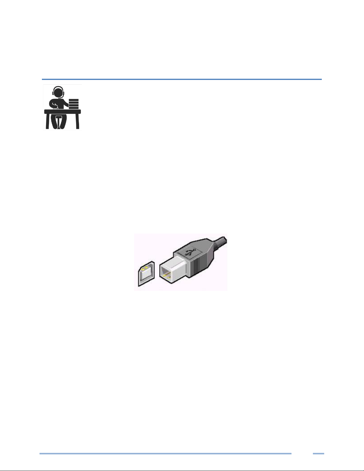
Connect the Meter using USB (Power & Communications)
Preferred Connection via USB AB Cable
The preferred method for configuring the meter from a locally connected computer is through the USB
interface which provides power to the meter as well as communications. The meter will draw 500mA
from the USB port which may overload “out of spec” USB hosts. If the meter fails to power from USB,
the alternate method (described below) must be used.
1) Plug the meter into the USB port (Setra Systems will appear on the LCD (if equipped).
2) Launch the Headstart application and press the “CONNECT USING USB” button on the pop-up
window.
The meter should now be communicating. Headstart is an intuitive application, read the Headstart
overview section (below) for additional information on configuring the meter.
Page 15
15
Meter Configuration
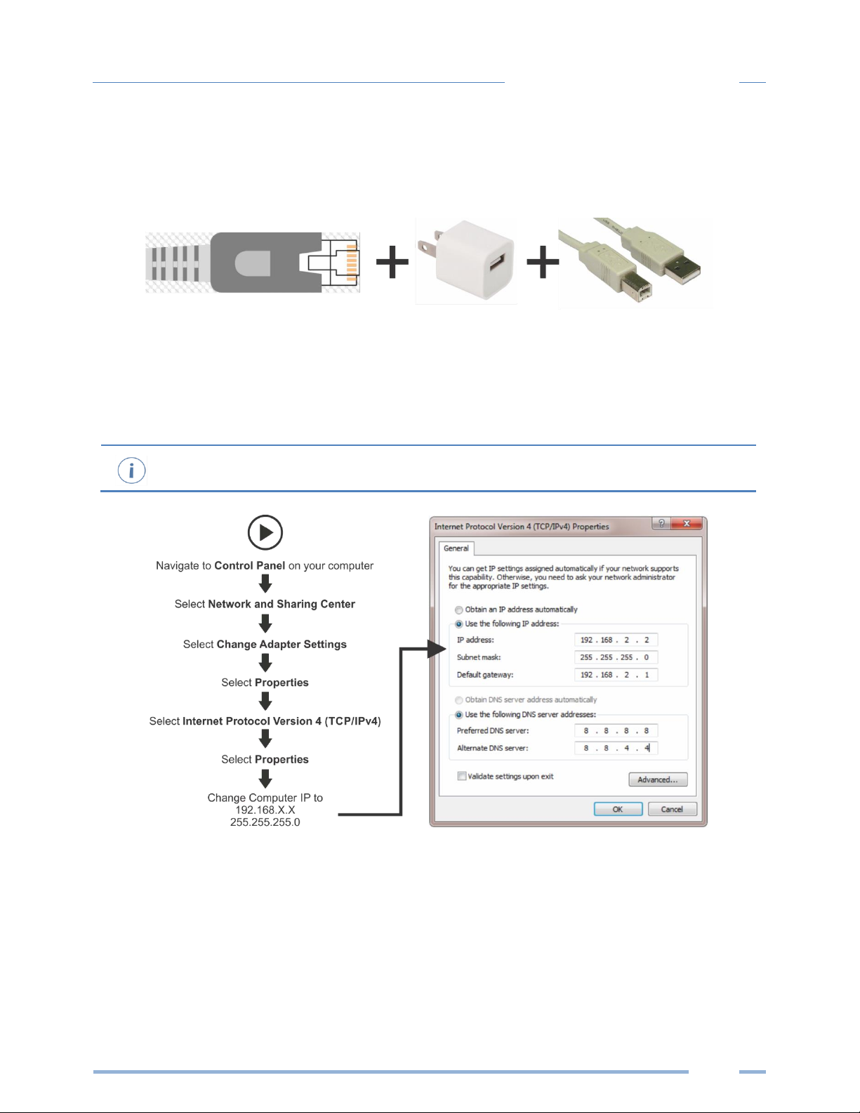
ALTERNATE CONNECTION
If configuration using USB is not available, the Ethernet connection can also be used provided the meter
can be powered from a voltage source such as a customer-supplied USB wall charger (>500mA) or from
AC power, if the meter is already installed.
Alternate Connection
1) Connect the meter to an Ethernet LAN Router running a DNS Server.
2) Apply power to the meter.
3) Observe the IP address displayed on the LCD screen (Splash Screen) or navigate to About Meter
using the meter push button interface (see Appendix A).
You may also connect directly to a Laptop or Desktop PC, but your IP Address and Subnet must
match the meter to connect to it (summarized below).
4) Launch the Headstart application and press the “CONNECT USING ETHERNET” button on the pop
up window.
5) The meter should now be communicating. Headstart is an intuitive application; read the
Headstart overview section (below) for additional information on configuring the meter.
Page 16
16
Meter Configuration
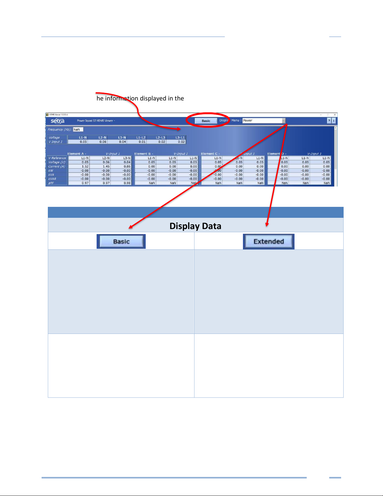
Headstart Software Overview
Headstart is a Windows application and is the most versatile software tool for configuring and verifying
a Setra meter. All functions and menus are accessed under the central drop-down list which has a
content filter for viewing basic metering data or extended data that can be helpful in
troubleshooting. The information displayed in the drop-down list for each filter setting is summarized
below.
Display Data
Real Time Values
Power
Energy
Demand
Real Time Values
Power
Energy
Demand
Power Factor
Waveform Capture
Harmonics
Meter Setup
Communication Setup
Connect to Meter
Advanced
About the Meter
Meter Setup
Communication Setup
Connect to Meter
Advanced
About the Meter
Page 17

17
Meter Configuration
Headstart Documentation
Headstart is an intuitive and self-describing interface that uses context help to facilitate rapid and
accurate configuration via the configuration aids described below.
Help Aids
Information
This button toggles the context pop-up window which
displays the technical description of the parameter or the
register number associated with the reported value. The
window is resizable and movable.
CT Type
Current Transformer models are selected in the
drop-down list and are identified by a combination of a CT
image and the product ratings.
The parameters for the selected CT are automatically
populated. This information can be edited for custom use.
Service Type
Select a service type from the drop-down list. A selection
populates the fields with pre-configured service type
information. User-selectable fields are shown in white.
Greyed out fields indicate restrictions imposed by the
meter.
Wiring Diagrams
Diagrams of different wiring configurations, such as
illustrated here, are available directly within the software
for quick reference.
Page 18

18
Meter Configuration
Configuring Communications using Headstart
Navigate to Communication Setupunder the Display Menu List Box
RS-485
OR
ETHERNET
RS-485 Ethernet
Modbus
OR
BACnet
Modbus
OR
BACnet
Modbus BACnet Modbus BACnet
Set Serial Settings
Set Modbus Address
Set Serial Settings
Set Device ID
Set Max Masters
(optional)
Set Max Info Frames
(optional)
DHCP
OR
STATIC
Set Modbus Port
(optional)
Set Device ID
DHCP Static IP
Set Static Address
Set Subnet Mask
Set Gateway Mask
Press SEND SETUP TO METER
Set MS/TP Address
Set BACnet Port
(optional)
Page 19

19
Meter Configuration
Web Application Overview
The Setra power meter hosts a Web Application that can be accessed by any smart device running a web
browser. The web application can be accessed by using the USB or Ethernet port (Wi-Fi connectivity is
under development).
CONNECT TO WEB APPLICATION USING USB
1) Connect your smart device to the meter
2) Open a Web Browser
3) Enter http://169.254.1.5 (this is the static address of the internal web server)
CONNECT TO WEB APPLICATION USING ETHERNET
1) Discover the I.P. address of the meter
a. Navigate to About Meter on the LCD menu.
b. Use a network discovery tool to find the address by connecting and disconnecting the
Ethernet cable.
c. Set the meter to a static address using another interface.
2) Connect your smart device to the same subnet as the meter
3) Open a Web Browser
4) Enter the SPS12 or SPB48 Ethernet address into the web browser
AUTHENTICATION
Because the Web App can be viewed and controlled by any smart device, and communicates in parallel
to the host system, the meter can be configured to require a PIN# to restrict access the meter.
Enter the PIN#, if assigned, or leave blank, if unassigned, and press the Login button.
Organizationally, the Web App works much the same as Headstart, although it has no analytics and
operates on a single element at a time.
Page 20

20
Meter Installation
METER INSTALLATION - DETAILS
This section is intended to support the physical installation of the meter and
provide guidance on connecting the current transformers (CTs) correctly within
the electrical load center and to the meter.
Meter Mounting Configurations
Setra Power meters are sold in several form factors. Enclosures are designed to be wall mounted and
connected to electrical conduit. Plate mounted versions are ready to be mounted inside a customer
supplied NEMA enclosure and offer IP20 protection. Care should be taken not to flex the circuit board
during mounting.
Mounting Options
PS48 HD
PS12 HD
Enclosure
OEM Plate
Not Yet Available
Page 21

21
Meter Installation
INSTALLATION SEQUENCE
The following section illustrates the SPS12 model. The SPB48 components are slightly different, but
follow the same procedure.
STEP 1) Remove top cover screws (4x) and high voltage cover screws (2x) – provided
STEP 2) Locate, mark, and drill wall mounting points (2x–6x—customer supplied)
The plastic enclosure itself can be used as a template for marking the drill locations on the wall.
If the meter is not available for use as a drill template, a drawing indicating the spacing between
mounting holes can be found in the appendix. The centerline holes are intended for fastening to wall
studs. If hollow wall fasteners are used, the outer 4 mounting points are recommended.
#8 Fastener
Page 22

22
Meter Installation
STEP 3) Mount conduit fittings, conduits, and blanking plugs
STEP 4) Connect voltage leads
DO NOT ENERGIZE METER WITH VOLTAGE COVER REMOVED
Page 23

23
Meter Installation
STEP 5) Attach high voltage cover
STEP 6) Connect CT and Communications Wiring
CONNECTING VOLTAGE
Connect the voltage leads (L1, L2, L3, and N, as necessary) to the meter through a dedicated disconnect
or circuit breaker. A voltage lead of 14 AWG THHN Minimum 600VAC rating (or equivalent) is required.
IMPORTANT: Verify the circuit breaker is marked as the disconnect breaker for the meter.
IP30
TOUCH SAFE (with internal cover installed)
Page 24

24
Meter Installation
Wiring the Setra Meter in a 3-wire, Split ɸ Service Panel
High voltage MAY BE PRESENT. Risk of electric shock. Life threatening voltages may be
present. Qualified personnel only.
Illustrating the intended wiring configuration for each of the Service Types
available in the Service drop-down list under “Meter Setup”
EXAMPLE LOADS:
Single Phase L1-N or L2-N 110 VAC: Lighting, Appliance, Living Zone
Single Phase L1–L2 220 VAC: Water Heater, Clothes Dryer, Equipment with no neutral wire.
Split Phase L1–L2 220 VAC: Service Entrance, Equipment with neutral wire.
3-Wire, 1 Phase used
On MAINS
L1-N, L2-N
(RōCoils Shown)
Single Phase
110 VAC Plug Loads
L1-N or L2-N
Single Phase
220 VAC Plug Load
L1-L2
Meter is powered
from L1 to L2 on
the V Input 1
terminal
(Label as Disconnect))
Connect the
Neutral wire to
V INPUT 1 (N) on
the meter
3-Wire, 1 Phase
Split Load
L1-N, L2-N
Page 25

25
Meter Installation
Wiring the Setra Meter in a 4-wire, 3 ɸ Service Panel
Illustrating the intended wiring configuration for each of the Service Types
available in the Service drop-down list under “Meter Setup”
Note: The Setra Meter Series uses the “Neutral” Terminal as a voltage reference. For systems
without a neutral conductor, Setra Systems suggests connecting a ground wire to this
terminal. If the neutral terminal is left open, L-L measurements will be accurate, but L-N
measurements may not be symmetric. If a ground wire is connected to the Neutral terminal,
<2mA will flow into the ground wire.
Connect the
Neutral wire
or Ground wire to
V INPUT 1 (N) on
the SPS12 or SPB
48 meter
Meter Power
Connect all phases
to the V INPUT 1
terminal
(Label as Disconnect)
3-Wire, 3 ɸ
DELTA load
(No possibility of
Neutral Current)
L1-N, L2-N(est), L3-N
3 Wire, 3 ɸ used
On MAINS
L1-N, L2-N, L3-N
(RōCoils Shown)
Single Phase
Branch Loads
L1-N
4 Wire, 3 ɸ
WYE load
(Neutral Current)
L1-N, L2-N, L3-N
Page 26

26
Meter Installation
Current Transformer Basics
Ensure CTs meet the following criteria:
▪ 600 VAC UL Rated
▪ UL2808 Listed
▪ 1/3 (333 mV) output voltage
▪ Appropriate range for the circuit (5-120% of CT Rating
Recommended)
▪ Read the label
Ensure CT orientation & placement:
▪ Arrow points toward load (or as instructed by CT label)
▪ Arrow points away from Panel (or as instructed by CT label)
▪ Placed on First Conductor of voltage Reference (L1-L2) circuits are
placed on L1
▪ Observe wiring color and polarity
▪ Use the Shield wire if provided (connect to PCB terminal marked S)
Wiring Guide for CT Types
Split, Hinged, & Solid Core CTs
Rogowski CTs
White: Positive
Black: Negative
(no shield)
Red: Positive
Black: Negative
Bare Wire: Shield
Page 27

27
Meter Installation
Wiring the CTs to the Setra Meter
The image below is the counterpart to the service panel illustration and indicates how to connect CTs to
the SPS12 & SPB48 meters for each service type. For service types that are not specifically listed, it is
recommended to choose “single phase” service and configure each channel individually. Three phase
loads are illustrated on the left and split phase loads on the right as an example only. Elements are fully
interchangeable on the meter.
Page 28

28
Communication & Verification
COMMUNICATION & VERIFICATION - DETAILS
This section is intended to support the commissioning of the SPS12 & SPB48 meters
by an instrumentation technician. In many cases, the electrical installation is
conducted ahead of the availability of the RTU or was performed by a different
installer. Often the technician is working in concert with a remote programmer who
is confirming the connectivity with a remote host system. A Digital Multi Meter
(DMM) can be used to confirm measurements at the board terminals, if necessary.
It is assumed that the meter is now powered up from the line voltage.
It is safe to touch the meter (including the user buttons) with the top
cover removed ONLY IF THE INTERNAL HIGH VOTLAGE COVER IS
INSTALLED.
Communications settings and real-time data values can be confirmed quickly using the LCD
interface. If significant setup modifications are anticipated, a computer interface is
recommended.
Physical Connections on an RS-485 Multidrop Network
The Setra meter uses a 2-Wire Half Duplex RS-485 Implementation.
▪ Termination Resistors—are NOT included on the meter. If the meter is at the end of a daisy-
chain, then connect a 120-ohm leaded resistor between the + and – terminal at the connector.
▪ Bias Resistors—are NOT included on the meter. Bias resistors are needed If the idle conditions
of the bus are in an indeterminant logic voltage. Bias resistors are usually located at the master
node and are usually 680 ohms for a RS-485 network.
▪ Network Topology—RS-485 is designed to be implemented as a daisy chain (series connections)
rather than star or cascade topologies.
▪ Signal Names—Some RS-485 devices use the terminology A/B while others use +/-. Note that A
is (-) and B is (+). Many manufacturers incorrectly label the terminals.
▪ Bus Loading—The meter is a 1/8
th
unit load allowing up to 256 like devices in parallel.
2-Wire Multidrop Network using Terminating Resistors
Page 29

29
Communication & Verification
Communication Verification
Verification includes confirmation of BOTH the physical interface settings (Serial or Ethernet)
and the protocol (Modbus or BACnet) settings.
The LCD User interface can be used to quickly confirm the settings required for each combination of
interface and protocol. The interface is intuitive and groups together commonly associated registers.
The complete interface is presented in Appendix A as a navigational map. Arrows indicate how to move
from one menu display to the next. A Reverse Contrast entry in the documentation indicates the active
menu item in a list which corresponds to a blinking character in the physical LCD. The ENTER button is
used to select a property and up / down buttons are used to select among the values supported by the
meter. Note that changes to the meter configuration are limited to the communication interface using
the LCD. If additional changes (such as CT type) are required they must be made using a software
interface.
Example LCD Navigation
HEADSTART / WEB APPLICATION
If your meter does not include the LCD user interface or if you prefer to verify the installation using
software then verification is facilitated through the Headstart PC application or the Web App which
shares a common design. Refer to the section on Configuration Details (starting on page 14.
Page 30

30
Communication & Verification
Physical Interface Verification
SERIAL SETUP VERIFICATION
In a multidrop serial network, the host data format settings are typically known or specified and the
slave is adjusted to match. In some cases (long wiring runs, etc.), it may be necessary to experiment in
determining the fastest allowable baud rate for a given wiring configuration by changing BOTH the host
and slave devices. Configurations other than 8N1 are rare, it is advised to use this configuration for Data
Bits, Parity and Number of Stop bits, if possible.
LAN ETHERNET NETWORK VERIFICATION
The SPS12 & SPB48 meters communicate using IEEE 802.3 Ethernet connectivity running at a 10/100
Mbps. Verification of the meter settings over Ethernet include ensuring that the I.P. address of the
meter is within a range that allows communication with a host (if static) or set for DHCP allowing the
meter to be assigned an address by a DHCP server as described below.
DHCP
If the meter is configured for Dynamic Host Configuration Protocol (DHCP) when the meter is powered
on or the Ethernet cable is inserted the meter is assigned an IP address by the DHCP server. This address
appears on the meter LCD or can be found through connection with Headstart or the Web App. The IP
address assigned to the meter should be regarded as a temporary address as the address may change
between power cycles making it difficult for the host system to know how to find the meter on the
network. One common approach is to set the meter for DHCP so that the address can be assigned by a
DHCP server and then change that IP address to static once the connection is made. The meters are set
to use DHCP as a default setting to facilitate this approach.
STATIC IP
If the meter is set to a static I.P. then its address should be assigned by an IT department to avoid
multiple devices on the same network. This scheme is usually used when an RTU is expecting to find the
meter at a specific IP address.
Page 31

31
Communication & Verification
Protocol Verification
The network protocol is typically specified as part of the installation. BACnet MS/TP and Modbus RTU
are the two communication protocols that operate over an RS-485 serial network and BACnet IP and
Modbus TCP are the protocols over Ethernet. Each combination of interface and protocol require
specific registers settings described below. The scope of this section is to use either the LCD interface or
software tools to quickly confirm or change settings to match an existing specification. Further
information and optimization tips are covered in the section on RTU programming.
Modbus Settings
MODBUS RTU SETTINGS
Device Address: In a Modbus network each device must be assigned a unique slave address. The slave
address sets the register address for ELEMENT A. Adjacent elements B, C, D, etc. are accessed by
incrementing the slave address by 1. The slave address of the meter needs to be set to match the
address expected by the RTU and is normally part of the network specification. The default address for
element A is 1.
MODBUS TCP SETTINGS
Modbus Port: The meters uses the industry standard Port 502 for Modbus. This port number can be
changed, although this is considered an advanced setting and should be left at 502 unless this generates
a conflict on the host system. The port number can only be changed through a software interface.
BACnet Settings
BACnet Device ID: In a BACnet network each device must be assigned a unique Device ID and is
common to BACnet MS/TP and BACnet IP protocols. Besides the standard ability to change this from a
BACnet explorer tool it may be changed via the Viewer, Web App, or LCD.
BACNET MSTP
Max Masters: The default setting is 127 and does not usually need to be changed.
Max Info Frame: The default setting is 1 and does not usually need to be changed.
BACNET IP
BACnet Port: The BACnet default port is 47808 and does not usually need to be changed
BBMD: The BACnet/IP Broadcast Management Device is set to 0.0.0.0 at default and can be changed
through a software tool to allow discovery across networks.
Page 32

32
Communication & Verification
Pulse Outputs
Pulse outputs are available to export energy consumption data to
generic accumulators that cannot communicate using a data
interface. For example: this interface could be used by a data
aggregator that is measuring natural gas and electricity.
The SPB48 meter has two pulse outputs that can be configured
to report the total imported energy on any element. The output
will produce a 50 mSec duration pulse every time the energy has
reached a threshold value. This value is computed based on the
meter configuration and reported as a read only register (see the
register list Excel file). The pulse output will only be initiated on
1 second intervals.
1 Sec
Pulse Outputs
2 Sec
50 mSec
3 Sec 4 Sec ... Sec
Typical Pulse Sequence
OPEN COLLECTOR OUTPUT
The pulse output is electrically isolated from the meter power supply and requires the user to connect a
voltage source (5–30 VDC), a ground wire (connected to the host ground), and a pullup resistor. A 10K
resistor is the recommended value. The pullup resistor shall be sized to limit the current through the
isolator to 5 mA.
If the collector is connected directly to a source of voltage, the pulse isolator will immediately
burn out and become non-responsive.
Output Connections
Page 33

33
Communication & Verification
ALARM (SPDT)
Some models of the Setra meter include a single pole double throw electromechanical relay that can be
configured to trigger under loss of voltage conditions. This feature will alert building systems to a “loss
of phase” condition within 100 mSec of occurrence without being polled. Once triggered this relay will
need to be reset via a register command. This feature is under development and is expected to be
available in early 2018.
12 Volt Auxiliary Power
The meter provides an auxiliary 12 volt output that is derived from an auxiliary winding on the meters
line connected power supply. The 12 volt supply voltage is unregulated but protected by a selfresetting fuse. The purpose of the supply is to power external radio equipment or provide supply
voltage for analog sensors such as 4-20 ma current loop devices. If full rated current is drawn from this
terminal the minimum operating voltage of the L1-L2 power supply is 100 VAC.
Page 34

34
Communication & Verification
Security PIN Protection
The SPB48 has three levels of PIN protection that users can choose to assign for restricting access to
meter information. The default meter configuration is NO PIN (code 0000). PINs are 4 digits and are
stored as a user setting in the non-volatile memory of the meter. PINs are also accessible as registers but
are encoded so that reading the value of the register through an RTU does not inform a user what the
password is. This feature allows Setra to support looking up forgotten PINs, if network access is
available.
ACCESS RESTRICTION LIMITATIONS
If security levels have been set up in the meter, no data is accessible through the LCD user interface or
web page without entering the PIN credentials. Note, however, that protocols such as Modbus do NOT
SUPPORT ANY LEVEL OF security such that any network traffic acting as a master can retrieve and write
data from the registers. Generally, this will require knowledge of the IP address or slave ID and the
register list which discourages casual intrusion. Factory level registers cannot be over-written by the RTU
without a factory PIN.
HEADSTART – UNRESTRICTED ACCESS
The Headstart software tool can be used to read & write configuration information to the meter without
entering credentials.
Headstart is the preferred tool for setting up access restrictions because it allows users to test
the function of the PINs without locking themselves out from the ability to change the PIN.
USING THE PERMISSION REGISTERS
The Setra meter uses both a “Read Only” register and a “Read / Write” register to compare against user
entrees from the LCD keypad or the Web App form entry. Both internal permission registers have a
default value of [0000]. A consequence of this is that both PIN registers need to be configured (i.e.
changed from defaults) to implement a read only PIN, otherwise the situation may occur where a user is
intended to be restricted to Read Only but accidentally promoted to Read /Write because the PIN
matches the default response value. Headstart and the Web App disallow this condition but remote
programmers using direct register access may create this condition.
READ ONLY PERMISSION REGISTER
Configuring the meter for a Read Only user allows data or configuration items to be viewed but not
changed. This level of authorization might be appropriate for general end users such as building owners
who may not be aware of the details of the installation. It is recommended to use Headstart to configure
permissions although it is also possible to set up a Read Only PIN using the Web App if a Read/ Write PIN
has already been entered (either through the LCD or the Web App itself).
Page 35

35
Communication & Verification
READ/WRITE PERMISSION REGISTER
Read/Write permissions allow users to read and write configuration items and to set new PINs for other
users. This level of authorization will be required by any technician or user who needs the ability to
correct setup errors in the meter. The default PINs [0000] allow new users to reset the Read / Write PIN
from either the Web App or Headstart. Permissions cannot be set through the LCD interface.
Page 36

36
Communication & Verification
Verification of CT Installation
Once the meter is configured and communicating with the RTU, it is a good idea to perform some simple
checks to ensure that all the CTs are on the correct voltage phases and that the CTs are facing the
correct direction. The following are recommendations that work for typical installations. Special circuit
conditions, like unloaded motors, may indicate an installation error when none exists. A Digital
Multimeter (DMM) can be used to confirm these cases.
INSTALLATION PHASE VERIFICATION
The meter includes a PhaseChek™ algorithm that identifies any element that the meter suspects may be
incorrectly phased (i.e., the CT is associated with the wrong voltage source or is physically on the wrong
wire) based on power factors below 0.55. This feature is accessed using the LCD interface by navigating
to “VERIFY INSTALLATION” and pressing the ENTER button. The LCD display will list the elements having
at least one channel with a low power factor.
CHECK ELEMENTS
A EF
Use the navigation buttons to highlight a specific element and hit enter or just hit enter and move from
element to element using the / keys. Within each element (identified on the top line of the
display) the status of each channel is identified as good (PF > 0.55) or bad (PF < 0.55).
ELEMENT F
CH1 Good
CH2 Bad
CH3 Bad
Two “Bad” channels are often an indication that two CTs are inadvertently swapped. When the power
factor for all enabled channels is greater than 0.55 then the meter reports
CHECK ELEMENTS
ALL CHANNELS GOOD
PhaseChek™ is only applied for elements that are enabled. VIEW METER SETUP on the LCD
screen can be used to ensure that all intended elements are active. PhaseChek™ is advisory
only. It is possible that the power factor for a particular load is truly less than 0.55, as may be
observed in a free running motor.
Headstart and the Web App run PhaseChek™ continuously on all enabled elements and report low
power factor in the real time values table by turning the text RED or by a using a red indicator.
Page 37

37
Communication & Verification
PHASE CHECKING BY PHASER PLOT
When a CT is installed on the incorrect phase, the indicated current vector is pointing either 180 degrees
away (a split phase system) or 120 degrees away (a three-phase system) from the true displacement
angle. In the latter case, this usually causes a significant decrease in the reported power factor, even if
the CT is also on backwards. When the absolute displacement power factor of a load is below 0.55 (an
angle greater than 57 degrees between voltage and current) the meter will flag it as a phasing error.
Headstart has a PhasorPlot feature that can be used to study the voltage and current vectors of a given
meter element.
Check for Low Power Factor
▪ Headstart: Real Time Values > (All power factors < 0.55 are shown in RED)
▪ Web App: Real Time Values > (All power factors < 0.55 are shown in RED)
▪ LCD: Verify Installation > (LCD will list all elements having a PF < 0.55)
Electrical Power Quadrants with Incorrect CT Phase shown
Page 38

38
Communication & Verification
CT Orientation Check
The meter reports power and energy in each electrical quadrant under a different register. When CTs
are installed backwards, the indicated current vector is oriented 180 degrees away from the true
displacement angle. In accordance with standard definitions, the Wattage and VARs of the effected
channel report with a sign opposite from what is expected. Often this means that the import registers
will be reading zero while the export registers are showing a value. Note that backward CTs have no
impact on the amplitude of the Power Factor. A moderate power factor (>0.7) in concert with a negative
power is a clue that the CT is on backwards, but is on the correct phase.
Electrical Power Quadrants with Reversed CT shown
Check that the wattage has the correct sign (Designated + for loads)
▪ Headstart: Real Time Values > (Confirm Sign of Power For All Elements)
▪ Web App: Real Time Values > (Confirm Sign of Power For All Elements)
▪ LCD: Real Time Values > (Confirm Sign of Power for Each Element)
If a CT is discovered to be on backwards after the installation is complete, the direction of the
CT can be reversed through a user configuration register designed for this purpose, called the
“Flipper,” located at 2226, 2234, and 2235.
Page 39

39
RTU Programming & Scripting
RTU PROGRAMMING AND SCRIPTING - DETAILS
This section is intended for the programmer of the RTU or host system and includes
details about meter and element addressing, register locations, data formats and
protocol examples.
Register Organization
The meter communicates through the reading and writing of registers. Registers are organized into
functional groups and are compliant with the SunSpec Modbus interface model.
▪ SunSpec Common Registers
▪ SunSpec TCP Network Stack Registers
▪ SunSpec Serial Interface Registers
▪ SunSpec Energy Meter
▪ Setra Factory Registers
▪ Setra User Command Registers
▪ Setra User Configuration Registers
▪ Setra Metrology Registers
▪ Setra Daughter Card Registers
▪ Setra Waveform Capture Registers
The complete register set is included as an Excel file on the supplied thumb drive or at:
https://www.setra.com
ELEMENT VS SYSTEM SCOPE
Element
When reading the value of a register, the scope is defined as belonging to an “Element” if each Modbus
Slave Address (or BACnet object instance) contains a unique value. Physically speaking, elements are
grouped into sets of threes and given alphabetic assignments (A, B, C, etc.). and are marked on the silk
screen of the circuit board. Registers that contain data inclusive of more than one channel are identified
as being either SUMS or AVERAGES of the enabled channels within an element.
Channel
Channels are identified on the circuit board as CH1, CH2, or CH3 and represent physical CT inputs. In
three phase system configurations, these correspond to a current load on a corresponding line voltage.
In single phase configurations, they are just used to identify a CT location. Registers providing data for
an individual channel are also described as elements in their scope as a unique value exists for each
Slave Address or BACnet object instance.
System
The term “System” refers to registers defining the characteristics of the entire circuit board. System
registers report the same value independent of the slave address.
Page 40

40
RTU Programming & Scripting
CONFIGURING ELEMENT AND CHANNEL REGISTER FOR SERVICE TYPES
The Headstart software enforces all element configurations to form a valid electrical system.
Configurations performed by remote systems may produce unexpected results if configurations are
internally inconsistent. The following tables document how to configure element and channel registers
for each service type. Every register should be explicitly written.
Red Text indicates Required Values, Purple Text Indicates Suggested Defaults if this data is not known.
Modbus Absolute Address/BACnet Object Assignments for Setting up Service Types
REGISTER TEMPLATE
Service Type
2207
V_Input
2217
Description
2617
Channels
Volt Ref
CT Type
Range
Phase Shift
CT Multiplier
CT Sign
CH1
2220
2223
2224,2225
2224,2225
2221,2222
2226
CH2
2229
2232
2227,2228
2233,2234
2230,2231
2235
CH3
2238
2241
2236,2237
2242,2243
2239,2240
2244
Configurations
4 Wire 3 ɸ
(Wye)
Service Type
1
V_Input
1 or 2
Description
31 Char
Channels
Volt Ref
CT Type
Range
Phase Shift
CT Multiplier
CT Sign
CH1
L1 – N [1]
mV [1] or RōCoil [2]
Any > 0A
-3.0˚ to +3.0˚
Any > 0 [1]
0 or 1
CH2
L2 – N [2]
mV [1] or RōCoil [2]
Any > 0A
-3.0˚ to +3.0˚
Any > 0 [1]
0 or 1
CH3
L3 – N [3]
mV [1] or RōCoil [2]
Any > 0A
-3.0˚ to +3.0˚
Any > 0 [1]
0 or 1
3 Wire 3 ɸ
(Delta)
Service Type
2
V_Input
1 or 2
Description
31 Char
Channels
Volt Ref
CT Type
Range
Phase Shift
CT Multiplier
CT Sign
CH1
L1 – N [1]
mV [1] or RōCoil [2]
Any > 0A
-3.0˚ to +3.0˚
Any > 0 [1]
0 or 1
CH2
L2 – N [2]
mV [1] or RōCoil [2]
Same as 1
Same as 1
Same as 1
0 or 1
CH3
L3 – N [3]
mV [1] or RōCoil [2]
Same as 1
Same as 1
Same as 1
0 or 1
Even though CH2 is calculated internally it is recommended that the CT settings reflect those from CH1 rather than being left at factory default
to facilitate configuration validation from the RTU.
Page 41

41
RTU Programming & Scripting
2 Wire 1ɸ
(Plug Load)
Service Type
3
V_Input
1 or 2
Description
31 Char
Channels
Volt Ref
CT Type
Range
Phase Shift
CT Multiplier
CT Sign
CH1
ANY [1-6]
mV [1] or RōCoil [2]
Any > 0A
-3.0˚ to +3.0˚
Any > 0 [1]
0 or 1
CH2
ANY [1-6]
mV [1] or RōCoil [2]
Any > 0A
-3.0˚ to +3.0˚
Any > 0 [1]
0 or 1
CH3
ANY [1-6]
mV [1] or RōCoil [2]
Any > 0A
-3.0˚ to +3.0˚
Any > 0 [1]
0 or 1
Any channel that needs to be turned OFF should set the CT Type to OFF.
3 Wire 1 ɸ
(Split Phase)
Service Type
4
V_Input
1 or 2
Description
31 Char
Channels
Volt Ref
CT Type
Range
Phase Shift
CT Multiplier
CT Sign
CH1
L1 – N [1]
mV [1] or RōCoil [2]
Any > 0A
-3.0˚ to +3.0˚
Any > 0 [1]
0 or 1
CH2
L2 – N [2]
mV [1] or RōCoil [2]
Any > 0A
-3.0˚ to +3.0˚
Any > 0 [1]
0 or 1
CH3
L3 – N [3]
OFF [0]
Any > 0A
-3.0˚ to +3.0˚
Any > 0 [1]
0 or 1
Even though CH3 is not used for computation it is recommended that the CT settings reflect those from CH1 rather than being left at factory
default to facilitate configuration validation from the RTU.
Disabled
(OFF)
Service Type
5
V_Input
1 or 2
Description
31 Char
Channels
Volt Ref
CT Type
Range
Phase Shift
CT Multiplier
CT Sign
CH1
L1 – N [1]
OFF [0]
Any > 0A
-3.0˚ to +3.0˚
Any > 0 [1]
0 or 1
CH2
L2 – N [2]
OFF [0]
Any > 0A
-3.0˚ to +3.0˚
Any > 0 [1]
0 or 1
CH3
L3 – N [3]
OFF [0]
Any > 0A
-3.0˚ to +3.0˚
Any > 0 [1]
0 or 1
Even though disabled channels are not used in calculations and report 0.0 they still contain configuration information. It i s suggested that they
be set to a known value rather than left at defaults to facilitate configuration validation by the RTU.
CONFIGURING SYSTEM REGISTERS
Modbus Absolute Address/BACnet Object Assignment
REGISTER TEMPLATE
Description
2601
PF Sign Convention
2248
V1 Multiplier
2203,2204
V2 Multiplier
2205,2206
Configurations
System
Description
31 Char
PF Sign Convention
ANSI [1] or IEEE[2]
V1 Multiplier
Any > 0 [1]
V2 Multiplier
Any > 0 [1]
Page 42

42
RTU Programming & Scripting
Modbus Protocol Commands
If configured for Modbus, the power meter family follows the Modbus RTU protocol and supports the
following command set.
Supported Modbus Commands
Command Name
Command
Number (Hex)
Description
Read Holding Registers
03
Used to read the data values from the meter.
Write Single Register
06
Used to write a single holding register to a meter.
Report Slave ID
11
Used to read information from the identified meter.
SLAVE ADDRESS
Refer to the section “Serial Protocols” for additional information on setting the Slave Address and
finding the address of a specific meter element.
See the Modbus documents in the following online resources.
http://Modbus.org/docs/PI_MBUS_300.pdf
http://www.Modbustools.com/Modbus.html
http://www.simplyModbus.ca/TCP.htm
Page 43

43
RTU Programming & Scripting
BACnet
Building Automation and Control Network (BACnet) protocol was developed under the auspices of the
American Society of Heating, Refrigerating and Air-Conditioning Engineers (ASHRAE) and is recognized as
an American National, European, and ISO global standard.
BACnet Device ID. All device IDs on a BACnet network must be unique. Refer to the section “Serial
Protocols” and refer to the Register List for additional information
Serial
The meters Serial version supports writable max_master and max_info_frames properties in the device
object for MS/TP networks. For best network performance, the max_master should be set to the
highest MS/TP MAC address on the network. The max_info_frames does not need to be changed in
most installations
Ethernet
Ethernet versions can register as Foreign Devices to a BBMD. BBMD stand for BACnet/IP Broadcast
Management Device. The address also can be written to BACnet object identifiers 14014 (BBMD IP
Address LSW) and 14015 (BBMD IP Address MSW).
NOTE: The LSW/MSW are in network order.
For example, to set the BBMD server to 192.168.1.100 you would write:
43200 (0xA8C0) to BBMD IP address LSW object identifier 14014
-and-
25601 to (0x6401) to BBMD IP address MSW object Identifier 14015
This sends the register as foreign device packet with a Time to Live (TTL) of 60000 seconds.
To disable BBMD foreign device registration write 0 to both BBMD IP address LSW (14014) and BBMD
IP address MSW (14015) or simply write 0.0.0.0 to the BBMD field in the Headstart Communications
tab.
The following online BACnet resources are also helpful.
http://www.bacnet.org/
Page 44

44
Appendix A
APPENDIX A—
Page 45

45
Appendix A
MENU NAVIGATION
Page 46

46
Appendix A
Page 47

47
Appendix B
APPENDIX B—ENCLOSURE DIMENSIONS
SPB48 Enclosure Dimensions SPS12 Enclosure Dimensions
Page 48

48
Appendix C
APPENDIX C—MOUNTING TEMPLATES
SPB48 Enclosure Drill Template
Page 49

49
Appendix C
SPS12 Enclosure Drill Template
Page 50

50
Appendix C
SPB48 Plate Template
Page 51

51
Appendix D
APPENDIX D—SPS12 & SPB48 TECHNICAL SPECIFICATIONS
Specification
Description
Service Types
Single Phase, Split Phase, Three Phase-Four Wire (WYE), Three Phase-Three Wire (Delta)
Voltage Channels
90-346 Volts AC Line-to-Neutral, 600V Line-to-Line, CAT III.
Two voltage reference inputs (SPB48 only)
Current Channels
12 (SPS12) or 48 (SPB48) channels, 0.525 VAC max, 333 mV CTs, 0-4,000+Amps depending
on current transducer
Maximum Current Input
150% of current transducer rating (mV CTs) to maintain accuracy. Measure up to 4000A
with Rogowski Coil CTs.
Measurement Type
True RMS using high-speed digital signal processing (DSP) with continuous sampling
Line Frequency
50-60 Hz
Power
From L1 Phase to L2 Phase. 90-600VAC RMS CAT III 50/60Hz, 500mA AC Max
Use of 12 volt auxiliary output requires 100 VAC minimum input voltage.
AC Protection
0.5A Fuse 200kA interrupt capacity
Power Out
Unregulated 12VDC output, 200 mA, self-resetting fuse
Waveform Sampling
1.8 kHz (SPB48), 3.6 HZ (SPS12)
Parameter Update Rate
1 second
Measurements
Volts, Amps, kW, kVAR, kVA, aPF, dPF, kW demand, kVA demand, Import (Received) kWh,
Export (Delivered) kWh, Net kWh, Import (Received) kVAh, Export (Delivered) kVAh, Net
kVAh, Import (Received) kVARh, Export (Delivered) kVARh, Net kVARh, THD, Theta,
Frequency. All parameters for each phase and system total.
Accuracy
0.2% ANSI C12.20-2010 Class 0.2
Resolution
Values reported in IEEE-754 single precision floating point format (32 bit).
Indicators
4-line display, tri-color backlight (PhaseChek™)
Pulse Output
Open Collector, 5mA max current, 40V max open voltage
Alarm Output
Voltage Phase Loss Alarm (SPDT Relay - 30 VDC) (SPB48 only)
Communication
Hardware
RS-485, Ethernet, & USB (for configuration only)
Supported Protocols
Modbus RTU or BACnet Master Slave Token Passing protocol (MS/TP)
Modbus (using SunSpec IEEE-754 single precision floating point model)
Max Communication Length
1200 meters with Data Range of 100K bits/second or less
RS-485 Loading
1/8 unit
Communication Rate (baud)
Modbus: 9600 (Default), 19200, 38400, 57600, 76800, 115200
BACnet: 9600 (Default), 19200, 38400, 76800
Data Bits
8
Page 52

52
Appendix D
Specification
Description
Parity
None, Even, Odd
Stop Bit
2, 1
Termination
None provided
Data Formats
Modbus, BACnet MS/TP, Modbus TCP or BACnet IP
Mechanical
Wire Connections
12-22 AWG 600 VAC, Voltage connection must be #14 AWG or larger & 600 VAC rated
Mounting
Enclosure or Panel Mount (SPB48 only)
High Voltage Cover
IP40
Mounting Plate
SPB48 Only
Operating Temperature
-20 to + 60⁰ C (-4 to 140⁰ F) (the colder the temperature the more voltage needed to
power the board)
Humidity
5% to 95% non-condensing
Enclosure
ABS Plastic, 94-V0 flammability rating, connections sized for 1–inch EMT conduit
Dimensions
(L) 33.7cm x (W) 25.2cm x (H) 8.0 cm (13.3” x 10” x 3.1”) (no enclosure version)
(L) 24.7cm x (W) 25.2cm x (H) 8.0 cm (9.8” x 10” x 3.1”) (no enclosure version)
PCBA Dimensions
(L) 21.6cm x (W) 21.6.0cm x (H) 6.4 cm (8.5” x 8.5” x 2.5”)
ViewPoint HD™ Minimum System Requirements
Operating System
Windows® 7. Windows® 8, Windows® 10
Communications Port
RS-485 & USB standard. Ethernet available. One USB Port required on PC.
Safety
FCC Compliance
This device has been tested and found to comply with the limits for a Class A digital
device, pursuant to part 15 of the FCC Rules. These limits are designed to provide
reasonable protection against harmful interference when the equipment is operated in a
commercial environment. This equipment generates, uses, and can radiate radio
frequency energy and, if not installed and used in accordance with the instruction manual,
may cause harmful interference to radio communications. Operation of this equipment in
a residential area is likely to cause harmful interference in which case the user will be
required to correct the interference at user’s own expense.
Serial/Ethernet Meters
The following are UL Recognized:
SPS12-C-y-z, SPS12-B-y-z, SPB48-C-y-z, SPB48-P-y-z
The following are UL Listed: SPB48-C-y-z , SPB48-C-y-z
Conforms to UL Std 61010-1, 3rd Edition, UL 61010-2-30:2010
Certified to CSA Std C22.2 No. 61010-1, 3rd Edition
SS-SPB48 Rev. A 11/17
Page 53

53
Index
 Loading...