

Page 1
Power Meter
Operating Instructions
Setra Systems, Inc.
159 Swanson Road, Boxborough, MA 01719
800.257.3872 • www.setra.com
Page 2

© 2020 Setra Systems, Inc.
BACnet is a registered trademark of the American Society of Heating, Refrigerating, and AirConditioning Engineers (ASHRAE).
The material in this document is for information purposes only and is subject to change
without notice. Setra Systems assumes no responsibility for any errors or for consequential
damages that may result from the use or misrepresentation of any of the material in this
publication.
2
Page 3

Table of Contents
1.0 Introduction .................................................................................................................... 8
.................................................................. 8
1.2 Field selectable communication............................................................................... 8
1.3 Intended use .............................................................................................................. 8
1.4 Product differentiation .............................................................................................. 9
1.5 Product unpacking .................................................................................................. 10
2.0 Safety information ......................................................................................................11
2.1 Safety symbols ........................................................................................................ 11
2.2 Please note .............................................................................................................. 11
2.3 Safety approval ........................................................................................................11
2.4 General safety requirements...................................................................................13
2.5 Power Meter installation safety requirements.......................................................13
3.0 Meter overview ............................................................................................................. 17
3.1 Installation overview ............................................................................................... 22
3.2 Main assembly and back housing separation/attachment .................................. 22
4.0 Planning for installation ..............................................................................................24
................................................................................. 24
4.2 Meter installation overview .....................................................................................24
.................................................................24
4.4 RTU programming and script overview ..................................................................25
5.0 Changing conduit position ..........................................................................................25
.....................................................................................................26
7.0 Connecting high voltage inputs ..................................................................................27
8.0 Current transformer wiring .......................................................................................... 34
9.0 CTs wiring example ......................................................................................................39
10.0 EIA-485 communication wiring ................................................................................40
11.0 Ethernet communication wiring ................................................................................ 42
3
Page 4

Table of Contents
12.0 Pulse inputs wiring ....................................................................................................43
12.1 Open collector output ...........................................................................................43
13.0 Alarm relay (SPDT) wiring .........................................................................................43
14.0 Installing front cover .................................................................................................45
...................................................................................................46
........................................................ 46
.......................................................................46
15.3 Connect the Meter ................................................................................................. 46
15.4 Web portal setup ...................................................................................................47
15.5 Web portal overview .............................................................................................. 47
15.6 Meter communication bar ....................................................................................48
15.7 Menu navigation sidebar ......................................................................................48
16.0 Halo-dot .................................................................................................................... 49
................................................................................. 49
16.2 Halo ........................................................................................................................ 49
16.3 Numerical indication ............................................................................................. 49
17.0 Setup menu ................................................................................................................ 50
18.0 Setup menu help legend ............................................................................................ 51
19.0 General settings ......................................................................................................... 52
19.1 Device general ....................................................................................................... 52
19.2 Unit defaults ..........................................................................................................53
19.3 Site information ..................................................................................................... 57
19.4 Uploading to meter ................................................................................................57
20.0 Voltage inputs ............................................................................................................58
21.0 Load setup .................................................................................................................. 62
................................................................................................ 63
21.2 Visual load indication ............................................................................................64
22.0 CT inputs ....................................................................................................................65
23.0 Communications/Network settings ......................................................................... 71
4
Page 5

Table of Contents
23.1 Network settings ................................................................................................... 73
24.0 Pulse IO setup ............................................................................................................ 74
24.1 Pulse output ..........................................................................................................75
25.0 Alarm setup ................................................................................................................ 79
.............................................................................................. 80
25.2 Energy usage (Vin) ................................................................................................ 81
25.3 Energy usage (Load) .............................................................................................81
25.4 Polarity CT .............................................................................................................82
25.5 Under voltage ........................................................................................................82
25.6 Under current CT ...................................................................................................83
25.7 Over current CT ......................................................................................................83
25.8 Phase loss CT ........................................................................................................ 84
25.9 Undersized CT .......................................................................................................84
25.10 Excessive voltage ................................................................................................85
25.11 Excessive current ................................................................................................85
25.12 Peak demand (meter)..........................................................................................86
25.13 Peak demand (Vin) .............................................................................................. 87
25.14 Peak demand (Load) ........................................................................................... 87
25.15 Low power factor ................................................................................................88
25.16 Summary alarm table..........................................................................................88
26.0 Installation report ......................................................................................................89
26.1 General information ..............................................................................................89
26.2 Meter information..................................................................................................90
26.3 General notes ........................................................................................................90
26.4 Measurements.......................................................................................................91
26.5 Export the report ....................................................................................................92
27.0 Power analytics .......................................................................................................... 92
5
Page 6

Table of Contents
27.1 Parameters within Trends & Odometer menus ...................................................92
27.2 Trends ....................................................................................................................93
27.3 Odometer ............................................................................................................... 95
.........................................................................................96
28.0 Event Log ...................................................................................................................97
29.0 Alarm status ............................................................................................................... 98
29.1 Active alarm states ...............................................................................................98
29.2 Active LED states ..................................................................................................98
29.3 Active relay states .................................................................................................98
29.4 Alarm log ................................................................................................................ 98
30.0 System ........................................................................................................................ 99
30.1 Software version ...................................................................................................99
30.2 Factory reset ..........................................................................................................99
30.3 Trend data rest ....................................................................................................100
30.4 Reboot ..................................................................................................................100
30.5 System log ...........................................................................................................100
................................................................................................101
...........................................................................................101
31.2 Clone/Import meter setup ..................................................................................101
32.0 Help ...........................................................................................................................102
33.0 Troubleshooting .......................................................................................................103
34.0 Replace battery ........................................................................................................104
35.0 User interface ...........................................................................................................106
36.0 Main Menu ................................................................................................................106
37.0 Real-time values ......................................................................................................107
38.0 Odometer ..................................................................................................................108
............................................................................................................109
40.0 Communication .......................................................................................................110
6
Page 7

Table of Contents
41.0 Network ....................................................................................................................110
42.0 About ........................................................................................................................112
43.0 Factory reset at meter .............................................................................................113
44.0 Returning products for repair ..................................................................................114
45.0 Limited warranty & limitation of repair ...................................................................114
46.0 Equipment service & access ...................................................................................115
46.1 Access to equipment ..........................................................................................115
46.2 Servicing the equipment ..................................................................................... 115
46.3 Component servicing .......................................................................................... 115
47.0 Support .....................................................................................................................115
47.1 Setra contact .......................................................................................................115
7
Page 8

1.0 Introduction
The Power Meter from Setra is a networked revenue grade power meter built on a versatile
and powerful platform designed to meet the high demands for any submetering application.
Available in a 3, 12 or 48 load congurations, the meter enclosure & intuitive web portal
interface signicantly reduce installation time and cost per metering point. The Power
Meter 12 & 48 load meters come standard with dual voltage inputs, and all versions are eld
congurable for use of standard or Rogowski style current transformers, enabling safe and
accurate measurement of both low and high amperage services.
The Setra Power Meter can be ordered in the following congurations, which are identiable
on the part number label.
[1] [2] [3] [4] [5]
[1]
Model
SPM Power Meter
[2]
Loads
03 3 loads
12 12 loads
48 48 loads
E Ethernet & serial
[3]
Communication
[4]
Display
D Onboard display
[5]
Option
N None
1.1 Web Portal meter setup & conguration
Setup is both intuitive and time-saving through the Setra Power Meter Web Portal. The software
can be easily accessed through the meter itself, either through simple USB connection to your
PC or through Ethernet connection over a shared network.
1.2 Field selectable communication
Integration with building automation systems is made easy through eld selectable BACnet
and Modbus communication protocols. The meter’s communications interface is enabled
through either an EIA-485 serial connection (BACnet MS/TP or Modbus RTU) or over
Ethernet (BACnet/IP of or Modbus TCP). Along with these advanced network communication
protocols, the Setra Power Meter offers a connection interface with adjacent equipment
through one congurable pulse output and two congurable pulse inputs, enabling even more
data collection through the meter.
1.3 Intended use
Setra Power Meter is designed to closely monitor and provide detailed information of the
building and/or equipment. The meter can be used in varying capacities, measuring varying
loads with up to two different voltage reference points. Typical applications include measuring
power of buildings, leased building space, large machinery or equipment, lighting loads, and
more.
The meter will monitor and provide visual indicators on the Backlit Display, Error Indication
LED and Power Indication LED.
Each Power Meter comes standard with eld selectable BACnet and Modbus communication
protocols. The communications interface is through either an EIA-485 serial connection
(BACnet MS/TP or Modbus RTU) or over Ethernet (BACnet/IP or Modbus TCP). Along with
these advanced network communication protocols, the Power Meter offers one congurable
pulse output and two congurable pulse inputs, enabling more data collection at the meter.
8
Page 9
1.4 Product differentiation
The Setra Power Meter has been designed in three different “Load” congurations, with
following differences in each product:
3 Load:
• Three CT terminal blocks
• One voltage input terminal block
• 6.8” x 7” x 3.8” form factor
• Six conduit openings
12 Load:
• Twelve CT terminal blocks
• Two voltage input terminal blocks
• 6.8” x 7” x 3.8” form factor
• Six conduit openings
48 Load:
• Forty-eight CT terminal blocks
• Two voltage input terminal blocks
• 10.8” x 17.2” x 4.4” form factor
• Fifteen conduit openings
9
Page 10
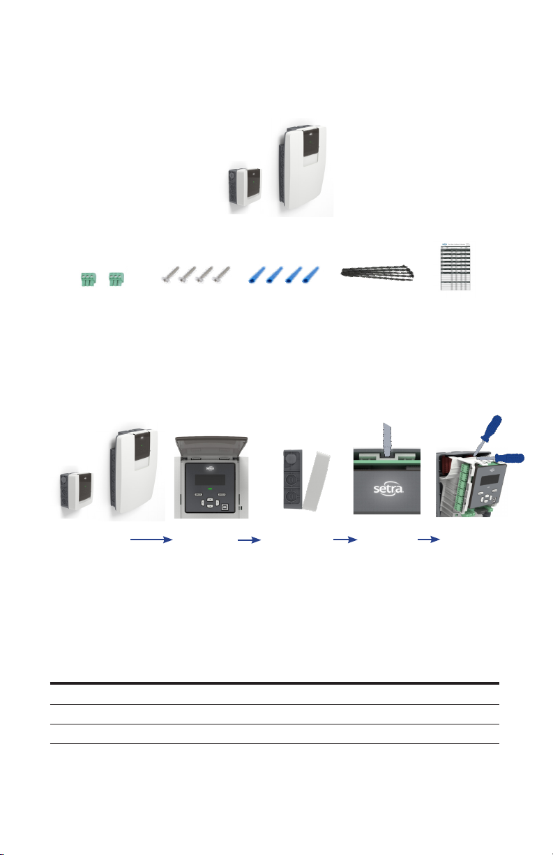
1.5 Product unpacking
What's in the box
CT connector kit
3/12 Load
Remove meter from box
3/12 Load
Mounting screws Wall anchors
48 Load
Preparing for install
48 Load
Flip open dust cover Pull front cover forward
Pull down on tabs
Auxiliary equipment & hardware kit contents
Cable ties
Insert screwdriver
into slot
Cal. Cert.
Pivot screwdriver up to
remove main assemble
Item
Power Meter 1 1 1
CT connector 4 13 49
Hardware kit 1 1 1
1 1 1
P/N: SPM03EDN
Included w/ meter
P/N: SPM12EDN
Included w/ meter
P/N: SPM48EDN
Included w/ meter
10
Page 11
2.0 Safety Information
Read these instructions carefully and look at the equipment to become familiar with the
device before trying to install, operate, service or maintain it. The following special messages
may appear throughout this manual or on the equipment to warn of potential hazards or to
call attention to information that claries or simplies a procedure.
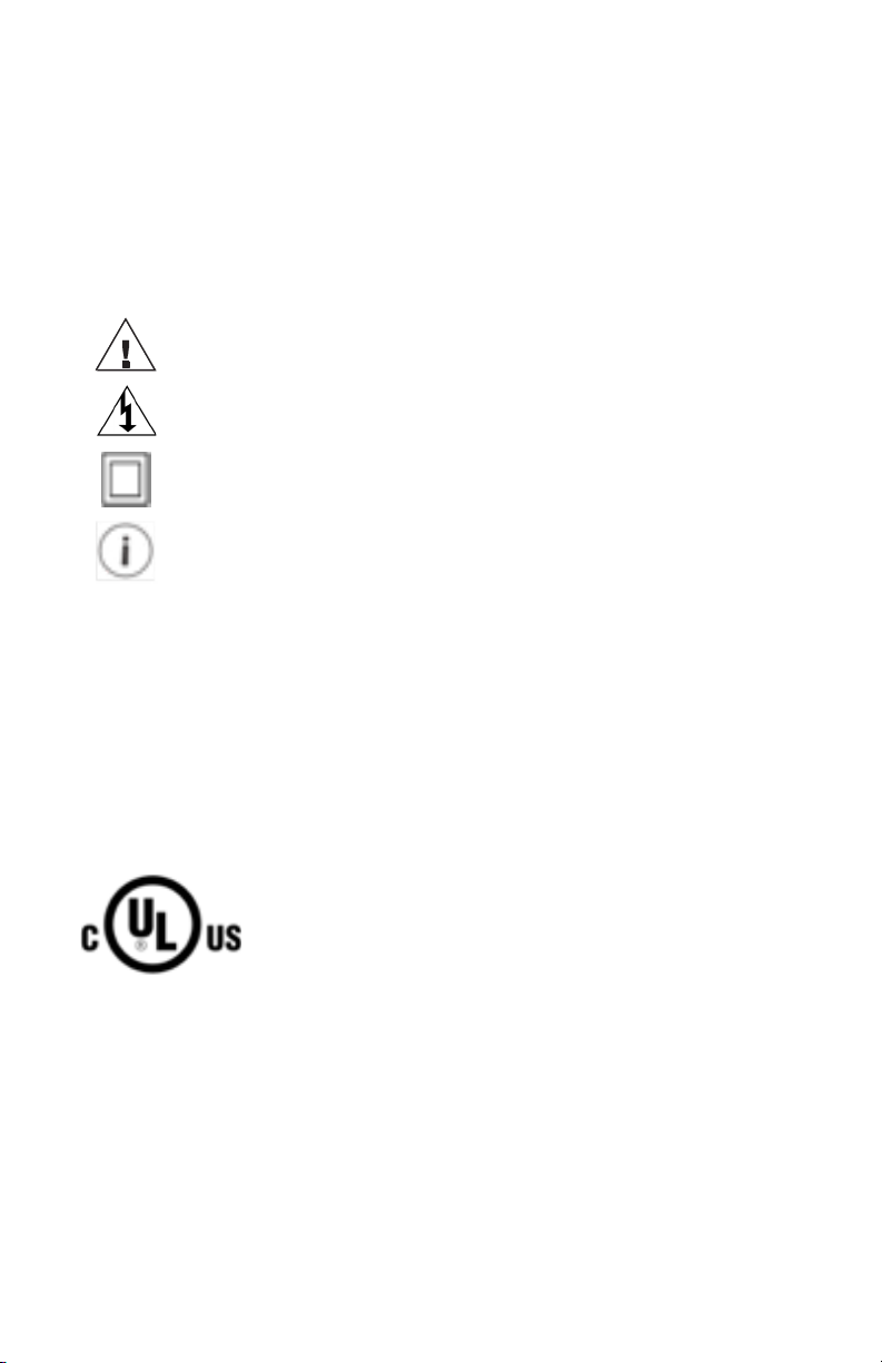
2.1 Safety symbols
The following international symbols are used on the Power Meter and in this manual:
Denotes warning or caution. See manual for a description of the meanings.
DENOTES HIGH VOLTAGE. RISK OF ELECTRICAL SHOCK. LIFE
THREATENING VOLTAGES MAY BE PRESENT. QUALIFIED PERSONNEL ONLY.
Equipment protected throughout by double insulation (IEC 536 Class II)
Contains additional information pertinent to current subject.
2.2 Please note
Electrical equipment should be installed, operated, serviced and maintained only by qualied
personnel. No responsibility is assumed by Setra for any consequences arising out of the
use of this material. A qualied person is one who has skills and knowledge related to the
construction, installation, and operation of electrical equipment and has received safety
training to recognize and avoid the hazards involved.
2.3 Safety approval
The Setra Networked Multi-load Power Meter is UL listed and complies with the following
safety standards for 600V CAT III Pollution Degree 2:
LISTED
E503021
UL 61010-1 Edition 3 (2016),
CSA C22.2 No 61010-1-12 Edition 3 Update 2 (2016),
IEC/EN61010-1 Edition 3 (2013),
Safety Requirements for Electrical Equipment for Measurement, Control and Laboratory Use,
Part 1: General requirements
UL 61010-2-030 Edition 2,
CSA C22.2 No 61010-2-030-12 Edition 1 (2012),
IEC/EN61010-2-030 Edition 1 (2011),
Safety Requirements for Electrical Equipment for Measurement, Control and Laboratory Use,
Part 2-030: Particular Requirements for Testing and Measuring Circuits
11
Page 12
Français
2.0 Informations de sécurité
Lisez attentivement ces instructions et examinez l'équipement pour vous familiariser avec
l'appareil avant d'essayer de l'installer, de le faire fonctionner, de le réparer ou de l'entretenir.
Les messages spéciaux suivants peuvent apparaître dans ce manuel ou sur l'équipement
pour avertir des dangers potentiels ou pour attirer l'attention sur des informations qui clarient
ou simplient une procédure.
2.1 Symboles de sécurité
Les symboles internationaux suivants sont utilisés sur le Power Meter et dans ce manuel:
Indique un avertissement ou une prudence. Voir le manuel pour une
description des signications.
INDIQUE HAUTE TENSION. RISQUE DE CHOC ÉLECTRIQUE. DES TENSIONS
MENACANTES POUR LA VIE PEUVENT ÊTRE PRÉSENTES. PERSONNEL
QUALIFIÉ UNIQUEMENT.
Équipement protégé partout par une double isolation (IEC 536 classe II)
Contient des informations supplémentaires pertinentes au sujet actuel.
2.2 Veuillez noter
L'équipement électrique doit être installé, utilisé, entretenu et entretenu uniquement par
du personnel qualié. Aucune responsabilité est assumée par Setra des conséquences
découlant de l'utilisation de ce matériel. Une personne qualiée est une personne qui
possède des compétences et des connaissances liées à la construction, à l'installation et
au fonctionnement de l'équipement électrique et qui a reçu une formation en sécurité pour
reconnaître et éviter les dangers impliqués.
2.3 Approbation de sécurité
Le Setra Networked Multi-Load Power Meter est UL et conforme aux normes de sécurité
suivantes pour 600V CAT III Degré de pollution 2:
LISTED
E503021
UL 61010-1 Edition 3 (2016),
CSA C22.2 No 61010-1-12 Edition 3 Update 2 (2016),
IEC/EN61010-1 Edition 3 (2013),
Safety Requirements for Electrical Equipment for Measurement, Control and Laboratory Use,
Part 1: General requirements
UL 61010-2-030 Edition 2,
CSA C22.2 No 61010-2-030-12 Edition 1 (2012),
IEC/EN61010-2-030 Edition 1 (2011),
Safety Requirements for Electrical Equipment for Measurement, Control and Laboratory Use,
Part 2-030: Particular Requirements for Testing and Measuring Circuits
12
Page 13

UL Safety Ratings
Equipment function Networked Multi-circuit power meter
Connection to mains supply Permanently
Overvoltage/ Measurement category III
Pollution degree 2
Means of protection Class II (double insulated)
Environmental condition
Temperature:
Humidity:
Altitude:
For use in wet location No
Equipment mobility Wall/surface mounted
Operating conditions Continuous
Marked degree of protection Type 1
Input supply rating: 80-600 Vac (Vin1 L1 & L2), 50/60 Hz, 5W max, Overvoltage Category III
Voltage measurement:
Three phase max. 347/600 Vac WYE earthed
Three phase max. 347 Vac DELTA earthed/unearthed
Split phase max. 240/480 Vac
Single phase max. 480 Vac
Measurement Category III
-20°C to +60°C
5% to 95% non-condensing humidity
Max. 2000 meters
Frequency measurement:
50/60 Hz
Current measurement:
Up to 6000 A (through use of CTs or Rogowski coils with voltage output up to 2V)
Alarm relay output ratings: 30 Vdc/ac, 2 Arms, resistive, Class 2
Pulse I/O: 30 Vdc
13
Page 14

Français
Évaluations de sécurité UL
Fonction d'équipement
Connexion à l'alimentation principale Connecté en permanence
Surtension / Catégorie de mesure III
Degré de pollution 2
Moyens de protection Class II (double isolation)
Conditions environnementales
Température:
Humidité:
Altitude:
Pour une utilisation dans des
endroits humides
Mobilité de l'équipement Montage mural / en surface
Conditions de fonctionnement Continu
Degré de protection marqué Type 1
Capacité d'alimentation d'entrée: 80-600 Vac (Vin1 L1 & L2), 50/60 Hz, 5W max, catégorie
de surtension III
Compteur de puissance multi-circuits
en réseau
-20°C à +60°C
5% à 95% d'humidité sans condensation
Max. 2000 mètres
Non
Mesure de tension:
Triphasé max. 347/600 Vac WYE mis à terre
Triphasé max. 347 Vac DELTA mis à la terre / déterré
Phase divisée max. 240/480 Vac
Monophasé max. 480 Vac
Catégorie de mesure III
Mesure de fréquence:
50/60 Hz
Mesure de courant:
Jusqu'à 6000 A (grâce à l'utilisation de TC ou de bobines Rogowski avec une tension de
sortie jusqu'à 2 V)
Évaluations de sortie de relais d'alarme: 30 Vdc / ac, 2 bras, résistif, classe 2
Puissance d'entrée / sortie d'impulsion: 30 Vdc
14
Page 15

General safety requirements
To ensure the safe operation and service of the device, follow these instructions
closely. Failure to observe warnings can result in severe personal injury or
permanent damage to the device.
• Review the entire manual before use of the Meter and its accessories.
• Comply with local and national safety codes. Use personal protective equipment to
prevent shock and arc flash injury where hazardous live conductors are exposed.
• Only licensed electricians should install this equipment. Such work should be performed
only after reading this entire set of instructions.
• The equipment must be accessible to authorized personnel only. Equipment must be
installed in areas where access can be restricted.
• If the meter appears damaged or defective or internal fuse blowout, rst disconnect all
power to the meter. Then contact Setra technical support for assistance.
• If the products are used in a manner not specied by Setra, the protection provided by
the equipment may be impaired.
Power Meter installation safety requirements
• Use copper conductors only.
• Wiring to voltage input terminals and mains shall have minimal temperature rating of
90°C (194°F) and minimal wire gauge of 14 AWG (1.63 mm).
• External secondary inputs and outputs should be connected to devices meeting the
requirements of IEC 60950.
• For use only with Listed Energy-Monitoring Current Transformers
• Warning - To reduce risk of electric shock, always open or disconnect circuit from powerdistribution system (or service) of building before installing or servicing current-sensing
transformers
• Current transformers may not be installed in equipment where they exceed 75 percent of
the wiring space of any cross-sectional area within the equipment.
• Current transformers may not be installed in an area where they block ventilation
openings.
• Current transformers may not be installed in an area of breaker arc venting.
• Current transformers are not suitable for Class 2 wiring method nor intended for
connection to Class 2 equipment.
• Secure current transformer and route conductors so that they do not directly contact live
terminals or bus.
• Wiring to terminal blocks shall have minimal temperature rating at least 75°C (167°F)
• When connecting power meter to conduit, a threaded hub shall be installed at conduit
entrances. When using rigid conduit connect the hub to the conduit before connecting
to power meter enclosure.
FCC PART 15 Notice
This equipment has been tested and found to comply with the limits for a Class B digital device, pursuant
to part 15 of the FCC Rules. These limits are designed to provide reasonable protection against harmful
interference when the equipment is operated in a commercial environment. This equipment generates, uses,
and can radiate radio frequency energy and, if not installed and used in accordance with the instructions,
may cause harmful interference to radio communications. However, there is no guarantee that interference
will not occur in an installation
15
Page 16

Français
Règles générales de sécurité
Pour garantir le fonctionnement et l'entretien en toute sécurité de l'appareil, suivez
attentivement ces instructions. Le non-respect des avertissements peut entraîner
des blessures graves ou des dommages permanents à l'appareil.
• Revoir le manuel en entier avant l'utilisation de l'appareil et de ses accessoires.
• Respectez les codes de sécurité locaux et nationaux. Utilisez un équipement de protection
individuelle pour éviter les chocs et les arcs électriques lorsque des conducteurs sous tension
dangereux sont exposés.
• Seuls des électriciens agréés doivent installer cet équipement. Un tel travail ne doit être effectué
qu'après avoir lu l'ensemble de ces instructions.
• L'équipement doit être accessible uniquement au personnel autorisé. L'équipement doit être
installé dans des zones où l'accès peut être restreint.
• Si le compteur semble endommagé ou défectueux ou que le fusible a sauté, débranchez d'abord
l'alimentation du compteur. Contactez ensuite le support technique de Setra pour obtenir de l'aide.
• Si les produits sont utilisés d'une manière non spéciée par Setra, la protection fournie par
l'équipement peut être altérée.
Règles de sécurité pour l'installation du Power Meter
• Utilisez uniquement des conducteurs en cuivre.
• Le câblage aux bornes d'entrée de tension et au secteur doit avoir une température nominale
minimale de 90 ° C (194 ° F) et un calibre de l minimal de 14 AWG (1,63 mm).
• Les entrées et sorties secondaires externes doivent être connectées à des appareils répondant
aux exigences de la CEI 60950.
• À utiliser uniquement avec les transformateurs de courant à surveillance d'énergie répertoriés
• Avertissement - Pour réduire le risque de choc électrique, ouvrez ou déconnectez toujours le circuit
du système de distribution électrique (ou du service) du bâtiment avant d'installer ou d'entretenir
des transformateurs de détection de courant
• Les transformateurs de courant ne doivent pas être installés dans l'équipement où ils dépassent
75 pour cent de l'espace de câblage de toute section transversale de l'équipement.
• Les transformateurs de courant ne doivent pas être installés dans une zone où ils bloquent les
ouvertures de ventilation.
• Les transformateurs de courant ne doivent pas être installés dans une zone d'évacuation d'arc du
discontacteur.
• Les transformateurs de courant ne sont pas adaptés à la méthode de câblage de classe 2 ni
destinés à être connectés à un équipement de classe 2.
• afxez le transformateur de courant et circulez les conducteurs an qu'ils n'entrent pas directement
en contact avec les bornes sous tension ou le bus.
• Le câblage aux borniers doit avoir une température nominale minimale d'au moins 75 ° C (167 ° F)
• Lors de la connexion du wattmètre au conduit, un moyeu fileté doit être installé aux entrées
du conduit. Lorsque vous utilisez un conduit rigide, connectez le moyeu au conduit avant de le
connecter au boîtier du wattmètre.
Avis FCC PARTIE 15
Cet équipement a été testé et déclaré conforme aux limites d'un appareil numérique de classe B, conformément
à la partie 15 des règles de la FCC. Ces limites sont conçues pour fournir une protection raisonnable contre les
interférences nuisibles lorsque l'équipement est utilisé dans un environnement commercial. Cet équipement
génère, utilise et peut émettre de l'énergie radiofréquence et, s'il n'est pas installé et utilisé conformément
aux instructions, peut provoquer des interférences nuisibles aux communications radio. Cependant, il n'y a
aucune garantie qu'aucune interférence ne se produira dans une installation.
16
Page 17
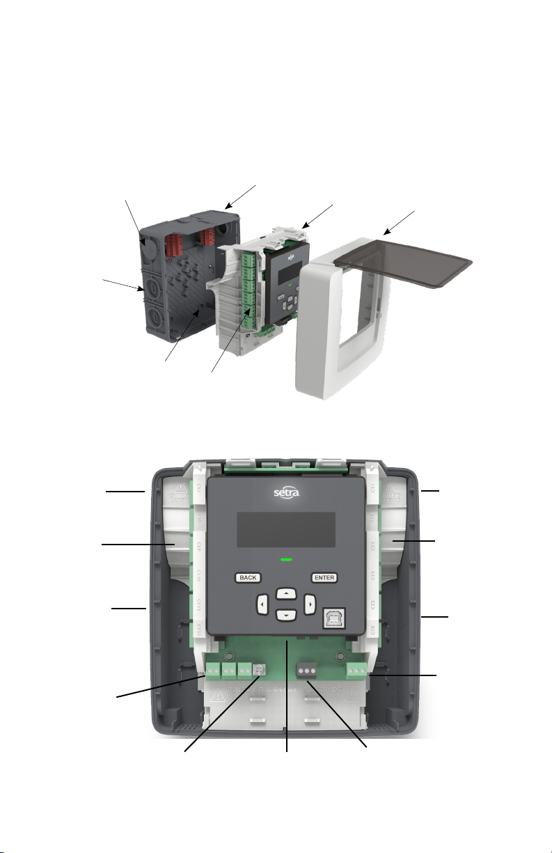
3.0 Meter overview
This section is intended so that you can familiarize yourself with the features of the meter prior
to installation, while size and amount of current transformer connection differ most features
and terminology remain the same between the 3, 12, and 48 load power meters.
Power meter sections
(12 load meter shown)
Conduit plug x2 high
voltage area
Conduit knockout
CT area x4
Back housing
Main assembly
Front housing
Mounting holes (x4)
CT inputs
3/12-load meter
High voltage
conduit entry
CT inputs x6
(12 Load only)
Low voltage
conduit entry
Pulse IO
Input x2
Output x1
Earth ground1
screw terminal
(optional)
1
Earth ground Screw: In noisy environments connect earth ground terminal to electrical panel earth ground to reduce noise
pickup
Ethernet RJ45
connection
EIA-485
communication
terminal
High voltage
conduit entry
CT Inputs
x3 (3 Load meter)
x6 (12 Load meter)
Low voltage
conduit entry
SPDT alarm relay
17
Page 18
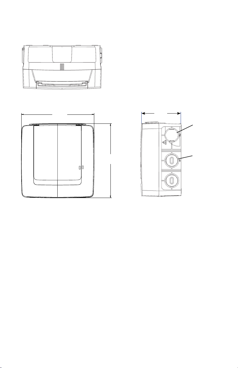
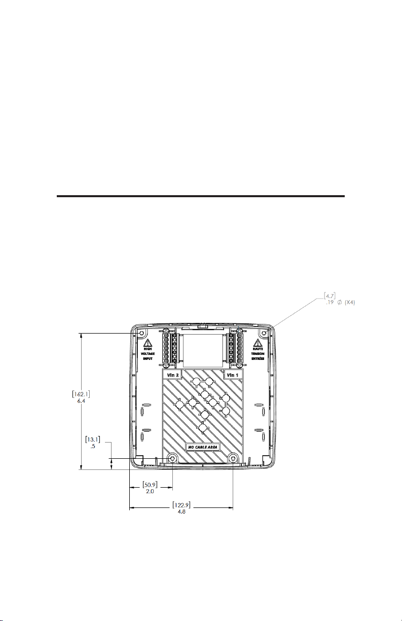
95.9
3.8
Dimensions
6.8
173.9
6.8
[173.9]
3.8
[95.9]
3/4” (Conduit
Opening)
177.1
7.0
7.0
[177.1]
3/4” (Conduit
Opening)
18
Page 19
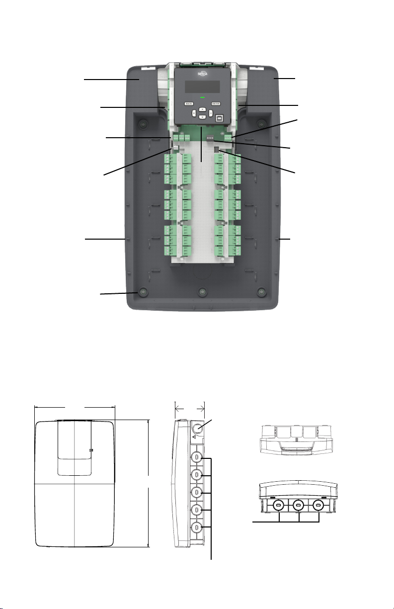
48-Load Meter
112
4.4
435.7
17.2
274.9
10.8
112
4.4
High voltage
conduit entry
CT input x6
Pulse I/O
Input x2
Output x1
Earth ground1
screw terminal
(optional)
Low voltage
conduit entry x5
Mounting hole
x5
Connection
Ethernet RJ45
High voltage
conduit entry
CT input x6
SPDT alarm
relay
EIA-485
Communication
terminal
DIP switches
(EIA-485 Config)
Low voltage
conduit entry
x5
Dimensions
10.8
274.9
10.8
[274.9]
17.2
435.7
17.2
[435.7]
4.4
[112]
1” Conduit Opening
19
3/4”
1” Conduit
Opening
Top view
Bottom view
in.
[mm]
Page 20
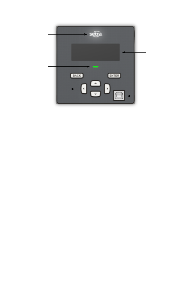
Power indication
LED
Error indication
LED
Simple 6-key
user-interface
Display interface
4-Line backlit
display
Type B port USB
20
Page 21
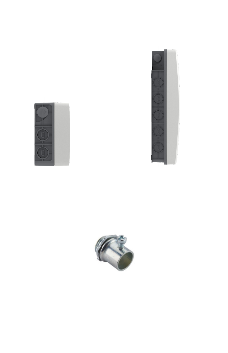
Available conduit
3/12 Load meter 48 Load meter
High voltage area – ¾" EMT conduit tting x2
Low voltage (CT, Comm, I/O) – ¾" EMT conduit tting x4
Typical EMT conduit tting (Not included)
High voltage area – ¾" EMT conduit tting x2
Low voltage (CT, Comm, I/O) – 1" EMT conduit tting x13
21
Page 22
3.1 Installation overview
Vin 1
1. Mount unit in preferred conduit
orientation with provided mounting
screws.
CT
Input
4. Following local electrical codes.
Wire in the current transformers
and communication lines to the
meter.
2. After safely de-energizing the circuit,
properly wire in the lines voltage per
local electrical codes.
L1
5. Install front cover by engaging the
two tabs at the bottom and rotate the
cover until clicked in-place.
3. Install the “Main assembly” into
the back housing until it locks in
place.
6. After meter is fully wired, safely
re-energize the circuit and begin
gathering data.
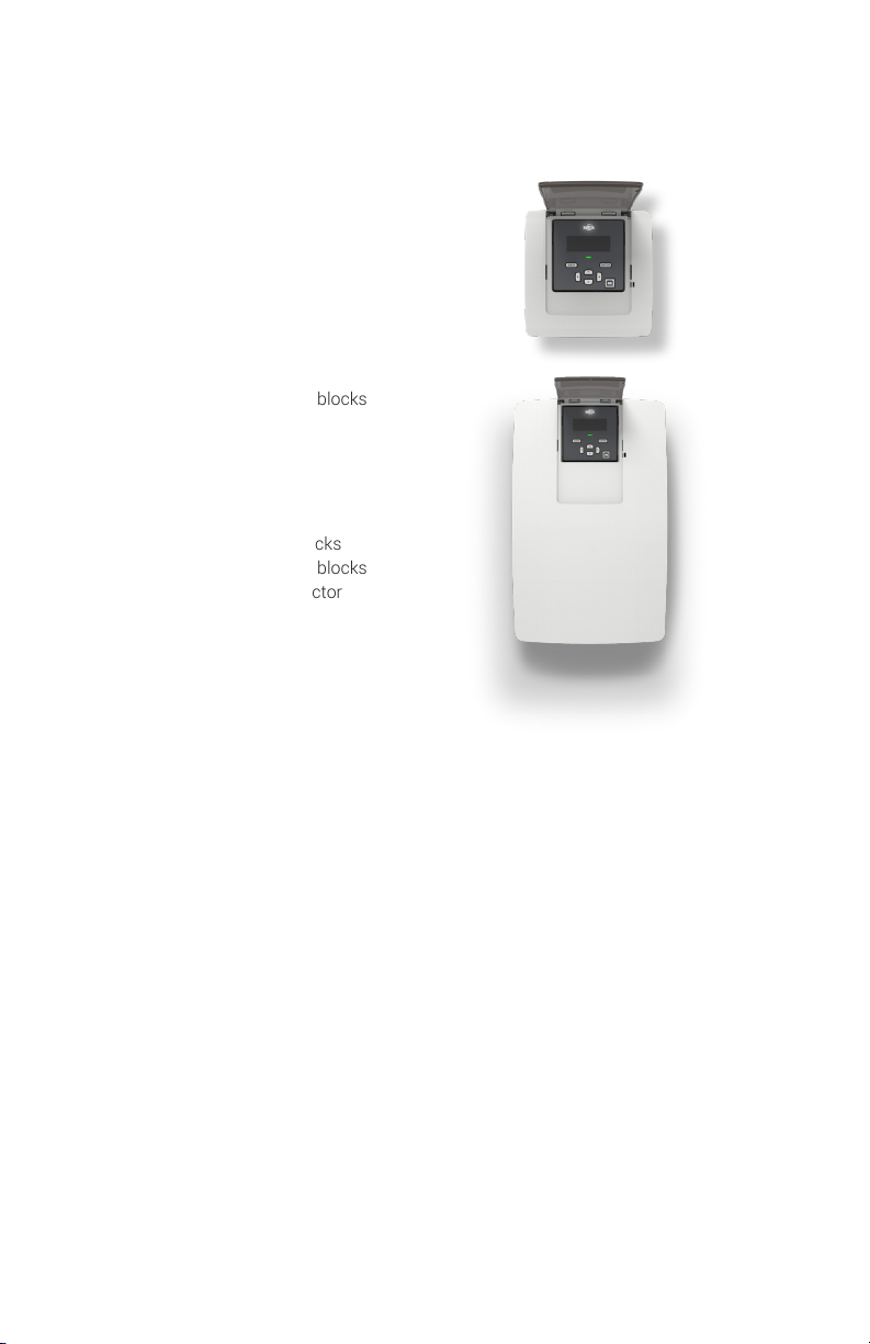
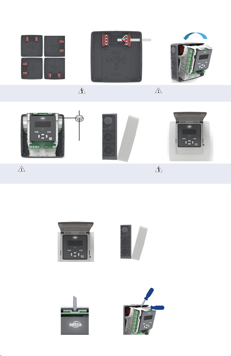
3.2 Main assembly and back housing separation/attachment
1. Remove the power meter’s front housing (cover) by depressing the tab(s) on the bottom
of the meter, found on the main assembly. Simultaneously, lift the front housing off the stillassembled main assembly and back housing.
2. Next, remove the main assembly from back housing by flexing the rear housing away from
the main assembly using a flat screwdriver where indicated on the rear housing. This will
release the locking mechanism. Now, pull delete out the main assembly, rotating from the top.
22
Page 23
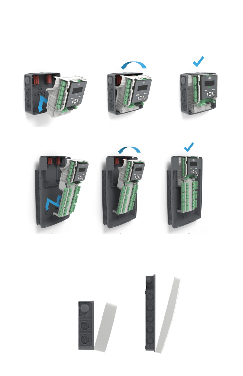
3. To reassemble, rst, insert the bottom of the Main Assembly into the Back Housing and
rotate the top of the main assembly into position, connecting high voltage and accompanied
by a "click" to ensure the assembly is in place.
12 Load Meter shown below:
48 Load Meter shown below:
4. Attach the front housing by tilting the cover such that the bottom makes contact with the
Main Assembly rst, locking in the two securement tabs. Once the tabs are resting in their
respective securement slots, rotate and push the top of the cover onto the Back Housing and
Main assembly.
23
Page 24
4.0 Planning for installation
Meter installation often includes coordination between individuals or groups of people with
different responsibilities. Spend a few minutes considering who will be executing each portion
of the installation and what tools are needed at each stage. Things to consider include
determining how to communicate with the meter, setting address conguration, access to
passwords, etc. The more tasks completed before installation means less time in the eld. The
following section gives an overview of these activities followed by details in the next section.
4.1 Meter conguration overview
Work performed ahead of the installation saves time in the eld and allows
a more streamlined installation. Typically performed at the workstation with
a computer.
Tools Typical work
Desktop or laptop PC Connect USB/Ethernet cable from PC to meter
USB type AB cable (preferred) or
Ethernet cable
Web browser and electrical schematics
of project
4.2 Meter installation overview
Performed by a licensed electrician
Tools Typical work
Mounting hardware (customer supplied) Mechanical mounting
Wiring & supplies, labels, wire ties Electrical installation
Laptop PC Install voltage cover
Multimeter, current clamp Apply power to meter
Camera Conrm basic operation of meter
Establish communication with meter
Firmware update (if desired)
Meter setup and conguration generate eld
wiring and installation report
4.3 Verication & communication overview
Can be modied with power applied to the meter
Tools Typical work
Laptop PC/Tablet, BAS system Conrm device communication
On site troubleshooting Add wire terminations (if required)
Multi meter Conrm and correct wiring issues
Current clamp
Osciloscope (optional) Check signal and noise
BACnet or Modbus polling toll (optional) Network verication
Meter health metrics (check for
setup errors)
24
Page 25
4.4 RTU programming and script overview
Tools Typical work
Laptop PC (remote access to RTU) Conrm meter communication setting
Remote trouble shooting Conrm communication protocols
Register Exercise remote connectivity
Run conguration scripting
Conrm integrity
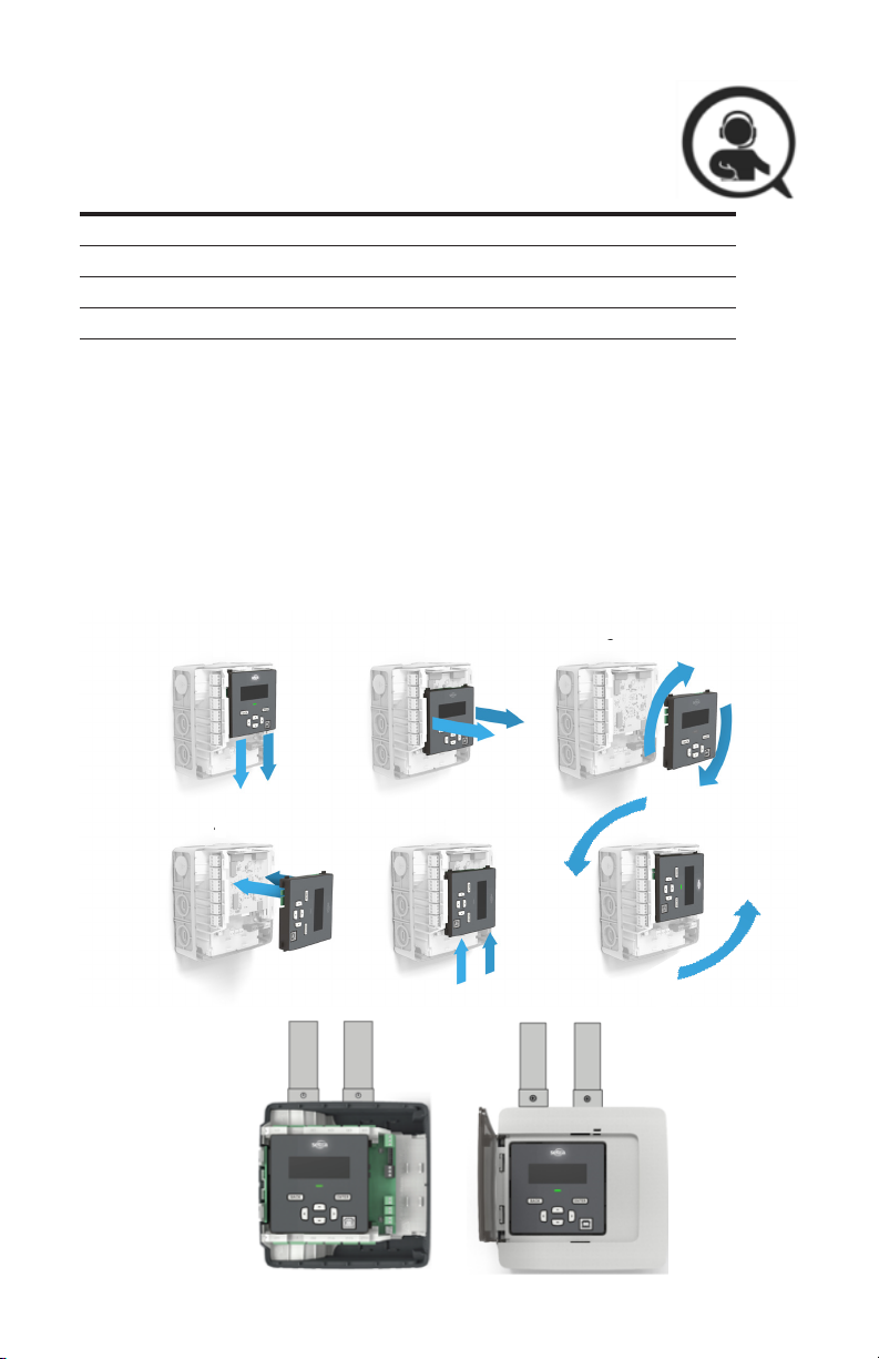
5.0 Changing Conduit Position
The Setra power meter can support various applications via rotatable display to allow the user
to mount in any conguration, without impacting the user interface experience.
To rotate the orientation of the display, remove the front housing cover and slide the display
module along the main assembly, toward the bottom of the meter. Once it becomes dislodged,
simply rotate the display to the desired orientation and slide again toward the top of the meter.
Ensure the meter is de-energized prior to changing orientation.
1 2 3
4 5
25
6
Page 26
6.0 Meter conguration
The following section illustrates the recommended installation of 12-load Power Meter. The
3-load and 48-load meter are slightly different but can follow the same procedure.
1. Remove all packaging material and separate the housing from the other components.
2. Locate a flat, clean portion of wall space for mounting. Decide meter orientation.
3. Remove main assembly for back housing by depressing the tab on the top of the meter, to
release the locking mechanism.
4. Locate, mark, level, and drill wall mounting points. The plastic back cover can be used as
a template for marking the drill locations on the wall. Using the four #8-15 x 5/8 screws
provided, fasten the housing to the wall.
Notes
1
If mounting on masonry wall, use the four blue Topcon screws provided. The
correct masonry drill size for these screws is 5/32 inch diameter
2
If mounting on drywall, use the four plastic drywall anchors in addition to the
#8-15 x 5/8 screws provided.
3
To avoid damage to the housing desired knockouts should be removed prior
to mounting on the wall
26
Page 27

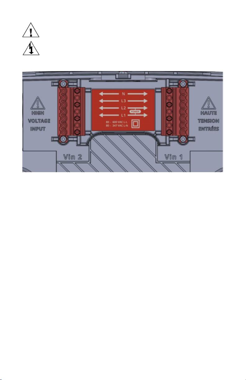
7.0 Connecting high voltage inputs
DANGER- Failure to follow these instructions will result in death or serious injury.
HAZARD OF ELECTRIC SHOCK, EXPLOSION, OR ARC FLASH
• Apply appropriate personal protective equipment (PPE) and follow safe electrical work
practices. See NFPA 70E.
• This equipment must only be installed and serviced by qualied electrical personnel.
• Turn off all power supplying this equipment before working on or inside equipment.
• The meters voltage leads (L1, L2, L3, and N, as necessary) must be connected to a
dedicated disconnect or a properly rated (15A) breaker.
• A voltage lead of 14 AWG THHN minimum 600VAC rating or equivalent is required.
• Wiring to these terminal blocks shall be tightened to 3.54 lb.-in torque.
• DO NOT EXCEED 347V Line to Neutral or 600V line to line. This meter is equipped to
monitor loads up to 347V L-N. Exceeding this voltage will cause damage to the meter
and danger to the user. Always use a Potential Transformer (PT) for voltages in excess of
347V L-N or 600V line to line. The Setra Power Meters are 600V Over Voltage Category
III device.
• When using rigid conduit, connect the hub to the conduit before connecting to power
meter enclosure.
• All unused conduit openings need to be closed using Setra provided conduit plug.
IMPORTANT- Verify the circuit breaker is marked as the disconnected breaker for the meter.
Setra Power Meter’s high voltage inputs must be connected through properly rated (15 Amp)
disconnects or breakers that disconnect all line wires so that they can be powered down. Each
disconnect or breaker must be located within easy reach of the meter operator and must be
labeled to indicate which set of device inputs it supplies power to. One disconnects is required
for each voltage input. The disconnect device or devices must meet IEC 60947-1, IEC 609473 and/or comply with the local electrical code.
Connection to the mains terminals shall be made with 14 AWG (1.63 mm) minimal wire gauge
THHN 600VAC rating. All high voltage input wires shall be routed through the high voltage
conduit entry and do not mix with other low voltage wiring. Any unused high voltage conduit
holes shall be plugged securely with supplied “safety cap”. Wiring to these terminal blocks
shall be tightened to 3.54 lb.-in torque.
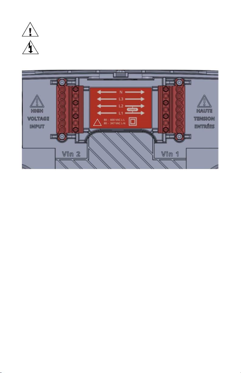
Please note that there are two voltage inputs (Vin1 and Vin2) for 12-load and 48-load power
meter but only one voltage input (Vin1) for 3-load power meter. Each voltage inputs contain
up to four leads, namely L1, L2, L3, and N (neutral) which can be congured by software to
measure up to three phases voltage signal with respect to N (neutral). Vin1 L1 and L2 are also
connected to meter’s 80-600V wide input power supply to power the meter. When installing
a 12 or 48 load power meter, Vin 1 must be used to power the unit. The meter will not power
off of Vin 2.
27
Page 28

Français
7.0 Connexion des entrées haute tension
DANGER- Le non-respect de ces instructions entraînera la mort ou des blessures graves.
RISQUE DE CHOC ÉLECTRIQUE, D'EXPLOSION OU D'ARC ÉLECTRIQUE
• Appliquer d’équipement de protection individuelle (EPI) approprié et suivre les pratiques
de travail électriques sécuritaires. Voir NFPA 70E.
• Cet équipement ne doit être installé et entretenu que par personnel électrique qualié.
• Coupez l'alimentation électrique de cet équipement avant de travailler sur ou à l'intérieur
de l'équipement.
• Les ls de tension des compteurs (L1, L2, L3 et N, si nécessaire) doivent être connectés à
un sectionneur dédié ou à un disjoncteur de calibre approprié (15A).
• Un câble de tension de 14 AWG THHN de 600VAC minimum ou équivalent est requis.
• Le câblage de ces borniers doit être serré à un couple de 3,54 lb-in.
• NE DÉPASSEZ PAS la ligne 347 V au neutre ou la ligne 600 V à la ligne. Ce compteur
est équipé pour surveiller des charges jusqu'à 347V L-N. Le dépassement de cette
tension endommagera le compteur et mettra en danger l'utilisateur. Utilisez toujours un
transformateur de potentiel (PT) pour les tensions supérieures à 347 V L-N ou 600 V ligne
à ligne. Les wattmètres Setra sont des machines de catégorie III de survoltage de 600 V.
• Lorsque vous utilisez un conduit rigide, connectez le moyeu au conduit avant de le
connecter au boîtier du wattmètre.
• Toutes les ouvertures de conduit inutilisées doivent être fermées à l'aide du bouchon de
conduit fourni par Setra.
28
Page 29
DO NOT EXCEED 347V Line to Neutral or 600V line to line. This meter is equipped
to monitor loads up to 347V L-N. Exceeding this voltage will cause damage to
the meter and danger to the user. Always use a Potential Transformer (PT) for
voltages in excess of 347V L-N or 600V line to line. The Setra Power Meters
are 600V Over Voltage Category III device.
29
Page 30
Français
NE DÉPASSEZ PAS la ligne 347 V au neutre ou la ligne 600 V à la ligne. Ce
compteur est équipé pour surveiller des charges jusqu'à 347V L-N. Le
dépassement de cette tension risque d'endommager l'appareil et de danger
pour l'utilisateur. Utilisez toujours un transformateur de potentiel (PT) pour les
tensions supérieures à 347 V L-N ou 600 V ligne à ligne. Les wattmètres Setra
sont des dispositifs de catégorie III de surtension de 600 V
!
30
Page 31

It is important to understand the electrical service type and voltage before voltage input wiring.
Setra power meter supports all major service types.
1. Identify conduit plug(s) to remove for high voltage input. Identify desired conduit holes for
CT and I/O inputs.
2. Power lines can be brought to the meter through any of the top two ports on the housing,
located left side, top, or right side.
3. Once you have identied the convenient routing of conduit to the meter, proceed to step 4
Conduit plug
4. Insert conduit tting through 3/4" opening. Thread nut onto the tting. Tighten until secure.
DO NOT ENERGIZE METER FOR VOLTAGE INPUT WIRING.
SEE SECTION "CONNECTING HIGH VOLTAGE INPUTS" FOR MORE INSTRUCTIONS
31
Page 32

5. Strip back Romex wire sheathing approximately 3-1/2 inches. Strip each wire back
ORIGINAL ARTWORK
- USE FOR REPRODUCTION -
COMPOSITE
ORIGINAL ARTWORK
- USE FOR REPRODUCTION -
DIE LINE
approximately 3/8 inches.
6. Route the power wires beneath the RED power connectors and form the wires using
pliers for easy insertion into the connector according to the owner’s manual wiring
diagram.
WARNING
• Conduit plug – do not allow a pass through to a high voltage area to remain open. Utilize
the provided plugs if conduit is not connected
• Do not route wires around or over the RED connector or allow wires to traverse the safety
“No Cable Area”
7. Upon completion of the wiring, you are ready to insert the Main Assembly. Insert the
two feet of the Main Assembly into the receivers found in the rear housing. Rotating
the Control Board into position, depress the top portion into place, connecting the
two RED power connectors to the Control Board assembly. Correct positioning will be
accompanied by a clicking sound as the assembly becomes locked into place in the
housing.
POWER
32
Figure 6
Page 33

Français
ORIGINAL ARTWORK
- USE FOR REPRODUCTION -
COMPOSITE
ORIGINAL ARTWORK
- USE FOR REPRODUCTION -
DIE LINE
ATTENTION
• Prise Conduit - ne permettent pas de passer à travers une zone à haute tension reste
ouverte. Utiliser les bouchons fournis si le conduit n’est pas connecté
• Ne pas passer les ls autour ou sur le connecteur ROUGE ou permettre des ls de traverser
la sécurité “Non Zone câble ”
POWER
Figure 6
33
Page 34

8.0 Current transformer wiring
Mount conduit ttings and conduits
WARNING
• Conduit grounding – required electrical grounding of the meter through conduit
• EMT tting – EMT tting must comply with all local electrical codes
• Current Transducers may not be installed in a panel where they exceed 75% of the wiring
space of any cross-sectional area within the panel.
• Restrict installation of current transformer in an area where it would block ventilation
openings
• Restrict installation of current transformer in an area of breaker arc venting.
• Not suitable for Class 2 wiring methods
• Not intended for connection to Class 2 equipment
• Secure current transformer and route conductors so that they do not directly contact live
terminals or bus
1. Place tool in the center feature of the molded in knockout
2. Force tool through the knockout
3. Insert conduit tting through knockout
4. Thread nut onto the tting
5. Tighten until secure
34
Page 35

Français
8.0 Câblage du transformateur de courant
ATTENTION
• Mise à la terre conduit – mise à la terre électrique nécessaire du compteur par le conduit
• Montage EMT – raccord EMT doit être conforme à tous les codes locaux
• Transducteurs actuel ne peut pas être installé dans un panneau où ils dépassent 75% de
l'espace de câblage d'une section transversale dans le panneau.
• Restreindre l'installation d'un transformateur de courant dans une zone où il bloquerait les
ouvertures de ventilation
• Restreindre l'installation du transformateur de courant dans une zone de ventilation d'arc
du disjoncteur.
• Ne convient pas aux méthodes de câblage classe 2
• Non destiné à être connecté à un équipement de classe 2
• Fixez le transformateur de courant et acheminez les conducteurs de manière à ce qu'ils
n'entrent pas directement en contact avec les bornes sous tension ou le bus
35
Page 36
WARNING- Failure to follow these instructions may result in safety concern or damage
to meter.
• To reduce the risk of electric shock, always open or disconnect circuit from powerdistribution system (or service) or building before installing or servicing current
transformers.
• The meter shall use Listed Energy-Monitoring Current Transformers
• Setra Power Meter can accept Rogowski Coil and voltage output current transformer up
to 2V rms. Recommended CT rated output is 333 mV (rms). Apply CT output higher than
4Vrms can damage the meter.
• Current Transducers may not be installed in a panel where they exceed 75% of the wiring
space of any cross-sectional area within the panel.
• Wiring to CT terminal blocks shall be tightened to 4.43 lb-in torque.
• All unused conduit opening need to be closed using UL listed conduit plugs.
• When using rogid conduit, connect the hub to the conduit before connecting to power
meter enclosure
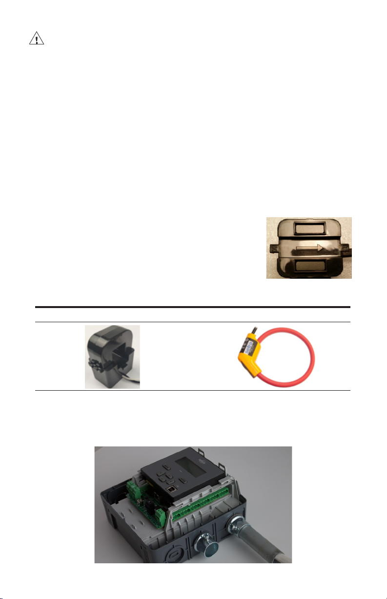
Ensure CT orientation & placement:
• Arrow points toward load (or as instructed by CT label)
• Placed on First Conductor of voltage reference (L1-L2)
circuits are placed on L1
• Observe wiring color and polarity
• Use the Shield wire if provided (connect to PCB terminal
marked S)
Setra CT wiring guide
Split Core CTs Rogowski CTs
White: Positive
Black: Negative
(No shield)
6. Attach Main Assembly to Back Housing, ensuring housing is secure and clicks into place.
Red: Positive
Black: Negative
Bare Wire: Shield
36
Page 37

Français
ATTENTION- LE NON-RESPECT DE CES INSTRUCTIONS PEUT ENTRAÎNER
DES PROBLÈMES DE SÉCURITÉ OU DE DOMMAGES MÈTRES.
• Pour réduire le risque de choc électrique, ouvrez ou déconnectez toujours le circuit du
système de distribution électrique (ou du service) ou du bâtiment avant d'installer ou
d'entretenir les transformateurs de courant.
• Le compteur doit utiliser des transformateurs de courant de surveillance de l'énergie
répertoriés
• Le Power Meter de Setra peut accepter une bobine Rogowski et un transformateur de
courant de sortie de tension jusqu'à 2 V eff. La sortie nominale CT recommandée est de
333 mV (valeur efcace). Appliquer une sortie CT supérieure à 4 Vrms peut endommager
le multimètre.
• Les transducteurs de courant ne doivent pas être installés dans un panneau où ils
dépassent 75% de l'espace de câblage de toute section transversale du panneau.
• Le câblage aux borniers CT doit être serré à un couple de 4,43 lb-in.
• Toutes les ouvertures de conduit inutilisées doivent être fermées à l'aide de bouchons de
conduit approuvés UL.
• Lorsque vous utilisez un conduit rogid, connectez le concentrateur au conduit avant de le
connecter au boîtier du wattmètre
37
Page 38

7. Insert CT wire through the conduit and strip the wire approximately 3/8" (if necessary)
8. Connect the CT wires to the CT connectors provided with your meter in accordance to
the wiring diagram provided by the manufacturer
9. Plug connector into mating connection on the Main Assembly and note the CT location
for conguration.
38
Page 39

9.0 CTs wiring example
The image below is the counterpart to the service panel illustration and indicates how
to connect CTs to Setra Power Meter for each service type. For service types that are not
specically listed, it is recommended to choose “single phase” service and congure each
channel individually. Three phase loads are illustrated on the left and split phase loads on the
right as an example only. CT inputs are fully interchangeable on the meter.
3-Phase
39
Page 40

Single Phase
10.0 EIA-485 communication wiring
Setra meter uses a 2-Wire isolated Half Duplex EIA-485 implementation. It is used for BACnet
MS/TP or Modbus RTU communication. Supported baud rate are 9600, 19200, 38400 (default),
57600, and 76800. 8 data bits, no parity, 1 start, 1 stop bit. Maximum distance is 1000m.
The recommended wiring for EIA485 is 20 AWG or 22 AWG shielded twisted pair wires.
Connect the shield to earth/ ground at one end only. Wiring to terminal blocks shall be
tightened to 1.77 lb-in torque.
• Termination Resistors – are NOT included on 3/12-load meter. If the meter is at the end
of a daisy-chain, then connect a 120-ohm leaded resistor between the + and - terminal
at the RS485 connector. For 48-load meter please use the DIP switch to turn it on or off
accordingly.
• Bias Resistors – are not included on 3/12-load meter. Bias resistors are needed if the
idle conditions of the bus are in an indeterminate logic voltage. Bias resistors are usually
located at the master node and are usually 680 ohms for an EIA-485 netword. For 48load meter please use the DIP switch to turn on or off the pull up/pull down bias resistors
accordingly.
• Network Topology – EIA-485 is designed to be implemented as a daisy chain (series
connections) rather than star or cascade topologies.
• Signal Names – Some EIA-485 devices use the terminology A/B while others use +/-.
Note that A is (-) and B is (+). Many manufacturers incorrectly label the terminals.
• Bus Loading – The meter is a 1/8th unit load allowing up to 256 like devices in parallel.
40
Page 41

Français
10.0 Câblage de communication EIA-485
Le câblage recommandé pour EIA485 est de 20 AWG ou 22 AWG câbles blindés à paire
torsadée. Connectez le blindage à la terre / terre à une seule extrémité. Le câblage aux
borniers doit être serré à un couple de 1,77 lb-po.
41
Page 42

Verication includes conrmation of BOTH the physical interface settings (Serial or
Ethernet) and the protocol (Modbus or BACnet) settings.
11.0 Ethernet communication wiring
Connect Setra Power Meter to a 10/100 Basset 802.3-2002 compliant IP network or device
by connecting a CAT5 Ethernet cable to the RJ45 Ethernet port on the Meter. The Ethernet
supports BACnet/IP and Modbus TCP protocol.
1. Install communication and other I/O as your application requires.
42
Page 43

12.0 Pulse inputs wiring
The recommended wiring is 20 AWG or 22 AWG twisted pair wires. Wiring to terminal
blocks shall be tightened to 1.77 lb-in torque.
Setra meters are equipped with 2 isolated pulse inputs. Pulse counting supports accumulation
of consumption data from any external meter (e.g., gas, water, BTU meter) using a dry contact
(Form A relay) or open collector outputs. The minimal ON-state current is 2mA and maximum
OFF-state current is 0.35mA. The maximum input voltage is 30VDC. The pulse inputs are
compatible with "low speed" meters. The minimal pulse width is 20 mS is both the logic low
and high state and pulse rate is 20 Hz.
12.1 Open collector output
The pulse output is electrically isolated from the meter power supply and requires the user
to connect a voltage source (5-30 VDC), a ground wire (connected to the host ground), and a
pull-up resistor. A 10K resistor is the recommended value. The pull up resistor shall be sized
to limit the current through the isolator to 5 mA.
If the collector is connected directly to a source of voltage, the pulse isolator will
immediately burn out and become non-responsive.
Output connections
13.0 Alarm relay (SPDT) wiring
The recommended wiring is 20 AWG or 22 AWG twisted pair wires. Wiring to terminal
blocks shall be tightened to 1.77 lb-in torque.
Setra meter include a single pole double throw electromechanical relay that can be congured
to trigger under loss of voltage conditions. This feature will alert building systems to a “loss
of phase” condition within 100 mSec of occurrence without being polled. Once triggered this
relay will need to be reset via a register command.
Please note this relay shall only be used for Class 2 limited energy wiring. The maximum
contact rating is 2A and 30VDC/30VAC.
43
Page 44

Français
12.0 Câblage des entrées d'impulsion
Le câblage recommandé est des ls à paire torsadée de 20 AWG ou 22 AWG. Le câblage
aux borniers doit être serré à un couple de 1,77 lb-po.
13.0 Alarm relay (SPDT) wiring
Le câblage recommandé est des ls à paire torsadée de 20 AWG ou 22 AWG. Le câblage
aux borniers doit être serré à un couple de 1,77 lb-po.
Veuillez noter que ce relais ne doit être utilisé que pour le câblage à énergie limitée de
classe 2. La valeur nominale maximale des contacts est de 2A et 30VDC / 30VAC.
44
Page 45

14.0 Installing front cover
1. Install front cover by inserting tabs into bottom of the back housing and rotate until it
clicks.
1. Turn on Power. It will take a couple minutes for the meter to start up. When the meter
is fully powered up, the status LED will show either Green (no error detected) or Red
(conguration or measurement error detected). The backlit LCD will show start up
message.
45
Page 46

15.0 Meter conguration
The Setra Power Meter’s congurability allows each product to accurately measure in each
unique application. Simple conguration can be leveraged on the unit’s main LCD display,
and more detailed conguration is best completed using Meter’s integrated Web Portal setup
software. The Web Portal can be accessed using a USB or Ethernet port.
15.1 LCD user interface for simple conguration
To use the LCD display, the meter must be powered either through USB or the high voltage
inputs. The LCD will light up upon receiving power. This will follow with easy-to-follow prompts
that allow the user to simply step through each screen.
15.2 Web portal for main conguration
The meter’s Web Portal is an intuitive, web based setup guide for the 3, 12, and 48 load meters.
To access the meter, the user will rst need to connect with a PC.
15.3 Connect the Meter
USB Connection (Power & Communications)
The preferred method for conguring the meter from a locally connected computer is through
the USB port which provides power to the meter as well as communications. The USB port of
most computers will be able to provide enough current to power the meter for conguration.
However, it shall not be used to measure electrical parameters without the meter connected
to line voltage (Vin 1).
To check the status of the meter, the user can reference both the LCD display and the LED
light indicator. If the LED is green, the status is clear. If the LED is blinking red, there is an error
– which requires investigation; detailed information can be found in the unit through the LCD
display. If LED remains "green" for extended period of time, the meter is not communicating.
Blinking green = Good
Blinking red = Error
Ethernet Port/RS-485 Port Connection (Communications only)
The meter can also be congured through the Ethernet port. Please note that this connection
is for communication only and will not power the unit.
46
Page 47

15.4 Web portal setup
After enabling a connection with the meter, open a web browser on the connected PC and
enter http://10.10.5.2 (this is the static address of the USB port) to start the Web Portal home
page. The user will be prompted to LOGIN to the Portal with a Pin code, for additional security,
if desired.
Upon login, the web portal software will open with the menu navigation sidebar appearing
along the left side.
15.5 Web portal overview
The web portal is structured into three main sections: the meter communication bar, menu
navigation sidebar, and the conguration/data window. The web portal software will allow the
user to congure the meter for their installation as well as view/access data once the meter
fully installed and collecting data.
Menu navigation sidebar
Meter communication bar
Conguration/ Data window
47
Page 48

15.6 Meter communication bar
The meter communication bar is the 3-button user interface that links the web portal software
to the conguration le on the meter.
Send/store the conguration to the meter
Reload/retrieve the current stored conguration from the meter to the portal
Logs out of the current session of the portal, pin code may be needed to log
back in
15.7 Menu navigation sidebar
The menu navigation sidebar allows the user to navigate through the web portal software.
The sidebar is split into seven sections:
1. Setup
Congure unit defaults, dene voltage input(s),
load setup, CT inputs, communication output,
pulse input(s) & output, alarming, and complete
installation report.
2. Power analysis
Access energy & power details for the congured
loads of the meter including: trending, harmonics,
waveform, and running “odometer” measurement.
3. Event log
Access to previously occurring errors and
conguration changes to the meter setup.
4. Alarm status
Access to current alarm status (including LED and
relay state) and previously triggered alarms
5. System
Update current software version, perform factory
and trend data reset, and reboot the meter.
6. Export conguration
Export or import conguration le for a backup of
the fully congured meter or use to import setup to
another meter being installed with a similar setup &
export conguration report.
7. Help
Access technical documentation for the meter and
contact information for technical assistance.
48
Page 49

16.0 Halo-dot
The Halo-dot is a visual indication to the user of where to click to begin conguration, current
status of a given attribute, or numeric indication of the item selected.
16.1 Conguration indication dot
The conguration indication dot resides on or next to an input or output that can be congured
or grouped together by the web portal. The color of the indication dot changes based on the
state of conguration,while the meaning of the color may change slightly depending on the
menu.
Unused
(Not congured)
Fully
Congured
Partially
Congured
Error in
Conguration
16.2 Halo
When the indication dot is surrounded by a “Halo”, it indicates the input or output is selected
and currently being congured.
Selected
Unused
(Not congured)
Selected
Fully
Congured
Selected
Partially
Congured
Selected
Error in
Conguration
16.3 Numerical indication
When the conguration indication dot–has a number inside the symbol, it reflects either the
input number, output number, or the load assignment based on the conguration menu the
user is in.
1 2 3 4
49
Page 50

17.0 Setup menu
The power meter’s web portal conguration software is intended to intuitively walk the user
through the setup of all the crucial inputs and outputs to gain insights into energy usage,
allowing them to make better energy management decisions and support energy strategy
initiatives.
The setup menu is divided into eight menu areas:
1. General settings
Congure/edit general settings for the device, edit
unit defaults & add site specic information about
installation (optional)
2. Voltage inputs
Congure/edit expected line voltage (voltage
reference) & dene service type (wiring) of the
voltage input(s)
3. Load setup
Dene/edit the relationship between the voltage
input(s) and CT(s) for the electrical load being
measured
4. CT inputs
Congure/edit the CT type, rated current, voltage at
rated current and CT polarity
5. Communication
Congure/edit communications type, protocol
parameters, and dene network settings
6. Pulse IO setup
Dene & congure the (2) pulse inputs & (1) pulse
output on the meter
7. Alarm setup
Congure/edit alarm type, setpoint, deadband, delay,
LED indication, relay trigger for conditions that
require notication
8. Installation report
Generate record of installation with snapshot of live
data in a pdf
50
Page 51

18.0 Setup menu help legend
Throughout the web portal there are icons and coloring to help the user know the state of
the conguration and if further action might be needed. These legends are accessible
by clicking the encircled question mark icon and opening the relevant legend on the page.
Within the setup menu, the legend is below:
If the section has this symbol to the right of title, it requires no further action from
user.
Note: When rst logging into the web portal, the user will see the green checkmark
since the defaults are loading at the time of manufacturing.
If the section has this symbol to the right of title the user is required to click the
Upload to Meter button in the Meter communication bar.
Note: The upload to meter button only appears when there is something to upload.
If the section has this symbol to the right of title, it serves as a warning that there may
or may not be more work to do to fully congure the meter.
Note: This will not prevent you from uploading the conguration to the meter,
(warning only).
If the section has this symbol to the right of title, the conguration has a fundamental
error and cannot be uploaded to the meter.
51
Page 52

19.0 General settings
The General Settings menu is where the user can nd general device information, set unit
default parameters, and enter any detailed information about the site where the meter is being
installed. The general settings conguration/data window can be accessed by clicking the
Setup section (if minimized) and then clicking the General Settings menu.
Once in the General settings menu, the user can access three sub menus: Device general, Unit
defaults, and Site information.
19.1 Device general
Within the Device general section, the Product, Model, and Serial no. will automatically be
pulled from the stored values on the meter. The date and time can be set following the
procedures below.
The date can be set by:
1. Click the calender icon
2. Use the left & right arrow to scroll to the correct month/year
3. Click the correct day within the month
4. Click out of the window and your date should be changed
5. To upload changes to the meter, click Upload to Meter in the
communication bar
The time can be set by:
6. Click the clock icon
7. With the hour highlighted in white, click the number that
needs to be set
8. With the Minute highlighted in white, click the number that
needs to be set
9. Click out of the window and your time should be changed
10. To upload changes to the meter, click Upload to Meter in the
communication bar
Note: The date & time set will be used for time stamping during
data collection. The unit will not adjust for daylight savings
time.
52
Page 53
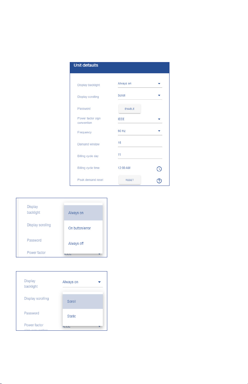
19.2 Unit defaults
Within the Unit defaults section, the user can change global settings that will apply to all
measurements and/or operation of the power meter. Within the Unit defaults menu, the
user can edit: Display backlight, Display scrolling, Password enablement, Power factor sign
convention, frequency, and demand window.
Display backlight
This setting changes the backlight behavior on the physical meter
1. Click the drop down arrow
2. Select Always on (stays on all the time), On
button/error (display will be backlit after a
button press or if there is an error, or always off
(back light is never on)
3. To upload changes to the meter, click Upload to
Meter in the communication bar if conguration
is complete
Display scrolling
This setting changes the behavior of the data on LCD screen
1. Click the drop down arrow
2. Select scroll (real-time data will scroll from load
to load), or Static (real-time data will remain
static until user clicks left/right arrow)
3. To upload changes to the meter, click Upload to
Meter in the communication bar if conguration
is complete
53
Page 54

Password/Pin code
This setting enables/disables pin code access to the mete
1. Click Enabled or Disables
2. Type 4 digit pin code
3. Conrm 4 digit pin code
4. Click save
5. To upload changes to the meter, click Upload to
Meter in the communication bar if conguration
is complete
6. Unit will go to login screen. Enter pin and circle
login button.
Note: Some version of the software require a pin
code. Disabling is not an option.
Power factor sign convention
This setting changes the convention for the power factor sign
1. Click the drop down arrow
2. Select IEC or IEE
3. To upload changes to the meter, click Upload to
Meter in the communication bar if conguration
is complete
Frequency
This setting changes the frequency setting, based on region
1. Click the drop down arrow
2. Select 50 or 60 Hz
3. To upload changes to the meter, click Upload to
Meter in the communication bar if conguration
is complete
54
Page 55

Demand window
This setting changes the time interval for peak demand window
1. Click into the eld
2. Enter desired time interval (1 to 120 minutes)
3. To upload changes to the meter, click Upload to
Meter in the communication bar if conguration
is complete
Billing cycle day
This setting changes day of the month, the peak demand value
in the meter is reset, and is also used to see the last month date
window in the odometer
1. Click into the Billing Cycle day eld
2. Enter day of the month for the peak demand
and odometer the user wants the change
to occur (i.e. if the user enters a value, every
th
11
day of the month the peak demand and
odometer would reset)
3. To upload changes to the meter, click Upload to
Meter in the communication bar if conguration
is complete
55
Page 56

Billing cycle time
This setting changes time of day on the billing cycle day the peak
value in the meter is reset and is also used to set the last month
date window in the odometer
1. Click on the clock symbol to the right of the
current time setting
2. Select new time for reset to occur
3. Click into the grayed out area, new time will
show in the billing cycle time eld
4. To upload changes to the meter, click Upload to
Meter in the communication bar if conguration
is complete
Note: The unit will not adjust for daylight savings
time
Peak demand reset
The peak demand is reset automatically every month on the day
and time as congured in the billing cycle. Pressing the 'Reset'
button resets the peak demand directly once.
1. Click Reset
2. Click OK or CANCEL to continue/not continue
with reset of the current peak demand value
56
Page 57
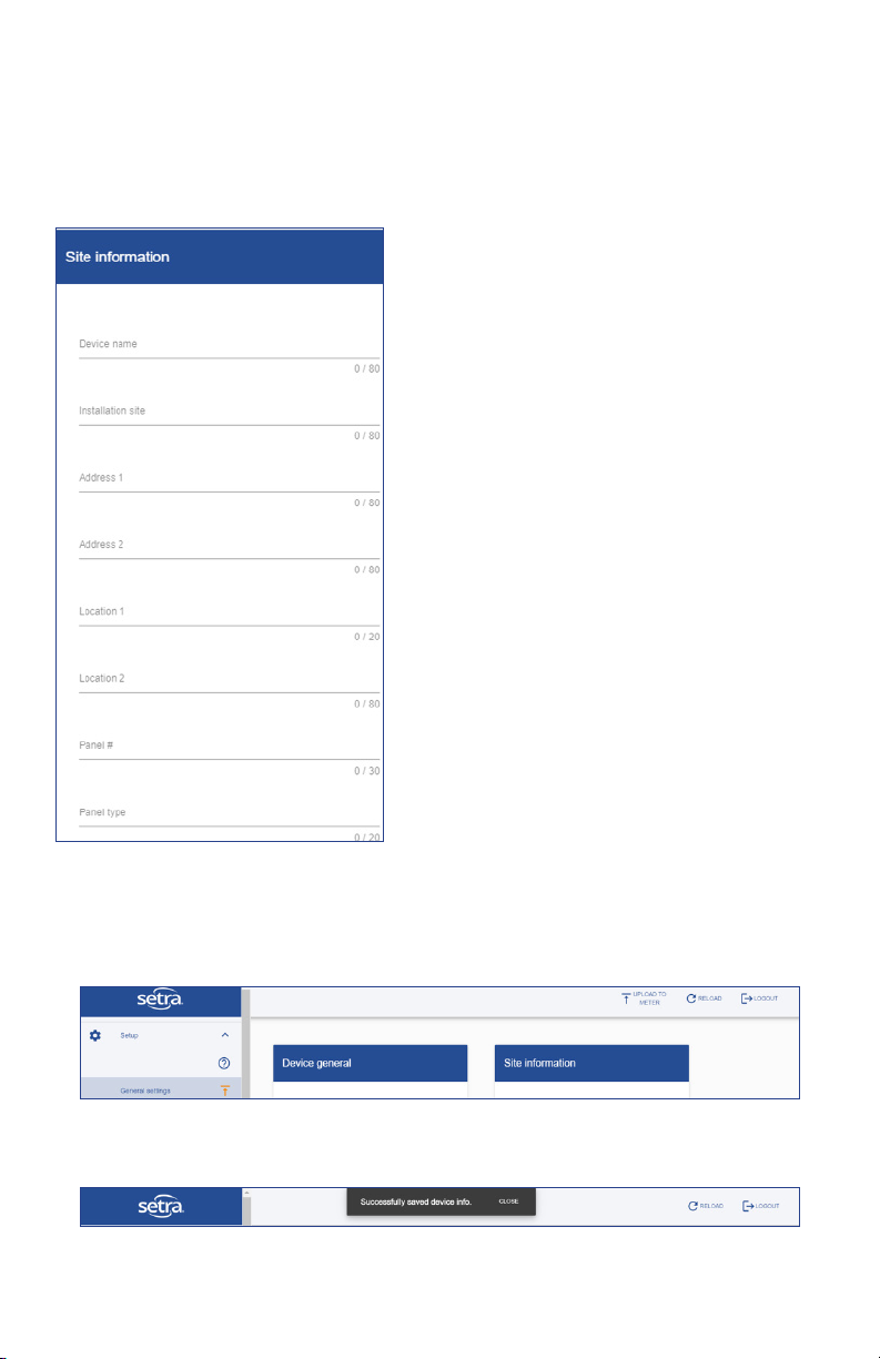
19.3 Site information
The Site information section allows the user to store pertinent information about the job site
directly on the meter. While optional, this information gives the user detailed information
about the site that can be accessed through BACnet, transferred directly to the installation
report, and stored in a job le.
Site information
This is a repository for pertinent job sire information
1. User lls out elds that are pertinent to the job
Note: Each eld has a character limit that is noted
in grey.
19.4 Uploading to meter
With the General settings menu complete, the user can click Upload to meter to load settings
and information on to the meter.
Once the user sees the "Successfully saved device info" flag, the upload is complete, and
changes have been saved.
57
Page 58

20.0 Voltage inputs
The Voltage inputs menu is where the user enters the expected voltage, reads the actual
voltage (if unit is line powered), congures the service type (wiring), and corrects the service
wiring electronically.
To begin setting up the Voltage inputs, click one of the grey conguration dots next to the
Voltage input connector that needs to be congured. The example below shows Voltage input
1 (Vin 1) being selected on a 12 Load meter.
1. Enter the expected voltage for the input; this
can be used for reference and for an alarm
setpoint
2. Select Service type from the drop down list,
wiring diagrams can be accessed by clicking
the help icon
58
Page 59

Service wiring correction
Voltage input conguration
1. Click Save
Note: The "Halo-dot" may turn amber until the input
is assigned to a load.
Voltage input conguration, service wiring
correction
To correct any eld wiring issue the wiring can be changed
electronically be re-assigning the inputs
1. Click the slide switch to enable feature
2. Click drop down
3. Align L1 voltage wire from the panel with the
correct input terminal on the voltage input
connector
4. Click save
59
Page 60

Clear conguration of Voltage input
1. Click Defaults in the lower right of the
conguration window to clear values
2. Values will clear, click SAVE
3. Warning message appears, alerting the user
that all loads associated with the input will be
removed, if ok, click OK
60
Page 61

Voltage input returns to grey, unused state per legend
Halo-dot Legend: Voltage input
61
Page 62

21.0 Load setup
The Load setup menu is where the user denes the relationship between the voltage input and
the CT(s) for the electrical load to be measured.
What is a Load?
A Load is a grouping of a voltage input and current transformer(s) that provides meaningful
energy and power consumption data. A Load can be a voltage reference and (1), (2), or (3)
CT(s) based on your wiring service type and whether it is a single, dual, or three-phase service.
The key feature of the Load setup menu is the flexibility given to the user to mix and match
any combination of single, dual, or three-phase loads within the limit of the Load meter order
(3, 12, or 48).
The Load setup menu is designed to let the user easily congure Loads into meaningful
groupings to support an energy management strategy. Within the Load Conguration window,
the user assigns a Load name, voltage input, and which CT(s) reference which line input based
on the service type ( i.e. L1,L2, or L3).
62
Page 63

21.1 Conguring a Load
Load conguration
1. Click ADD LOAD
2. Type in name for Load
3. Select voltage input; Vin1 or Vin2 (3-load
meter only has Vin1)
4. Select CT that ties into L1 for single phase,
L1 & L2, for dual phase, and L1, L2, & L3 for
three-phase
5. Click save
6. Continue conguring Loads until all CT inputs
are full or all loads being measured by the
meter are congured (See example below)
Note: The number of CTs needed is determined
by congured service type on the selected
voltage input.
If unit is congured to run on a BACnet network,
each load will need a unique virtual device
instance (VDI) assigned to it.
Edit a congured Load
1. Click on the pencil icon to the right of the Load
in the Actions column
2. Make change in voltage input or CT
3. Click save
Delete a congured Load
1. Click on the trash can icon to the right of the
Load in the Actions column
2. Conrm deletion of Load by clicking ok
Note: After changes have been made and saved
the information needs to be uploaded to the
meter to take affect.
63
Page 64

21.2 Visual load indication
To the right of the table is an image of the power meter. Next to each CT input there is a
colored indication dot. Once a Load is dened, a number will appear inside of the indication
dot. The number corresponds to Load number in the table.
Note: CTs do not need to be consecutive to be grouped into a Load.
Halo-dot Legend: Voltage input
64
Page 65
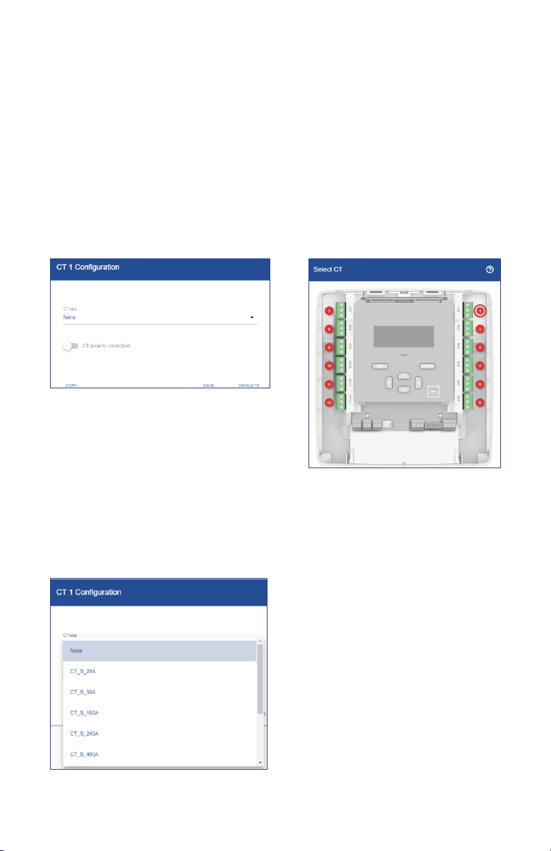
22.0 CT Inputs
The CT inputs menu is where the user goes to dene which CT will be wired into each terminal
block of the power meter. The conguration software has been pre-loaded with congurations
for both Setra’s split core CTs and Patrol Flex Rogowski coils. The user can also congure a
user dened CT, provided the max rating is less than 2V.
Note: 5A CTs cannot be used with the power meter.
To begin setting up the CT inputs, click one of the indication dots near the terminal block
until the “Halo” appears and the heading of the conguration table matches the selected CT
terminal block to be congured. The example below shows Current Transformer input 1 (CT1)
being selected on a 12 Load meter.
Congure CT Input
Congure a CT Input
After clicking on the indication dot next to the CT terminal
block as shown above:
1. Click drop down arrow under CT type
2. Scroll until you nd the part number of the
Setra CT or select user dened
65
Page 66

3. If a Setra CT is selected, Click SAVE, and
conguration is complete. If user dened is
chosen, continue to step 4
4. Type in rated current of the CT congured
Note: Amerage range for user dened must be
between 10 to 10,000 Amps
5. Type in the mV Output at the rated current
6. Click SAVE
Note: Non Setra rogowski coils are not
compatible with the power meter
66
Page 67

Copy a CT conguration
1. Click the indication dot of the CT input that
needs to be copied
2. Click copy in the lower left corner of the
conguration window
3. Click the drop down to select the CT of CTs
the conguration to.
67
Page 68

4. Select the CT or CTs to copy the
conguration to
5. Once all are selected, click OK
6. Review list of CTs that are selected, if
needed click the "X" next to the CT number
to remove it from list
5. Click SAVE
All CTs that were copied to should be either
green or amber based on the state of the
conguration process.
Note: After CT's have been congured the
information needs to be uploaded to the meter.
68
Page 69

Clear conguration of CT input
1. Click indication dot until "Halo" appears
around the CT input you want to clear
2. Click Defaults in the lower right of the
conguration window to clear values
3. Values will clear, click SAVE
69
Page 70

Halo-dot Legend: CT input
The indication dot will change color per the
Halo-dot legend to reflect to reflect state
70
Page 71

23.0 Communications/ Network settings
The communications menu is where the user denes the communications protocol and
network settings for the power meter. The power meter comes standard with 4 advanced
protocol options to t the installation requirements: BACnet MSTP, BACnet IP, Modbus RTU,
and Modbus TCP.
To begin conguration of the communications protocol:
1. Click drop down arrow under
communications type
2. Select protocol to match your building
automation system or energy software
platform
Note: Information needed will change based
on the protocol selected. Continue reading
below for more details on each protocol.
BACnet IP
3. Fill out each attribute in the setup menu
shown to the left
Field Limits are below:
Base Device Instance: 0 – 4194328
Base Device Name: 80 Characters
Virtual Network #: 1 – 65534
UDP Port: 1 – 65534
BBMD address: valid address
BBMD TTL: 1 – 28800
Note: Click BACnet object link for full list.
When BACnet is selected as the communication
protocol, a virtual device instance (VDI) is
assigned to each congured load. The user
must go back and assign a unique VDI to each
congured load to ensure reliable network
performance.
71
Page 72

BACnet MS/TP
3. Fill out each attribute in the setup menu
shown to the left
Field Limits are below:
Base Device Instance: 0 – 4194328
Base Device Name: 80 Characters
Virtual Network #: 1 – 65534
Baud Rate: Selectable 9600, 19200, 38400,
57600, or 76800
MAC Address: 0 – 127
Max Master: (MAC Address + 1) – 127
Max info Frames: 1 - 100
Note: Click BACnet object link for full list.
When BACnet is selected as the communication
protocol, a virtual device instance (VDI) is
assigned to each congured load. The user
must go back and assign a unique VDI to each
congured load to ensure reliable network
performance.
Modbus TCP
Modbus RTU
3. Fill out each attribute in the setup menu
shown to the left
Field Limits are below:
TCP port: 1–65534
Note: Click Modbus Register link for full list.
3. Fill out each attribute in the setup menu
shown to the left
Field Limits are below:
Baud Rate: Selectable 9600, 19200, 38400,
57600, 76800, or 115200
Node Address: 1 - 247
Note: Click Modbus Register link for full list.
72
Page 73
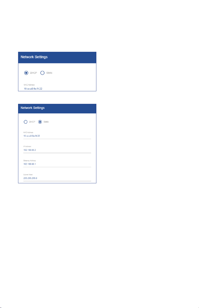
23.1 Network Settings
In the network settings window, the user can congure the IP Address. The power meter’s IP
Address supports either addresses obtained via Dynamic Host Control Protocol (DHCP) or
static IP addresses.
DHCP
If the DHCP server is active on the IP network,
then it will automatically assign an IP address
to the Power Meter
Static
The user can assign a static IP address by
selecting the Static radio button and lling out
the desired MAC address, IP address, Gateway
address, & Subnet mask.
73
Page 74

24.0 Pulse IO setup
The power meter comes standard with (2) pulse inputs and (1) pulse output. The Pulse IO
setup menu is where the user goes to enable/dene either inputs from an external meter or to
enable/dene the pulse output from the power meter.
To begin conguration, click the indication dot above either the pulse input or output
connection to the meter as shown below. Once the “Halo” appears around the indication
dot the header for the input/output conguration window will change to match the selection.
Pulse In
The (2) pulse inputs can be congured to accept a pulse input from several types of meters
including Electrical, Water, Gas, Steam, BTU/Energy, or used as an Event counter.
To begin conguration:
1. Click slide bar to enable input
2. Click drop down to select pulse type
3. Click drop down to select unit of measure
4. Type in the Scaler; value of each pulse in
UOM
5. Click SAVE, Indication dot will become
green
74
Page 75

24.1 Pulse Output
The (1) pulse output can be congured to send out a dened pulse to an external pulse
counting source.
To begin conguration
1. Click the grey indication dot above the
pulse output terminal block (O1), halo will
surround dot
2. Click slide bar to enable output
3. Select a congured load from the drop
down
4. Click drop down to select unit of measure
75
Page 76

5. Enter in the Scaler; value of each pulse in
UOM
6. Enter pulse width (ms)
7. Click SAVE, indication dot will become
green
76
Page 77

Clear conguration of pulse IO
1. Click indication dot until “Halo” appears
around the Pulse input or output you want
to clear
2. Click Defaults in the lower right of the
conguration window to clear values
3. Values will clear, click SAVE
77
Page 78

Halo-dot Legend: Pulse IO setup
The indication dot will change color per the
Halo-dot legend to reflect state.
78
Page 79

25.0 Alarm setup
The Alarm setup menu is designed to let the user easily congure alarms and present the
alarms to the user in simple dened list. Alarms can be congured to trigger a Relay, show
a warning LED and create warning logs for undesirable conditions. An alarm has up to 7
properties that can be congured:
Error Type
The type of the error to look out for. There are 16 types that can be congured, namely:
'Over Power', 'Under Power', 'Energy Usage (Vin)', 'Energy Usage (Load)', 'Polarity CT', 'Under
Voltage', 'Under Current CT', 'Over Current CT', 'Phase Loss CT', 'Undersized CT', 'Excessive
Voltage', 'Excessive Current', 'Peak Demand (Meter)', 'Peak Demand (Vin)', 'Peak Demand
(Load)' and 'Low Power Factor'.
Vin / Line / Load / CT
Depending on the alarm type you can congure either a Voltage input (Vin), Line, Load or CT.
Alarm Set Point
At what value the alarm should be triggered.
Deadband
In what range an alarm-warning should be logged even though the alarm has not yet been
triggered. For example, when conguring 'Over Power' on a load with a Set Point of 1000kW the
alarm will be triggered when the load uses 1000kW. When a Deadband of 50kW is congured
a warning will be logged when the load uses 950kW. A warning will only result in a log entry
and will never trigger the LED or Relay. A dead band of "ø" means no warning is generated.
Delay Seconds
How long the error-condition should exist before the alarm is triggered. This is helpful to
prevent nuisance alarms.
LED Indication
Whether to trigger the Led when the alarm is active.
Relay Trigger
Whether to trigger the Relay when the alarm is active.
To complete an alarm setup the user must click ADD ALARM in the upper right hand corner,
select the error type from the dropdown list and ll out all pertinent information needed for the
selected error type. When alarm condition is fully dened, click SAVE. To restart the alarm
denition, click CANCEL.
79
Page 80
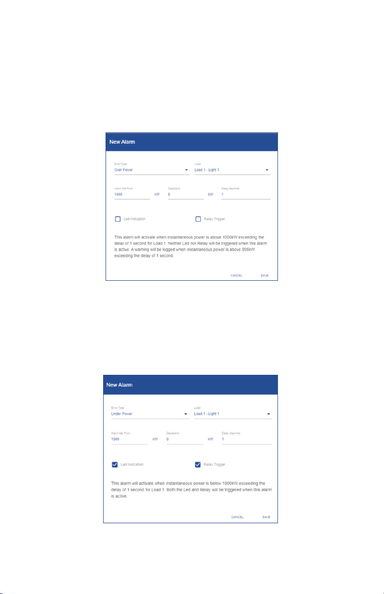
25.1 Congurable Alarms
Over Power
This alarm will activate when instantaneous power is above a kW setpoint exceeding
the alarm delay of delay setpoint in second (s) for a dened load. The user can
congure the LED and/or the alarm relay to be triggered when conditions of the
alarm are met (active). The user can congure a deadband (warning) and alarm
delay for the alarm condition to prevent nuisance alarming in the application.
Example:
Under Power
This alarm will activate when instantaneous power is below a kW setpoint exceeding
the alarm delay of delay setpoint in second (s) for a dened load. The user can
congure the LED and/or the alarm relay to be triggered when conditions of the
alarm are met (active). The user can congure a deadband (warning) and alarm
delay for the alarm condition to prevent nuisance alarming in the application.
Example:
80
Page 81

25.2 Energy usage (Vin)
This alarm will activate when energy consumption for selected voltage input (Vin)
exceeds a kWh setpoint. The user can congure the LED and/or the alarm relay to
be triggered when conditions of the alarm are met (active). This includes energy
consumption for all loads with the selected voltage input (Vin).
Example:
25.3 Energy Usage (Load)
This alarm will activate when energy consumption for selected Load exceeds a kWh
setpoint. The user can congure the LED and/or the alarm relay to be triggered
when conditions of the alarm are met (active).
Example:
81
Page 82
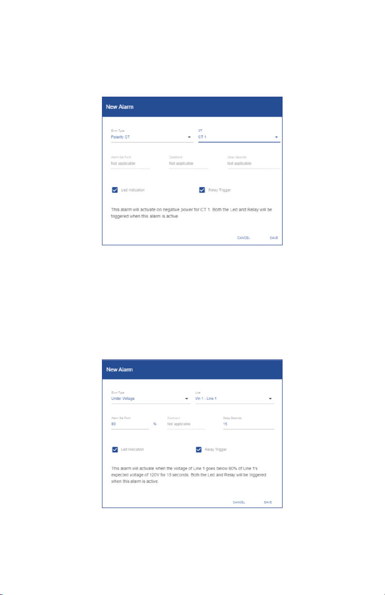
25.4 Polarity CT
This alarm will activate on negative power calculation caused by mis wired CT. The
user can congure the LED and/or the alarm relay to be triggered when conditions
of the alarm are met (active).
Example:
25.5 Under voltage
This alarm will activate when the voltage of selected Line goes below the setpoint
percentage of the Line's expected voltage for more than the entered delay. The user
can congure the LED and/or the alarm relay to be triggered when conditions of the
alarm are met (active). Care must be taken to dene the expected voltages level in
the voltage setup page.
Example:
82
Page 83

25.6 Under current CT
This alarm will activate when the current flow is equal or less than the setpoint for
the selected CT for more than the entered delay. The user can congure the LED
and/or the alarm relay to be triggered when conditions of the alarm are met (active).
Example:
25.7 Over current CT
This alarm will activate when the current flow is equal or more than the setpoint for
the selected CT for more than the entered delay. The user can congure the LED
and/or the alarm relay to be triggered when conditions of the alarm are met (active).
Example:
83
Page 84

25.8 Phase loss CT
This alarm will activate when the difference of load is higher than entered setpoint
percentage for longer than the entered delay. Alarm will be set when ((MaxCurrent
of CT’s that make up a load) minus (MinimumCurrent of CT’s that make up a load))
are divided by the (MaxCurrent of the CT’s that make up a load) are greater than
setpoint percentage. The user can congure the LED and/or the alarm relay to be
triggered when conditions of the alarm are met (active).
Example:
25.9 Undersized CT
This alarm will activate when selected CT is pegged at its max rated current of the
CT for 120 seconds. The user can congure the LED and/or the alarm relay to be
triggered when conditions of the alarm are met (active).
Example:
84
Page 85

25.11 Excessive voltage
This alarm will activate when the voltage of selected Line goes above entered
percentage of the selected Line’s expected voltage (value from voltage input
conguration) for entered amount of time. The user can congure the LED and/or
the alarm relay to be triggered when conditions of the alarm are met (active). Care
must be taken to dene the expected voltage level in the voltage setup page.
Example:
25.12 Excessive current
This alarm will activate when the current exceeds a set amperage for an entered
time for a selected load. The user can congure the LED and/or the alarm relay to
be triggered when conditions of the alarm are met (active).
Example:
85
Page 86

25.13 Peak demand (meter)
This alarm will activate when the sum of all congured loads exceeds an entered
setpoint. The user can congure the LED and/or the alarm relay to be triggered
when conditions of the alarm are met (active).
Example:
86
Page 87
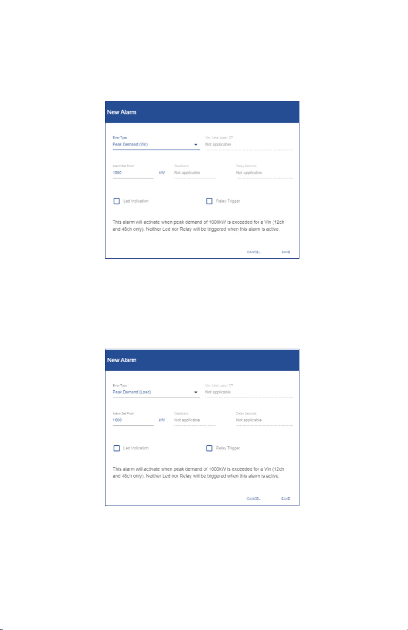
25.14 Peak demand (Vin)
This alarm will activate when the sum of all congured loads referencing a specic
Vin exceeds an entered setpoint. The user can congure the LED and/or the alarm
relay to be triggered when conditions of the alarm are met (active).
Example:
25.15 Peak demand (Load)
This alarm will activate when a selected Load exceeds an entered setpoint. The
user can congure the LED and/or the alarm relay to be triggered when conditions
of the alarm are met (active).
Example:
87
Page 88
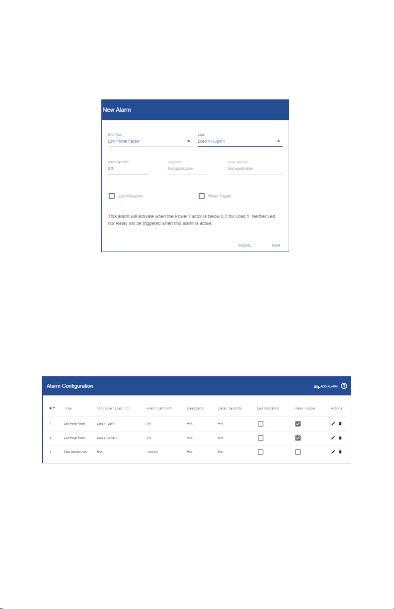
25.16 Low power factor
This alarm will activate when the Power factor is below an entered setpoint for a
selected Load. The user can congure the LED and/or the alarm relay to be triggered
when conditions of the alarm are met (active).
Example:
25.17 Summary alarm table
As each new alarm is created and saved to the meter, the summary table continues
to build as each alarm is added. Alarms that are saved can be edited by clicking the
pencil icon to the right of the alarm. Alarms can also be deleted by clicking the trash
can icon to the right of the congured alarm.
Example:
88
Page 89

26.0 Installation report
The Installation report menu is designed to let the user easily create a document
of record of a power meters’ condition, snapshot of measurement data and
information the user thinks is valuable to retain about the installation. While nothing
in this menu is required, the installation report serves as a valuable tool should
different job functions need to nd or diagnosis problems with the meter. The menu
is split into 4 main windows General Information, Meter Information, General Notes
& Measurements.
26.1 General Information
Within the General Information window of the menu, information about the
installation site, electrical contractor, and panel information. If information has been
previously entered within the general settings menu it will be carried over to the
general information window; this information is shown by a dashed data entry line.
89
Page 90

26.2 Meter information
Within the Meter Information window of the menu, information about the meter
itself is pulled into window such as manufacturer, product part number & serial
number. The window has a eld that the user can enter the meter install location so
it can be found later after leaving the site.
SPM12EDN
26.3 General notes
Within the General Notes window of the menu, the user can enter information up to
1000 characters that the electrician/installer wants to note in the report.
90
Page 91

26.4 Measurements
The Measurements window of the menu allows the user to take a snapshot of realtime measurement data the power meter is reading in the installation.
To take a snapshot of real-time voltage and current data the user must click
UPDATE POWERMETER VALUES in the blue window bar. By pressing the UPDATE
POWERMETER VALUES the meter lls in the real-time values of all voltage and
current inputs that are congured to a Load under the Measured Powermeter
Values column (right side) of the window.
The window also has a Measured Multimeter Values column where the user can
measure the same parameters to make sure the readings are veried with what
the electrician/installer would expect based on the installation. This step veries
and gives condence that the conguration of the meter is correct prior to the
electrician/installer leaving the site.
Once all information is entered, click UPLOAD TO METER to save the entered
information.
91
Page 92

26.5 Export the report
All the information entered in the Installation report menu can be exported to a pdf
to be saved locally to a PC and stored as a record of installation.
To begin export
1. Click EXPORT TO PDF button
2. Powermeter-installation-report.pdf icon
will appear in the window
3. Click to open
4. Save to desired location
Note: Different browsers will have different icons for the download, but should be
like typical browser based downloads from previous downloads.
27.0 Power analytics
The power meter logs up to 62 days of data, which the user can access through
the power analytics tools. The Power analytics section of the web portal is made
up of two menus; Trends and Odometer. This section empowers the user to look at
logged or live information both graphically (Trends) and in time based tabular form
(Odometer).
27.1 Parameters within Trends & Odometer menus
Energy:
Energy generated over all phases (kWh-)
Energy dissipated over all phases (kWh+)
Apparent power generated over all phases (kVAh-)
Apparent power dissipated over all phases (kVAh+)
Capcitive kVARh generated over all phases (CkVARh-)
Inductive kVARh generated over all phases (IkVARh-)
Capacitive kVARh dissipated over all phases (CkVARh+)
Inductive kVARh dissipated over all phases (IkVARh+)
Power:
Real Power over all phases (kW)
Amperage over all phases (A)
Line to neutral voltage (V)
Line to line voltage (Vll)
Apparent power over all phases (kVA)
kVAR over all phases
Apparent power factor (aPF)
Displacement power factor(dPF)
Frequency:
Frequency (Hz)
Distortion:
Harmonic distortion (TDH)
Peak Demand:
Peak demand in kW over all phases for the congured demand window (kPD)
92
Page 93

27.2 Trends
To begin looking at the live or logged Information on the meter the user must rst
select the load to look at.
To begin looking at trend data
1. Click drop down
2. Selected Load
93
3. Click radio button to select time
interval; Live, Hourly, or Daily
4. Scroll to view graph of parameter
Page 94

Example:
Live Data
Hourly
Daily
94
Page 95

27.3 Odometer
The odometer simplies time based data for the user, segmenting parameters into
Live Data, Last Hour, Last Day, Last Week, and Last Month time intervals.
To begin using odometer
1. Click drop down
2. Select Load
Data will display in the set time intervals
95
Page 96

To view the time intervals and additional data
1. Click Header, to see time interval
and CT information
27.4 Time Interval denition
Live Data
Data is live and changing based on meter update rate
Last Hour
Data is from the last complete whole hour interval, i.e. 9:00:00 to 10:00:00
Last Day
Data is from the last complete calendar day, i.e. Yesterday
Last Week
Data is from the last complete week, week is based on a Sunday to Saturday time
interval
Last Month
Data is based on the last complete month (billing cycle), user can change day in
general settings.
96
Page 97

28.0 Event Log
The Event log section will log any user driven changes to the device. This includes
login sessions or conguration changes. The user can change row per page and
navigate pages at the bottom of the log data.
Example:
97
Page 98

29.0 Alarm status
The Alarm status section is made up of 4 windows; Active alarm States, Active Led
State, Active Realy State, and Alarm Log.
29.1 Active Alarm states
In the Active alarm states window the user can see the congured alarms and see is
the alarm is currently triggered or not triggered at that moment in time.
29.2 Active LED states
In the Active LED State window the user can see if the LED on the meter is current
on or off based the status of any congured alarm.
29.3 Active relay states
In the Active Relay State window the user can see if the relay on the meter is current
triggered (closed) or untriggered (open) based on the status of any congured
alarm.
29.4 Alarm Log
In the Active Log window the user can see a log of any triggered alarms that
previously occurred for any congured alarm. Within this window the user can
click the RELOAD ALARM VALUSE on the blue title bar to refresh the list from the
previous page load, this will not delete any alarms The user can change row per
page and navigate pages at the bottom of the log data.
98
Page 99

30.0 System
The System section is designed to give the user an interface to view, update, reset,
reboot global software, trend and power settings. The section is made up of 5
windows; Software version, Factory reset, Trend data reset, Reboot, and system log.
30.1 Software version
In the Software version window, the user can see the current software version loaded
on the power meter and also update the meter with a future software update. The
latest software version can be downloaded from the Setra Power Meter product
Page: https://www.setra.com/product/power-meters/setra-power-meter
To update software version
1. Download new software version
from link above
2. Click UPDATE button
3. Choose new le from saved
location, unit will take a few
minutes to load new software
and reboot
Note: All trend data will be lost after
as of future update is preferred.
30.2 Factory reset
In the Factory reset window, the user can reset all settings on the meter and restore
the power meter to its as shipped condition.
To perform Factory reset
1. Click RESET button
2. Click OK to continue or CANCEL
to stop factory reset
99
Page 100

30.3 Trend data reset
In the Trend data reset window, the user can reset all stored data on the meter. This
provides a clear start date and time for future trend data.
To perform Factory reset
1. Click RESET button
2. Click OK to continue or CANCEL
to reset trend data
30.4 Reboot
In the Reboot window, the user can reboot (restart) the meter.
To reboot the meter
1. Click REBOOT
2. Click OK to reboot the power
meter or CANCEL to exit
30.5 System Log
In the System Log window, the user can view and download journal information of
the meters software performance. The user can change row per page and navigate
pages at the bottom of the log data. To download the journal, click DOWNLOAD
JOURNAL to download a data le. The system log is typically used for advanced
meter diagnostics
100
 Loading...