

Page 1
Power Meter Quick Start Guide
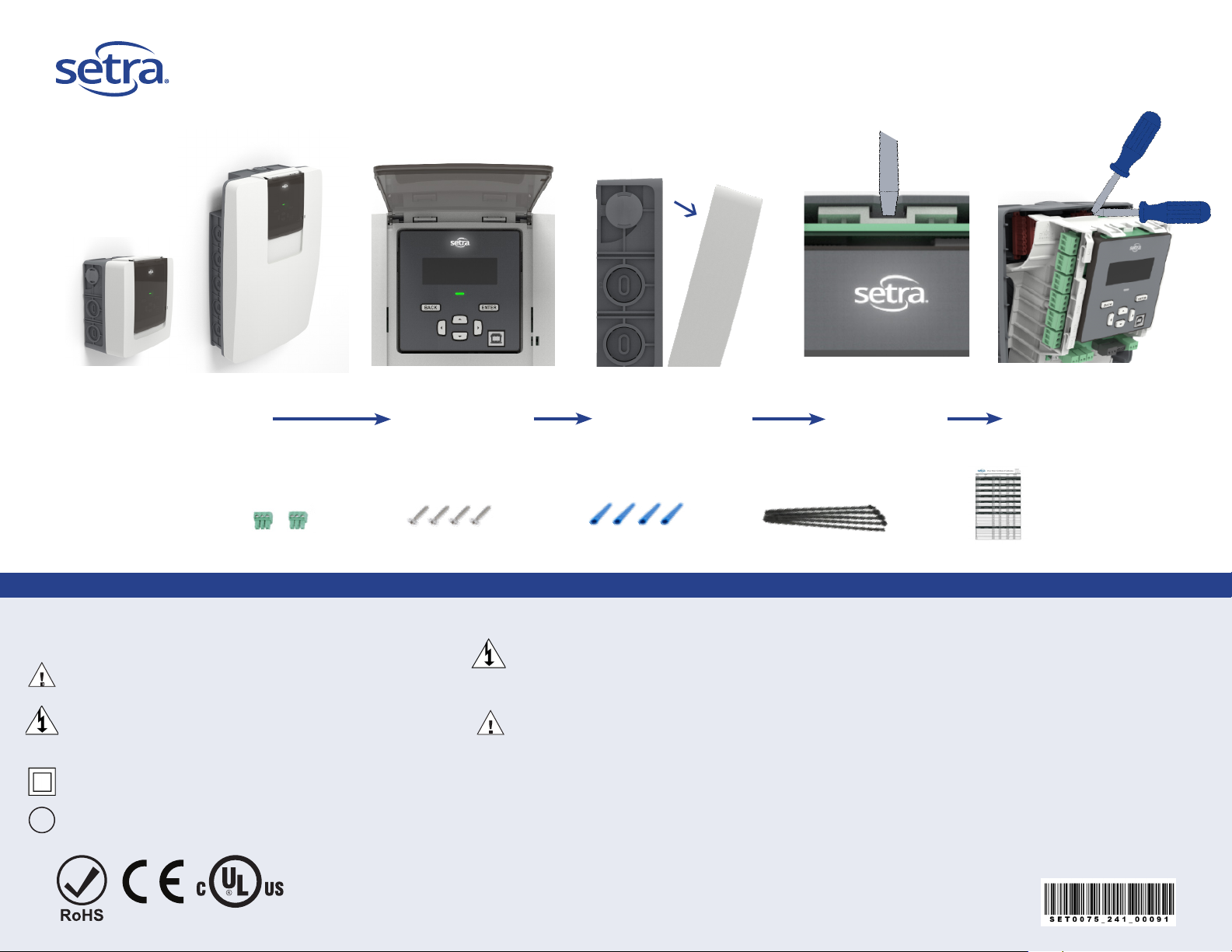
Preparing for Install
Steps
3/12 Load
Remove meter from box
This quick-start guide provides an overview of the safety and installation requirements for the Setra Power Meter product family. Please refer to the full installation and operation manual for details on all features of the meter.
Safety Information
Denotes warning or caution. See manual for a description of
the meanings.
DENOTES HIGH VOLTAGE. RISK OF ELECTRICAL SHOCK. LIFE
THREATENING VOLTAGES MAY BE PRESENT. QUALIFIED
PERSONNEL ONLY.
Equipment protected throughout by double insulation (IEC
536 Class II).
!
Contains additional information pertinent to current subject.
48 Load
CT connector kit
Flip open dust cover Pull front cover forward
Pull down on tabs
Mounting screws
Insert screwdriver
into slot
What’s in the box
Wall anchors
DO NOT EXCEED 347V Line to Neutral or 600V Line to Line. This meter is equipped to monitor loads up
to 347V L-N. Exceeding this voltage will cause damage to the meter to the meter and danger to the user.
Always use a Potential Transformer (PT) for voltages in excess of 347V L-N or 600V L-L. The Setra Power
Meters are 600V Over Voltage Category III device.
To avoid electrical shock or re:
• Review the entire manual before use of the Meter and its accessories.
• Comply with local and national safety codes. Use personal protective equipment to prevent shock and
arc flash injury where hazardous live conductors are exposed.
• Only qualied electrical workers should install this equipment. Such work should be performed only after
reading the full installation and operation manual.
• The equipment must be accessible to authorize personnel only. Equipment must be installed in areas
where access can be restricted.
• If the meter appears damaged or defective or internal fuse brownout, rst disconnect all power to the
meter. Then contact Setra technical support for assistance.
Cable ties
WARNING
Pivot screwdriver up to
remove main assemble
Cal. Cert.
Page 2
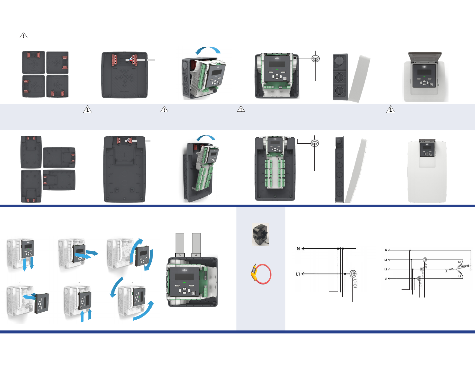
Installation Overview
Prior to installation, the full installation and operation manual are accessible by powering up the meter through USB cable and accessing the help section on the web portal or by visiting www.setra.com
(12 load housing shown)
(3 load meter only has 1 Vin)
3 & 12 Load meter
1. Mount unit in preferred
conduit orientation with
provided mounting screws.
2. After safely de-energizing
the circuit, properly wire in
the lines voltage per local
electrical codes.
48 Load meter
Choosing conduit position
(rotate the display)
1 2 3
Vin 1
3. Install the “Main assembly”
into the back housing until it
locks in place.
Vin 1
+ +
CT Input
4. Following local electrical
codes. Wire in the current
transformers and communication
lines to the meter.
CT Input
CT wiring guide
Load
Split core CT’s
White: + Black: -
L1
5. Install front cover by
engaging the two tabs at
the bottom and rotate the
cover until clicked in-place.
L1
Meter wiring example
2-wire, Single Phase
6. After meter is fully wired,
safely re-energize the circuit
and begin gathering data.
4-wire wye, 3 Phase
LoadSource Source
4 5 6
Conduit location now in the
preferred orientation
Rogowski CT’s
Red: + Black: -
Bare wire: shield
Polarity
Arrow points
towards the load
N
L1
N
L1
L3
L2
Vin CT Input
For additional wiring diagrams please refer to full manual.
L3
L2
Vin CT Input
Page 3

Conguring the meter
Connecting the meter to the PC How the “Halo-dot” works
Voltage setup menu
This menu allows configuration of the voltage input
2
Click “Halo-dot” or
Near connector to begin Voltage input setup
1
1. Connect meter to USB cable
2. Open up web browser on your PC
3. Type http://10.10.5.2 into browser address bar
4. Complete meter setup to desired conguration and upload
to meter
Note: Meter can be powered safely via 5VDC from PC or by
line voltage. Meter setup can be completed pre or post site
installation. Full manuals can be downloaded from web portal
for more details.
General Settings
• Global meter settings
• Meter identication
• Pin-code protection
Pulse I/O
• Enable pulse I/O
• Dene pulse type
• Dene scaler & width
SS-SPM QuickStart Rev. B 2 /2020
Voltage input 2
Expected Voltage on L1 (VAC)
480
400
Actual Voltage on L1 (VAC)
No voltage present
Service Type
4-wire wye
Navigating the meter
Voltage inputs
• Dene input voltage
• Wiring conguration
• Step down PT settings
Alarm setup
• Select alarm type
• Dene alarm thresholds
• Dene alarm indication
Load setup
• ID measured loads
• Dene CT grouping
• Dene voltage input
Installation report
• Conguration record
• Initial meter readings
• Site/installer information
CT inputs
• Select CT type
• CT polarity correction
• Copy/paste CT type
Collect data
• Send data to EMS/BAS
• Locate energy losses
• Save energy
Communication
• BACnet/IP
• BACnet MS/TP
• Modbus TCP
• Modbus RTU
Visit
www.setra.com\power-meter
for full user guide and
installation manual or
call +1 978.263.1400 for
technical support or email
techsupport@setra.com
 Loading...