

Page 1
Setra Local Display
Model LD330
Installation and Operating Instructions.
Setra’s Model LD330 is a small local display designed for convenient
in-line installation. It can be used with voltage output and current output tranducers
4-pin bayonet connectors (which meet dimensional requirements of MIL-C-26482
and the MIL STD 3116) Amp jack, 15 Pin and
9 Pin D-Sub connectors.
1.0 INSTALLATION
The LD330 can be supplied with a variety of integral electrical connectors to connect to the
mating connectors on the transducer. Consult part number chart below to determine the
proper configuration. For setting optimum viewing angle, the LD330 display housing can
rotate, at least 270 degrees, with respect to the connector. DO NOT ATTEMPT TO FORCE
ROTATIONAL ADJUSTMENT BEYOND STOP POSITION.
The LD330 is available in a variety of configurations.
2.0 ELECTRICAL CONNECTIONS
The LD330 can be supplied with different style connectors to the input transducer and to
the power supply. The power supply can be supplied with cable, also. Confirm the electrical
connection supplied , and refer to the appropriate column below for
proper connections.
2.1 Voltage Units
9 PIN 15 PIN 5 PIN
CABLE BAYONET D-SUB D-SUB MINI-DIN MOLEX
CONNECTION WIRE PIN PIN PIN PIN
+ EXCITATION RED A 4 7 1 2
+ OUTPUT GREEN B 1 2 2 1
– OUTPUT WHITE C 8 12 4 4
– EXCITATION BLACK D 9 5 5 5
CASE GND DRAIN SHELL SHELL SHELL 3 6
2.2 Current Units
9 PIN 15 PIN 5 PIN
CABLE BAYONET D-SUB D-SUB MINI-DIN MOLEX
CONNECTION WIRE PIN PIN PIN PIN
+ EXCITATION RED A 4 7 1 2
– EXCITATION BLACK D & B 9 5 4 5
CASE GND DRAIN SHELL SHELL SHELL 3 6
1
Page 2
3.0 PANEL-MOUNT
CONFIGURATION
1.00
25.4
ø0.15
3.81
1.55
39.37
If the panel-mount configuration is
supplied, see Figure 1 for cut-out
dimensions. Insert the panel-mount
display through the front and secure
2.25
57.2
1.88
47.8
1.73
43.18
Cut Out
Dimensions
to the panel with four mounting
screws (not supplied).
1.65
41.9
Figure 1
4.0 CALIBRATION
The LD330 is factory calibrated to display engineering units. The multi-turn pots on the front
face are for zero and span display adjustment. Setra recommends that the zero adjustments
be done using the transducer zero potentiometer whenever possible. The display zero
potentiometer should only be used for minor adjustments. Never adjust the span potentiometer unless proper calibration equipment is used and proper calibration procedures are
followed.
4.1 Zero & Sensitivity Adjustment
The zero and sensitivity (span) potentiometer are located on the front of the unit just
under the digital display. Remove the protective plugs to access the potentiometers.
1. Apply zero pressure to the transducer and adjust the LD330's zero potentiometer if
the LD330 does not display "0".
Note: For a compound range (eg -14.7 to 100 psig unit) apply "0" psig pressure to
the transducer and adjust the LD330 zero potentiometer until the display is "0". Do
not apply -14.7 psig and attempt to adjust the display to "-14.7".
2. Apply full scale output to the transducer/transmitter and adjust the span potentiometer on the LD330 if the LD330 does not display the correct value. If the adjust-
ment seems sensitive verify that the LD330 is the correct range for your transducer.
Repeat steps 1 and 2 as necessary.
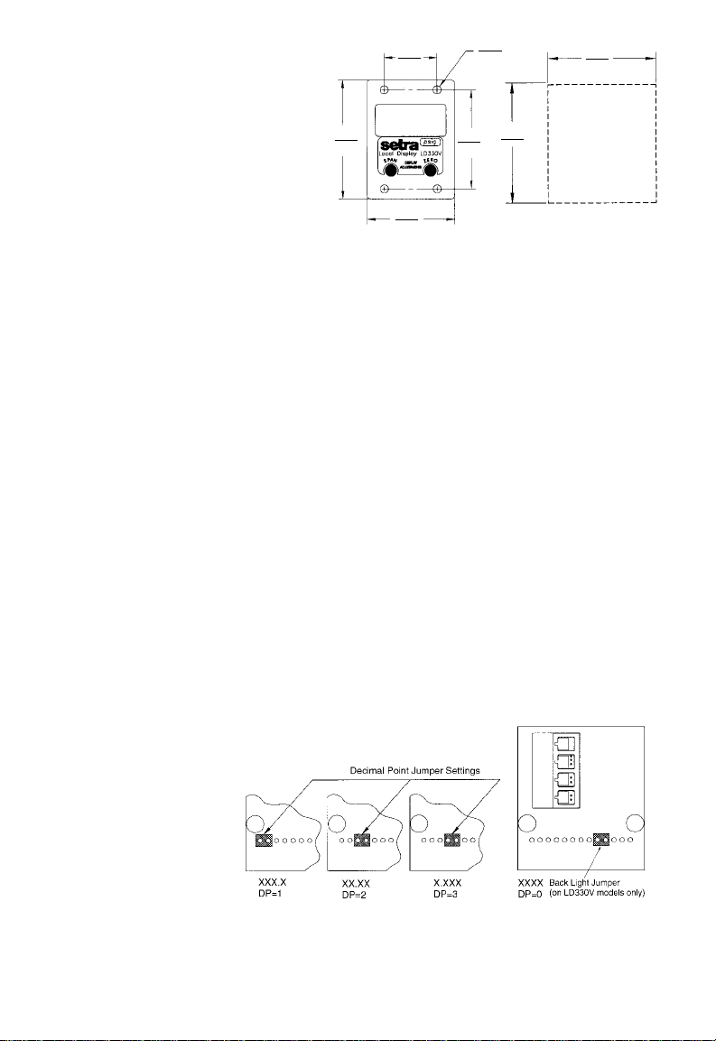
4.2 Decimal Points
The LD330 decimal point is factory set to custom specified range. Figure 2 below
shows the jumper settings required for decimal point settings.
To access this jumper, remove the 2 screws on the backside of the
LD330 housing and
remove the back
cover. Remove jumper
if decimal point is not
required.
4.3 Backlighting
The LD330V comes
standard with green
backlighting. LD330C is not
offered with backlighting. To disable backlighting of LD330V, remove the Back Light
Jumper shown in figure below.
2
Figure 2
Page 3

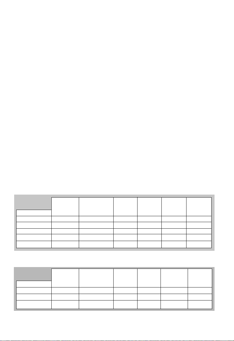
5.0 SPECIFICATIONS
LD 330V LD 330C
Display Voltage Input Display Loop Powered Display
Digits -999 to 1999 -999 to 1999
Type 7 Segment LCD, Green Backlight 7 Segment LCD
Polarity Automatic (-) display Automatic (-) display
Overload 1 followed by blank display 1 followed by blank display
Accuracy 0.25% of reading ±1count 0.25% of reading ±1 count
Environmental
Operating Temp. 32°F to 140°F (0C to 60C) 32°F to 140°F (0C to 60C)
Storage Temp. -40°F to 158°F (-20C to 70C) -40°F to 158°F (-20C to 70C)
Temp. Coeff. 100 ppm/C 100 ppm/C
Electrical Data
Input Signal 0.2 to 5.2 VDC 4-20 mA loop powered
Excitation 8 VDC to 30 VDC 4 VDC max voltage drop
300k ohm min input impedance
30 mA current consumption
3 mA with backlight disabled
At 32 VDC = 15 mA
Zero/Span Adjust Multi-Turn potentiometers Multi-Turn potentiometers
Protection Reverse polarity protection 100 mA current limit
(Backlit Optional)
Example: Part No. 3301-V-3-C-B-T is a Model 330 with 0.2 to 5.2 VDC input, 100.0 pressure range, compound pressure,
TABLE 1 CONFIGURABLE PART NUMBER
Bayonet-Female-Bottom connection to transducer and a Bayonet-Male-Top connection to power supply.
Model
3301 = 330
V = 0.2 - 5.2 VDC
M = 0-5 VDC
N = 0.2 - 10.2 VDC
L = 0-10 VDC
C = 4-20 mA
B = 4-20 mA
Input
Backlit
Pressure Range
PSI Range
1 = 25.0
2 = 50.0
3 = 100.0
4 = 250
5 = 500
6 = 1000
7 = 3.00Kpsi
Bar Range
A = 1.70
B = 3.40
C = 7.00
D = 17.0
E = 34.0
F = 70.0
G = 210
Pressure
G = Gage
C = Compound
A = Absolute
Electrical Connection
to Transducer
B=Bayonet, Female, Bottom
R=Bayonet, Female, Rear
L=Bayonet, F emale, Lower Rear
H=Bayonet, Female , High Rear
M=Mini-Din, Rear
N=Mini-Din, Bottom
D=15 Pin D-Sub, Rear
E=9 Pin D-Sub, Bottom
F=Molex Rear
Electrical Connection
to Power Supply
T=Bayonet, Male, Top
R=Bayonet, Male , Rear
C=6ft. Cable, Rear
K=6ft. C able, Top
D=15 Pin D-Sub, Bottom
E=9 Pin D-Sub, Bottom
B=Bayonet, Male, Bottom
F=1 ft. Cable, Top
J=2 ft. Cable, Top
L=3 ft. Cable, Top
U=4 ft. Cable, Top
V=5 ft. Cable, Top
W=7ft. Cable, Top
1=1ft. Cable, Rear
2=2 ft. Cable, Rear
3=3 ft. Cable, Rear
4=4 ft. Cable, Rear
5=5 ft. Cable, Rear
7=7 ft. Cable, Rear
Options
PN = Panel Mount
(Panel Mount
is not
available for
4-20 mA
Backlit, Code B)
NONE (leave blank)
for
Standard
Display
3
Page 4

RETURNING PRODUCTS FOR REPAIR
Please contact a Setra application engineer (800-257-3872, 978-263-1400) before
returning unit for repair to review information relative to your application. Many times
only minor field adjustments may be necessary. When returning a product to Setra,
the material should be carefully packaged and shipped prepaid to:
Setra Systems, Inc.
159 Swanson Road
Boxborough, MA 01719-1304
Attn: Repair Department
To assure prompt handling, please supply the following information and include it
inside the package or returned material:
1. Name and phone number of person to contact.
2. Shipping and billing instructions.
3. Full description of the malfunction.
4. Identify any hazardous material used with product.
Notes: Please remove any pressure fittings and plumbing that you have installed and
enclose any required mating electrical connectors and wiring diagrams.
Allow approximately 3 weeks after receipt at Setra for the repair and return of the unit.
Non-warranty repairs will not be made without customer approval and a purchase
order to cover repair charges.
Calibration Services
Setra maintains a complete calibration facility that is traceable to the National Institute
of Standards & Technology (NIST). If you would like to recalibrate or recertify your
Setra pressure transducers or, please call our Repair Department at 800-257-3872 (978-
263-1400) for scheduling.
WARRANTY AND LIMITATION OF LIABILITY
SETRA warrants its products to be free from defects in materials and workmanship, subject to the following terms and conditions: Without charge, SETRA will repair or replace
products found to be defective in materials or workmanship within the warranty period; provided that:
a) the product has not been subjected to abuse, neglect, accident, incorrect wiring not our own, improper installation or servicing, or use in violation of instructions
furnished by SETRA;
b) the product has not been repaired or altered by anyone except SETRA or its authorized service agencies;
c) the serial number or date code has not been removed, defaced, or otherwise changed; and
d) examination discloses, in the judgment of SETRA, the defect in materials or workmanship developed under normal installation, use and service;
e) SETRA is notified in advance of and the product is returned to SETRA transportation prepaid.
Unless otherwise specified in a manual or warranty card, or agreed to in writing and signed by a SETRA officer, SETRA pressure and acceleration products shall be warranted for
one year from date of sale.
The foregoing warranty is in lieu of all warranties, express, implied or statutory, including but not limited to, any implied warranty of merchantability for a particular purpose.
SETRA’s liability for breach of warranty is limited to repair or replacement, or if the goods cannot be repaired or replaced, to a refund of the purchase price. SETRA’s liability for all
other breaches is limited to a refund of the purchase price. In no instance shall SETRA be liable for incidental or consequential damages arising from a breach of warranty, or
from the use or installation of its products.
No representative or person is authorized to give any warranty other than as set out above or to assume for SETRA any other liability in connection with the sale of its
products.
159 Swanson Road, Boxborough, MA 01719-1304
Tel: 800-257-3872/978-263-1400, Fax 978-264-0292
8
Email: sales@setra.com, Web: www.setra.com
SS2027 Rev.B 10/10/00
 Loading...