

Page 1
TM
Quickstart Guide
1.Intended Use
Thank you for purchasing the Setra FLEX, the industry’s most advanced and flexible room environmental monitor.
Setra FLEX is designed for indoor use only to monitor critical environments by providing differential pressure indication and additional
parameters such as temperature, relative humidity, air changes per hour, and user-dened information. Typically this is between a monitored
room and a reference space such as a corridor or ante room. The unit also provides monitoring, control, alarm, and communications
functions.
Typical Applications:
1. Hospitals – patient isolation and protection rooms, operating suites, intensive care and emergency rooms.
2. Pharmaceutical, semiconductor, precision manufacturing and clean rooms
3. Laboratories – medical research, BSL (bio safety labs), radiation, vivarium, toxic metals and chemicals.
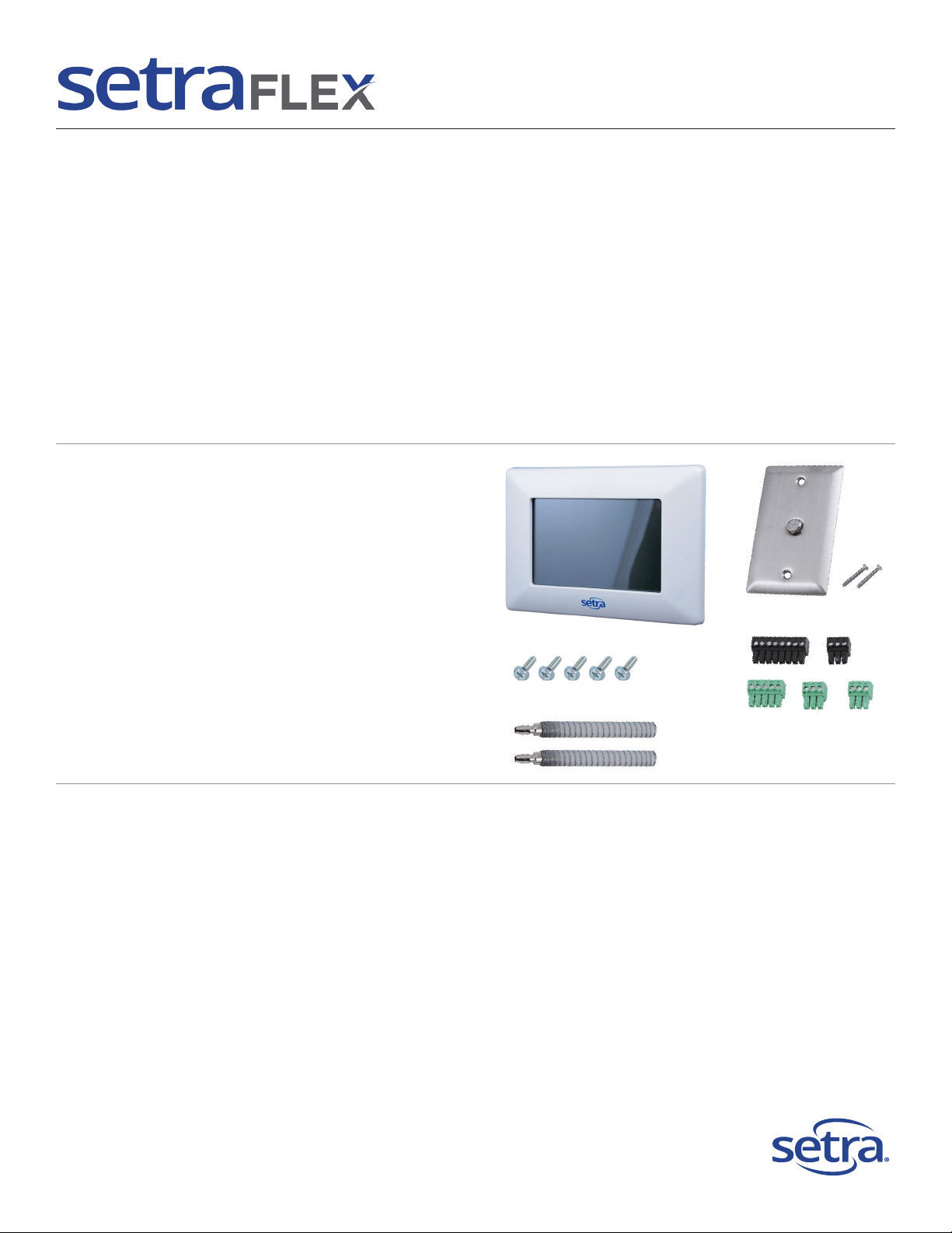
Included in the box
a) FLEX unit
b) FLEX unit mounting screws
c) Tubing
d) Room pressure snubber (RPS, if ordered)
and mounting screws
e) Electrical connector kit
a
d
Quantity of box contents may vary.
b
e
c
(photos not to scale)
Parts required and to be supplied by installer
To mount and install properly, the following components are required.
NOT INCLUDED and required for each FLEX unit:
• Triple Gang Double Deep Metal Electrical Box, RACO 697 or Appleton M3-350 or equivalent: 1
(a single-deep box may be used if no on-board pressure sensor was ordered)
• Green grounding screw: 1
• Power and signal wiring, as needed
• ¼” pressure tubing to run from the room(s) to the FLEX unit
• Transformer, 24 VAC
• Door Switch SPDT or SPST, N.O., as needed
• Remote Pressure Transducers, as needed
• Remote Annunciators, as needed
Setra Systems, Inc.
159 Swanson Road, Boxborough, MA 01719
800.257.3872 • www.setra.com
Page 2
B+
GND
+24V
L1
L2
+24V
AI
VDC
COM
SERIAL
(PROPRIETARY)
+24V
UI1
COM
+24V
UI2
COM
UI3
COM
B
A
Z
Y
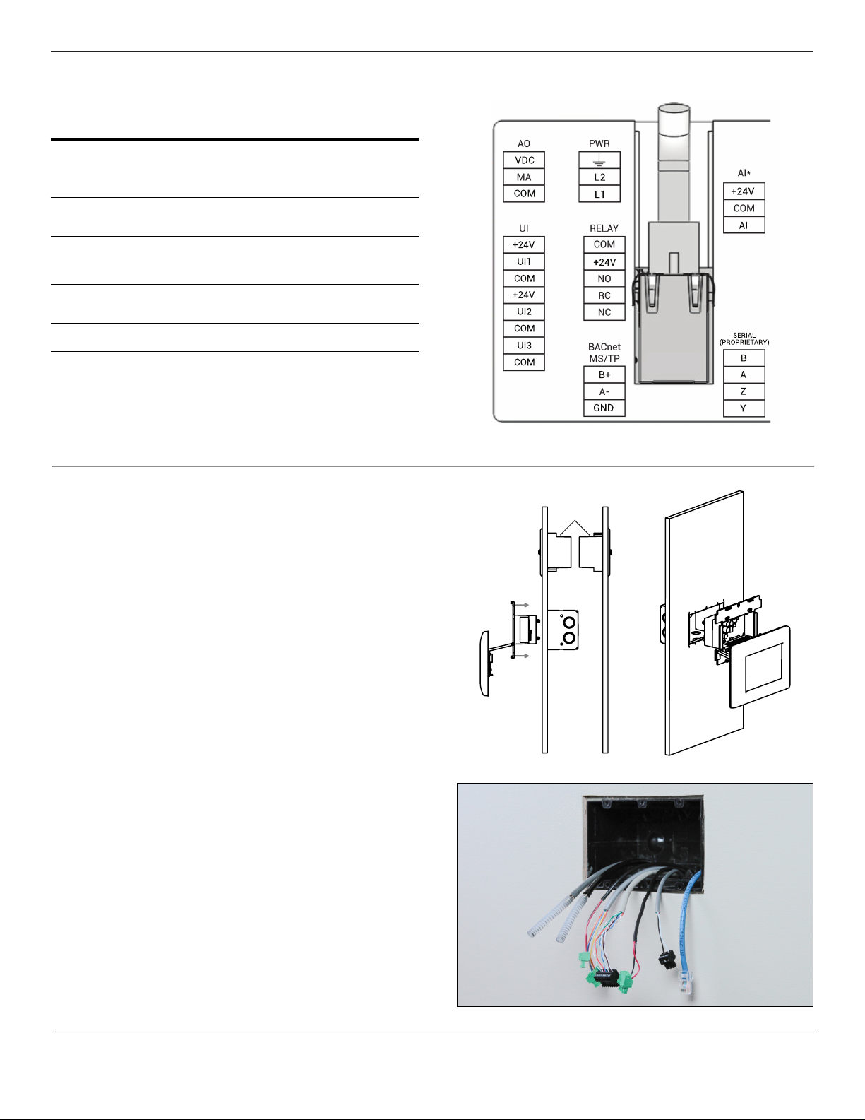
2. Wiring
Inputs & Outputs
Universal inputs (3)
Analog input (1)
Analog output (1)
Relay output (1)
Wire
0-5 VDC, 0-10 VDC, or 4-20 mA input signal*
Congurable for either Analog or Digital signals. Use
external sensors for pressure, temperature, humidity, or
any suitable application. Use as digital input for door, HVAC
Dedicated for use as input for either on-board pressure
0-5 VDC, 0-10 VDC, or 4-20 mA output signal. Use as PI
control loop to modulate reheat valves or other analog
driven devices, pressure output signal, or mirror an input
annunciator or other NO/NC applications. Contact rating
Stranded shielded twisted pair, 16-24 AWG .14-1.5 mm2
lter DP, or duct static DP pressure switch.
transducer, or general AI input. Used only when no
signal. Can be assigned to any room parameter.
24 VDC SPDT NO/NC Relay. Use as remote alarm
transducer is purchased on unit.
2.0A @ 30 VDC
cross sectional area
Expansion I/O module
*Installer provided 250Ω resistor required for 4-20mA signal
8 Universal Inputs, 4 Analog Outputs, 4 Relay Outputs
3. Rough-In
• Ensure rough-in box is ready to receive the RPS
a) Setra RPS Reference Pressure Side
b) 1-Gang Electric Box
c) Setra RPS Room Pressure Side
d) Setra FLEX Unit (Display hinges down during installation then
snaps in place when mounting is complete)
e) Setra FLEX Unit (may be mounted inside or outside room)
f) Wall cavity
g) Electrical Box (3-Gang double-deep if using on-board sensor,
single deep if no on-board sensor)
• Ensure rough-in box is ready to receive the FLEX unit
b
a
e
c
g
d
f
Phone: (800) 257-3872 | Fax: (978) 264-0292 | www.setra.com
Page 3
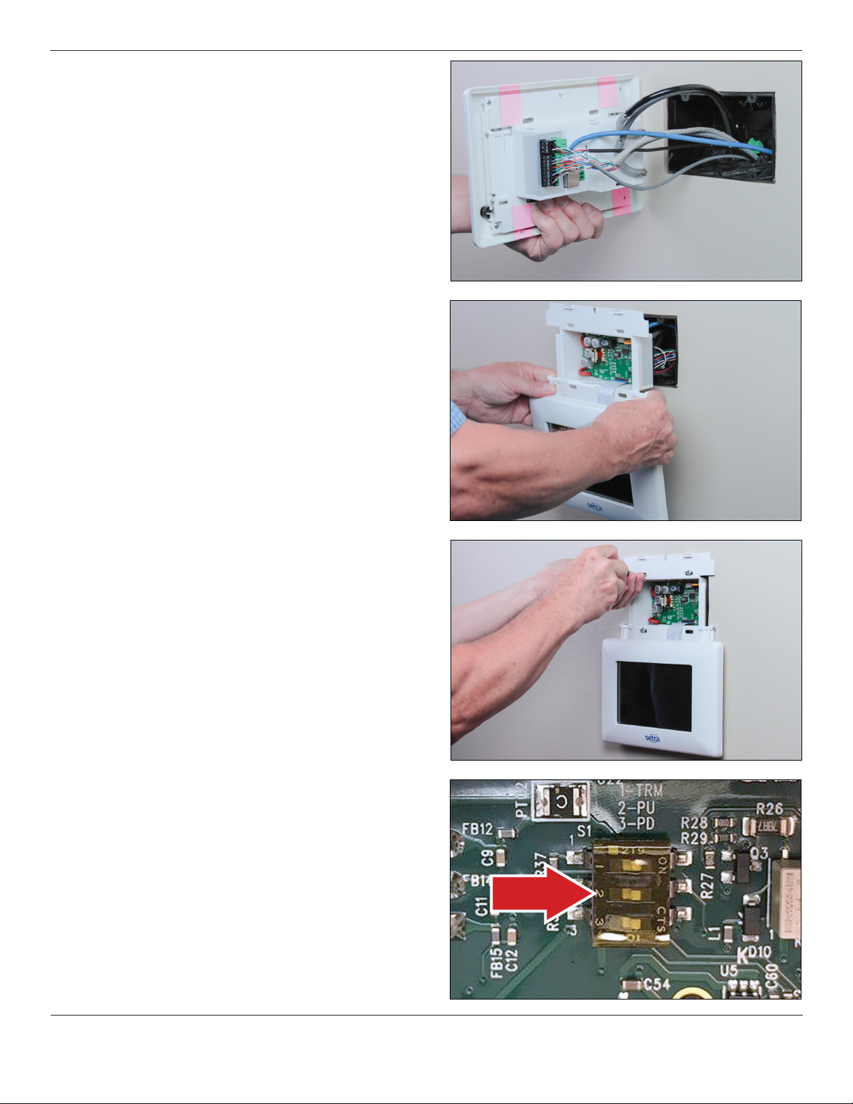
4. Installation
• Make the nal connections by pushing the removable
connectors and wires into the back of the FLEX unit. If
connecting BACnet/IP, insert the RJ-45 cable into the Ethernet
port. If connecting pressure tubing, align HIGH and LOW ports
to their appropriate pressure sensor connections with anti-
kink tubing and secure in place.
• Slide the FLEX unit back into the wall, taking care to not crimp
tubing or damage wires.
• Secure the FLEX base unit into the electrical box with the four
(4) mounting screws provided. Allow the FLEX display to hang
below the mounting box, taking care so that the display does
not get damaged by tools.
• BACnet MS/TP hardware is implemented as isolated RS485.
Wire to Connector COMM, labeled BACNET. Connect TX line
to B (+), RX to A (-) and ground wires to GND. Connect shields
together with wire nut. Hardware conguration is done using a
three position dip switch located in the upper center section of
the rear PCB. Use a small flat blade screwdriver or pen to push
the switch to the right to turn the function on, or to the left to
turn the function off. If the unit will be at the end of the line,
the terminating resistor can be enabled by pushing position
1 to on.
© Setra Systems, Inc. All Rights Reserved. The Setra Systems name and logo are registered trademarks of Setra Systems, Inc.
Page 4
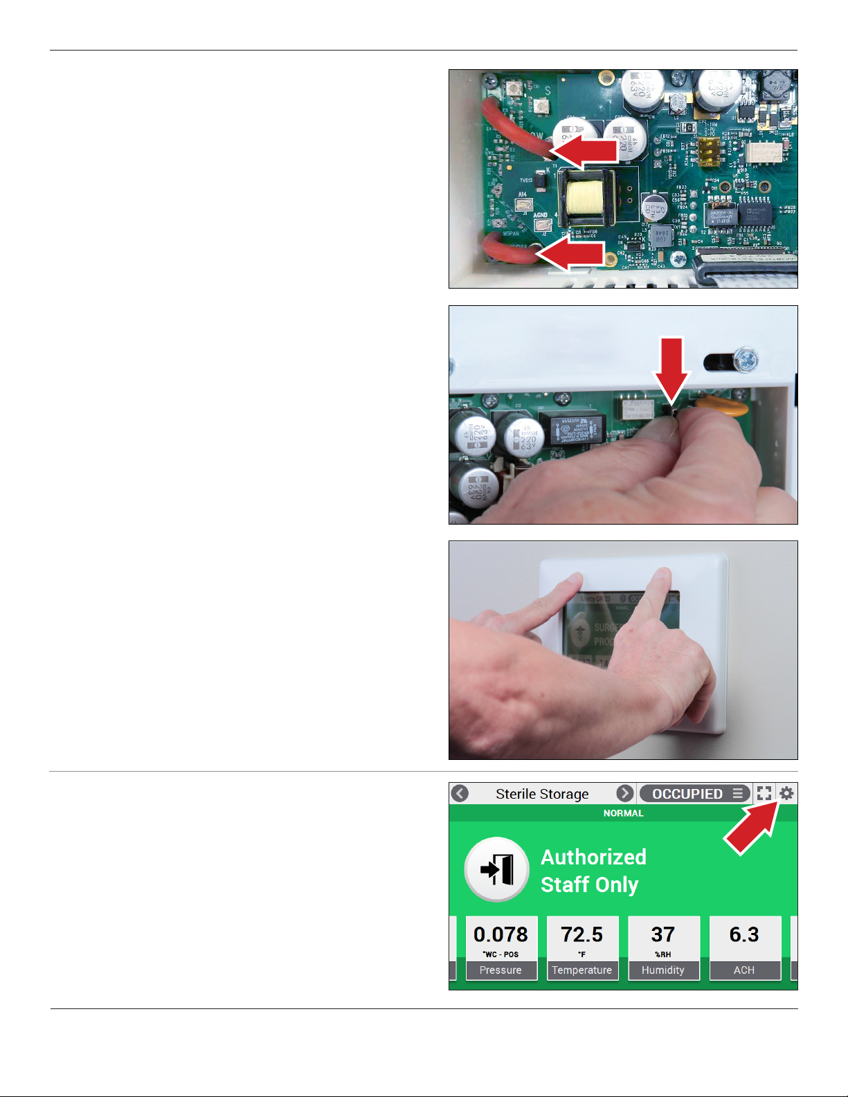
• With the FLEX display hanging open and unit powered, re-zero
the sensor to ensure accurate operation:
1. Remove one end of each pressure tube (shown here)
2. Access “Settings” > “Maintenance” > “Pressure Calibration”
3. With tubes disconnected, press “Adjust Zero”
4. Reconnect tubes
• The unit is now ready for nal mounting
• If live power is already turning on FLEX, power can be cycled on
FLEX by removing the J6 jumper on the unit. This can be done
by hand, or carefully with non-conductive pliers. Normally,
FLEX is continuously powered and this jumper does not need
to be accessed.
• Swivel up the FLEX display, and push rmly at the frame just
above and just below the touch screen. The display will snap
into place and seal against the wall surface.
5. Power Up Conguration
• Access the “cog wheel” on the top-right of the FLEX display to
congure the unit.
Phone: (800) 257-3872 | Fax: (978) 264-0292 | www.setra.com
Page 5

• Use “Device Conguration” for initial setup.
• The next seven menus (three tiles over four) permit complete
conguration of your FLEX unit. Detailed instructions for each
menu can be found in the FLEX Installation & Operations Guide.
6. FLEX Home Screen
Room name
(Up to 3 congured))
Two lines of text
provide notices to
staff, or none
Select from 32 icons
to represent room
use or none
Badges show room
parameters, values,
units, and state
Room navigation,
to view home screen of
rooms 2 and 3
Full screen mode
Pull-down room
proles, user-dened,
to set new monitor
and control setpoints
in effect
Set up unit
Banner indicates room
condition: NORMAL,
WARNING, ALARM,
or STANDBY
Two icons enable alarm
silencing. latch alarm
reset, or door indicator
Badges 5 and 6
(if congured) appear
off-screen and can be
accessed by swiping
left of right
© Setra Systems, Inc. All Rights Reserved. The Setra Systems name and logo are registered trademarks of Setra Systems, Inc.
Page 6

7. Specications
Physical Description
Dimensions
Mounting
Case
Weight
Display
Display brightness
USB port
Audible alarm
(215.0mm x 160.0mm x 16.51mm)
Triple-gang, double deep electrical box. RACO 697,
7” Projected Capacitive (PCAP) multitouch. 800 x 480
Micro-USB port for conguration cloning between units
Dual piezo with 3 volume levels (0-75 dB max.)
pixels. Usable with medical gloves.
9.25” W x 6.3” H x 0.65”D
Appleton M3-350, or equivalent
Fire-retardant plastic UL94 V-0
and software upgrades.
Communications
Protocols (BACnet objects can be found at setra.com) BTL- Compliant
BACnet/IP using IPv4, Ethernet CAT5 cables with RJ45
BACnet MS/TP up to 76.8 kbps, 3-conductor, twisted,
shielded 16-24 AWG cable
Electrical
Power
Power draw
Wire
Connections
24 VAC (18-30 VAC operational), 50-60 HZ
13 W max, 10 W typical
2 or 3-conductor (depending on application)
stranded unshielded twisted pair, 16-24 AWG
Removable Terminal Blocks
Regulatory Compliance
CSA, CE, RoHS, WEEE
Specications subject to change without notice.
2 lbs
1-7
Environmental Data
Operating temp. °F (°C)
Storage temp. °F (°C)
Operating humidity
Ingress Protection (IP) rating
5 to 95% RH (non-condensing)
32 to 120 (0 to 50)
-40 to 185 (-40 to 85)
IP54
Chemical Resistance
Exposed surfaces are chemically resistant to vaporized hydrogen peroxide (VHP),
formaldehyde, chlorine dioxide (clidox), perchloric acid, sodium hypochlorite 3-6%
(bleach), quaternary ammonium 7% in 1:128 tap water (ammonia).
Performance
Accuracy RSS
Non-linearity (BFSL)
Hysteresis
Non-repeatability
Span setting tol.
Zero/span shift % FS
Overpressure
Pressure media
Pressure ttings
Altitude
Position
± 0.03% PSI (±0.05% FS)
±1 PSI (15” WC for ≤0.10” WC FS)
Air or non-conductive, non-explosive gases
3/16” barbed ttings
6562 ft. (2000 m) max.
Housing to be 90° in reference to level surface, ±5°
±0.25%
±0.24%
±0.05%
±0.05%
±0.5% Rdg
8. Maintenance
• The FLEX is designed to operate in an indoor environment, monitoring clean, dry air.
• Upon nal installation of the FLEX Environmental Monitor, no routine maintenance is required. An annual check of system calibration is
recommended. FLEX is not eld serviceable and should be returned if repair is needed (eld repair should not be attempted and may void
warranty). Be sure to include a brief description of the problem plus any relevant application notes. Contact customer service to receive
a return goods authorization number before shipping.
• WARNING: Do not blow into the pressure tubing or ttings with mouth, compressed air, or canned air. Such actions may permanently
damage the pressure sensor. Do not clean or wash-down FLEX with industrial cleaners or solvents other than those approved in
specications. Do not immerse unit.
Phone: (800) 257-3872 | Fax: (978) 264-0292 | www.setra.com
Page 7

9. Returns
When returning a product to Setra Systems, the material should be carefully packaged and shipped prepaid to:
Setra Systems, Inc.
159 Swanson Road
Boxborough, MA 01719-1304
Attn.: Repair Department
To assure prompt handling, please refer to return instructions at the following URL:
http://www.setra.com/tra/repairs/cal_rep.htm.
10. Warranty and limitation of liability
SETRA warrants its products to be free from defects in materials and workmanship, subject to the following terms and conditions: Without charge, SETRA
will repair or replace products found to be defective in materials or workmanship within the warranty period; provided that:
a) the product has not been subjected to abuse, neglect, accident, incorrect wiring not our own, improper installation or servicing, or use
in violation of instructions furnished by SETRA;
b) the product has not been repaired or altered by anyone except SETRA or its authorized service agencies;
c) the serial number or date code has not been removed, defaced, or otherwise changed; and
d) examination discloses, in the judgment of SETRA, the defect in materials or workmanship developed under normal installation, use
and service;
e) SETRA is notied in advance of and the product is returned to SETRA transportation prepaid.
Unless otherwise specied in a manual or warranty card, or agreed to in writing and signed by a SETRA ofcer, SETRA pressure, humidity, and acceleration
products shall be warranted for one year from date of sale.
The foregoing warranty is in lieu of all warranties, express, implied or statutory, including but not limited to, any implied warranty of merchantability for a
particular purpose.
SETRA’s liability for breach of warranty is limited to repair or replacement, or if the goods cannot be repaired or replaced, to a refund of the purchase price. In
no instance shall SETRA be liable for incidental or consequential damages arising from a breach of warranty, or from the use or installation of its products.
No representative or person is authorized to give any warranty other than as set out above or to assume for SETRA any other liability in connection with the
sale of its products.
For all CE technical questions, contact Setra Systems, USA. EU customers may contact our EU representative Hengstler GmbH, Uhlandstr 49, 78554 Aldingen,
Germany (Tel: +49-7424-890; Fax: +49-7424-89500).
Safety Precautions
This product conforms to UL 61010-1/61010-2-201 and CSA CSA22.2 No. 61010-1/61010-2-201 safety standards
Pollution Degree 2, and Measurement Category 2.
To ensure the safe operation and service of the device, follow these instructions closely. Failure to observe warnings can
result in severe personal injury or permanent damage to the device.
• This product is for indoors use only
• Use a Class-2 transformer of the appropriate size to supply power to the device
• Relay shall only be used to switch load up to 30VDC 2A
• Temperature inside enclosure may exceed 60˚C under normal operation. Select appropriate cable or wire rating for
connection. Avoid touching electronics components with bare hands to prevent personal injury
• All wiring must conform to national and local codes and regulations
• Observe ESD general practice. Wear ESD wrist strap to install and service the device
© Setra Systems, Inc. All Rights Reserved. The Setra Systems name and logo are registered trademarks of Setra Systems, Inc.
Page 8

11. Support
Setra FLEX
Installation & Operation Guide
Technical Support
Setra FLEX
Data Sheet
SS-FLEX Quickstart Rev. E 05/2019
www.setra.com800.257.3872 techsupport@setra.com
Setra Systems, Inc.
159 Swanson Road, Boxborough, MA 01719
800.257.3872 • www.setra.com
 Loading...