

Page 1

AccuSenseTM Model ASM
High Performance Pressure Transducer
Installation Guide
Description
The AccuSense
designed for accurate, reliable pressure measurements. It has a high level analog output
signal, excellent stability, and secure calibration which makes it ideal for high performance
industrial, laboratory, and engine test cell applications.
TM
Model ASM pressure transducer is a high performance pressure transducer
1.0 General information
Every Model ASM has been tested and calibrated before shipment. Specic performance
specications are shown on page 3 of this Guide. Setra Systems ASM pressure transducers
sense gauge, absolute, or vacuum gauge pressure and convert this pressure difference to
a proportional high level analog output. Voltage outputs of 0 to 5 VDC or 0 to 10 VDC, and
current output of 4 to 20 mA are offered.
2.0 Electrical installation
2.1 Media Compatibility
Model ASM transducers are designed for use with gases and liquids compatible with 17-4PH
stainless steel.
2.2 Environment
The operating temperature limits of the ASM are -40°C to +85°C (-40°F to +185°F)
The compensated temperature range is -20°C to +60°C (-4°F to +140°F)
2.3 Pressure Fittings
Available pressure ttings are given in table below:
Pressure port
code
1F 1/8”-27 NPT Internal
1M 1/8”-27 NPT External
2F 1/4”-18 NPT Internal
2M 1/4”-18 NPT External
J7 7/16”-20 SAE External
J8 7/16”-20 SAE Internal
Fitting description:
process port / ref port
1
Page 2
2.4 Installation of Pressure Fittings
Your transducer is designed for the most accurate operation when subjected to pressures
within the designated pressure range. Refer to page 4 for proof pressure limits.
Standard sealants such as Teflon pipe tape generally are satisfactory on NPT threads. For
the most sensitive pressure ranges, excessive high torquing of a metal pressure tting may
cause slight zero shift which may be trimmed out using the zero adjustment. Use of a plastic
tting often shows no noticeable zero shift. The torquing effect does not appreciably affect
linearity or sensitivity. The 3/4 in. wrench flat (Hex) on the unit must be used when installing
the positive pressure tting.
3.0 Electrical installation
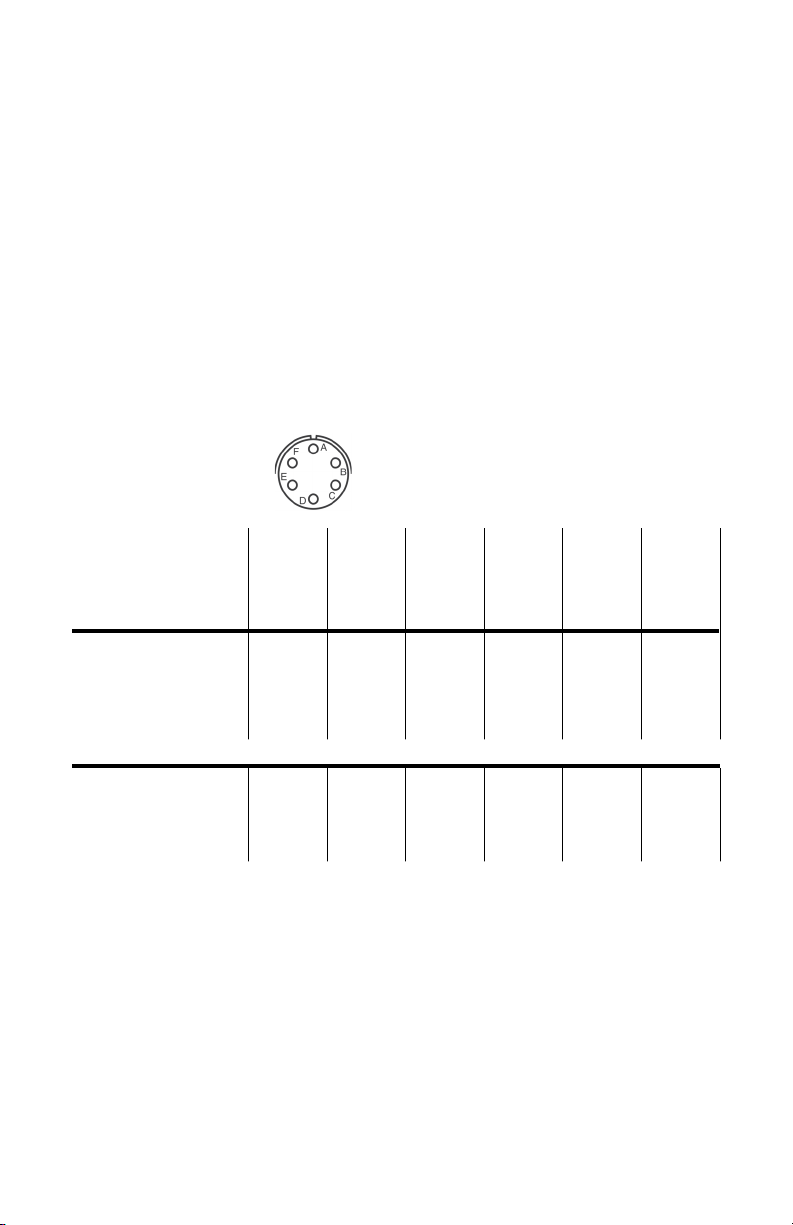
3.1 Electrical Connections
ASM is available with a cable, or bayonet connector options having different connector pin-
outs shown in table below:
Connector
Viewed from Front
Electrical
Connection
Current Voltage
+ EXC + EXC Red A A A C A D
- EXC - EXC Black D B B D C C
NA + Sig Out Green B C D A F B
NA - Sig Out White C D C B E A
Reserved for communication with SecureCalTM calibration module
SecureCal™ Blue E E E E B E
SecureCal™ Brown F F F F D F
Shield
drain wire
Wire
Color
Exposed
Code B3
(Standard)
Bayonet
Connector
Pinout
Case Case Case
Code B4
Option
Bayonet
Connector
Pinout
Code B5
Option
Bayonet
Connector
Pinout
Code B6
Option
Bayonet
Connector
Pinout
Code B7
Option
Bayonet
Connector
Pinout
Code B8
Option
Bayonet
Connector
Pinout
CAUTION:
Connecting -EXC to positive excitation and +SIG to negative excitation at the same time may
damage the unit.
3.2 Voltage Output Units
The Model ASM voltage units are a four-wire type circuit energized thru +EXC and -EXC ter-
minal with 0-5 VDC or 0-10 VDC analog output through the +SIG Out and -SIG Out terminals.
3.3 Current Output Units
The Model ASM current units are a two-wire loop-powered 4 to 20mA current output and
deliver rated current into any external load of 0 to 800 ohms.
2
Page 3
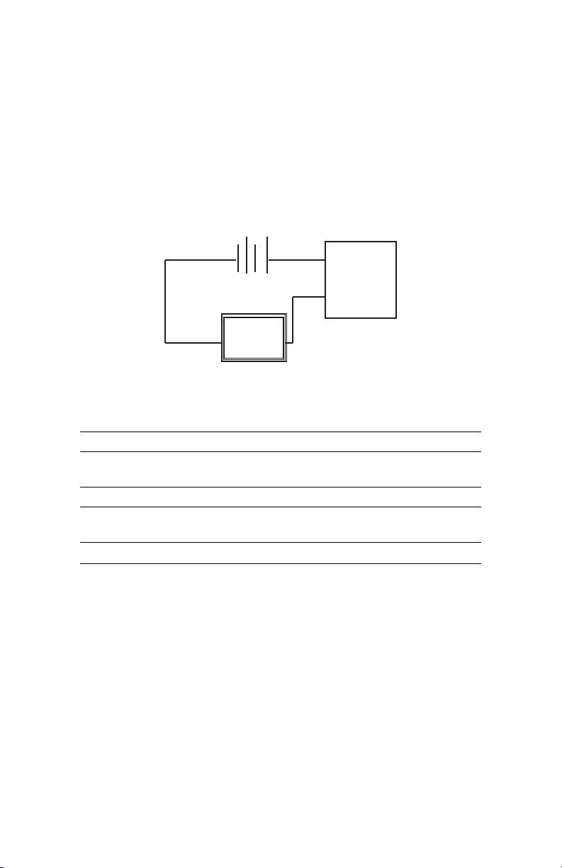
The current flows into the +EXC terminal and returns back to the power supply through the
-EXC terminal (See Diagram 1). Note: The +SIG Out and -SIG Out terminals are not used.
The power supply must be a DC voltage source with a voltage range between 9 and 30 VDC
measured between the + and - terminals. The unit is calibrated at the factory with a 24 VDC
loop supply voltage.
3.4 Cable for Bayonet Connectors
For good EMC performance, shielded cable shall be used and grounded to earth ground. Cable
shall only be used within a building and not be longer than 30 m (100 ft.).
Diagram 1:
+
ASM
9 to 30 VDC
Current
Monitoring
Device
_
Electrical data:
Signal output ranges 0-5 VDC, 0-10 VDC (4-wire), 4-20mA (2-Wire)
Nominal excitation 24 VDC
Excitation range
Current/Power consumption* <23mA
Circuit response time
Warm-up, environmental Within +/-0.02%FS after 15 min Warm-up Time
Miswiring Reverse Excitation Protection
9-30V DC (5V DC & 4-20mA output)
15-30V DC (10V DC Output)
<10ms (Voltage Version),
<80ms (4-20mA Version)
4.0. Calibration
The ASM transducer is factory calibrated and should require no eld adjustment if mounted
in a vertical position. Whenever possible, any zero and/or span offsets should be corrected by
software adjustment in the user’s control system. However, ne zero and span adjustments
can be made through use of Secure-CalTM accessory (purchased separately) for calibration
access. The Model ASM transducer zero offset is trimmed in the vertical position (pressure
port pointing downward) prior to shipping from factory.
4.1 Zero/Span Adjustments with Secure-Cal
To make secure zero and span adjustments, attach SecureCal
transducer. (See Diagram 2).
TM
TM
accessory to ASM pressure
3
Page 4

4.2 Zero Adjustment
While applying zero pressure, zero offset may be adjusted by pressing the send button to
tare zero. If ne adjustment is needed on analog output, turn the encoder wheel until desired
compensation is seen on display.
Example for Voltage Output:
If 0.0025 VDC is measured, where 0 VDC is desired, turn wheel until -2.5 mV is attained, then
press send button.
Example for Current Output:
If 3.990 mA is read on current meter, turn wheel until +0.01 mA is attained, then press send
button.
Zero adjustment should be done prior to span. To get better results, always wait until unit has
warmed-up before making any adjustment.
4.3 Span Adjustment
Span or full scale output adjustments should only be performed by using an accurate pressure
standard (electronic calibrator, dead weight tester, digital pressure gauge, etc.) with greater or
at least comparable accuracy to the ASM transducer. With full range pressure applied to the
high pressure port, the span may be adjusted by pressing the send button to set span. If ne
adjustment is needed on span, and control pressure is applied at full pressure range, turn
encoder until target correction is achieved on LCD then press send button.
Diagram 2:
Pressure Ranges/Proof Pressure Specications
2 Line Alpha Display
LED Feedback
Single Button for Snap Span
(Digital Trim) or Sending
Analog Correction
Reset (Power) Switch
Rotary Adjustment Encoder
Wheel for Analog Zero or
Span Correction
4
Page 5

Performance Data:
Pressure Ranges
Full Scale Range
(PSI)
15
25
50
100
150
200
300
500
750
1000
* Burst Pressure: the maximum pressure that may be applied to the positive pressure port without rupturing the sensing element.
** Proof Pressure: The maximum recoverable pressure that may be applied without changing performance beyond specication: ±0.5% Zero
Shift, Typical
Burst Pressure*
(PSI)
3000
3000
8000
10,000
10,000
10,000
10,000
10,000
10,000
10,000
Standard Code
“00”
Proof Pressure**
(PSI)
30 (2x)
50 (2x)
100 (2x)
200 (2x)
300 (2x)
400 (2x)
600 (2x)
800 (1.5x)
1200 (1.5x)
1500 (1.5x)
High Over pressure
Option Code
“01”
High Proof Pressure
(PSI)
150 (10x)
250 (10x)
500 (10x)
1000 (10x)
1200 (8x)
1200 (6x)
1500 (5x)
2000 (4x)
2250 (3x)
3000 (3x)
Accuracy data:
Accuracy code A B C D
Accuracy < ±0.05% FS RSS* < ±0.1% Reading** < ±0.1% FS RSS* < ±0.1% FS RSS*
Non-Linearity, End-point < ±0.025% FS Typ. < ± 0.05% FS Typ. < ± 0.05% FS Typ.
Hysteresis < 0.03% FS Typ. < ±0.03% FS Typ. < ±0.03% FS Typ.
Non-repeatability < ±0.02% FS Typ. < ±0.02% FS Typ. < ±0.02% FS Typ.
Span setting tol. < ±0.5% FS < ±0.1% FS < ±0.1% FS
Zero offset tol. < ±0.5% Typ. < ±0.5% FS Typ. < ±0.1% FS < ±0.1% FS
Thermal
total error band
< ±0.25% FS
(-20°C to 60°C)
< ±0.25% FS
(-20°C to 60°C)
< ±0.50% FS
(-20°C to 60°C)
< ±1.5% FS Typ.
(-20°C to 60°C)
*RSS: Root Sum Square of endpoint linearity, Hysteresis and Non-repeatability at constant temperature.
** % of Reading accuracy achieved down to 20% of pressure range when zero offset is removed. Below 20% of pressure
range uncertainty is ±0.02% FS.
5
Page 6

Specications:
Zero offset position effect (Unit factory calibrated in vertical position; pressure port downward)
Ranges ≥ 100 PSI <0.05%/g
Ranges ≤ 50 PSI <0.1%/g
Long-term stability < 0.1% FS/year typical
Response time <10ms for voltage output
(From 100% to 10% of pressure range) <80ms for current input
Environmental data
Temperature Calibrated °F (°C) -4 to 140 (-20 to 60)
Operating °F (°C) -40 to +185 (-40 to +85)
Storage °F (°C) -40 to +185 (-40 to +85)
Pressure media
Gases or liquids compatible with 17-4 PH stainless steel. Note: Hydrogen not recommended for use
with 17-4 PH stainless steel.
Physical description
Weight 9 oz. (254 g)
Case materials Stainless steel
Moisture/splash resistance NEMA 4X IP65
Electrical data
Signal output ranges 0-5 VDC, 0-10 VDC (4-wire), 4-20mA (2-Wire)
Nominal excitation 24 VDC
Excitation range
Current consumption* <23 mA
Warm-up, environmental Within ±0.02% FS after 15 min. warm-up time
Miswiring Reverse excitation protection
9-30 VDC (5 VDC & 4-20mA output)
15-30 VDC (10 VDC Output)
Congurations
Electrical terminations 6-conductor cable, pigtail; 6-pin bayonet connector
Regulatory compliance
RoHS, CE
*≥70mA of inrush current for approximately 5ms.
6
Page 7

5.0 Ordering information:
Example: Part No. ASM1015PG1F2B03A00;
ASM Transducer, 0 to 15 PSI pressure range, Gauge, 1/8” NPT internal pressure port, 0 to 5
VDC output, 3 ft. cable, ±0.05% FS accuracy, No options
Part number congurator:
[1] [4] [5][3] [8]
[1] [2] [3]
Model
ASL1 Model ASL
03 3 ft./1 m std. cable
B3 Std. 6-pin ext. bayonet connect, std. wiring
B4
B5
6-pin external bayonet connector,
B6
optional wiring (see wiring code table)
B7
B8
Pressure ranges
Z01P 0 to -14.7 PSI
015P 0 to 15 PSI
025P 0 to 25 PSI
050P 0 to 50 PSI
100P 0 to 100 PSI
150P 0 to 150 PSI
250P 0 to 250 PSI
300P 0 to 300 PSI
500P 0 to 500 PSI
750P 0 to 750 PSI
10CP 0 to 1000 PSI
Z01B -1 Bar
001B 1 Bar
002B 2 Bar
005B 5 Bar
010B 10 Bar
020B 20 Bar
040B 40 Bar
050B 50 Bar
070B 70 Bar
[6]
Elec. termination
[2] [6] [7]
[4]
Type
G Gauge
C Compound
A Absolute
V Vacuum*
*Range code “Z01B” only.
Accuracy
<±0.05% FS RSS
A
<0.25% TEB
<±0.10% Reading
B
<0.25& TEB
<±0.1% FS RSS
C
<0.5% TEB
<±0.1% FS RSS
D
<1.5% TEB
Process/reference port
1F 1/8” NPT Int./ Barb
1M 1/8” NPT Ext.
2F 1/4” NPT Int.
2M 1/4” NPT Ext.
J7 7/16”-20 SAE Ext.
J8 7/16”-20 SAE Int.
[7]
00 None, standard
01 High overpressure (See table)
[5]
Output
2B 0 to 5 VDC
2C 0 to 10 VDC
11 4 to 20 mA
[8]
Option
7
 Loading...