

Page 1
Operator's Manual
Model 370
Digital Pressure Gauge
Page 2

Page 3

Table of Contents
INTRODUCTION
About this Manual....................................................................................... iii
SECTION ONE
Installing the Model 370 ..............................................................................1
SECTION TWO: SUMMARY OF FUNCTIONS
2.1 Keyboard Functions ............................................................................3
2.2 Display Symbol....................................................................................4
2.3 Display Messages ...............................................................................5
SECTION THREE: DIGITAL PRESSUREGAUGE FUNCTIONS
3.1 Entering a Number or Function ...........................................................7
3.2 Clearing a Number or Function ...........................................................7
3.3 If You Make a Mistake.........................................................................7
3.4 Converting Engineering Units..............................................................8
3.5 Tracking Min and Max Values .............................................................8
3.6 Setting and Checking Alarm Setpoints................................................9
3.7 Tares and Offsets..............................................................................10
3.8 Printing Out Information ....................................................................11
3.9 Repetitive Printing .............................................................................12
3.10 Printing Setup Status.........................................................................13
3.11 Interfacing with a Computer ..............................................................13
SECTION FOUR: ADVANCED PRESSUREGAUGE FUNCTIONS.
4.1 User Defined Engineering Units ........................................................15
4.2 Digital Altimeter Setting Indicator (DASI) ..........................................17
SECTION FIVE: DISPLAYING ALTITUDE
5.1 Standard Altitude Conversions..........................................................19
5.2 True Corrected Altitude .....................................................................20
5.3 Relative Altitude ................................................................................22
i
Page 4

Appendices
Appendix I: SETUP FUNCTIONS
I.1 Formatting Baud Rate .......................................................................23
I.2 Disabling Beeper...............................................................................24
I.3 Programmable Stability Indicator ......................................................24
I.4 Omitting Engineering Units................................................................25
I.5 Software Revision Number................................................................25
I.6 Self Diagnostics.................................................................................26
Appendix II: CALIBRATION
II.1 Zero Calibration.................................................................................27
II.2 Span Calibration................................................................................28
Appendix III: RS-232 SERIAL DATA COMMUNICATIONS
III.1 Interfacing Setra 370 to a Computer .................................................29
III.2 Sending Commands to the 370.........................................................30
III.3 Receiving Data from the 370.............................................................31
III.4 Immediate and Repetitive Print Modes .............................................32
III.5 Verify Function ..................................................................................32
III.6 Status After Power is Applied............................................................32
III.7 RS-232 Interface Hardware...............................................................33
Appendix IV: ACCESSORIES AND OPTIONS
IV.1 Battery Powered Operation ...............................................................35
IV.2 In Case of Difficulty ...........................................................................36
IV.3 Options ..............................................................................................36
IV.4 Specifications ....................................................................................37
Appendix V: WARRANTY INFORMATION
V.1 Limited Warranty - Pressure Products ..............................................39
ii
Page 5

Introduction
Congratulations, and thank you for purchasing a SETRA Model 370 high accuracy Digital PressureGauge. Its ease of operation and durable construction will
provide years of reliable service. While thegauge is easy to operate, it is advisable to read this guide carefully before use. It is designed to help you take full
advantage of the functions and performance of the gauge.
This guide is divided into five major sections:
Section One explains installation and power requirements for the Model 370.
Section Two provides a summary of the various keys, functions, displays and
messages you will encounter when using this pressure gauge.
Section Three explains in detail the basic functions and uses of this gauge in
pressure measurement.
Section Four describes some advanced pressure measurement features avail-
able in the Model 370.
Section Five provides detailed instructions for the correct measurement of
altitude for Model 370's with absolute or barometric pressure sensors.
The Appendices include calibration and setup information, and instructions for
interfacing the gauge with computers and other equipment. Also provided are
specifications, lists of accessories, and a warranty statement.
iii
Page 6
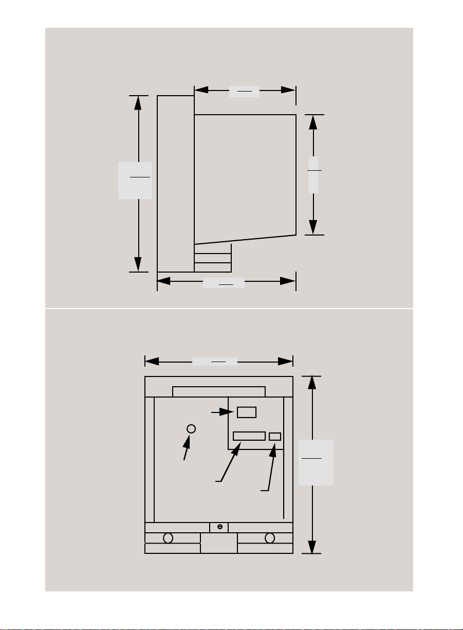
OUTLINE DRAWING
Side View
5.5
140
8.55
217
Rear View
AC Power
Pressure Port
RS-232 I/O
6.0
152
7.2
183
7.5
191
oo
8.55
217
On/Off
(Battery Only)
iv
Page 7

Section One
INSTALLING THE MODEL 370
The Setra Digital PressureGauge, Model 370, is a highly accurate pressure measurement system utilizing the patented SETRACERAM sensor, advanced microcomputer based electronics, and sophisticated firmware, resulting in a 0.02% FS
system accuracy.
The unusual ergonomic design of the Model 370 allows it to be used as a bench top
instrument (with keypad and display at the proper angle for viewing), as a portable
device with a built in carry handle, or as a rack mount instrument with the optional
19" rack mount kit.
SETUP
Connect the pressure gauge to an AC outlet by inserting one end of the provided
power cord into the back of the gauge, and the other end of the cord to the AC outlet.
The gauge will operate at any voltage from 100 to 240 VAC, 50 or 60 Hz. Once you
have plugged your gauge into a live outlet, it is automatically on.
The gauge uses very little power, and may be left connected permanently.
If you have the optional battery, refer to Appendix IV concerning battery power and
automatic recharging.
DISPLAY TEST
When your gauge is first powered on, it automatically performs a display test, showing all possible display segments. This test lasts approximately six seconds. The
gauge next displays "HELLO" and performs self-diagnostics to ensure proper
operation. The gauge then counts down to zero, and is ready for use.
PRESSURE CONNECTIONS
The Model 370 provides a standard 1/8" NPT female pipe thread pressure port with
filter, for connection to a variety of available fittings. The pressure gauge is rated for
clean dry gas (nonconductive/noncorrosive).
The Proof Pressure of the Model 370 (the maximum pressure which can be applied
without disturbing the calibration of the gauge) is 150% of the full scale pressure. To
ensure that the pressure applied to the gauge does not exceed the proof pressure,
properly rated relief valves should be installed in any system this gauge is connected
to.
That's all there is to installation. It is important that you read this User's Guide
thoroughly to ensure proper use of the gauge. The summary of Functions in the next
Section serves as a handy reference.
1
Page 8
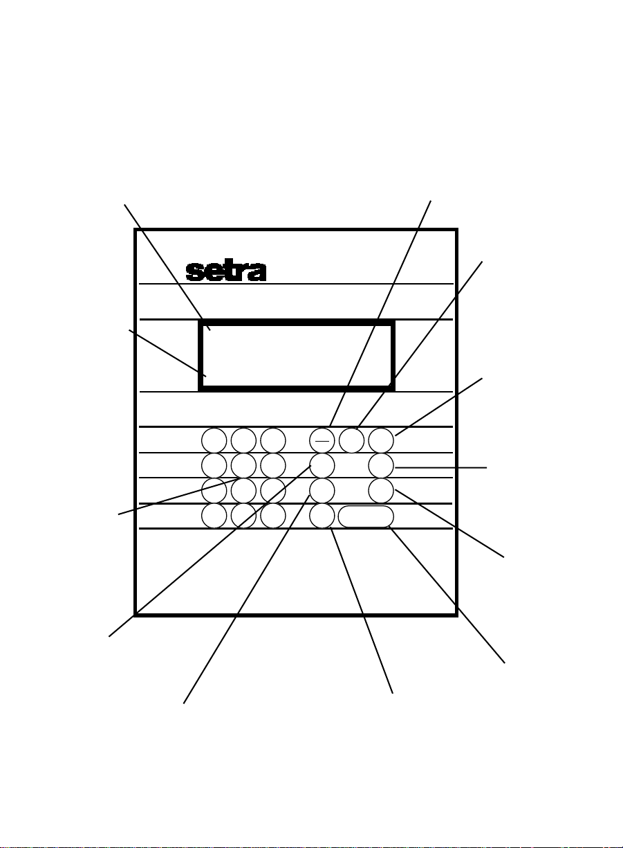
Portability and Accuracy
Right Where You Need It
6 digit LCD with Annunciators for
Display
Alarms, Min/Max values and
Engineering Units.
O.K.
User Program-
mable Indication
of Pressure Signal
Stability.
Keypad
Numeric keypad for
Entry of Custom
Conversion Factors,
Setpoints and
Calibration Data.
Digital Pressure Gage
SEA
LEVEL
-888888
O.K.
HI LO ALARM
7 8 9
4 5 6
1 2 3
.
-
0
Tracks Minimum and Maximum
units ft
mmbar
in hg
H2O PSI
f(p)
clear
set
points
min
max
set up zero
print span
conv
min/max
Values Encountered.
f(p)
Programmable Non-
Linear Function Key for
Barometric Ranges.
Converts True Baromet-
ric Pressure To Sea
Level Pressure.
set points
Hi/Lo Alarms-User Defined.
Alarm Indications are
Display Flashing, Audible
Tone and Message Sent
Out I/O Port.
zero
Dual Function Key
Operates as Tare or
with SetUp key as
Zero Calibration.
span
Use with SetUp
Key for Full Scale
Calibration.
set up
Program Custom
Functions and
Perform
Recalibration.
Sends Display Data Through a
Bidirectional RS-232 I/O Port. Programmable for Continous or Interval Printing,
print
300-9600 Baud Rate.
Exits Programming Mode To
clear
Normal Operation.
conv
Automatic Engineering Units
Conversion for Pressure and
Altitude. Predefined Units are
hPa, PSI, mbar, mmHg, inHg,
mmH2O, inH2O, ft, m, units.
2
Page 9
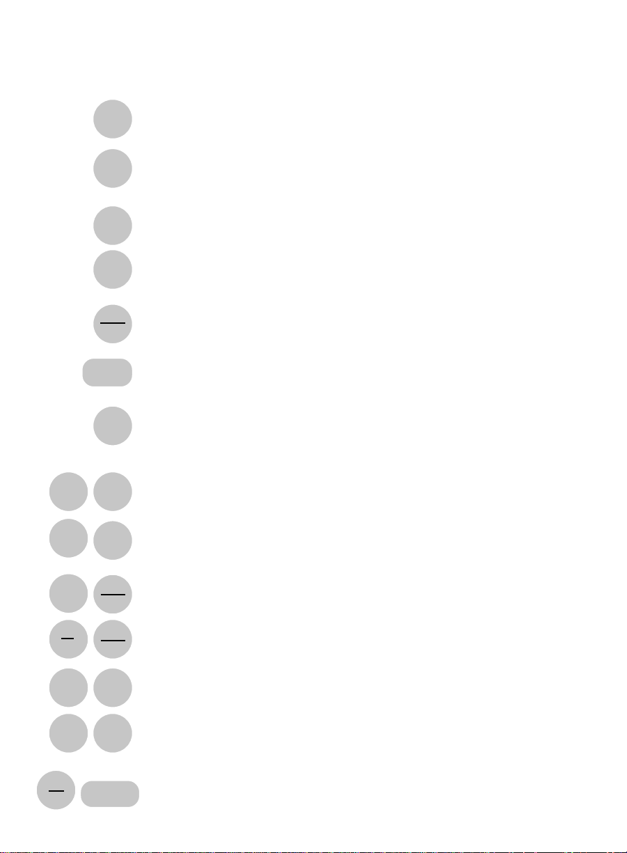
2.1 KEYBOARD FUNCTIONS
Section Two
SUMMARY OF FUNCTIONS
setup
print
conv
set
points
zero
min
max
clear
f(p)
print
Send information to a printer or other peripheral.
Convert engineering units being displayed.
Display HI and Lo Alarm setpoints.
Enter relative or absolute tare value.
Display minimum and maximum value encountered.
Clear the number or key sequence being entered or displayed.
Convert true pressure to SEA-LEVEL pressure (absolute pressure).
Send status summary to a printer or other peripheral.
setup
setup
setup
setup
set
points
min
max
min
max
zero
span
clear
Change Hi and Lo Alarm setpoints.
Enter MIN/MAX tracking mode.
Exit MIN/MAX tracking mode.
Perform ZERO calibration procedure.
Perform SPAN calibration procedure.
Clear the display, turn off MIN/MAX, clear the tare value, convert
to display the units the gauge was calibrated in.
3
Page 10

2.2 DISPLAY SYMBOLS
OK
hPa
PSI
inHg
mbar
mmHg
inH2O
mmH2O
ft
m
SEALEVEL
units
HI ALARM
The readings are within the user defined stability requirement.
The reading shown is given in hectopascals.
The reading shown is given in pounds per square inch.
The reading shown is given in inches of mercury.
The reading shown is given in millibars.
The reading shown is given in millimeters of mercury.
The reading shown is given in inches of water.
The reading shown is given in millimeters of water.
The reading shown is given in feet of altitude.
The reading shown is given in meters of altitude.
The reading shown is corrected to sea level.
The reading shown is given in user-defined pressure units.
The reading shown exceeds the HI setpoint.
LO ALARM
HI
LO
The reading shown exceeds the LO setpoint.
The reading shown is the maximum value encountered.
The reading shown is the minimum value encountered.
4
Page 11

2.3 DISPLAY MESSAGES
UnAbLE
The gauge is unable to execute the requested function in its
current configuration. Clear the display and continue.
OFLO
The display is over-ranged because excess pressure is applied
or because the user-defined conversion exceeds the number of
digits available in the display.
FLASHING
DISPLAY
BUSY
The pressure applied exceeds the rated range of the sensor.
The gauge is acquiring a stable reading.
Other messages which are displayed in the course of using the various functions of
the Model 370 are explained in the sections of the manual concerning those functions.
5
Page 12

6
Page 13

Section Three
DIGITAL PRESSURE GAUGE FUNCTIONS
3.1 ENTERING A NUMBER OR FUNCTION
To enter a number or function, simply press the key or keys which
correspond to the numbers or functions you wish to enter.
3.2 CLEARING A NUMBER OR FUNCTION
To clear a function or number you have begun to enter, press the CLEAR
key. This automatically returns the gauge to display mode, without affecting
any other functions which may be in use.
To reset the Model 370 to its power up condition, press "-", then CLEAR.
This clears the zero/tare value, shuts off MIN/MAX, and converts back to
the original engineering units. All of these functions are described in later
sections of this guide.
3.3 IF YOU MAKE A MISTAKE
If you mis-enter a number or enter a number or function the gauge cannot
accept, the display will read "UnAbLE". Press CLEAR to resume normal
display, and re-enter the number or function.
7
Page 14

3.4 CONVERTING ENGINEERING UNITS
The Model 370 will measure pressure in any engineering units, including six
built-in pressure conversions, two built-in altitude conversions, and a
user definable conversion.
To convert from one unit to another, simply press the CONV key repeatedly
until the units you want are in the display. The order of units is as follows:
hPa - PSI - mbar - mmHg - inHg - mmH2O - inH2O - ft - m - units. To return
directly to the units the gauge was calibrated in, press "-" then CONV.
See Section 4.1 for instructions on the use of user-defined units ("units"),
or Section 5 for displaying altitude.
3.5 TRACKING MIN AND MAX VALUES
To use the Model 370 to track the minimum and maximum pressures applied to
the sensor, enter the tracking mode by pressing SETUP, then MIN/MAX.
To examine the values stored, press MIN/MAX. The gauge will display "HI"
and the maximum value encountered for about three seconds, then will
display "LO" and the minimum value encountered for about three seconds,
and then will revert to normal display.
To shut off the min/max tracking mode, press "-", then MIN/MAX.
If the MIN/MAX key is pressed without having first entered the MIN/MAX
tracking mode as described above, the display will read "UnAbLE". Press
CLEAR and then follow the above procedure.
8
Page 15

3.6 SETTING AND USING ALARM SETPOINTS
The Model 370 has an alarm capability which will indicate when the pressure
applied has exceeded a high or a low setpoint. The annunciators are an
audible tone, a display message of "HI ALARM", and a message sent
through the communications port.
To examine the current value of the setpoints, press SETPOINTS. The
gauge will display "HI ALARM" and the high setpoint for about three
seconds, then will display "LO ALARM" and the low setpoint for about
three seconds, and then will revert to normal display.
To enter new setpoints, convert to the engineering units you wish to use,
and decide what values you will enter in the following procedure. Entering
a value which is too high or too low will cause the display to read "UnAbLE".
If this happens, press CLEAR to resume normal display mode.
1. Press SETUP, then SETPOINTS. The display will show "HI
ALARM" and the current high setpoint.
2. Now you can enter a new high setpoint by entering a number. To
keep the current setpoint without changing it, proceed to the next
step without entering a new number.
3. Press SETUP. The Model 370 will accept the number in the display
as the high setpoint, and immediately show "LO ALARM" and the
low setpoint.
4. Enter a new low setpoint, or to keep the current low setpoint, proceed
to the next step without entering a number.
5. Press SETUP. The number in the display will be accepted as the
low setpoint, and the gauge will revert to its normal display.
The factory setting for the high setpoint is 105% of the pressure range,
and the low setpoint is 5% below the pressure range. To effectively disable
the alarm setpoints, reset them to these values using the above procedure for
entering setpoints.
9
Page 16

3.7 USING THE TARE AND ZERO FUNCTION
The TARE function on the Model 370 gives you a way of setting the
displayed reading to zero or of subtracting a specified offset so that you
can monitor changes in pressure relative to a known starting point. This is
done by creating a tare value which will be subtracted before each updated reading is displayed.
To set the display to zero, press ZERO. The gauge will save the reading in
the display as the tare value, and will subtract that value from every subsequent reading before displaying it.
To subtract an offset from the display, enter the amount of the offset and
press ZERO.
To add an offset to the display, press "-", then enter the amount of the
offset and press ZERO.
To restore the normal display, press "-", then press ZERO. The gauge will
set the tare value to zero and resume displaying pressure in whatever
engineering units are selected.
If you enter a number which will result in a reading requiring more
digits than are available in the display, the display will show "OFLO".
Press CLEAR to resume normal display.
10
Page 17

3.8 PRINTING INFORMATION
Your Setra Digital Pressure Gauge is designed to print information when
connected to a printer, using the following procedure:
1. Set the printer up as described in its' manual.
2. Connect the RS-232 cable from the printer to the Model 370.
3. Make sure the printers on-line light is on.
4. Press PRINT to send the reading in the Model 370 display to the printer.
NOTE: When using a printer set the baud rate of the gauge to match that of
the printer (see Appendix I).
To interpret the meaning of the symbols printed, see Appendix III "RS-232 Serial Data Communications".
11
Page 18

3.9 REPETITIVE PRINTING
It is sometimes desirable to record pressure measurements at fixed
intervals of time. To print at fixed intervals, follow this procedure:
1. Connect a printer as outlined in Section 3.8.
2. Enter the number of seconds between readings.
3. Press PRINT. The gauge will print out a reading at the specified interval.
4. To cancel repetitive printing, press "-" then PRINT.
To interpret the meaning of the symbols printed, see Appendix III - "RS-232C
Serial Data Communications."
Most printers are equipped with a buffer which allows them to receive information
at high speed from the gauge, and print it at the slower speed of the printer.
Using repetitive print mode with a printer which is not equipped with a buffer
may cause a "Q-OFLO" message to be printed, indicating that the printer
cannot accept information at the rate it is being sent. There are three solutions
to this problem; either make the repetitive print interval longer, use a printer
equipped with a buffer, or set the communications baud rate on both the gauge
and the printer as slow as possible (300 baud, for instance).
12
Page 19

3.10 PRINTING SYSTEM STATUS
To get a summary of the condition of all active functions, press SETUP, then
press PRINT. A sequence of information will be printed indicating the range of
the gauge and the status of any functions which are currently in use, as shown
in this example.
STATUS
ELEV: 256 FT
MAX: 14.4193 PSI
MIN: 14.5188 PSI
HI ALARM: 15.8000 PSI
LO ALARM: 11.0000 PSI
ZERO: 1.0000 PSI
UNIT: 689.47 PSI
The actual messages will vary depending on which functions are in use.
3.11 INTERFACING WITH A COMPUTER
Your Setra Digital Pressure Gauge is designed to interface with a wide
variety of computers. If your gauge is connected to a computer, you can
transmit information to the computer using the simple procedure given for
"Printing Information."
For more advanced and versatile print functions, see Appendix III - "RS-232
Serial Data Communications."
13
Page 20

14
Page 21

ADVANCED PRESSURE GAUGE FUNCTIONS
4.1 USER DEFINED ENGINEERING UNITS
The Setra Digital Pressure Gauge has several built-in engineering units
conversions which are accessed simply by pressing CONV. If you want to
display pressure in units other than those provided, use the following
procedure.
Units can be directly changed by entering a factor (number to multiply by)
or a divisor (number to divide by) and will be indicated in the display by "units".
1. Calculate the ratio you wish to enter. If your ratio is in the form of PSI
per "UNITS", inHg per "UNITS", mbar per "UNITS", etc., you will enter a
divisor. Proceed with steps 2 through 5.
2. Press CONV until the display reads in the known units from which you wish
to convert.
3. If you are entering a divisor, press "-". If you are entering a factor, proceed
to step 4.
4. Enter the conversion ratio.
Section Four
5. Press CONV. The gauge is now displaying pressure in the unit specified
by the conversion ratio, and the "units" symbol.
The conversion ratio will be saved and used for the user-definable
engineering units until you enter a new ratio, even if the power is shut off
and turned back on.
To convert back to the built-in engineering units, press "-", then CONV.
When you execute this function through the RS-232 port instead of the
keyboard, you can specify the symbol for the engineering units which will be
reported through the port in response to the PRINT command.
1. If the ratio is a divisor, transmit the minus symbol, "-". If you are entering a
factor, proceed to step 2.
15
Page 22

2. the conversion ratio;
3. the command U, for CONVERT UNITS;
4. any combination of 5 alphanumeric characters, including spaces, to
identify the engineering units.
For example, if the transducer is currently reporting in PSI and the desired
units are grams per square centimeter the ratio is 70.307g/cm2 per psi (a
multiplier. Transmit:
70307Ug/cm2
the 370 will now report in g/cm2 to an interrogation. The conversion ratio
will be saved and used for the user definable engineering units until a new
ratio is entered, even if the power is shut off and turned back on.
16
Page 23

4.2 DIGITAL ALTIMETER SETTING INDICATOR
The Model 370 may be used to display corrected sea-level pressure by
"reducing" true barometric pressure at a known elevation to what the pressure
would be at sea-level at the same latitude and longitude.
This function is only available on gauges with barometric or absolute pressure
sensors.
Before using the "SEA LEVEL" correction mode, you must first determine and
enter the station elevation, which is the altitude above sea level at which the
gauge is installed.
1. Press CONV until the gauge is displaying pressure units (make sure it is not
displaying in "ft" or "meters").
2. Press "-", then Clear to make sure the tare/zero registers are empty.
3. Press SETUP, then press f(p). The display will read "CAL FP".
4. Enter the station elevation and press SETUP. The display will read
"units ft".
5. Press CONV to select the units of elevation, either "ft" or "meters".
6. Press SETUP. The gauge will accept the station elevation and display
"SEA LEVEL" corrected pressure.
Once you have entered that station elevation, you can switch quickly and easily
from true barometric pressure to corrected sea level pressure and back by
pressing f(p).
The terms "Station Elevation" and "Reduction of Pressure" have very specific
meanings in the jargon of Altimeter Setting Indicators and the actual
calculations performed by the Model 370 are fairly complex. For further details,
consult: "Smithsonian Meteorological Tables, Vol. 114", NACA Report #1235,
or contact a Setra Applications Engineer.
NOTE: When the f(p) key is pressed in order to begin displaying pressure
corrected to sea level, the zero/tare value described in Section 3.7 is cleared
automatically to assure that absolute sea level pressure is displayed.
17
Page 24

18
Page 25

Section Five
DISPLAYING ALTITUDE
The Model 370 Digital Pressure Gauge can be used to display a variety of
altitude measurements. It may be used as an altimeter calibrator, a standard
altimeter, a true corrected altimeter (self corrected or remote), or as a relative
altimeter. It may be used to indicate small relative changes in altitude
through the use of the zero/tare function.
This function is only available on gauges having absolute or barometric
pressure sensors.
5.1 ALTIMETER CALIBRATOR, STANDARD ALTIMETER
To indicate standard altitude with the Model 370, follow this procedure.
1. Clear the zero/tare register by pressing "-" then ZERO.
2. If the display is in "SEA LEVEL" press f(p) so that it is not in
sea level mode.
3. Press CONV until the display is in "feet" or "meters".
The gauge is now displaying altitude as a function of the Standard Atmosphere
Curve. For a copy of the data which describes the Standard Atmosphere,
consult: NACA Report 1235, or "Smithsonian Meteorological Tables, Vol. 114".
Note: This display of standard altitude will not coincide with the actual
elevation. See the next section, "Displaying True Altitude" in this guide.
19
Page 26

5.2 DISPLAYING TRUE ALTITUDE
The Model 370 can function as an altimeter displaying true altitude by
correcting the above Standard Atmosphere conversion for the local barometric
pressure. This correction can be setup two ways.
If you are starting at a known station elevation, use the following procedure:
1. Press CONV until the gage is displaying pressure units (make sure not to
select "ft" or "meters").
2. Press SETUP, then press the f(p) key. The display will read "CAL FP".
3. Enter the station elevation and press SETUP. The display will read
"units ft".
4. Press CONV to select the desired units of elevation, either "ft" or "meters".
5. Press SETUP. The gage will accept the station elevation and display
"SEA LEVEL" corrected pressure (as in Section 4.2).
6. Press the ZERO key. The display indicates the difference between the
current pressure and the sea level pressure.
7. Press the CONV key until the desired altitude units (ft or meters) appear in
the display. The display will now indicate the true altitude above sea level.
8. The gage is now functioning as a corrected altimeter, and will indicate true
altitude as it is moved from one location to another.
CAUTION: In any true altimetry application, the accuracy of the measurement is dependent on the quality of the correction made for local barometric
pressure.
Barometric pressure changes often, and so the reading will drift over time as
the sea level corrected pressure drifts. To recalibrate the true altimeter, repeat
the above procedure at a known starting elevation often.
20
Page 27

If you are not at a known elevation, the gauge may be used in true
altimeter mode by obtaining an Altimeter Setting Indication (sea level
corrected pressure) from a local airport or weather station, and following
this procedure:
1. Press the CONV key until the engineering units of the known sea level
pressure appears in the display.
2. Enter the known sea level pressure and press ZERO. The difference
between the sea level pressure and the current pressure is displayed.
3. Press CONV until the desired altitude units of measure are displayed.
4. The gauge is now functioning as a corrected altimeter, and will display
true altitude as it is moved from one location to another.
CAUTION: In any true altimetry application, the accuracy of the measurement
is dependent on the quality of the correction made for local barometric pressure.
Distance from the reporting station and elapsed time from the measurement will
greatly affect the accuracy of the altitude measurement as barometric pressure
changes. Repeat the above procedure as often as new ASI data is available.
21
Page 28

5.3 MEASURING RELATIVE ALTITUDE
To measure relative altitude in either Standard or True Altimeter Mode, a
reference altitude may be established by setting the displayed reading to
zero, or by offsetting it by a specified amount entered as a tare value.
1. Use one of the above procedures to display either Standard or True
Altitude.
2. To set the displayed reading to zero, press ZERO.
3. To subtract an offset from the display, enter the amount of the offset and
press ZERO.
4. To add an offset to the display, press "-", then enter the amount of the
offset and press ZERO.
5. The gauge is now displaying altitude relative to the reference point, and will
indicate changes in altitude as it is moved from one location to another.
CAUTION: In any true altimetry application, the accuracy of the measurement
is dependent on the quality of the correction made for local barometric pressure.
Barometric pressure changes often, and so the reading will drift with time as
the sea level corrected pressure drifts. To compensate for this effect, repeat
the above procedures often.
22
Page 29

SETUP FUNCTIONS
I.1 FORMATTING BAUD RATE
The Setra Digital Pressure Gauge is capable of interfacing with a wide variety of
computers or other devices through the RS-232 serial communications port.
Devices which are connected this way must be set up to communicate at the
same rate of speed.
To change the baud rate of the gauge (the rate at which the gauge sends information out through the port) so it agrees with that of the device connected to it,
use the following procedure.
1. Press CONV until the gauge is displaying pressure units (make sure it is not
displaying in "ft" or "meters").
2. Press the "-" key.
3. Enter "5555". This is the baud rate access code.
4. Press SETUP. The display will read "CAL br".
5. Enter the baud rate. Choose either 300, 600, 1200, 1800, 2400, 3600, 4800
or 9600.
Appendix I
6. Press SETUP.
The baud rate is factory set to 2400. If you change the baud rate and wish the
gauge to retain the new rate after power is removed and restored, repeat steps
2-6 a second time.
23
Page 30

I.2 DISABLING THE BEEPER
The gauge emits a tone to verify the entry of a number or function. To disable
the tone for silent operation, use the following procedure:
1. Press CONV until the gauge is displaying pressure units (make sure it is
not displaying in "ft" or "meters").
2. Press the "-" key.
3. Enter "9999". This is the beeper access code.
4. Press SETUP. The beeper is disabled.
To reactivate the beeper, repeat Steps 2-4.
I.3 STABILITY INDICATOR
The "OK" symbol is an indication of the stability of the pressure being applied
to the sensor. "OK" is displayed whenever the pressure is changing by less
than the Stability Indicator Limit from the last display update to the next.
The Stability Indicator Limit may be used when the Model 370 is serving as a
Secondary Pressure Standard, to ensure that calibration pressures being
applied to another device are accurate and stable within a given amount. For
example, to indicate whether a pressure of 15 PSI is stable to within ±0.1 PSI,
the Stability Indicator Limit would be set to 0.1 PSI.
To change the Stability Indicator Limit, use the following procedure:
1. Press CONV until the gauge is displaying pressure units (make sure it is
not displaying in "ft" or "meters").
2. Press CONV until the gauge is displaying the desired engineering units.
3. Press the "-" key.
4. Enter "1111". This is the Stability Indicator access code.
5. Press SETUP. The display will read "CAL Sb"
6. Enter the stability requirement in the specified engineering units and press
SETUP. The gauge will return to normal display, using the newly entered
stability requirement as the criterion for displaying the "OK" symbol.
The stability requirement will remain in place until it is modified again, even if
the power is removed and restored to the gauge.
24
Page 31

I.4 OMITTING ENGINEERING UNITS
Some applications may require frequent switching from one engineering
unit to another. The Model 370 can be setup to omit one or more of the
built-in engineering units to reduce the number of times CONV must be
pressed to get from one unit of measure to the next.
1. Press CONV until the gauge is displaying pressure units
(make sure it is not displaying in "ft" or "meters").
2. Press the "-" key.
3. Enter "2222". This is the Engineering Units access code.
4. Press SETUP. The display will read "CAL U".
5. Press SETUP. The display will read "1 or 0 units".
6. Enter "1" if you wish to include "units" (the user definable unit of
measure) or "0" if you wish to omit it.
7. Press SETUP. The display will read "1 or 0 hPA".
8. Enter "1" if you wish to include "hPa" or "0" if you do not.
9. Press SETUP.
10. Repeat steps 6 & 7 until all units have been selected or omitted.
If is necessary for at least one pressure unit to be used. If no units of measure
are selected, the gauge will display "UnAbLE". Press CLEAR and start over.
I.5 SOFTWARE REVISION NUMBER
To check the software revision number, use this procedure:
1. Press CONV until the gauge is displaying pressure units (make sure it is
not displaying in "ft" or "meters").
2. Press the "-" key.
3. Enter "7777" and press SETUP.
4. The display will read "rEF" and the revision reference number of the
system software. Press CLEAR to restore normal display mode.
25
Page 32

I.6 SELF DIAGNOSTICS
The Model 370 has a built-in self diagnostic procedure. This procedure
prompts an operator to verify that the gauge is fully operational, (but does not
verify proper calibration), by checking the keyboard, the keyboard decoder, the
display, and a checksum test on internal memory.
1. Press CONV until the gauge is displaying pressure units (make sure it is
not displaying in "ft" or "meters").
2. Press the "-" key.
3. Enter "8888". This is the Diagnostic access code.
4. Press SETUP. The display will read "d-noS".
5. Press SETUP. The display should read "do CLr".
6. Press CLEAR. The display should read "do CON".
7. Press CONV. The display should read "do FP".
8. Press F(p). The display should read "do 3".
9. Press "3". The display should read "do 4".
10. Press "4". The display should read "do 8".
11. Press "8". The display should read "bUSY".
12. Wait until the display reads "PASS".
13. Press SETUP. All segments of the display should be lit.
14. Press SETUP and wait a few seconds. The gauge should perform its power-
up internal self test and return to normal display mode.
In the unlikely event that an error message appears, repeat the test procedure
to determine that the proper key was pressed for each prompt. To restart the
test procedure after an error message has been displayed, power to the gauge
must be turned off and back on. If the last diagnostics routine performed was
not completed successfully, the gauge will automatically return to the "d-noS"
prompt, and the above procedure should be executed starting at Step 5.
If a problem persists, contact a Setra Applications Engineer for assistance.
26
Page 33

CALIBRATION
The zero and span of the Model 370 Digital Pressure Gauge may be calibrated
using the following procedures. A high accuracy primary pressure standard is
recommended as the calibration source, since the high accuracy of the Model
370 will be adversely affected if the calibration pressure is not of equal or
greater accuracy.
The calibration procedure will require the same pressures, in the same
engineering units (usually PSI), as were originally calibrated at the factory.
During calibration, note that the gauge will display a prompt message, not the
actual pressure applied, and cannot be used to monitor the pressure input
during the calibration procedure.
II.1 ZERO CALIBRATION
1. Make certain the gauge is in a stable temperature environment for several
hours before calibration.
2. Press SETUP, then press ZERO. The display will read "APPLY" and the
pressure required for zero calibration.
Appendix II
3. Apply the indicated pressure from a high accuracy standard.
4. Press SETUP. The gauge will take data, adjust its zero calibration, and
return to normal display mode.
If the new zero data is too far from the factory calibration, the gauge will display
"UnAbLE". Verify the applied pressure. If it is correct, contact a Setra Applications Engineer for assistance.
27
Page 34

lI.2 SPAN CALIBRATION
To perform the span calibration on the Model 370, it is necessary to apply both the
zero and the full scale pressures, as in the following procedure:
1. Make certain the gauge is in a stable temperature environment for several
hours before calibration.
2. Press SETUP, then press SPAN. The display will read "APPLY" and the
pressure required for
3. Apply the indicated pressure from a high accuracy standard.
4. Press SETUP. The display will read "APPLY" and the pressure required for
full scale
5. Apply the indicated pressure from a high accuracy standard.
6. Press SETUP. The gauge will take data, adjust its' zero and span calibra-
tions, and return to normal display mode.
If the new zero and full scale data is too far from the factory calibration, the gauge will
display "UnAbLE". Verify the applied pressures. If they are correct, contact a Setra
Applications Engineer for assistance.
calibration.
zero
calibration.
28
Page 35

Appendix III
RS-232 SERIAL DATA COMMUNICATIONS
The Setra Model 370 Digital Pressure Gauge is equipped with a bidirectional RS-232
interface which allows communications between the gauge and other devices which
are also equipped with an RS-232 interface.
This section provides detailed technical information showing how to operate the
Model 370 remotely from a computer.
To perform printing operations to a serial printer, Section 3.7 "Printing Information"
and Appendix I.2 "Formatting Baud Rate" provide the necessary information.
III.1 INTERFACING THE MODEL 370 TO A COMPUTER
The bidirectional serial interface allows the gauge to transmit information to a
printer, computer, or terminal. It also allows the computer or terminal to send
commands to the gauge, duplicating the functions of the front keypad.
Any computer or terminal with an RS-232 serial port can be connected to
the gauge. The baud rates of the gauge and the computer must be set
identically. (see Appendix I.2 - "Formatting Baud Rate").
29
Page 36

III.2 SENDING COMMANDS TO THE GAUGE
All the functions of the Model 370 may be executed by sending the appropriate
command from the computer to the gauge. The commands are standard
alphabetic characters which correspond to keys on the front keypad of the
gauge. The table below also lists the ASCII and hexadecimal values of the
codes for those interested in more technical programming.
FUNCTION CODE ASCII HEX FUNCTION CODE ASCII HEX
Setup S 83 $53 0 0 48 $30
Clear C 67 $43 1 1 49 $31
Conv U 85 $55 2 2 50 $32
Min/Max M 77 $4D 3 3 51 $33
F(p) B 66 $42 4 4 52 $34
Setpoints A 65 $41 5 5 53 $35
Zero Z 90 $5A 6 6 54 $36
Span F 70 $46 7 7 55 $37
Print P 80 $50 8 8 56 $38
45 $2D 9 9 57 $39
..46 $2E
Verify V 86 $56
To execute a command, send the appropriate character code from the
terminal or computer to the pressure gauge.
For example, to interrogate the gauge for a pressure reading, send from a
terminal (or create a computer program which will send) the letter "P" through a
serial port to the gauge. The gauge will receive the "P" and execute the print
function. That is, it will transmit the reading in the display through its serial port
back to the computer or terminal.
It is not necessary to transmit a carriage return or line feed character to the
gauge after a command character.
30
Page 37

III.3
RECEIVING DATA FROM THE GAUGE
There are several types of messages which the gauge may send in response
to the various commands.
The immediate response to the PRINT command interrogation is the most
common message. It is a string of characters consisting of the reading on the
display and other information.
The format of that string of characters is shown below:
+ 1 2 3 . 4 5 6 units A OK SEA LEVEL cr lf
G
T
The first character is the sign, next are 7 digits (including the decimal point)
followed by a blank space. Next are six characters, including some spaces,
which signify the engineering units, followed by another space, the symbol
indicating (A)bsolute, (G)auge, or (T)ared pressure, and another space. This
is optionally followed by the OK symbol (if the OK symbol on the display is on),
and optionally followed by SEA LEVEL if in sea level correction mode. The
string is ended with a carriage return and line feed character.
Other potential messages are "UnAbLE", "SET-UP", and "CAL" appearing
in response to the various functions and situations described in other sections
of this guide. See Section 3.10 for an example of the system status message
sent in response to SETUP PRINT.
31
Page 38

III.4 IMMEDIATE AND REPETITIVE PRINT MODES
Two print modes are available on the Model 370, as discussed in Sections
3.8 and 3.9.
The immediate print interrogation, used in the example above, is the
preferred method of getting pressure data to a computer program.
The repetitive print mode is intended for sending data to a printer or data
logger at a time interval which is user definable (Section 3.9).
III.5 VERIFY FUNCTION
To identify the Setra Digital Pressure Gauge when it is connected remotely
to a computer, send the command character "V" (for verify). The gauge will
respond with a message like the one shown below .
SETRA DIGITAL PRESSURE GAUGE MODEL 370
11.0000 TO 16.0000 PSI A
III.6 STATUS AFTER POWER IS APPLIED
The Setra Digital Pressure Gauge has an internal nonvolatile memory for
storing certain status and calibration information. This memory is not erased
when power is removed from the unit. All setup functions (such as baud rate
and alarm setpoints) and user conversion factors are stored in the memory,
so that once they are setup, they do not need to be setup again unless you
wish to change the configuration.
Some of the functions default to "not in use" when the power is turned on;
MIN/MAX tracking will be off, the zero/tare value will be zero, and the f(p)
function will be off.
During the first thirty seconds of operation, the gauge will execute an internal
self-diagnostic procedure. When the gauge is ready for use, it will transmit
the "Verify" message shown above.
32
Page 39

III.7 RS-232 INTERFACE HARDWARE
The RS-232 Communication Standard describes in detail the requirements
and conventions of RS-232. For most applications, the information given here
is sufficient to solve any problems.
The Setra Digital Pressure Gauge implements the majority of the RS-232
communications standards, but does not provide handshaking lines (such as
busy, DSR, or DTR).
The four lines which must be connected are diagrammed below, along with
the pin layout of the female connector on the back of the gauge.
13 7 3 2 1 PIN DESC.
O O O O O O O O O O O O O 1 Protective ground
O O O O O O O O O O O O 2 Input to gauge (RXD)
25 14 3 Output from gauge (TXD)
7 Signal ground
The Model 370 serial interface is a DCE (Data Communications Equipment)
type, with a standard female DB25S pin connector. This means that it receives
data on pin 2 and sends data on pin 3. This is in contrast to DTE (Data Trans
mission Equipment) which receives data on pin 3 and sends data on pin 2. The
RS-232 standard describes communications between DTE and DCE devices.
Since many computers have serial ports configured as DTE, the Model 370
conveniently plugs directly into the standard serial port on most computers,
using a standard RS-232 "straight-through" cable available from SETRA, or
from any computer hardware vendor.
Some devices, including some printers and computers, will be equipped
with DCE interfaces like that in the Model 370. To connect the Model 370 to
these devices, a "null modem" cable is required. This is simply a cable which
connects pin 2 and 3 of the Model 370 to pin 3 and 2 of the other device
respectively by crossing them in the cable. This kind of cable is also available
from SETRA, or from any computer hardware vendor.
The maximum recommended cable length is 15 meters.
The RS-232 data format used by the Model 370 is :
8 bits
1 start bit
1 stop bit
no parity.
For more information, consult RS Standard RS-232, or contact a SETRA
Applications Engineer.
33
Page 40

34
Page 41

Appendix IV
ACCESSORIES AND OPTIONS
IV.1 BATTERY / RECHARGER OPTION
The Model 370 Digital Pressure Gauge can be operated as a portable
instrument with the battery/recharger option. The battery option is
designed to allow a standard 8 hour workshift, followed by a 16 hour
recharge cycle.
The battery option is a rechargeable 12 VDC Nicad battery, and an
automatic internal battery charger which functions whenever the gauge is
plugged into an AC outlet. Also included in the battery option are an on/off
switch and the required internal wiring.
OPERATION
The battery is shipped from the factory in a low charge condition. Before
use, plug the gauge into AC power for 16-24 hours to allow a complete
charge of the battery to take place.
The high capacity Nicad batteries are rated for more than 1,000 charge/dis
charge cycles. As with any Nicad, the life and performance of the battery pack
can be extended by following the suggested usage guidelines, that is, allow the
battery to run and discharge for 8 continuous hours before recharging it for a
minimum of 16 hours.
The battery is automatically trickle charged whenever AC power is present.
There is no danger of overcharging the battery so no other precautions
are necessary.
Setra also offers replacement or spare battery packs and an external recharger
for applications where battery operation is desired for longer than 8 hours. A
battery pack may be externally charged and then placed in the gauge.
REPLACING THE BATTERY PACK
1. Disconnect the AC power cord.
2. Place the gauge face down on a clean flat surface.
3. Remove the 3 screws which hold the back cover in place and remove
the cover.
4. Do not remove any other screws, opening the sensor cavity will
affect calibration.
5. The battery is the block with the yellow plastic cover. Unplug its' cord
from the receptacle in the housing.
6. Remove the battery by lifting up and back (the battery is "L" shaped).
7. Replace the new battery by reversing the above steps.
35
Page 42

IV.2 IN CASE OF DIFFICULTY
If a problem persists which cannot be solved by reading the appropriate
sections of this manual, contact a SETRA Applications Engineer for assistance
at the toll free number: 1-800-257-3872
IV.3 OPTIONS
1. Internal rechargeable battery pack.
2. 19 inch rack mount kit.
36
Page 43

Pressure Ranges
Model 370 Specifications
Type of
Pressure Pressure Range Display Altitude Range
Barometric 600 to 1100 mbar 600.00 to 1100.00 -1000 to 13,800 ft.
800 to 1100 mbar 800.00 to 1100.00 -1000 to 6,400 ft.
Absolute 0 to 10 psia 10.0000 10,300 to 100,000 ft.
0 to 20 psia 20.0000 -1000 to 100,000 ft.
0 to 50 psia 50.0000 -1000 to 100,000 ft.
0 to 100 psia 100.000 -1000 to 100.000 ft.
Proof Pressure: 150% of full scale pressure range.
Pressure Media: Clean dry air or other gases (non-condensable).
Accuracy Data
Accuracy
2
±0.02%3 FS at 70°F (21°C)
Non-Linearity ±0.012% FS (End Point)
Hysteresis 0.010% FS
Non-Repeatability 0.010% FS
Thermal Effects
4
Compensated Range +32°F to 110°F (0 to +45°C)
Thermal Zero Shift ±0.002% FS/°F (0.004% FS/°C)
Thermal Sensitivity Shift ±0.001% FS/°F (0.002% FS/°C)
Altitude Resolution 1 ft. (4 ft. for 100 psi range)
Stability 0.005% FS, 24 hours
0.02% FS, 30 days
0.05% FS, 1 year
Output Data
Display 6 digit Liquid Crystal Display (LCD) with annunciators for
pressure/altitude engineering units (PSI, mbar, hPa, mmHg,
in.Hg, mmH2O, in.H2O, ft, m, units), HI/LO ALARM,
pressure signal stability (O.K.) and barometric pressure
corrected to sea level (SEA LEVEL).
Digital Output Bidirectional RS-232 interface. All display data can be
transmitted on the interface and all keyboard functions and
commands can be duplicated using a remote terminal or
keyboard.
Digial Interface Bidirectional RS-232 interface. Access data, functions, and
commands via an RS-232 compatible remote terminal data
acquisition system or data storage device. 300, 600, 1200, 2400,
4800, 9600 Baud Rate, adjustable.
Physical Data
Pressure Fitting 1/8" - 27 NPT internal.
Height 8.55 in./217 mm.
Width 7.5 in./191 mm.
Depth 7.2 in./183 mm.
Weight 12 lbs. with internal rechargeable battery pack
Power Cord 5 foot length, 3-prong grounding plug
Operating Power 110/220 VAC (-10% to +30%), 50/60 Hz., optional 12 VDC
internal rechargeable battery pack (approx. 8 hours
between charges). Approximately 4 watts power consumption.
Notes: 1. Altitude is calculated using a polynomial expression, which is derived from the standard
atmosphere curve, and corrected to sea level by the methods outlined in "Smithsonian
Meteorlogical Tables, Vole 114". Ranges greater than 20 psia not recommended for
altimeter certification.
2. RSS of Non-Linearity, Non-Repeatability and Hysteresis.
3. FS = 300 hPa/mb range; 500 hPa/mb for 600-1100 hPa/mb range
4. Unit calibrated at 70°F. Maximum thermal error is computed from this datum.
37
1
Page 44

38
Page 45

Appendix V
WARRANTY INFORMATION
V.1 LIMITED WARRANTY - PRESSURE PRODUCTS
SETRA warrants its products to the original consumer purchaser against
defects in materials and workmanship for a period of one year from the date
of sale by SETRA, as shown in its shipping documents, subject to the
following terms and conditions:
Without charge, SETRA will repair or replace products found to be defective
in materials or workmanship within the warranty period provided that:
a) the product has not been subject to abuse, neglect, accident, incorrect
wiring not our own, improper installation or servicing, or use in violation of
instructions furnished by SETRA;
b) as to any prior defects in materials or workmanship covered by this
warranty, the product has not been repaired or altered by anyone except
SETRA or its authorized service agencies;
c) the serial number or date code has not been removed, defaced or
otherwise changed.
d) examination discloses, in the judgement of SETRA, a defect in materials
or workmanship which developed under normal installation, use and service;
e) SETRA is notified in advance and approves the return, and the products
return, and the products returned to SETRA transportation prepaid.
Setra does not assume the costs of removal and/or installation of the
product or any other incidental costs which may arise as the result of any
defect in materials or workmanship nor will SETRA be liable for
consequential damages.
This warranty is in lieu of all other express warranties. Any warranty implied
by law, including warranties of merchantability or fitness, is in effect only for
the duration of the express warranties set forth above. No representative or
person is authorized to give any other warranty or to assume for SETRA any
other liability in connection with the sale of its products. SETRA will not be
liable for any consequential damages resulting from the use or installation of
its products.
38
Page 46

40
Page 47

39
Page 48

Published by:
Setra Systems, Inc.
159 Swanson Road, Boxborough, MA 01719
Telephone (800) 257-3872 or (978) 263-1400
Telefax (978) 264-0292
Web: www.setra.com
All Rights Reserved
SS0470 REV D 06/06
 Loading...