

Page 1
Setra Local Display
Model 328
Installation and Operating Instructions
1.0 INSTALLATION
Setra’s Model 328 is a small, local display designed for installation in high density modular block
gas sticks and panels. It can be used with voltage output and current output transducers using
15 Pin and 9 Pin D-Sub connectors. Consult Table 2, the Configurable Part Number Chart on
page 3, to determine the configuration that is supplied. For setting optimum viewing angle, the
328 display housing can rotate 360º degrees. A built-in positive stop limits the rotation of the
front portion to a maximum of 360º degrees. If resistance is encountered when trying to rotate
in one direction, rotate in the opposite direction.
2.0 ELECTRICAL CONNECTIONS
The 328 can be supplied with either a 15 Pin high-density or 9 Pin D-Sub connector to the input
transducer and to the power supply. Confirm the electrical connection supplied, and refer to the
appropriate column below for proper connections.
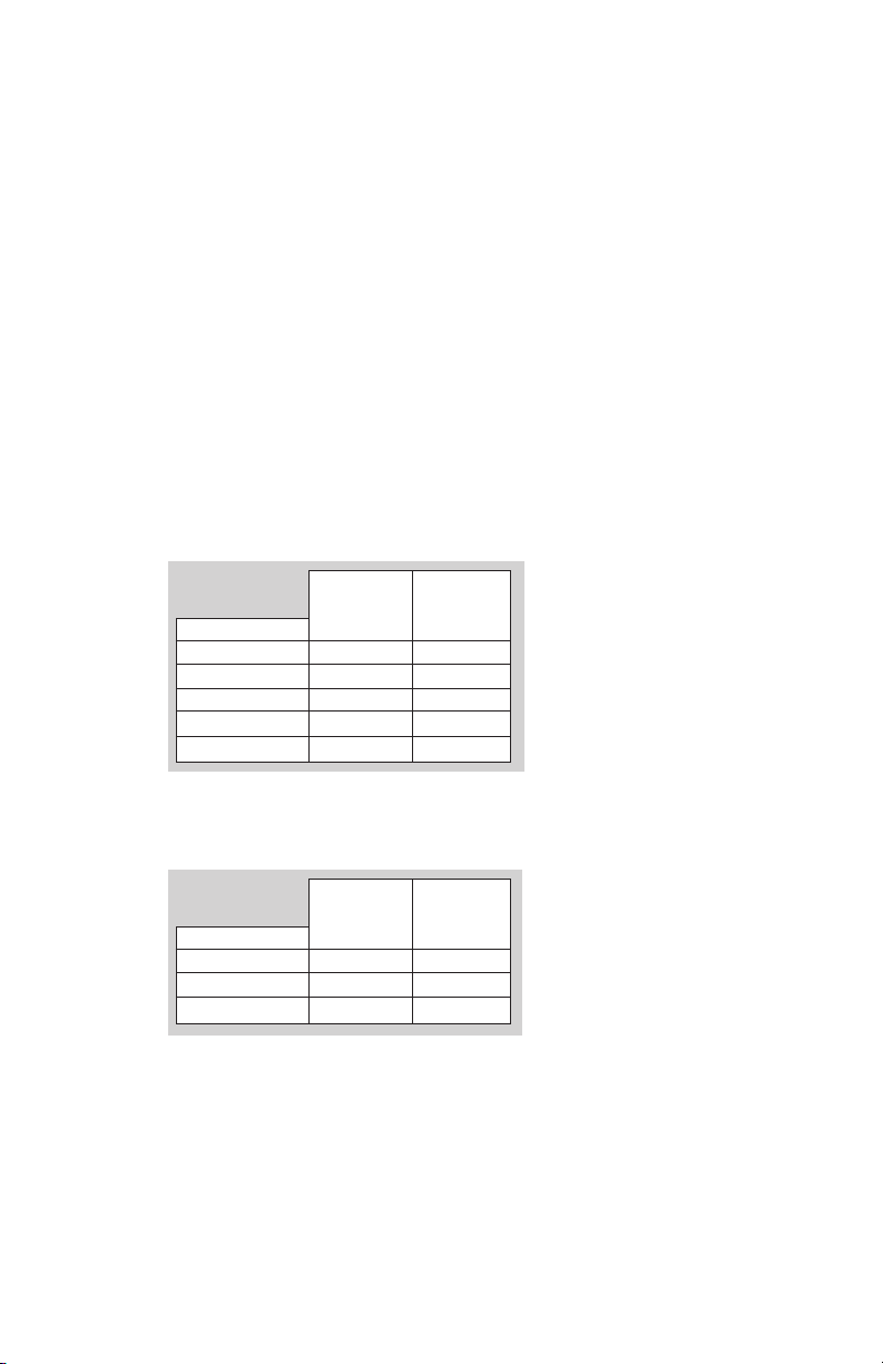
2.1 Voltage Units
2.2 Current Units
9 PIN 15 PIN
D-SUB D-SUB
CONNECTION PIN PIN
+ EXCITATION 4 7
+ OUTPUT 1 2
– OUTPUT 8 12
– EXCITATION 9 5
CASE GND SHELL SHELL
Reverse Polarity Protected.
9 PIN 15 PIN
D-SUB D-SUB
CONNECTION PIN PIN
+ EXCITATION 4 7
– EXCITATION 9 5
CASE GND SHELL SHELL
2.3 EMC Certification
This product complies with EMC Directive 2004/108/EC per EN61326-1 Electrical Equipment
for Measurement, Control and Laboratory use – EMC Requirements. In order to meet the EMC
requirements, the following conditions must be followed during installation:
1. Shielded cable must be used, and the shield must be tied to earth ground (not power
supply ground) on at least one end of the cable shield/drain wire. The shield must be
maintained all the way from sensor to the power supply.
2. If unshielded cable is used, an earth grounded metal conduit fitting can be used to
replace the shielded cable.
1
Page 2
3. For a sensor with a metal body or enclosure, the body/enclosure must be grounded to
earth. If a protective metal housing is used, the metal housing should be grounded to
earth
2.4 RoHS Compliance
The Model 328 complies with the European Union (EU) RoHS Standards for the elimination of
hazardous and non-environmentally friendly materials. The product is so marked as to designate its compliance only on its external packaging.
3.0 MECHANICAL INSTALLATIONS
The Model 328, with its rotating front face, requires the use of a locking pin to maintain rigid
installation with its mating transducer. This is accomplished by means of a locking pin on the
Model 328 display. This locking pin engages with a matching bracket/hole on the interfacing
transducer. This locking pin is replaceable should it become damaged during repeated installa-
tion events.
4.0 CALIBRATION
The 328 is factory calibrated to display engineering units. Setra recommends that the zero
adjustment be done using the transducer zero potentiometer, whenever possible. The display
zero should only be used for minor adjustments. Never adjust the span unless proper calibra-
tion equipment is used and proper calibration procedures are followed.
4.1 Auto Zero & Auto Span Adjustment
The auto zero and auto span adjustment buttons are located on the front of the unit just under
the digital display. See Table 1 for details of functionality.
1. AUTO ZERO: Apply zero pressure to the transducer and adjust the 328’s zero if
the 328 does not display ZERO reading accurately. Press and Hold the ZERO button and at
the same time press and hold the ENTER button for 2 to 3 seconds.
2. AUTO SPAN: Apply full scale pressure to the transducer and adjust the span on the 328. Press
and hold the UNITS button, and at the same time press and hold the ENTER button for 2 to 3
seconds. Make sure the display zero is accurate before adjusting auto span.
CAUTION: If you do not press the ENTER button within 5 seconds of pressing the UNITS but-
ton, the displayed units will change. (See section 4.3, page 3)
4.3 Pressure Units Change
The Model 328 is capable of changing the Pressure units by pressing and holding UNITS buttons
for 5 seconds An illuminated LED will light under the respective Pressure Unit (e.g., “PSI”, “Bar”,
or “KPa”). The unit conversion factors are pre-configured at the factory. Consult factory for re-
configuration when necessary.
4.4 Overflow/Underflow
The Model 328 will display an overflow or underflow condition by means of a visual indication.
When in Overflow condition, the Model 328 will exhibit an “OUF” on the LED display. When in
an Underflow condition, the
Model 328 will exhibit an “UDF” on the LED display.
5.0 SPECIFICATIONS
Display Voltage Input
Digits -1999 to 1999 -1999 to 1999
Type 7 Segment LED 7 Segment LED
Polarity Automatic (-) display Automatic (-) display
Long Term Stability ±0.25% Reading ±0.25% Reading
Accuracy 0.10% of reading ±1 count 0.10% of reading ±1 count
Environmental
Operating Temp. +32°F to +140°F (0°C to +60°C) +32°F to +140°F (0°C to +60°C)
Storage Temp. -4°F to +185°F (-20°C to +85°C) -4°F to +185°F (-20°C to +85°C)
Temp. Coeff. 100 ppm/C 100 ppm/C
Electrical Data
Current Input
Input Signal 0 to 5 VDC, 0 to 10 VDC 4-20 mA loop powered
Excitation 12 VDC to 30 VDC 6.5 VDC max voltage drop
1 meg ohm min input impedance
< 30 mA current consumption
Display Update Rate 25 updates/min. 25 updates/min
Protection Reverse polarity protection 100 mA current limit, reverse
polarity protection
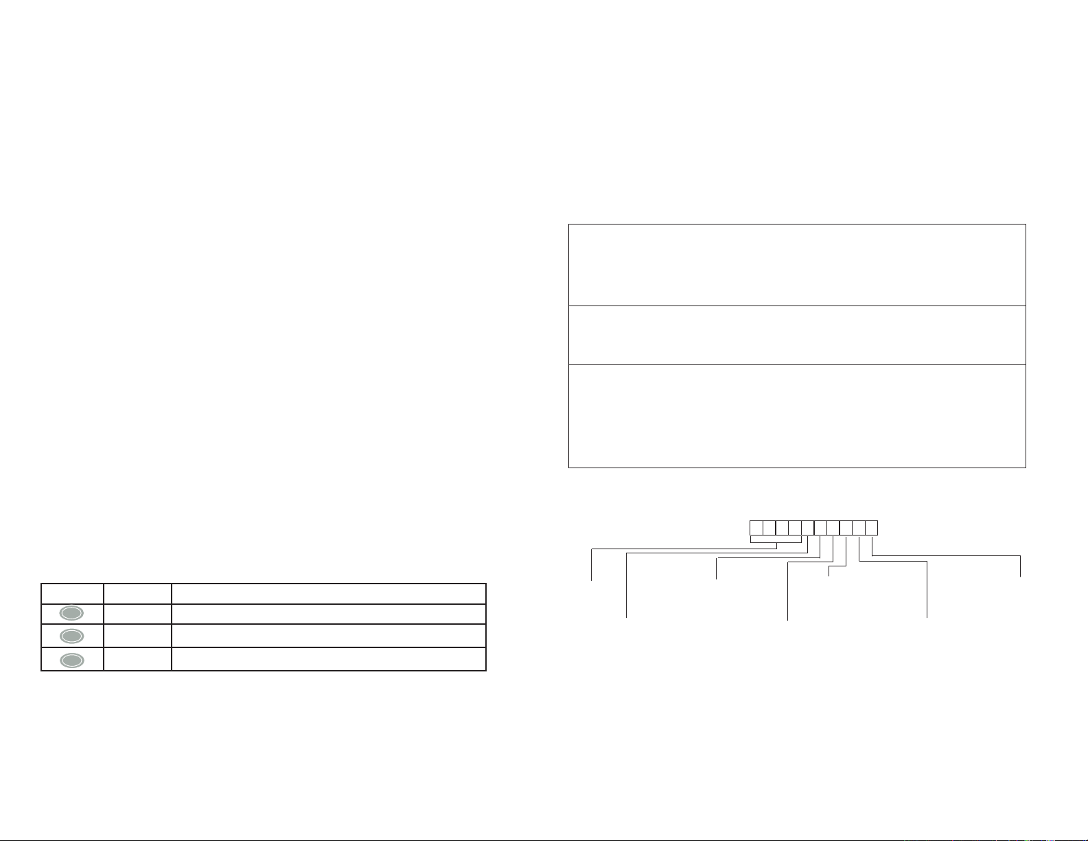
TABLE 2 CONFIGURABLE PART NUMBER
Example: Part No. 328G
TABLE 1 FACE BUTTON FUNCTION
Key Name Function
E
ENTER Accept Auto Zero and Auto Span Function
ZERO Auto Zero (section 4.1 above)
Z
UNITS Auto Span (see section: 4.1 above) and Units Change ( see section 4.3 page 3)
U
4.2 Decimal Points
The 328 decimal point is factory set and will self-adjust when changing measuring units.
2 3
Model
328G = 328
Input
M = 0-5 VDC
L = 0-10 VDC
B = 4-20 mA
Note: The character “Z” is used to identify customer specific options in all fields.
(Consult Factory)
1 = 25.0
2 = 50.0
3 = 100.0
4 = 250
5 = 500
6 = 1000
7 = 3.00Kpsi
8 = 10.0
9 = 20.0
Pressure Range
Bar Range
PSI Range
A
B = 3.40
C = 7.00
D = 17.0
E = 34.0
F = 70.0
G = 210
H = 200
J = 35.0
L = 1000
= 1.70
Pressure
G = Gage
C = Compound
A = Absolute
Torr
Transducer Conn.
D = 15 pin Female D-sub, Rear
E = 9 Pin Female D-Sub, Rear
D = 15 Pin Male D-Sub, Bottom
E = 9 Pin Male D-Sub, Bottom
System Conn.
Options
NS = Switchable
Page 3

6.0 RETURNING PRODUCTS FOR REPAIR
Please contact a Setra application engineer (800-257-3872, 978-263-1400) before returning
unit for repair to review information relative to your application. Many times only minor field
adjustments may be necessary. When returning a product to Setra, the material should be
carefully packaged and accompanied by Setra’s Calibration and Service Order Form found at
www.setra.com/tra/repairs/pdf/webrepair.pdf., and shipped prepaid to:
Setra Systems, Inc.
159 Swanson Road
Boxborough, MA 01719-1304
Attn: Repair Department
Notes: Please remove any pressure fittings and plumbing that you have installed and en
-
close any required mating electrical connectors and wiring diagrams.
Allow approximately 3 weeks after receipt at Setra for the repair and return of the unit.
Non-warranty repairs will not be made without customer approval and a purchase order to
cover repair charges.
Calibration Services
Setra maintains a complete calibration facility that is traceable to the National Institute of
Standards & Technology (NIST). If you would like to recalibrate or recertify your Setra pressure transducers, please call our Repair Department at 800-257-3872 (978-263-1400) for
scheduling.
7.0 WARRANTY AND LIMITATION OF LIABILITY
SETRA warrants its products to be free from defects in materials and workmanship, subject to the following terms and conditions: Without
charge, SETRA will repair or replace products found to be defective in materials or workmanship within the warranty period; provided that:
a) the product has not been subjected to abuse, neglect, accident, incorrect wiring not our own, improper installation or servicing, or
use in violation of instructions furnished by SETRA;
b) the product has not been repaired or altered by anyone except SETRA or its authorized service agencies;
c) the serial number or date code has not been removed, defaced, or otherwise changed; and
d) examination discloses, in the judgment of SETRA, the defect in materials or workmanship developed under normal installation, use
and service;
e) SETRA is notified in advance of and the product is returned to SETRA transportation prepaid.
Unless otherwise specified in a manual or warranty card, or agreed to in writing and signed by a SETRA officer, SETRA pressure and acceleration products shall be warranted for one year from date of sale.
The foregoing warranty is in lieu of all warranties, express, implied or statutory, including but not limited to, any implied warranty of
merchantability for a particular purpose.
SETRA’s liability for breach of warranty is limited to repair or replacement, or if the goods cannot be repaired or replaced, to a refund of the
purchase price. SETRA’s liability for all other breaches is limited to a refund of the purchase price. In no instance shall SETRA be liable for
incidental or consequential damages arising from a breach of warranty, or from the use or installation of its products.
No representative or person is authorized to give any warranty other than as set out above or to assume for SETRA any other liability in connection with the sale of its products.
SS328 Rev.A 4/27/2010
For all CE technical questions, contact Setra Systems, USA. EU customers may contact our EU representative Hengstler GmbH, Uhlandstr 49, 78554
Aldingen, Germany (Tel: +49-7424-890; Fax: +49-7424-89500).
159 Swanson Road, Boxborough, MA 01719, Tel: 800-257-3762,
Fax: 978-264-0292, Email: sales@setra.com, Web: www.setra.com
4
 Loading...