

Page 1
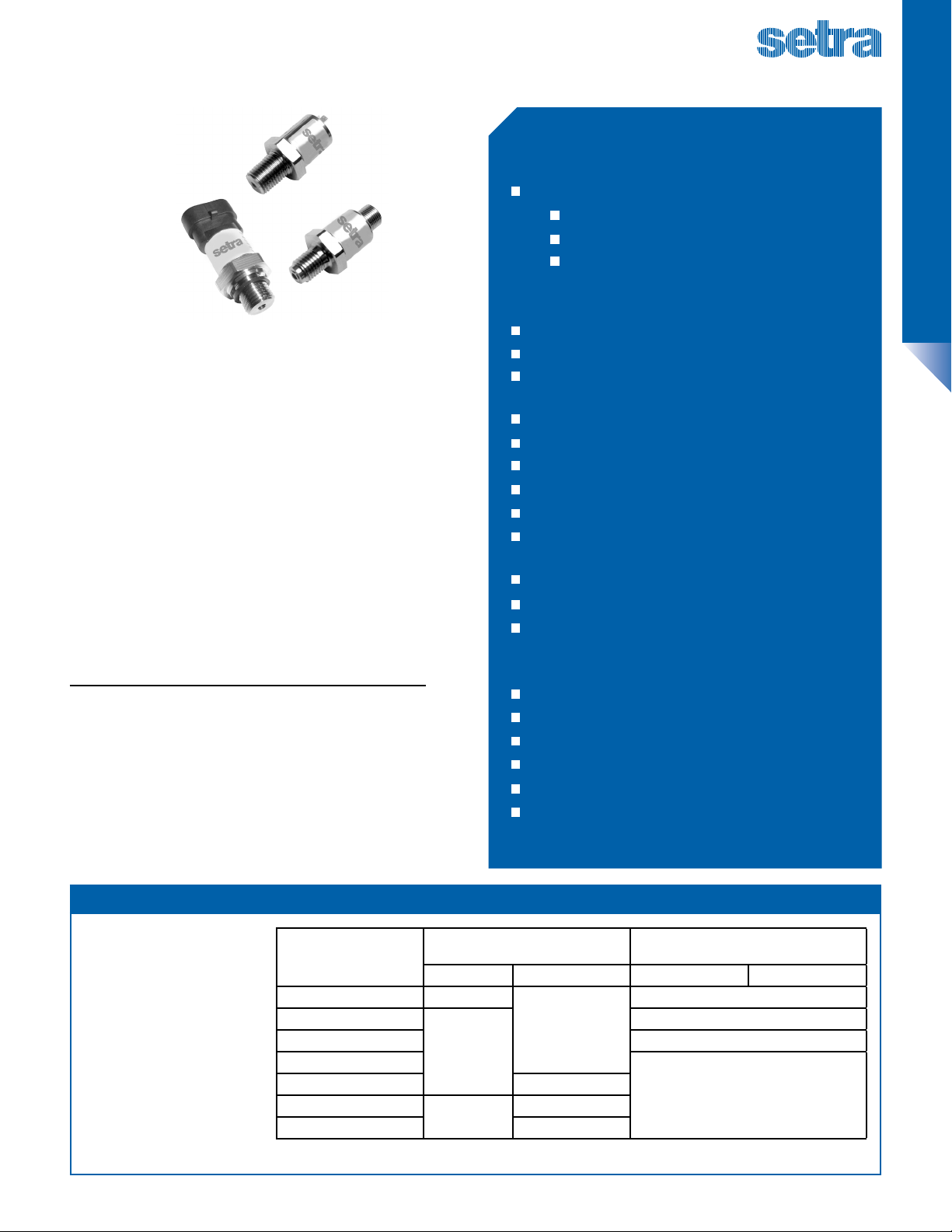
Model 31CS/32CS
Standard & Heavy Duty Intrinsically Safe CSA Rated Pressure Transducers
FEATURES
CSA Certied Intrinsically Safe for use in:
Class I, Division 1, Groups C & D
Class I, Zone 0 Ex ia IIB T4 Ga
Class I, Zone 0 AEx ia IIB T4 Ga
When Used in Conjunction with a Zener Safety Barrier
GENERAL PURPOSE/OEM
DESCRIPTION
For applications in hazardous areas that need intrinsically
safe pressure sensors with consistent high levels of
performance, reliability and stability. The 31CS/32CS Series
sputtered thin lm units oer an unbeatable price-toperformance ratio in a small package size. They feature all
stainless steel wetted parts, a broad selection of electrical
and pressure connections, and a wide choice of electrical
outputs ready for installation.
For heavy duty applications, the 32CS Series feature a thicker
diaphragm and a pressure resistor to withstand the rigors
of cavitation or extreme pressure spikes, delivering years or
reliable and stable performance in pulsating applications.
For ATEX & IECEx intrinsically safe pressure transducers,
refer to Setra’s 31IS/32IS.
PRINCIPLE OF OPERATION
Sputtered Thin Film Strain Gauge Pressure Sensors
Using the well proven Wheatstone Bridge principle,
molecular layers are sputtered onto a 17-4 PH stainless steel
diaphragm and the circuit is etched to provide excellent
resistor denition and uniformity. Sputtered thin lm
technology allows the design of simple, highly accurate
and compact strain gauges deposited onto the back of
the sensing diaphragm, which is in direct contact with the
media. This method virtually eliminates drift, while oering
enhanced sensitivity.
Low Cost for High Volume OEM Installations
Thin Film Tech. Assures Long-Term Stability
No Oil Fill Prevents Thermal Instability &
Leakage
Pressure Ranges from 75 PSI up to 32,000 PSI
Long-Term Stability Better Than ±0.1% FS/Yr
0.25% Full Scale Accuracy
Small Footprint -Less than 1 inch Diameter
Reverse Wiring Protected
Accuracy Specied Over Full Temperature
Range
All Welded Stainless Steel Construction
No Internal Elastomers, no RTV’s or Epoxies
CE, RoHS Compliant
APPLICATIONS
Industrial Processes
Chemical
HVAC/R Equipment
Water Management
Intrinsically Safe Control Panels
Other Hazardous Areas
PRESSURE CAPABILITY
Application pressure should be
restricted to the rated-range of
the transducer. The maximum
overpressure is the pressure limit
at which the transducer will not
show signicant oset shift. The
minimum burst pressure is the
test-rating for uid containment.
The data in the tables is “times
rate ranges” (xRR).
©2013 Setra Systems, Inc. All rights reserved. The Setra Systems name and logo are registered trademarks of Setra Systems, Inc. Phone: 800-257-3872 • Fax: 978-264-0292 • www.setra.com
Pressure Range
PSI (BAR)
100-300 (7-20) 3.00 x FS
500-1,500 (40-100)
2,000-6,000 (140-400) 10 x FS
10,000 (700)
15,000 (1,000) 2.50 x FS
25,000 (1,800)
30,000 (2,200) —
Proof Pressure
(x Full Scale)
31CS 32CS 31CS 32CS
3.00 x FS
2.00 x FS
1.40 x FS
1.70 x FS
Burst Pressure
(x Full Scale)
40 x FS
20 x FS
>60,000 PSI
(4,000 Bar)
Page 2
Model 31CS/32CS
Standard & Heavy Duty Intrinsically Safe CSA Rated Pressure Transducers
SPECIFICATIONS
Performance Electrical Data
Accuracy1 RSS ±0.25% FS Voltage
Long Term Drift 0.2% FS/YR (non-cumulative) Output (3-Wire) OV min to 10V max.
Thermal Error
31CS ±1.5% max, ±1% typical/212ºF (100ºC)
32CS ±2% max Source & Sinks 2 mA
GENERAL PURPOSE/OEM
Compensated Range -4 to +176ºF (-20 to +80ºC) Current
Operating Temp -40 to +176ºF (-40 to +80ºC) Output (2-Wire) 4-20 mA
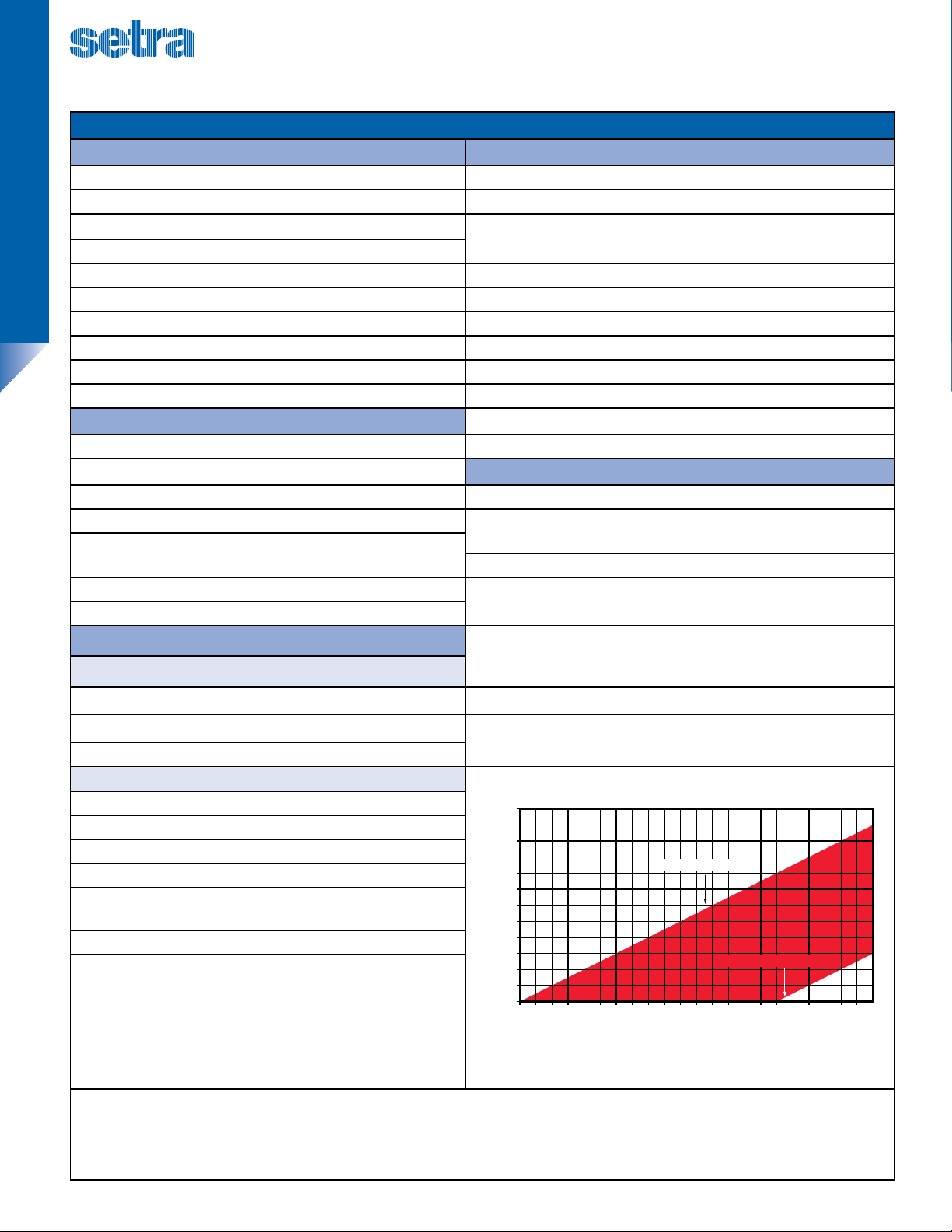
Zero Tolerance Max. 0.5% of Span Supply Voltage 8-24 Volts measured at the input to the transducer terminals
Span Tolerance Max. 0.5% of Span Max Loop Resistance (Supply Voltage - 8) x 50 ohms. See Graph Below
Fatigue Life Designed for more than 100M cycles Ratiometric Output
Physcial Description
Output 0.5 to 4.5V (Source & Sink 2 mA)
Pressure Port See Ordering Information Supply Voltage 5 VDC ±10% at 4.5 mA
Wetted Parts
2
17-4 PH Stainless Steel (Diaphgram)
EMC Specications
Electrical Connection See Ordering Information Emission Tests: EN61326-1:2006 and EN61326-2-3:2006
Enclosure IP67 (IP65 for Electrical Code A) EN55011:2007 Radiated Emissions 30-230MHz 30dB µV/M @10M
Vibration BSEN 60068-2-6 (FC) Sine (20G)
BSEN 60068-2-64 (FH) Random (14.1 Grms)
Immunity Tests: EN61326-1:2006 and EN61326-2-3:2006
Shock BSEN 60068-2-27 (Ea) (50G, 11ms) EN61000-4-2:2009 Electrostatic
Weight (Conguration dependant.) 1.8 to 5.3 oz (50-150 grams).
Zener Barrier & Entity Parameters
EN61000-4-3:2006 Radiated
Zener Barrier Parameters
Voltage Ui = 30VDC EN61000-4-4:2004 Fast Transients:
Current Li = 100mA
EN61000-4-6:2007 Conducted
Power Pi = 0.7W
Entity Parameters RL Load Limitations for Current Output Mode:
Signal Current In = 4 to 20mA
Eective Internal Capacitance Ci = 323n
Eective Internal Inductance Li = 9µh
Values to be added when supplied with integrated cable:
Cable Capacitance Ci = 300pF / m (max) Wire-to-Wire
or Wire-to-Shield
Cable Capacitance Li = 2µH / m (max) Wire-to-Wire
1
RSS of Non-Linearity, Hysteresis, and Non-Repeatability.
2
Note: Hydrogen not recommended for use with 17-4 PH Stainless Steel.
3
Reverse Wiring Protected
3
Supply Voltage 1 Volt above full scale with min supply of 8V;
max 30V at 4.5mA
3
230-1000MHz 37dB µV/M @10M
±4Kv contact
Discharge:
±8Kv air
10V/M 80-1000MHz
Immunity:
3V/M 1400-2000MHz
1V/M 2000-2700MHz
±0.25, 0.5, 1Kv
3V 0.15 to 80MHz 80% 1KHz
Immunity:
1200
1100
1000
900
800
700
600
500
400
300
200
CUSTOMER LOAD RESISTOR (OHMS)
100
0
8
9 10 11 12 13 14 15 16 17 18
Min Resistor (RL) = 50 * (Vdd-24): for Vdd>24V
Max Resistor (RL) = 50 * (Vdd-8): for Vdd>8V
MAXIMUM RESISTOR (RL)
CUSTOMER SUPPLY VOLTAGE (V)
modulation
MINIMUM RESISTOR (RL)
19 20 21 22 23 24 25 26 27 28 29 30
Specications subject to change without notice.
Phone: 800-257-3872 • Fax: 978-264-0292 • www.setra.com ©2013 Setra Systems, Inc. All rights reserved. The Setra Systems name and logo are registered trademarks of Setra Systems, Inc.
Page 3

Model 31CS/32CS
Standard & Heavy Duty Intrinsically Safe CSA Rated Pressure Transducers
ELECTRICAL FITTINGS
M12 Deutsch DT01-4P
2
KEY
3
1
4
2
1
Industry Standard
3
4
POLARIZING
WIDE CONTACT
Form C
2 3
4 1
Code E Code 8 Code R Code G Code 6 Code 9
Voltage Current Voltage Current Voltage Current Voltage Current Pin # Voltage Current Pin # Voltage Current
Pin #
1 +IN +IN 0V 0V +IN +IN +IN +IN 1 +OP DNC A 0V 0V
2 +OP DNC +IN +IN 0V 0V 0V 0V 2 0V 0V B +IN +IN
3 0V 0V NC NC +OP DNC +OP DNC 3 +IN +IN C +OP DNC
4 NC NC +OP DNC NC NC NC NC
Recommended Mating Connector:
To IEC 61076-2-101 Hirschmann, Brad Harrison,
Lumberg
Integrated Cable
Color Voltage Current
Red +IN +IN
Black 0V 0V
White +OP
Recommended Mating Connector:
DT064S-P012 as connector plug,
W4S-P012 as wedge, 0462-2011631 as gold socket (x4)
NOTES:
DNC: Do Not Connect (Leave Floating). NC: Not Connected at Transducer End
Alternative pin-outs are not available.
Recommended Mating Connector:
Hirschmann GDS 307 Part Number
933 024-100 or equivalent
The integrated cable is shielded. For compliance with EN 61000-4-5, shielded cable should be used on all transducers.
Substitution of Components May Impair Suitability For Intrinsic Safety
EN175301-803
(DIN 43650 A)
3
2 1
E
Recommended Mating Connector:
Molex/Brad/mPm Series 121201
(C28300N0S) or equivalent
WARNING
AMP Superseal 1,5 Series METRIPACK T (150 SERIES)
A
C
2 3 1
Recommended Mating Connector:
282087-1 as housing, 183025-1 as contact (x3),
281934-3 as wire seal (x3), 880811-2 as protective
boot (strain relief)
Recommended Mating Connector:
12065286 as connector body. 12052893 as
connector seal. Consult Delphi Packard for
appropriate contacts and wire seals.
B
GENERAL PURPOSE/OEM
PRESSURE FITTINGS
SAE
Dimensions
in Inches
Fitting Code 08 4D 02 0E 4C
Torque 2-3 TFFT* 2-3 TFFT* 2-3 TFFT* 2-3 TFFT* 2-3 TFFT*
Dimensions
in Inches
Fitting Code 4N 1J 04 1G 1P
Torque 18-20 NM 18-20 NM 15-16 NM 18-20 NM 18-20 NM
BSP & Metric
Dimensions
in Inches
1/8”- 27 NPT* 1/8”- 27 NPTF Dryseal 1/4” - 18 NPT 1/4” - 18 NPT Internal 1/4” - 18 NPTF Dryseal
0.28
0.57
SAE J1926/2:3/8-24 w/o
O-Ring*
0.28
0.44
G1/4” - 19 External w/
O-Ring*
0.28
0.57
0.47
0.37
0.47
0.28
0.37
7/16” - 20 UNF w/ O-Ring* 7/16”-20 UNF w/37º Flare
0.28
0.5
G1/4”-19 A Integral Face
Seal*
0.28
0.57
0.47
0.28
0.28
M12 x 1.5 w/ O-Ring*
0.28
0.57
0.55
0.37
0.47
0.28
SAE 4 Female 7/16”
Schraeder
0.28
M12 x 1.5 HP Metal
Washer Seal*
0.28
0.57
0.28
0.37
9/16”-18 “Heavy Duty” w/
0.28
0.43
0.57
M14 x 1.5 w/ O-Ring*
0.28
0.47
0.57
0.37
O-Ring
0.47
0.47
Fitting Code 01 05 0L 2T 0K
Torque 30-35 NM 30-35 NM 28-30 NM 30-35 NM 2-3 TFFT*
*O-Rings are not supplied with pressure ttings.
NOTE: Not all available pressure connectors are shown. Please consult the factory for additional congurations.
©2013 Setra Systems, Inc. All rights reserved. The Setra Systems name and logo are registered trademarks of Setra Systems, Inc. Phone: 800-257-3872 • Fax: 978-264-0292 • www.setra.com
Page 4

Model 31CS/32CS
Standard & Heavy Duty Intrinsically Safe CSA Rated Pressure Transducers
ORDERING INFORMATION
Model Pressure Range Pressure Port Connector Output Cable Length
31CS Standard Duty See Table 1 See Table 2 See Table 3 See Table 4 See Table 5
32CS Heavy Duty
GENERAL PURPOSE/OEM
Table 1. Pressure Range
CODE BAR CODE PSI
GAUGE
0004G 4 075PG 75
0006G 6 100PG 100
0010G 10 150PG 150
0016G 16 200PG 200
0025G 25 300PG 300
0040G 40 500PG 500
0060G 60 10CPG 1,000
SEALED
0100S 100 15CPS 1,500
0160S 160 20CPS 2,000
0250S 250 35CPS 3,500
0400S 400 50CPS 5,000
0600S 600 10KPS 10,000
1000S 1,000 15KPS 15,000
1600S 1,600 20KPS 20,000
2200S 2,200 25KPS 25,000
Table 2. Pressure Port
CODE DESCRIPTION CODE DESCRIPTION
0H 1/2” NPT 1J 7/16” - 20 UNF 2A SA1926/2 O’RING
02 1/4” - 18 NPT 1P 9/16” - 18UNF 22 A/F
0E 1/4” - 18 NPT Female 4P G1/2” A 27A/F
4C 1/4” - 18 NPT Dryseal 05 G1/4” A Integral Face Seal
0A 1/4” - 19 PT (JIS) or 1/4” - 19 BSPT 01 G1/4” A Stud (BS 5380 Port
4B 1/4” Female (7/16UN with Shraeder Deator) 0S G1/8” A Stud (BS 5380 Port)
08 1/8” 27 NPT 2T M12x1.5 (6g) High Pressure (Washer Seal)
4D 1/8” 27 NPTF Dryseal 0L M12x1.5P (6g) O’R ing to ISO 6149-2
4N 3/8” - 24 UNF Union 1G Schraeder 7-16” - 20 UN 2B Female
04 7/16” 20 (37FLARE SAE J514 SIZE 4)
30KPS 30,000
32KPS 32,000
Table 3. Connector
CODE DESCRIPTION
6 Amp Superseal 1.5 Series
8 Deutsch DT04-4P
9 Metripack T (150 Series)
E M12
G EN175301-803 (DIN 43650 A)
R Industry Standard Form C
F Integrated Cable
Table 4. Output
CODE Output TYPE
B 4-20 mA Current
C 1-6 V Absolute
F 0.1-5.1 V Absolute
G 0.2-10.2V Absolute
H 1-5 V Absolute
N 0.5-4.5 V Non Ratio-metric Absolute
P 1-10 V Absolute
R 0-5 V Absolute
S 0-10 V Absolute
T 0.5-4.5 V Ratio-metric R atio-metric
V 0.5-4 V Absolute
Table 5. Cable Length
CODE DESCRIPTION
00 Not Fitted
01 1 meter
02 2 meter
03 3 meter
05 5 meter
10 10 meter
NOTE:
Cable lengths longer than 10 meters are not available
Phone: 800-257-3872 • Fax: 978-264-0292 • www.setra.com ©2013 Setra Systems, Inc. All rights reserved. The Setra Systems name and logo are registered trademarks of Setra Systems, Inc.
3xCS Data Sheet (CSA) 06/2013
 Loading...